 Open Access Article
Bimetallic nickel/manganese phosphate–carbon nanofiber electrocatalyst for the oxidation of formaldehyde in alkaline medium†
Ibrahim Elghamry*,
Samya A. Al-Jendan*,
M. M. Saleh and
Mamdouh E. Abdelsalam
Department of Chemistry, College of Science, King Faisal University, P. O. Box 400, Al-Ahsa, 31982, Saudi Arabia. E-mail: ielghamry@kfu.edu.sa; Sa07.aziz@gmail.com
First published on 18th July 2022
Abstract
The development of earth-abundant transition metal-based catalysts, supported by a conductive carbonaceous matrix, has received great attention in the field of conversion of formaldehyde derivatives into toxic-free species. Herein, we report a comprehensive investigation of bimetallic electrocatalyst activity towards the electrooxidation of formaldehyde. The bimetallic phosphate catalyst is prepared by co-precipitation of Ni and Mn phosphate precursors using a simple reflux approach. Then the bimetallic catalyst is produced by mixing the Ni/Mn with carbon fibres (CNFs). The structural properties and crystallinity of the catalyst were investigated by using several techniques, such as scanning electron microscopy, X-ray diffraction, energy-dispersive X-ray spectroscopy, and Brunauer Emmett−Teller theory. The system performance was studied under potentiostatic conditions. Some theoretical thermodynamic and kinetic models were applied to assess the system performance. Accordingly, key electrochemical parameters, including surface coverage (Γ) of active species, charge transfer rate (ks), diffusion coefficient of the formaldehyde (D), and catalytic rate constant (kcat) were calculated at Γ = 1.690 × 10⁻⁴ mmol cm−2, ks = 1.0800 s−1, D = 1.185 × 10⁻³ cm2 s−1 and kcat = 1.08 × 105 cm3 mol−1 s−1. These findings demonstrate the intrinsic electrocatalytic activity of formaldehyde electrooxidation on nickel/manganese phosphate- CNFs in alkaline medium.
1. Introduction
Over recent years, the reserve storage of carbon fossil fuels has rapidly depleted. Additionally, the detrimental impacts of using fossil fuels have caused an aquatic environment pollution crisis. Consequently, the demand for developing eco-friendly fuel for clean energy conversion devices, such as fuel cells, has recently attracted significant attention.1 Direct fuel cells based upon electrooxidation of simple organic molecules such as alcohol,2,3 urea,4,5 formic acid,6–8 and formaldehyde9–11 have been reported as clean energy generation technologies.12 Various studies have been geared towards understanding the potential of developing fuel cells using the formaldehyde electrooxidation process as an attractive replacement for conventional fuel. The electrooxidation of formaldehyde possesses many advantages. For instance, formaldehyde is used as a keystone for the insight of partial methanol oxidation in direct methanol fuel cells (DMFC).13–15 Also, formaldehyde is utilized in diverse industrial applications such as textile manufacture, and electroless copper plating.16 Furthermore, formate ions HCOO− that are produced during formaldehyde electrooxidation have the potential to become a prominent candidate for replacing fossil fuels in direct formate fuel cells to generate clean energy. Additionally, direct formate fuel cells (DFFC) have higher cell voltage values than direct alcohol fuel cells (DAFCs), which leads to the production of more energy.17,18 Furthermore, formaldehyde is directly produced as an intermediate during the electrocatalytic conversion of CO2.19,20Electrocatalytic oxidation of formaldehyde on the surface of metallic modified electrodes has attracted significant interest.21,22 Generally speaking, noble metal-based materials are well-known to deliver an outstanding performance as catalysts for the electrooxidation of small organic molecules. For example, SnO2/Pt,16 Pd nanoparticles (NPs)/multi walls carbon nanotubes (WCNTs),22 Pt–Pd/graphene (GR),21 and Pt– Pd NPs/polypyrrole-CNT,23 showed benchmark performance towards the anodic electrocatalytic oxidation of formaldehyde. However, the main drawbacks of these precious metals are their high cost and the rapid deactivation of their surfaces by adsorption of formed intermediates from the oxidation of formaldehyde.24 Consequently, massive endeavours have been allocated to find efficient and cost-effective alternatives.
Phosphate materials possess large channels within the open crystalline structure framework, making them perfect candidates as electrocatalysts.25 Consequently, the outstanding properties of nickel phosphate materials enable them to be commonly used for a variety of applications, including supercapacitors,26 LIB,27 and non-enzymatic sensors.28 Moreover, nickel phosphate (NiPh) electrocatalyst has been capable of catalysing and improving the performance of urea oxidation,29 methanol,30 glucose,31 formaldehyde in alkaline medium,32 and glycerol in the neutral medium.33 The activity of the NiPh electrocatalyst is attributed to the flexible and stable structural properties, chemical and thermal stability, and its multiple oxidation states. Also, NiPh is an inexpensive material and may be reduced to another form of an efficient electrocatalyst like nickel phosphide (Ni3P–Ni2P) which was used in many catalytic applications.34
Hureaulite has been categorized as a part of widespread species of hydrated manganese phosphate family (XH-MnPh) with Mn5(PO3(OH))2(PO4)2·4H2O structure. It has been commonly utilized as an additive to achieve high surface corrosion-resistance to strengthen the wear-resistant of steels.35 In recent years, hureaulite synthetic methodologies and physicochemical properties have attracted massive attention in material and mineralogical sciences. Nevertheless, using hureaulite in electrocatalytic oxidation of formaldehyde is scarce.
Monometallic-based materials have been widely used as eminent alternatives for many electrocatalytic applications. However, their low catalytic activity, which may be ascribed to using a single component of transition metal-based catalysts, and their low ability of charge transfer was greatly obstructed their applications. In order to tackle this issue, the strategy of designing a bimetallic catalyst was proposed. Generally, more redox reactions are successfully initiated from the combination of multiple valence states of bimetallic ions. Thus, the voltage window of the redox reaction will be enlarged due to increasing the active sites on the surface of the bimetallic catalysts. Meanwhile, the activity and stability of electrocatalysts were enhanced by using bimetallic materials.36 Based on the above-mentioned properties, bimetallic nickel-based materials have been employed in different energy conversion applications especially, supercapacitors,37 and as anode materials in LIBs.38 In addition, they have been used in electrocatalytic reactions for glucose,39 urea,40 and methanol41 oxidation in alkaline medium. Multi-metallic materials such as, ternary Ni–CuCo/graphene (GR), binary NiO/MnO,42,43 binary Pd/Sn,44 Pd-WC/GR,45 have outstanding performance for methanol, formic acid, and ethanol oxidation, respectively. Fe/FeZM-CPE,46 Ni–Pd/SiMCP,47 Pd/PPy composite,48 and CuO/Cu/TiO2 nanotube arrays,49 offered superior electroactivity for the formaldehyde oxidation than mono metallic catalysts. Also, bimetallic Pd/Cu2O nanoclusters,50 and (NiWO4) nanoparticles,51 showed better electroactivity for formaldehyde oxidation than individual metallic materials. These results were attributed to the synergistic effect between transition metals in the electrocatalysts. Although bimetallic electrocatalysts have emerged as an auspicious catalyst in many applications, the lack of their electrical conductivity has motivated urgent demand to find further alternatives with high electrical conductivity.
A short while ago, incorporated bimetallic-based materials into carbon support materials have been considerably employed in many electrocatalysis applications. Carbon conductive matrices such as carbon nanotubes,52,53 graphene,54 and carbon nanofibers (CNFs)55 have been used because of their intrinsic properties such as high electrical conductivity, large surface area, and good chemical and electrochemical stability properties. Benefiting from the unique characteristics of graphitic materials, nanocomposite NiCo2O4/MWCNTs aerogel,56 Ni–Cr/C,57 N-doped reduced graphene oxide RGO supported by nano-Ni–CoO4,58 bimetallic Ni–Sn/CNFs nanocomposite,55 Bimetallic NiMn alloy/CNFs,40 have been applied as a modified electrodes for different electrocatalytic oxidation applications and offered higher catalytic activity and stability than pristine electrode materials.
Notably, in this work, we first sought to use tetra-hydrated manganese phosphate (hureaulite) as a novel co-catalyst to improve the catalytic activity of nickel phosphate octa hydrates toward formaldehyde electrooxidation. Nickel (Ni)/manganese phosphates (MnPh) electrocatalyst is typically synthesized by simple reflux methodology. Bimetallic phosphates material is mixed with CNFs to form bimetallic Ni/MnPh-CNFs catalyst. Physicochemical and electrochemical properties of as-synthesized materials are characterized by using various techniques. Electrochemical techniques were also used to evaluate the electrocatalytic performance of the proposed catalyst.
2. Experimental
2.1. Chemicals and materials
All solvents and reagents throughout the current study were commercially pure products and used as received without any further purification. Manganese acetate, Mn (CH3COO)2, nickel nitrate hexahydrate, Ni (NO3)2·6H2O, and ammonium dibasic phosphate, (NH4)2HPO4, were purchased from Sigma Aldrich-United Kingdom. Deionized water was used to prepare all the solutions and rinse the electrodes during the experiment. The carbon nanofibers (CNFs), OD: 200–600 nm was ordered from the US Research Nanomaterials, Inc., Houston, USA. CNFs material was manufactured by CVD technique and has high purity >95 wt%. It possesses a tap density of 0.043 g cm−3 and a high electrical conductivity of 100 S cm−1. Also, potassium hydroxide, urea, Nafion, and formaldehyde 37–38% w/w STB MT, Nafion (5% water) were obtained from Pan Rec Applichem.2.2. Synthesis of nickel phosphate
NiPh material was synthesized by simple co-precipitation under mild conditions using a reflux system. The full description of the preparative approach can be found in the following ref. 59. Typically, a greenish precipitate of NiPh was prepared by mixing 5 ml nickel nitrate hexahydrates (1 M) with 5 ml of ammonium dibasic phosphate (1 M). After that, a small volume of 1 ml concentrated nitric acid, HNO3, was added for dissolving the greenish precipitate to form a homogenous solution. Subsequent addition of urea solution to the homogenous mixture was carried out. The green precipitate was produced by refluxing the mixture with constant stirring at 90 °C for 12 h. The resulting suspension was left to cool down to room temperature. Thereafter, the precipitate was extracted by filtration and washed several times by using deionized water. Finally, the precipitate was left in an oven to dry at 100 °C for 12 h.2.3. Synthesis of manganese phosphate
MnPh was also prepared using a simple reflux procedure. The preparation steps were thoroughly represented in the preceding synthetic methodology of NiPh. However, MnPh was obtained from mixing of (15 ml, 1 M) Manganese acetate and (5 ml, 1 M) of ammonium dibasic phosphate. Then, steps for NiPh preparation were followed, and the refluxing procedure was performed. Consequently, the light brown precipitate of MnPh was produced and ready for different characterizations.2.4. Synthetic methodology of bimetallic Ni/MnPh catalyst
NiPh and MnPh were synthesized from their precursors by a simple reflux procedure.32 Firstly, 14.540 g of nickel nitrate hexahydrate, Ni (NO3)2·6H2O, 8.65 g of manganese acetate, Mn (CH3COO)2, and 6.603 g of ammonium dibasic phosphate, NH4H2PO4 were transferred into separate 50 ml volumetric flask. Secondly, 50 ml of deionized water was added to each of them up to the calibration mark. Thirdly, (8 ml, 1 M) of nickel nitrate hexahydrates, and (2 ml, 1 M) manganese acetate, respectively. This mixture was mixed with (6.6 ml, 1 M) ammonium dibasic phosphate solutions. Then, the light green precipitate was directly formed. To the above precipitate, 1 ml of concentrated nitric acid has gradually added using a dropwise addition manner until the greenish precipitate was dissolved. Consequently, a homogenous uniform solution was produced. After that, (60 ml, 1.6 M) of the urea solution has added to the homogeneous mixture. Thereafter, the mixture was magnetically stirred using a simple reflux system at 90 °C. The refluxing process was prolonged for 12 hours. Then, the light green precipitate of Ni/MnPh was formed and naturally cooled down to room temperature overnight. Afterwards, the produced material was filtered and rinsed multiple times with deionized water. Then, the precipitate was left in an oven at 100 °C to dry for 12 hours. Finally, this material was ready for different physicochemical and electrochemical characterizations.2.5. Fabrication of NiPh/CNFs, MnPh/CNFs, and Ni/MnPh-CNFs electrodes
The phosphates electrodes were fabricated as the following protocol. Firstly, the bare glassy carbon electrode (GCE) ϕ = 3 mm diameter was mechanically polished with aqueous slurries of finer alumina powder (down to 0.06 μm). Then, GCE was rinsed initially by deionized water and followed by ethanol. Besides, for the electrochemical cleaning purpose of GCE, the potential cycling was implemented for 50 cycles in the potential window from −0.5 to +0.5 V, at 100 mV s−1 scan rate in 0.1 M of H2SO4 solution. 12 mg of NiPh or MnPh, or Ni/MnPh materials and a proper amount of CNFs (3 mg) were added into 2.5 ml of isopropanol and 50 μL of Nafion oil in a test tube with 30 min ultrasonic treatment to have a homogeneous suspension solution. At last, 20 μL of freshly prepared ink catalyst of NiPh/CNFs, or MnPh/CNFs, or Ni/MnPh-CNFs was taken and casted onto the surface of the GCE and left in the air to dry for overnight. The weight loading of Ni/MnPh-CNFs was 2.5 mg cm−2, i.e., the base GCE is coated with 0.18 mg of the investigated catalyst.2.6. Physicochemical characterization
The morphological and compositional characteristics of the as-synthesized materials were probed by field-emission scanning electron microscopy (FE-SEM, Model JEOL JSM-5410). SEM was equipped to carry out the elemental fingerprinting analysis using energy-dispersive X-ray spectroscopy (EDS). X-ray diffraction spectra (XRD) of investigated materials were recorded with X-ray diffractometer (PANalytical, X'Pert PRO). XRD equipped with monochromatic CuKα radiation. The crystallographic structure of materials was identified using wavelength (λ = 1.54 Å). XRD radiation was generated at 40 kV and a current of 44 mA with a scan rate of 2° min−1 over a 2° range of 4–80°. The chemical properties analysis of material was performed by X-ray photoelectron spectrometer (ESCA-II; Omicron, Germany).The pore size distribution and specific surface area (SSA) were calculated using Brunauer Emmett–Teller (BET). The samples were investigated under low-temperature (77.0 K) adsorption isotherms and using high purity nitrogen (99.999%). It measured over a wide range of relative pressures from 0.02 to 0.95. Adsorption measurements were carried out using a Micro-metrics ASAP2010 volumetric adsorption apparatus. The samples were initially degassed at 100 °C and prolonged for 6 h in the degas pot of the adsorption analyzer before starting the measurements. Also, Barrett Joyner–Halenda (BJH) was used for pore size distribution determination purposes.2.7. Electrochemical measurements
Electrochemical measurements including cyclic voltammetry (CV) and chronoamperometry (CA), were performed using electronic hardware of Gamry potentiostat/galvanostat. Standard three electrodes electrochemical cell configuration, a platinum wire as a counter electrode (CE), Pt, glassy carbon electrode, GCE as a working electrode (WE), saturated silver–silver chloride as a common reference electrode (RE), Ag/AgCl/3 mol L−1 KCl with a Luggin probe positioned near the electrode surface were normally employed in electrochemical measurements. The applied potential to the working electrode throughout the experiment was controlled by the reference electrode. Examining the reproducibility of the findings was made by repeating the measurements at least three times.3. Result and discussion
3.1. Surface morphology of electrode materials
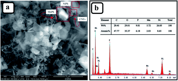
Fig. 1a presents the morphology and dimensions of the bimetallic Ni/MnPh-CNFs electrode. It indicates the NiPh sheets and hexagonal prismatic shape of MnPh particles that are connected by CNFs. The electrical wiring connections of CNFs between NiPh and MnPh particles improve the electrical conductivity and SSA of the material.The composition of Ni/MnPh-CNFs is confirmed by EDS (Fig. 1b). It consists of 26.05 wt% Ni, 5.72 wt% Mn, 29.01 wt% O, 9.81 wt% P, and 29.41 wt% of C. It is worth mentioning that the mass ratio of Ni![[thin space (1/6-em)]](https://www.rsc.org/images/entities/char_2009.gif) :
:![[thin space (1/6-em)]](https://www.rsc.org/images/entities/char_2009.gif) Mn is about 26.05
Mn is about 26.05![[thin space (1/6-em)]](https://www.rsc.org/images/entities/char_2009.gif) :
:![[thin space (1/6-em)]](https://www.rsc.org/images/entities/char_2009.gif) 5.72, which coincides with the volume ratio of 4
5.72, which coincides with the volume ratio of 4![[thin space (1/6-em)]](https://www.rsc.org/images/entities/char_2009.gif) :
:![[thin space (1/6-em)]](https://www.rsc.org/images/entities/char_2009.gif) 1. This was previously mentioned in the synthesis procedure of the Ni/MnPh-CNFs catalyst.
1. This was previously mentioned in the synthesis procedure of the Ni/MnPh-CNFs catalyst.
The surface morphology of CNFs is depicted in the FE-SEM micrograph (Fig. S1a†). The image shows a hollow fiber structure with a smooth surface. Additionally, the fiber has a high aspect ratio material with an outer nanoscopic diameter of 50–150 nm, and a length of 5 μm.60 Fig. S1b† shows the SEM image of NiPh/CNFs, which reveals the flake sheets of NiPh with an average size of 200–800 nm. The electrical wiring of the bimetallic electrode is improved by the addition of CNFs. Fig. S1c† shows the EDS pattern, which illustrates the elemental fingerprinting of NiPh/CNFs. It confirms the presence of nickel, oxygen, phosphorous, and carbon atoms. The surface morphology and dimensions of MnPh are also shown in Fig. S1d.† This image indicates three dimensions structure (170 nm × 300 nm × 800 nm) of MnPh particles. These particles have different sizes of hexagonal prismatic like-shape with a length up to 800 nm and diameters up to 300 nm. The EDS pattern of MnPh/CNFs is shown in Fig. S1e.† It reveals the presence of manganese, oxygen, carbon atoms, and a small quantity of phosphorous.
Fig. 2a(ii) shows the XRD pattern for CNFs, where exhibits the highly intensive characteristic peaks at 2θdiff = 26.21° and 42.8°.61 They were scrupulously recorded at diffraction angle range 0 < 2θdiff > 80. Also, Fig. 2a(i) displays the international center for diffraction data (ICDD) for graphite-2H with reference code 01-075-1621. Fig. 2b(ii) presents the peaks for the crystalline NiPh.62 CNFs peaks are marked by asterisks. The ICDD card for NiPh is included in Fig. 2b(i) with a reference code of 00-033- 0951. It demonstrates the structure of the arupite, Ni3(PO4)2·8H2O.63 According to Scherrer equation (eqn (1)), the average grain size of NiPh is estimated to be Dhkl ≃ 60 nm;64
 | (1) |
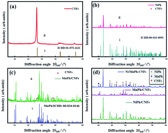 | ||
| Fig. 2 XRD pattern of (a) CNFs, (b)NiPh/CNFs, (c) MnPh/CNFs, and their ICDD cards are also included for comparison, (d) Ni/MnPh-CNFs. | ||
The crystallinity of MnPh sample is demonstrated in the XRD pattern (Fig. 2c(ii)). It can be noted that the diffraction peaks for as-synthesized MnPh are signified to the monocrystalline MnPh, indicating the crystallographic structure of hureaulite, Mn5(PO3(OH))2(PO4)2·4H2O. For comparison, ICDD card of MnPh is also included in Fig. 2c(i). The peaks for CNFs are marked by red asterisks (ICDD: 01-075-1621). Whilst the rest of the sharp peaks are for the MnPh particles. The average grain crystallite size for MnPh is determined at Dhkl = 71 nm. It was also calculated using Scherrer equation eqn (1).
Fig. 2d shows the XRD pattern of bimetallic Ni/MnPh-CNFs. The composition of the probed material is found to be hybridized Ni3(PO4)2·8H2O/Mn5(PO3(OH))2(PO4)2·4H2O-CNFs with a crystal structure. MnPh peaks are appeared at 2θdiff = 10.24 and 31.69 (ICDD: 00-034-0146). The diffraction peaks of CNFs are obtained at 2θdiff = 26.21° and 42.8. The rest of the intensive peaks are for NiPh (ICDD: 00-033-0951). The average crystallite grain size values of NiPh and MnPh particles are not significantly changed after the addition of CNFs.
The chemical properties of the surface were further investigated through X-ray photoemission spectroscopy. The spectra were calibrated to the C 1s peak. Fig. 3a shows the survey spectrum of the Ni/MnPh-CNFs confirming the existence of Ni, Mn and P elements. Considering the relative sensitivity factor, the surface atomic composition of the Ni/MnPh-CNFs, which was obtained from P 2p, Ni 3p and Mn 3p photoemission lines (Fig. 3b and c), is 53.13%, 36.16% and 10.71%, respectively. The Ni 2p core-line (Fig. 3d) consists of two major peaks at binding energy 856.2 eV and 873.7 eV, which are assigned to Ni 2p3/2 and Ni 2p1/2. The presence of Ni 2p3/2 peak at higher binding energy compared to Ni(HO)2 spectra, 855.7 eV, indicates an increase in the valence state of Ni at the surface.65 In contrast, determining the Mn oxidation state via Mn 3s is challenging due to the low presence of Mn on the surface.66 In Fig. 3b, the P 2p peak is centred at 133.3 eV, indicating that the phosphate group is bonded to the metal as P–Ni/Mn.67
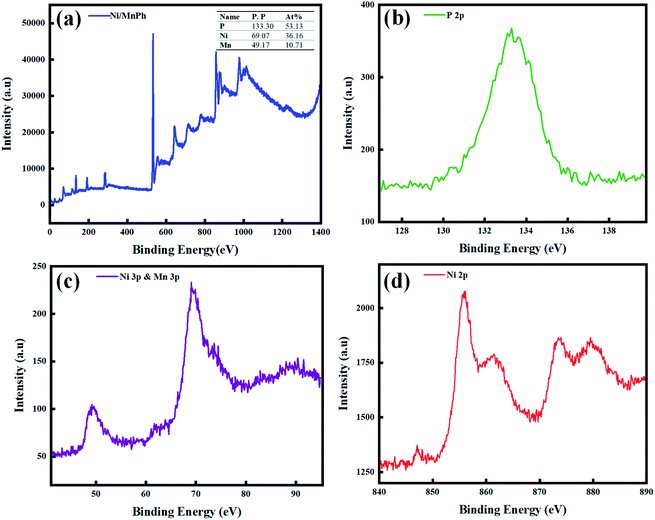 | ||
| Fig. 3 (a) The XPS survey spectrum of the Ni/MnPh-CNFs. (b) XPS of P 2p, (c) XPS of Ni 3P and Mn 3P (d) XPS of Ni 2p. | ||
Further analysis was performed to get more insight into samples structures throughout the investigation of pore size distribution and specific surface area (SSA) features using BET and BJH analysis. The obtained curves are depicted in Fig. S2† and 4.
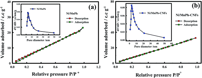 | ||
| Fig. 4 Nitrogen (N2) adsorption/desorption isotherm curve of (a)Ni/MnPh, (b)Ni/MnPh-CNFs catalysts. BJH curves of materials are indicated in the insets. | ||
The isotherms of all samples were categorized as type I or III according to the classification of the International Union of Pure and Applied Chemistry (IUPAC). These types of isotherms are assigned to slight convex at higher relative pressure values and without any hysteresis loops. They also indicate an unrestricted multilayer formation process of N2 gas during the analysis, which lead to a linear increase in adsorbed gas over the surface of the activated carbon-based material.68,69 The BET surface area (SSABET) values for the studied samples are reported in Table 1.
| Material | Used mass/g | SSABET/m2 g−1 | Pore diameter/nm | Pore volume/cm3 g−1 |
|---|---|---|---|---|
| CNFs | 0.0129 | 87.23 | 2–8 | 0.096 |
| NiPh/CNFs | 0.0412 | 32.00 | 2–9 | 0.062 |
| MnPh/CNFs | 0.0190 | 32.32 | 1–11 | 0.028 |
| Ni/MnPh | 0.0250 | 33.24 | 1–14 | 0.032 |
| Ni/MnPh-CNFs | 0.0190 | 47.23 | 2–12 | 0.046 |
The SSABET are roughly 87.23, 32.00, 32.32, 33.24, 47.23 m2 g−1, for CNFs, NiPh/CNFs, MnPh/CNFs, Ni/MnPh, Ni/MnPh-CNFs, respectively, indicating the high surface area of bimetallic phosphates-CNFs among phosphates catalysts. As seen in BJH-curve of CNFs (Fig. S2a† inset), a sharp peak appears at 5 nm while the broad peak markedly indicates the existence of larger pores distribution between 10–20 nm.69–71 The BJH curves (Fig. S2b and c† and 4 insets) demonstrate the porosity nature of different phosphates materials.
3.2. Electrochemical characterization of Ni/MnPh-CNFs electrocatalyst
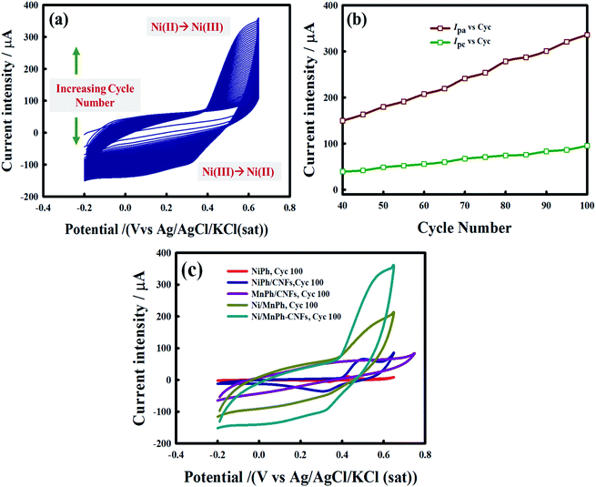
Electrochemical performance of Ni/MnPh-CNFs electrode in alkaline solution (0.25 M KOH) was tested using cyclic voltammetry technique. Ni/MnPh-CNFs electrode was activated before using in electrooxidation processes by CV with scanning the potential ranging from −0.2 to 0.65 V at 100 mV s−1 scan rate. The consecutive CVs were recorded for 100 cycles. 50 cycles were plotted for clarification, as shown in Fig. 5a. The increasing of accessible active sites Ni(II)/Ni(III) during the activation process is attributed to the presence of Mn(II) and CNFs components in the catalyst.The maximum anodic peak current is about 340 μA. It is recorded at approximately +0.6 V, whereas the broad cathodic peak potential on the reverse sweep is appeared at around −0.33 V. It is noticeable that there is no significant shift in the peak potential from cycle to cycle. However, the peak current gradually increases with increasing the cycle number Fig. 5b. The height of peak current regarding the cycle number 100th for Ni/MnPh-CNFs is higher than that for other phosphates electrodes (Fig. 5c). The absence of cathodic and anodic current peaks in cycle number 100th of MnPh/CNFs electrode is assigned to the inactive nature of MnPh species. It was only used to enhance the formation of Ni3+ throughout the OH− insertion and extraction processes.
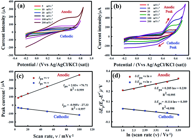
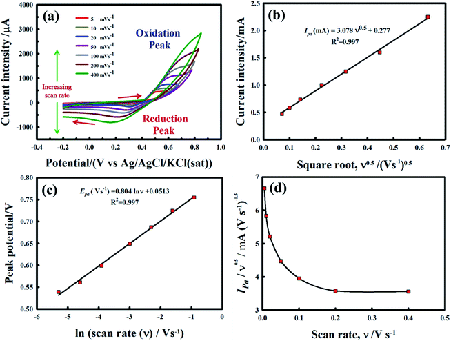
Fig. 6 exhibits the CVs for MnPh/20 wt% CNFs (Fig. 6a), and Ni/MnPh-20 wt% CNFs (Fig. 6b) electrodes in 0.25 M KOH solution at various potential scan rates. The current-potential response of mono NiPh/20 wt% CNFs catalyst is indicated in the previous work at different scan rates.72 The redox peaks for the insertion/extraction of OH-are not clear for the MnPh/CNFs electrode. However, the charging current is increased with increasing the scan rate. On the other hand, the anodic Ipa and cathodic Ipc peaks current are dramatically augmented with increasing scan rate for the Ni/MnPh-CNFs due to the synergistic effect between NiPh and MnPh and the presence of high electrical conductive CNFs. CV response for bimetallic phosphates is higher than mono NiPh/CNFs. The anodic peak potential is shifted to a more positive value, whereas the cathodic peak potential is slightly moved to a less positive direction. Also, the peak separation ΔEp increases with increasing scan rate from 5 to 200 mV s−1.15 The peak potential separation at scan rates ν = 10, 20, 50, 100, and 200 mV s−1 are estimated to be ΔEp = 206, 242, 273, 304, and 369 mV s−1 respectively, which points to the quasi-reversible characteristic of the process (i.e., ΔEp > 59/n mV s−1). Fig. 6c shows the linear increase of current intensity values (Ipa and Ipc) with scan rates of 5 mV s−1 → 200 mV s−1. The resulting straight line indicates that the process is a surface-confined redox system.72 Also, the linear increase of δEp with ln![[thin space (1/6-em)]](https://www.rsc.org/images/entities/char_2009.gif) ν is indicated in Fig. 6d.
ν is indicated in Fig. 6d.
Laviron's equations were used to estimate the charge transfer coefficient value (α) according to the following equations (eqn (2) and (3));73
 | (2) |
 | (3) |
 | (4) |
![[thin space (1/6-em)]](https://www.rsc.org/images/entities/char_2009.gif) 485 C mol−1, and 8.314 J mol−1 K, respectively. Also, n denotes the number of electrons transferred during the redox reaction.
485 C mol−1, and 8.314 J mol−1 K, respectively. Also, n denotes the number of electrons transferred during the redox reaction.
The regression equations of straight lines are δEpa = 0.205![[thin space (1/6-em)]](https://www.rsc.org/images/entities/char_2009.gif) ln
ln![[thin space (1/6-em)]](https://www.rsc.org/images/entities/char_2009.gif) ν + 0.230 and δEpc = −0.114
ν + 0.230 and δEpc = −0.114![[thin space (1/6-em)]](https://www.rsc.org/images/entities/char_2009.gif) ln
ln![[thin space (1/6-em)]](https://www.rsc.org/images/entities/char_2009.gif) ν + 0.309 and their slope equivalent to 2.3 RT/(1 − αa) nF for anodic and −2.3 RT/αc nF for the cathodic current peaks. Accordingly, the calculated charge transfer coefficient α is found to be αa = 0.71, indicating that the anodic and cathodic transforms might have different rate-limiting steps. Based on the equations (eqn (2)–(4)), the electron-transfer rate constant is about ks = 1.080 s−1. Table 2 indicates the higher ks value for the oxidation of formaldehyde on Ni/MnPh-CNFs in 0.25 M KOH solution.
ν + 0.309 and their slope equivalent to 2.3 RT/(1 − αa) nF for anodic and −2.3 RT/αc nF for the cathodic current peaks. Accordingly, the calculated charge transfer coefficient α is found to be αa = 0.71, indicating that the anodic and cathodic transforms might have different rate-limiting steps. Based on the equations (eqn (2)–(4)), the electron-transfer rate constant is about ks = 1.080 s−1. Table 2 indicates the higher ks value for the oxidation of formaldehyde on Ni/MnPh-CNFs in 0.25 M KOH solution.
| Electrocatalyst | Electrolyte | Electrochemical parameters | Ref. | |
|---|---|---|---|---|
| αa | ks/s−1 | |||
| Pristine-NiPh | 0.1 M NaOH | 0.75 | 0.0630 | 59 |
| Ni–CoVSB-5/CPE | 0.1 M NaOH | 0.72 | 0.0080 | 74 |
| Ni (OH)2-MIL/CPE | 0.1 M NaOH | 0.57 | 0.0085 | 15 |
| Ni-CHIT/CPE | 0.1 M NaOH | 0.73 | 0.1740 | 75 |
| Ni (OH)2-X/CPE | 0.1 M NaOH | 0.76 | 0.0140 | 76 |
| NiPh/20% CNFs | 0.25 M KOH | 0.70 | 0.7892 | 72 |
| Ni/MnPh-CNFs | 0.25 M KOH | 0.71 | 1.0800 | This work |
3.3. Performance of different electrodes in 0.25 KOH
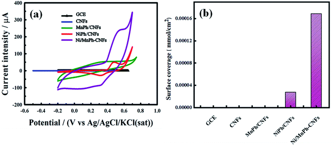
Fig. 7a shows CVs for bare GCE, CNFs, NiPh/CNFs, MnPh/CNFs, and Ni/MnPh-CNFs in 0.25 M KOH at 50 mV s−1 scan rate. Both oxidation and reduction peaks are not appeared in the CV for GCE and CNFs electrodes. MnPh/CNFs electrode exhibits featureless cyclic voltammogram while the charging current of MnPh/CNFs is significantly increased when compared to GCE and CNFs. This increase may be due to the unique characteristic of MnPh and the incorporation between MnPh and CNFs. NiPh/CNFs shows a well-defined redox peak due to the conversion of Ni(II) ⇌ Ni(III). Ni/MnPh-CNFs displays the best redox peak, where the current intensity is higher than the rest of the studied samples. These results confirm the synergistic effect of the bimetallic catalyst.The surface coverage values (Γ) of different electrode materials were determined from the following equation eqn (5);72
 | (5) |
As reported in Table 3, Ni/MnPh-CNFs has the highest value of surface coverage (Γ = 1.690 × 10⁻⁴), which causes an increase of active sites Ni+2/Ni+3 on the surface of Ni/MnPh-CNFs electrode throughout OH− insertion and extraction reactions.
| Material | Γ/mmol cm−2 |
|---|---|
| GCE | 0.00 |
| CNFs | 0.00 |
| MnPh/CNFs | 0.00 |
| NiPh/CNFs | 2.780 × 10⁻⁵ |
| Ni/MnPh-CNFs | 1.690 × 10⁻⁴ |
Fig. 7b represents the comparison of all investigated electrode surface coverage. Based on the findings of surface coverage, the introduction of MnPh plays a significant role to improve the catalytic performance of electrocatalyst that is correlated with increasing the amount of active sites Ni+2/Ni+3.
3.4. Electrochemical oxidation of formaldehyde on Ni/MnPh-CNFs
The performance of the bimetallic phosphates electrode toward formaldehyde electrooxidation is also implemented at different potential scan rates. Fig. 8a displays the CVs curves of electrooxidation of 0.25 M of KOH containing 0.01 M of formaldehyde on the surface of Ni/MnPh-CNFs electrode. The anodic peak current increases with the scan rate. Also, the voltammetric response of Ni/MnPh-CNFs electrode verifies the reproducible oxidation and reduction peaks which being ascribed to the formation of Ni(II)/Ni(III) redox couple at low scan rates. The height of anodic peak currents is approximately Ipa ≃ 255 μA at 5 mV s−1, and 2650 μA at 400 mV s−1 scan rate. Also, the reduction peaks current are progressively increased with increasing the scan rate, indicating the irreversible nature of the formaldehyde oxidation process. Compared to the CV responses of mono NiPh/CNFs, and MnPh/CNFs at similar conditions, CVs for Ni/MnPh-CNFs achieve the highest increase with varied scan rates. The anodic peak currents Ipa versus square root ν0.5 of different potential scan rates are plotted in Fig. 8b. This linear behaviour confirms that the electrocatalytic oxidation of formaldehyde on Ni/MnPh-CNFs electrode is an irreversible controlled process by diffusion that is consistent with Randles–Sevcik equation as described in eqn (6); 77
 | (6) |
 | (7) |
From Fig. 8B, the emanating slope of the straight line is found to be 3.078 that is equal to RT/2αnaF. Thus, the resulting average of α value and Do parameter are estimated to be α = 0.2501 and Do = 1.185 × 10⁻³ cm2 s−1. In addition, the linear dependency of the peak potential Epa on the natural logarithm of potential scan rate ln ν is presented in Fig. 8c. Also, the normalized plot of is initially steeps with low ν/V s−1, then it remains constant at higher potential scan rates (Fig. 8d).
The resulting plot suggests that the electrocatalytic oxidation of formaldehyde follows the regeneration of Ni+2/Ni+3 mechanism on the surface of Ni/MnPh-CNFs electrode. The plot reflects the EC′ mechanism of active species regeneration which obeys the following reactions:
| Ni3(PO4)2/MnPh + OH− ⇌ Ni(III)OOH/ MnPh +H2O + e− | (8) |
| NiOOH/MnPh + CH2(OH)O− → Ni (OH)2/MnPh + CH(O)O− | (9) |
3.5. Effect of formaldehyde concentration
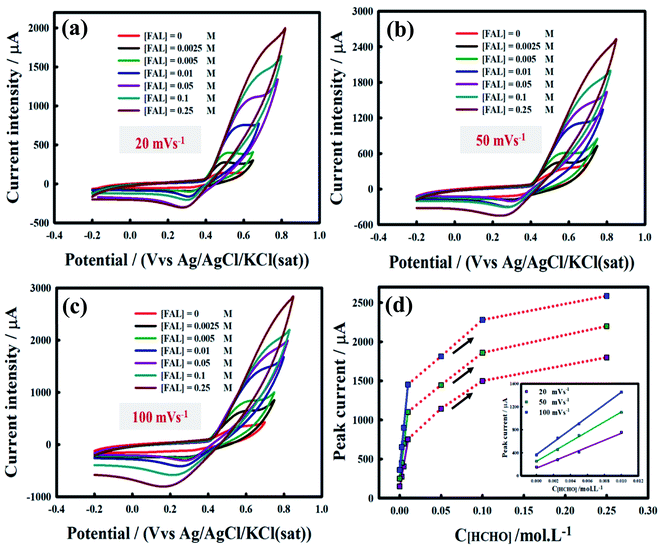
Fig. 9 demonstrates the effect of various formaldehyde concentrations of 0.0025 M, 0.005, 0.01 M, 0.05 M, 0.1 M, and 0.25 M on the CVs for the Ni/MnPh-CNFs. This diagnostic test was carried out at different scan rates of 20 mV s−1, 50 mV s−1, 100 mV s−1 and 200 mV s−1. Fig. 9a, b, and c display the current intensity peaks Ipa increase as the concentration of formaldehyde increase up to 0.25 M. The maximum peaks current are approximately 1800 μA, 2200 μA, and 2585 μA at 20 mV s−1 (Fig. 9a), 50 mV s−1(Fig. 9b), and 100 mV s−1 (Fig. 9c), respectively in 0.25 M KOH containing 0.25 M of formaldehyde. The anodic peak potential is also shifted to more positive direction by increasing the formaldehyde concentration.The inset of Fig. 9d shows the linear plots of Ipa values with low formaldehyde concentrations (0 M → 0.01 M). However, the peak current value is deviated from a straight line and increased with high formaldehyde concentrations (0.05 M, 0.1 M, and 0.25 M). This result gives a clear indication of the activity of bimetallic Ni/MnPh-CNFs electrocatalyst with increasing the concentration of formaldehyde. It may be due to the synergistic effect between NiPh and MnPh and the presence of CNFs, which accelerate the electron transfer and improve the electrical conductivity of materials.
As shown in Fig. S3a,† it can be interestingly noted that the anodic peak current is decreased at a scan rate higher than 100 mV s−1 and formaldehyde concentration higher than 0.01 M. Ipa tends to have different modes, illustrating a limitation in the formaldehyde electrooxidation kinetics. Besides, the anodic peak potential in the forward scan (Epf) shifts to a more positive potential direction. The augmented linear trend of Ipa value at low formaldehyde concentrations (0 M → 0.01 M) is displayed in Fig. S3b† (ESI), while a significant decline was observed at formaldehyde concentration higher than 0.01 M. It is attributed to a large number of saturated active sites by intermediates products resulting from the formaldehyde oxidation process. This phenomenon increases the poisoning extent of catalysts and hampers the diffusion of reactant into the surface of the bimetallic electrocatalyst.
CVs of formaldehyde oxidation recorded 50 mV s−1 for different electrodes are shown in Fig. 10. Uncoated GCE substrate is acted as a charge collector and does not exhibit any surface redox reaction. It is also markedly noted that a similar voltammetric response is observed even after 100% loading of CNFs owing to the defect-free coupled with the surface of CNFs. The conjugation between CNFs and GCE surface provides a higher surface area, electrical conductivity, and charge transfer. However, the CNFs activity toward formaldehyde electrooxidation is not as high as that of other phosphate catalysts. By loading 80% of MnPh material that is physically incorporated with 20 wt% of CNFs, a significant increase in the charging current is observed while no peak could be assigned to oxidation of Mn(II) to a higher valence state. On the other hand, the loading of 80 wt% of NiPh/CNFs leads to an increasing and broadening in the anodic peak current. The anodic and cathodic peaks current are due to the oxidation and reduction of NiPh. Therefore, Ni is changed to a higher valence state in, which causes the formation of redox couple species Ni2+/Ni3+, thus giving rise in the voltammetric response in the electrolyte (0.25 M KOH) containing 0.01 M of formaldehyde. The area of the CV curve is further increased after loading of 80% bimetallic Ni/MnPh-CNFs, which is mainly attributed to the synergistic effect between NiPh and MnPh. Consequently, the charge transfer is accelerated to generate a higher amount of active sites (Ni2+/Ni3+) on the surface for better activity toward formaldehyde electrooxidation. Also, CNFs material improves the electrical conductivity of the catalyst and decreases the internal resistance. Even though the pristine MnPh is electrochemically inactive, bimetallic Ni/MnPh-CNFs electrocatalyst exhibits the highest formaldehyde oxidation peak, which is recorded at 1120 μA at a potential of 0.65 V vs. Ag/AgCl. This response is 3 times higher than that for NiPh/CNFs.
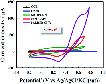 | ||
| Fig. 10 CVs for different electrode materials (GCE, CNFs, MnPh/CNFs, NiPh/CNFs, and Ni/MnPh-CNFs) in 0.01 M KOH containing 0.01 M formaldehyde at 50 mV s−1 scan rate. | ||
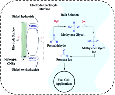
Generally, the proposed mechanism of formaldehyde electrooxidation on bimetallic Ni/MnPh-CNFs can be described by reactions in Fig. 11.
Firstly, formaldehyde is hydrated to methylene glycol, CH2(OH)2 in an alkaline medium. This step is required for the regeneration of the bimetallic catalyst. Keq of the hydration process is 2.28 × 103.78 Then methylene glycol (MG) is ionized during the hydration process. Hence, MG ions, CH2(OH)O− are the dominant species in the formaldehyde aqueous solution. After that, nickel hydroxide Ni (OH)2/nickel oxyhydroxide NiOOH species are formed on the surface of the bimetallic electrode. Consequently, MG ions are diffused from the bulk solution to the electrode surface. Therefore, Ni3+ is chemically reacted with CH2(OH)O− which causes the reduction of Ni3+ species. Then the ions are quickly oxidized to CH(O)O− by the Ni3+ species on the electrode surface and generate one electron.32,72,74,79 MnPh serves as co-catalyst to improve the formation of Ni3+. Subsequently, further formaldehyde electrooxidation is taking place. The oxidation of the formaldehyde process is accelerated by the increasing electrical conductivity provided by CNFs component of the bimetallic-CNFs electrode. This process is referred to as indirect oxidation process which follows the EC′ mechanism.
3.6. Chronoamperometry analysis
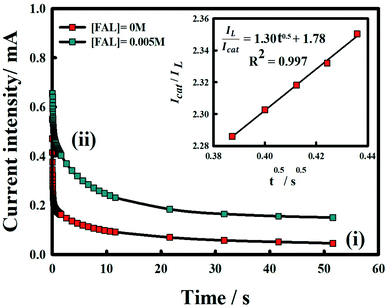
The chronoamperogram of Ni/MnPh-CNFs in 0.25 M KOH in the presence of 0.005 M HCHO at the fixed potential of 0.5 V is shown in Fig. 12. Obviously, the chronoamperogram (i) shows lower current intensity than (ii) that results from the formaldehyde oxidation on the bimetallic-CNFs surface. It is due to a large number of active sites on the surface of bimetallic Ni/MnPh-CNFs electrode, which can lead to a high anodic current response. The catalytic activity of Ni/MnPh-CNFs electrode toward formaldehyde electrooxidation is evaluated by determining the catalytic rate constant (kcat). Fig. 12 inset displays the slope of a straight-line plot of Icat/IL against time/s, which is used to estimate the kcat value according to eqn (10);80
 | (10) |
| Catalyst | Electrolyte | kcat | C[HCHO]/M | Ref. |
|---|---|---|---|---|
| Ni/WO4 NPs | 0.1 M NaOH | 1.37 × 10⁴ | 0.015 | 51 |
| Ni/poly (NMA)-CPE | 0.1 M NaOH | 8.69 × 10⁴ | 0.01 | 81 |
| Ni (OH)2/MIL(Cr)-CPE | 0.1 M NaOH | 2.37 × 10² | — | 15 |
| Ni/ANAZ-CPE | 0.1 M NaOH | 7.56 × 10⁴ | — | 82 |
| Fe/FeZM-CPE | 0.1 M HCl | 7.56 × 10³ | — | 46 |
| Ni–Pd/Si MCP | 1 M KOH | — | 1 | 47 |
| Pd/PPy composite | 0.1 M NaOH | — | — | 48 |
| CuO/Cu/TiO2 nanotube arrays | 0.1 M KOH | 0.00325 | 49 | |
| Ni/MnPh-CNFs | 0.25 M KOH | 1.08 × 10⁵ | 0.005 | This work |
4. Conclusion
In summary, eco-friendly and cost-effective materials, particularly, nickel nitrate hexahydrates, ammonium dibasic phosphate, and manganese acetate were employed to prepare bimetallic Ni/MnPh-via simple reflux co-precipitation. The introduction of MnPh to form bimetallic phosphates of NiPh is a promising approach in increasing the number of accessible active sites Ni2+/Ni3+ of redox reactions during formaldehyde electrooxidation. The electrical conductivity of bimetallic phosphates catalyst was enhanced by carbon nanofibers owing to its high surface area. The overall observation is that the bimetallic Ni/MnPh-CNFs electrocatalyst was characterized by the higher anodic current response, higher charge transfer rate, when benchmarked to characteristics of mono NiPh/CNFs catalyst and toward formaldehyde oxidation because of the synergistic effect between NiPh and MnPh as well as high electrical conductive CNFs. Nickel/manganese phosphates-CNFs achieved salient electrochemical performance for formaldehyde electrooxidation in alkaline solution. Therefore, bimetallic nickel-based catalyst is also expected to be distinguished material for fuel cells, oxygen evolution reaction, hydrogen production, and lithium-ion batteries applications.Conflicts of interest
There are no conflicts to declare.Acknowledgements
This work was supported through the Annual Funding Track by the Deanship of Scientific Research, Vice Presidency for Graduate Studies and Scientific Research, King Faisal University, Saudi Arabia (Project Number NA0004).References
- Q. Lin, Y. Wei, W. Liu, Y. Yu and J. Hu, Electrocatalytic oxidation of ethylene glycol and glycerol on nickel ion implanted-modified indium tin oxide electrode, Int. J. Hydrogen Energy, 2017, 42, 1403–1411 CrossRef CAS.
- A. M. Makin Adam, M. Deng, A. Zhu, Q. Zhang and Q. Liu, Facile one-step room temperature synthesis of PdAg nanocatalysts supported on multi-walled carbon nanotubes towards electro-oxidation of methanol and ethanol, Electrochim. Acta, 2020, 339, 135929 CrossRef CAS.
- V. Latyshev, H. You, A. Kovalcikova and V. Komanicky, Enhancing catalytic activity of rhodium towards methanol electro-oxidation in both acidic and alkaline media by alloying with iron, Electrochim. Acta, 2020, 330, 135178 CrossRef CAS.
- S. Qian, Z. Rao, Y. Liu, J. Yan, B. Fan, Y. Gui and F. Guo, Nickel-Rhodium bimetallic dispersions supported on nickel foam as the efficient catalyst for urea electrooxidation in alkaline medium, Electrochim. Acta, 2020, 330, 135211 CrossRef CAS.
- E. Urbańczyk, A. Maciej, A. Stolarczyk, M. Basiaga and W. Simka, The electrocatalytic oxidation of urea on nickel-graphene and nickel-graphene oxide composite electrodes, Electrochim. Acta, 2019, 305, 256–263 CrossRef.
- S. F. Ho, A. Mendoza-Garcia, S. Guo, K. He, D. Su, S. Liu, Ö. Metin and S. Sun, A facile route to monodisperse MPd (M = Co or Cu) alloy nanoparticles and their catalysis for electrooxidation of formic acid, Nanoscale, 2014, 6, 6970–6973 RSC.
- H. Jiang, L. Liu, K. Zhao, Z. Liu, X. Zhang and S. Hu, Effect of pyridinic- and pyrrolic-nitrogen on electrochemical performance of Pd for formic acid electrooxidation, Electrochim. Acta, 2020, 337, 135758 CrossRef CAS.
- Z. Li, J. Song, D. C. Lee, A. Abdelhafiz, Z. Xiao, Z. Hou, S. Liao, B. DeGlee, M. Liu, J. Zeng and F. M. Alamgir, Mono-disperse PdO nanoparticles prepared via microwave-assisted thermo-hydrolyzation with unexpectedly high activity for formic acid oxidation, Electrochim. Acta., 2020, 329, 135166 CrossRef CAS.
- Y. Chen, X. Liu, W. Zhang, Y. Zhang, L. Li, Z. Cao and H. Wang, Analytical Methods electrodeposited graphene – platinum nanoparticles composites electrode, 2013, 3915–3919 Search PubMed.
- W. Liao, Y. wei Chen, Y. C. Liao, X. yi Lin, S. Yau, J. J. Shyue, S. Y. Wu and H. T. Chen, Low Nickel-doped copper as the electrocatalyst for oxidation of formaldehyde and evolution of hydrogen, Electrochim. Acta, 2020, 333, 135542 CrossRef CAS.
- Š. Trafela, J. Zavašnik, S. Šturm and K. Ž. Rožman, Formation of a Ni(OH)2/NiOOH active redox couple on nickel nanowires for formaldehyde detection in alkaline media, Electrochim. Acta, 2019, 309, 346–353 CrossRef.
- C. Jiang, H. Chen, C. Yu, S. Zhang, B. Liu and J. Kong, Preparation of the Pt nanoparticles decorated poly(N-acetylaniline)/MWNTs nanocomposite and its electrocatalytic oxidation toward formaldehyde, Electrochim. Acta, 2009, 54, 1134–1140 CrossRef CAS.
- Z. Zhou, S. Wang, W. Zhou, G. Wang, L. Jiang, W. Li, S. Song, J. Liu, G. Sun and Q. Xin, Novel synthesis of highly active Pt/C cathode electrocatalyst for direct methanol fuel cell, Chem. Commun., 2003, 3, 394–395 RSC.
- S. R. Hosseini, J. B. Raoof, S. Ghasemi and Z. Gholami, Pd-Cu/poly(o-Anisidine) nanocomposite as an efficient catalyst for formaldehyde oxidation, Mater. Res. Bull., 2016, 80, 107–119 CrossRef CAS.
- S. Gheytani and M. Taherimehr, Formaldehyde Electro-catalytic Oxidation onto Carbon Paste Electrode Modified by MIL-101 ( Cr ) Nanoparticles, Fuel Cells, 2019, 101, 1–14 Search PubMed.
- H. M. Villullas, F. I. Mattos-Costa, P. A. P. Nascente and L. O. S. Bulhões, Anodic oxidation of formaldehyde on Pt-modified SnO2 thin film electrodes prepared by a sol-gel method, Electrochim. Acta, 2004, 49, 3909–3916 CrossRef CAS.
- H. Xiang, H. A. Miller, M. Bellini, H. Christensen, K. Scott, S. Rasul and E. H. Yu, Production of formate by CO2 electrochemical reduction and its application in energy storage, Sustainable Energy Fuels, 2019, 4, 277–284 RSC.
- H. Hwang, S. Hong, J. W. Kim and J. Lee, Optimized Electrode Structure for Performance and Mechanical Stability in Direct Formate Fuel Cell using Cation Ionomer, Sustainable Energy Fuels, 2020, 4, 1899–1907 RSC.
- J. Hong, W. Zhang, J. Ren and R. Xu, Photocatalytic reduction of CO2: a brief review on product analysis and systematic methods, R. Soc. Chem., 2013, 11, 2945–3054 Search PubMed.
- D. TrivediJ, J. Crosse, J. Tanti, A. J. Cass and K. E. Toghill, The electrochemical determination of formaldehyde in aqueous media using nickel modified electrodes, Sens. Actuators, B, 2018, 270, 298–303 CrossRef CAS.
- J. Qiao, J. Chang, H. Wang, T. Sun and C. Dong, Determination of Formaldehyde with a Platinum–Palladium–Graphene Nanocomposite Glassy Carbon Electrode, Anal. Lett., 2017, 50, 80–90 CrossRef CAS.
- G. Y. Gao, D. J. Guo and H. L. Li, Electrocatalytic oxidation of formaldehyde on palladium nanoparticles supported on multi-walled carbon nanotubes, J. Power Sources, 2006, 162, 1094–1098 CrossRef CAS.
- V. Selvaraj, M. Alagar and K. S. Kumar, Synthesis and characterization of metal nanoparticles-decorated PPY-CNT composite and their electrocatalytic oxidation of formic acid and formaldehyde for fuel cell applications, Appl. Catal., B, 2007, 75, 129–138 CrossRef CAS.
- E. A. Batista and T. Iwasita, Adsorbed intermediates of formaldehyde oxidation and their role in the reaction mechanism, Langmuir, 2006, 22, 7912–7916 CrossRef CAS PubMed.
- S. J. Marje, P. K. Katkar, S. B. Kale, A. C. Lokhande, C. D. Lokhande and U. M. Patil, Effect of phosphate variation on morphology and electrocatalytic activity (OER) of hydrous nickel pyrophosphate thin films, J. Alloys Compd., 2019, 779, 49–58 CrossRef CAS.
- Y. Tang, Z. Liu, W. Guo, T. Chen, Y. Qiao, S. Mu, Y. Zhao and F. Gao, Honeycomb-like mesoporous cobalt nickel phosphate nanospheres as novel materials for high performance supercapacitor, Electrochim. Acta, 2016, 190, 118–125 CrossRef CAS.
- C. V Ramana, S. Utsunomiya, U. Becker, A. Mauger, F. Gendron, C. M. Julien, A. Arbor, N. D. P. Insp, V. Uni, M. Curie, D. Lourmel, R. V May, V. Re, M. Recei and V. June, Structural Characteristics of Lithium Nickel Phosphate Studied Using Analytical Electron Microscopy and Raman Spectroscopy, Chem. Mater., 2006, 18, 3788–3794 CrossRef.
- S. K. Hassaninejad-Darzi and M. Gholami-Esfidvajani, Preparation of nanoporous nickel phosphate VSB-5 nanorods carbon paste electrode as glucose non-enzymatic sensor, J. Porous Mater., 2017, 24, 85–95 CrossRef CAS.
- M. A. Al-Omair, A. H. Touny and M. M. Saleh, Reflux-based synthesis and electrocatalytic characteristics of nickel phosphate nanoparticles, J. Power Sources, 2017, 342, 1032–1039 CrossRef CAS.
- A. H. Touny and M. M. Saleh, Enhanced methanol oxidation on nanoporous nickel phosphate modified platinum electrode in alkaline solution, Int. J. Electrochem. Sci., 2018, 13, 1042–1050 CrossRef CAS.
- M. A. Al-Omair, A. H. Touny, F. A. Al-Odail and M. M. Saleh, Electrocatalytic Oxidation of Glucose at Nickel Phosphate Nano/Micro Particles Modified Electrode, Electrocatalysis, 2017, 8, 340–350 CrossRef CAS.
- A. H. Touny, R. H. Tammam and M. M. Saleh, Electrocatalytic oxidation of formaldehyde on nanoporous nickel phosphate modified electrode, Appl. Catal., B, 2018, 224, 1017–1026 CrossRef CAS.
- R. Chong, B. Wang, D. Li, Z. Chang and L. Zhang, Enhanced photoelectrochemical activity of Nickel-phosphate decorated phosphate-Fe2O3 photoanode for glycerol-based fuel cell, Sol. Energy Mater. Sol. Cells, 2017, 160, 287–293 CrossRef CAS.
- J. H. Yang, X. Song, X. Zhao, Y. Wang, Y. Yang and L. Gao, Nickel phosphate materials regulated by doping cobalt for urea and methanol electro-oxidation, Int. J. Hydrogen Energy, 2019, 44, 16305–16314 CrossRef CAS.
- H. I. Hsiang, L. T. Mei and Y. H. Lin, Formation and growth of manganese phosphate passivation layers for NTC ceramics, J. Alloys Compd., 2009, 484, 723–728 CrossRef CAS.
- Y. Bai, M. Liu, J. Sun and L. Gao, Fabrication of Ni-Co binary oxide/reduced graphene oxide composite with high capacitance and cyclicity as efficient electrode for supercapacitors, Ionics, 2016, 22, 535–544 CrossRef CAS.
- J. Zhang, F. Liu, J. P. Cheng and X. B. Zhang, Binary Nickel-Cobalt Oxides Electrode Materials for High-Performance Supercapacitors: Influence of its Composition and Porous Nature, ACS Appl. Mater. Interfaces, 2015, 7, 17630–17640 CrossRef CAS PubMed.
- G. D. Park, S. J. Yang, J. H. Lee and Y. C. Kang, Investigation of Binary Metal (Ni, Co) Selenite as Li-Ion Battery Anode Materials and Their Conversion Reaction Mechanism with Li Ions, Small, 2019, 15, 1–17 Search PubMed.
- R. Elakkiya and G. Maduraiveeran, A three-dimensional nickel-cobalt oxide nanomaterial as an enzyme-mimetic electrocatalyst for the glucose and lactic acid oxidation reaction, New J. Chem., 2019, 43, 14756–14762 RSC.
- N. A. M. Barakat, M. H. El-Newehy, A. S. Yasin, Z. K. Ghouri and S. S. Al-Deyab, Ni&Mn nanoparticles-decorated carbon nanofibers as effective electrocatalyst for urea oxidation, Appl. Catal., A, 2016, 510, 180–188 CrossRef CAS.
- M. K. Nazal, O. S. Olakunle, A. Al-Ahmed, A. S. Sultan and S. J. Zaidi, Methanol Electro-Oxidation in Alkaline Medium by Ni Based Binary and Ternary Catalysts: Effect of Iron (Fe) on the Catalyst Performance, Russ. J. Electrochem., 2019, 55, 61–69 CrossRef CAS.
- T. Rostami, M. Jafarian, S. Miandari, M. G. Mahjani and F. Gobal, Synergistic effect of cobalt and copper on a nickel-based modified graphite electrode during methanol electro-oxidation in NaOH solution, Chin. J. Catal., 2015, 36, 1867–1874 CrossRef CAS.
- R. H. Tammam, A. M. Fekry and M. M. Saleh, Electrocatalytic oxidation of methanol on ordered binary catalyst of manganese and nickel oxide nanoparticles, Int. J. Hydrogen Energy, 2015, 40, 275–283 CrossRef CAS.
- D. Chen, S. Pei, Z. He, H. Shao, J. Wang, K. Wang, Y. Wang and Y. Jin, High active pdsn binary alloyed catalysts supported on B and N codoped graphene for formic acid electro-oxidation, Catalysts, 2020, 10, 751 CrossRef CAS.
- J. Yang, Y. Xie, R. Wang, B. Jiang, C. Tian, G. Mu, J. Yin, B. Wang and H. Fu, Synergistic effect of tungsten carbide and palladium on graphene for promoted ethanol electrooxidation, ACS Appl. Mater. Interfaces, 2013, 5, 6571–6579 CrossRef CAS PubMed.
- M. Abrishamkar and M. Barootkoob, Electrooxidation of formaldehyde as a fuel for fuel cells using Fe2+-nano-zeolite modified carbon paste electrode, Int. J. Hydrogen Energy, 2017, 42, 23821–23825 CrossRef CAS.
- F. Miao and B. Tao, Electrooxidation of formaldehyde based on nickel-palladium modified ordered mesoporous silicon, J. Nanosci. Nanotechnol., 2013, 13, 3104–3109 CrossRef CAS PubMed.
- K. V. Gor’kov, N. V. Talagaeva, S. A. Kleinikova, N. N. Dremova, M. A. Vorotyntsev and E. V. Zolotukhina, Palladium-polypyrrole composites as prospective catalysts for formaldehyde electrooxidation in alkaline solutions, Electrochim. Acta, 2020, 345, 1–10 CrossRef.
- S. Zhang, X. Wen, M. Long, J. Xi, J. Hu and A. Tang, Fabrication of CuO/Cu/TiO2 nanotube arrays modified electrode for detection of formaldehyde, J. Alloys Compd., 2020, 829, 154568 CrossRef CAS.
- J. Biemolt, D. van Noordenne, J. Liu, E. Antonetti, M. Leconte, S. van Vliet, R. Bliem, G. Rothenberg, X. Z. Fu and N. Yan, Assembling palladium and cuprous oxide nanoclusters into single quantum dots for the electrocatalytic oxidation of formaldehyde, ethanol, and glucose, ACS Appl. Nano Mater., 2020, 3, 10176–10182 CrossRef CAS.
- S. Daemi, M. Moalem-Banhangi, S. Ghasemi and A. A. Ashkarran, An efficient platform for the electrooxidation of formaldehyde based on amorphous NiWO4 nanoparticles modified electrode for fuel cells, J. Electroanal. Chem., 2019, 848, 113270 CrossRef CAS.
- H. Huang and X. Wang, Recent progress on carbon-based support materials for electrocatalysts of direct methanol fuel cells, J. Mater. Chem. A, 2014, 2, 6266–6291 RSC.
- J. Wei, Y. Liu, Y. Ding, C. Luo, X. Du and J. Lin, MnO2 spontaneously coated on carbon nanotubes for enhanced water oxidation, Chem. Commun., 2014, 50, 11938–11941 RSC.
- D. Ye, T. Wu, H. Cao, Y. Wang, B. Liu, S. Zhang and J. Kong, Electrocatalysis of both oxygen reduction and water oxidation using a cost-effective three-dimensional MnO2/graphene/carbon nanotube, RSC Adv., 2015, 5, 26710–26715 RSC.
- N. A. M. Barakat, M. T. Amen, F. S. Al-Mubaddel, M. R. Karim and M. Alrashed, NiSn nanoparticle-incorporated carbon nanofibers as efficient electrocatalysts for urea oxidation and working anodes in direct urea fuel cells, J. Adv. Res., 2019, 16, 43–53 CrossRef CAS PubMed.
- R. K. Singh and A. Schechter, Electroactivity of NiCr Catalysts for Urea Oxidation in Alkaline Electrolyte, ChemCatChem, 2017, 9, 3374–3379 CrossRef CAS.
- M. F. R. Hanifah, J. Jaafar, M. H. D. Othman, A. F. Ismail, M. A. Rahman, N. Yusof, F. Aziz and N. A. Rahman, One-pot synthesis of efficient reduced graphene oxide supported binary Pt-Pd alloy nanoparticles as superior electro-catalyst and its electro-catalytic performance toward methanol electro-oxidation reaction in direct methanol fuel cell, J. Alloys Compd., 2019, 793, 232–246 CrossRef CAS.
- K. Kakaei and K. Marzang, One - Step synthesis of nitrogen doped reduced graphene oxide with NiCo nanoparticles for ethanol oxidation in alkaline media, J. Colloid Interface Sci., 2016, 462, 148–153 CrossRef CAS PubMed.
- A. H. Touny, R. H. Tammam and M. M. Saleh, Electrocatalytic oxidation of formaldehyde on nanoporous nickel phosphate modified electrode, Appl. Catal., B, 2018, 224, 1017–1026 CrossRef CAS.
- M. E. Abdelsalam, I. Elghamry, A. H. Touny and M. M. Saleh, Nickel phosphate/carbon fibre nanocomposite for high-performance pseudocapacitors, J. Appl. Electrochem., 2019, 49, 45–55 CrossRef CAS.
- S. R. Dhakate, A. Chaudhary, A. Gupta, A. K. Pathak, B. P. Singh, K. M. Subhedar and T. Yokozeki, Excellent mechanical properties of carbon fiber semi-aligned electrospun carbon nanofiber hybrid polymer composites, RSC Adv., 2016, 6, 36715–36722 RSC.
- H. McMurdie, M. Morris, E. Evans, B. Paretzkin, W. Wong-NG and Hubbard, Methods of Producing Standard X-Ray Diffraction Powder Patterns, Powder Diffraction, 1986, 1, 40–43 CrossRef CAS.
- T. Arfin, A. Falch and R. J. Kriek, Evaluation of charge density and the theory for calculating membrane potential for a nano-composite nylon-6,6 nickel phosphate membrane, Phys. Chem. Chem. Phys., 2012, 14, 16760–16769 RSC.
- A. A. Al-Sultan, M. M. Saleh and A. H. Touny, Direct and indirect electrocatalysis on nickel phosphate-based catalysts, J. Electroanal. Chem., 2019, 844, 116–123 CrossRef CAS.
- X. Xu, X. Song, X. Liu, H. Wang, Y. Hu, J. Xia, J. Chen, M. Shakouri, Y. Guo and Y. Wang, A highly efficient nickel phosphate electro-catalyst for the oxidation of 5-hydroxymethylfurfural to 2, 5-furandicarboxylic acid, ACS Sustainable Chem. Eng., 2022, 10, 5538–5547 CrossRef CAS.
- E. S. Ilton, J. E. Post, P. J. Heaney, F. T. Ling and S. N. Kerisit, XPS determination of Mn oxidation states in Mn (hydr)oxides, Appl. Surf. Sci., 2016, 366, 475–485 CrossRef CAS.
- A. Irshad and N. Munichandraiah, Ir-phosphate cocatalyst for photoelectrochemical water oxidation using α-Fe2O3, RSC Adv., 2017, 7, 21430–21438 RSC.
- K. A. Cychosz, R. Guillet-Nicolas, J. García-Martínez and M. Thommes, Recent advances in the textural characterization of hierarchically structured nanoporous materials, Chem. Soc. Rev., 2017, 46, 389–414 RSC.
- L. Kong and W. Chen, Ionic Liquid Directed Mesoporous Carbon Nanoflakes as an Efficient Electrode material, Sci. Rep., 2015, 5, 1–9 Search PubMed.
- K. A. Cychosz, R. Guillet-Nicolas, J. García-Martínez and M. Thommes, Recent advances in the textural characterization of hierarchically structured nanoporous materials, Chem. Soc. Rev., 2016, 46, 389–414 RSC.
- S. Kavian, S. N. Azizi and S. Ghasemi, Fabrication of novel nanozeolite-supported bimetallic Pt[sbnd]Cu nanoparticles modified carbon paste electrode for electrocatalytic oxidation of formaldehyde, Int. J. Hydrogen Energy, 2016, 41, 14026–14035 CrossRef CAS.
- S. A. Al-Jendan, W. Alarjan, I. Elghamry, A. Touny, M. M. Saleh and M. E. Abdelsalam, An optimized nickel phosphate/carbon composite electrocatalyst for the oxidation of formaldehyde, Int. J. Hydrogen Energy, 2020, 45, 14320–14333 CrossRef CAS.
- E. Laviron, General expression of the linear potential sweep voltammogram in the case of diffusionless electrochemical systems, J. Electroanal. Chem., 1979, 101, 19–28 CrossRef CAS.
- S. K. Hassaninejad-Darzi, M. Rahimnejad and M. Golami-Esfidvajani, Electrocatalytic Oxidation of Formaldehyde onto Carbon Paste Electrode Modified with Nickel Decorated Nanoporous Cobalt-Nickel Phosphate Molecular Sieve for Fuel Cell, Fuel Cells, 2016, 16, 89–99 CrossRef CAS.
- S. K. Hassaninejad-Darzi, A novel, effective and low cost catalyst for formaldehyde electrooxidation based on nickel ions dispersed onto chitosan-modified carbon paste electrode for fuel cell, J. Electroceram., 2014, 33, 252–263 CrossRef CAS.
- S. Kavian, S. N. Azizi and S. Ghasemi, Preparation of a novel supported electrode comprising a nickel (II) hydroxide-modified carbon paste electrode (Ni(OH)2-X/CPE) for the electrocatalytic oxidation of formaldehyde, Chin. J. Catal., 2016, 37, 159–168 CrossRef CAS.
- A. J. B. La and L. R. Faulkner, Electrochemical methods, fundamentals and applications, John Wily & Sons, Inc, New York, 2nd ed., 2001, vol. 60 Search PubMed.
- S. Naser, S. Ghasemi and F. Amiripour, Sensors and Actuators B : Chemical Nickel/P nanozeolite modified electrode : A new sensor for the detection of formaldehyde, Sens. Actuators, B, 2016, 227, 1–10 CrossRef.
- J. B. Raoof, R. Ojani, S. Abdi and S. R. Hosseini, Highly improved electrooxidation of formaldehyde on nickel/poly (o-toluidine)/Triton X-100 film modified carbon nanotube paste electrode, Int. J. Hydrogen Energy, 2012, 37, 2137–2146 CrossRef CAS.
- H. Luo, Z. Shi, N. Li, Z. Gu and Q. Zhuang, Investigation of the electrochemical and electrocatalytic behavior of single-wall carbon nanotube film on a glassy carbon electrode, Anal. Chem., 2001, 73, 915–920 CrossRef CAS PubMed.
- J. B. Raoof, A. Omrani, R. Ojani and F. Monfared, Poly(N-methylaniline)/nickel modified carbon paste electrode as an efficient and cheep electrode for electrocatalytic oxidation of formaldehyde in alkaline medium, J. Electroanal. Chem., 2009, 633, 153–158 CrossRef CAS.
- S. N. Azizi, S. Ghasemi and M. Derakhshani-mansoorkuhi, The synthesis of analcime zeolite nanoparticles using silica extracted from stem of sorghum Halepenesic ash and their application as support for electrooxidation of formaldehyde, Int. J. Hydrogen Energy, 2016, 41, 21181–21192 CrossRef CAS.
Footnote |
| † Electronic supplementary information (ESI) available. See https://doi.org/10.1039/d2ra03359c |
| This journal is © The Royal Society of Chemistry 2022 |

