 Open Access Article
A doping-adsorption-pyrolysis strategy for constructing atomically dispersed cobalt sites anchored on a N-doped carbon framework as an efficient bifunctional electrocatalyst for hydrogen evolution and oxygen reduction†
Yuan Pan *ab,
Minmin Wangb and
Chao Feng*b
aEngineering Research Center for Waste Oil Recovery Technology and Equipment, Ministry of Education, Chongqing Technology and Business University, Chongqing 400067, China. E-mail: panyuan@upc.edu.cn; fch_upc@163.com
bState Key Laboratory of Heavy Oil Processing, China University of Petroleum (East China), Qingdao 266580, Shandong, China
First published on 15th July 2022
Abstract
Renewable energy technology development focuses on the exploration of economical and efficient non-precious metal catalysts to replace precious metal catalysts in electrocatalytic reactions including oxygen reduction (ORR) and hydrogen evolution (HER). Herein, we synthesized a cobalt single atom catalyst anchored on a N-doped carbon framework by a doping-adsorption-pyrolysis strategy. The optimized Co SAs/CN-3 catalyst showed excellent HER and ORR bifunctional electrocatalytic performance, which could be attributed to the highly dispersed Co–N4 active sites, large specific surface area and abundant pore structure. Density functional theory shows that the isolated active Co–N4 site shows low hydrogen adsorption Gibbs free energy, and promotes the adsorption of H and oxygen-containing intermediates in HER and ORR. This work not only provides a new idea for the construction of transition metal catalysts with atomic accuracy but also provides powerful guidance for the development of efficient bifunctional electrocatalysts.
Introduction
Hydrogen evolution reactions (HER) and oxygen reduction reactions (ORR) are important in energy conversion processes such as electrocatalytic water splitting, fuel cells, and metal–air batteries, and are essential to facilitate the transition to an environmentally friendly society.1–4 What hinders the development of commercial applications for HER and ORR is their slow kinetics, which still requires precious metals such as Pt, Ru, and Ir as catalysts for efficient conversion.5–10 However, noble metal catalysts have inevitable disadvantages: high cost, scarcity, and poor long-term durability. Therefore, it is very important to develop non-noble metal catalysts with low price, high activity and high stability to improve the development of HER and ORR.In recent years, single-atom catalysts (SACs) have attracted extensive attention because of their maximum utilization of metal atoms and high catalytic activity, among which the Co–N–C catalyst has become one of the most promising alternatives to noble metal catalysts.11–16 Liu et al.17 reported the origin of Co SAC activity in HER by combining experimental and theoretical calculations. The density functional theory (DFT) calculation results show that Co SAs located at the edge of graphene are the highly active sites of HER. Zhang et al.18 anchored single Co atoms on hollow carbon spheres co-doped with N and S as an efficient and multi-functional SAC. Experimental characterizations and theoretical mechanism studies revealed that the synergistic effect between atomically dispersed Co–N4 active sites and nearby electron donor S significantly reduced the potential barrier of the electrocatalytic reaction and improved the reaction activity. However, currently reported Co SACs still existing low intrinsic activity and the number of active sites, and most of them are single-functional catalysts. The bifunctional Co SACs with both high HER and ORR performance is rarely reported. Besides, due to the easy agglomeration of single atoms, the preparation of single atoms catalysts with high loading is difficult to achieve. There are still some challenges in the macroscopic synthesis of single atoms catalysts. Therefore, developing efficient synthesis methods is still a challenge in current research.
In this paper, a nitrogen-doped carbon Co single atoms catalyst (Co SAs/CN-3) with a high specific surface area (846 m2 g−1) was prepared by doping-adsorption-pyrolysis method using metal–organic framework derivatives as precursors. The stable Co–N4 single atom coordination structure was determined by aberration-corrected high-angle annular dark-field scanning transmission electron microscopy (AC-HAADF-STEM) and X-ray absorption spectroscopy (XAS). DFT results show that the isolated Co–N4 active site shows low Gibbs free energy, and promotes the adsorption of H and oxygen-containing intermediates in HER and ORR. The Co SAs/CN-3 catalyst showed excellent HER and ORR bifunctional electrocatalytic performance. In this paper, we provide an efficient bifunctional catalyst and a research idea for the design and synthesis of SACs.
Results and discussion
As shown in Fig. 1a, we developed a novel doping-adsorption-pyrolysis method to synthesize Co single atom catalyst. Firstly, Co2+ is introduced in the preparation of ZIF-8. Since Co2+ and Zn2+ have a similar atomic radius and the same chemical state, Co2+ can occupy the position of Zn2+ and construct the mixed binary ZIF-8 structure (ZnCo@ZIF-8). Zn can act as a steric hindrance and effectively avoid the aggregation of Co atoms. Then, a layer of tetrapenylporphyrin cobalt molecules was adsorbed on the surface of ZnCo@ZIF-8 by π–π conjugation to increase the cobalt load. Finally, ZIF-8 was carbonized to form a nitrogen-doped carbon skeleton through high-temperature pyrolysis. Zn volatilizes at high temperature, and Co atoms are anchored by N atoms to obtain Co single atom catalyst with a stable Co–N4 coordination structure (Co SAs/CN-3).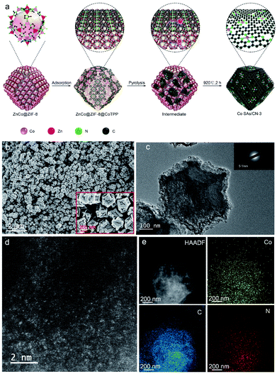 | ||
| Fig. 1 (a) Schematic illustration of the synthesis process of Co SAs/CN-3, (b) SEM, (c) TEM (the inset is SAED image), (d) AC-HAADF-STEM, (e) HAADF-STEM and EDS mapping. | ||
X-ray powder diffraction patterns (XRD) showed wide peaks at ∼25° and ∼44° respectively, indicating the formation of graphite-carbon structure and high dispersion of Co atoms (Fig. S1†).19,20 Inductively coupled plasma mass spectrometry (ICP-OES) results showed that Co loading in Co SAs/CN-3 reached 1.03 wt%, which was much higher than that of Co SAs/CN-1 prepared by first doping (0.37 wt%). The above shows that the doping-adsorption-pyrolysis method can effectively improve the metal loading. TEM and SEM images showed that the prepared Co SAs/CN-3 retained the rhombohedron shape and size of the ZIF-8 precursor without obvious particles (Fig. 1b and c). The selected area electron diffraction (SAED) diagram shows that the crystallinity of Co SAs/CN-3 catalyst is poor. In the high-resolution TEM image, there are only lattice stripes of C, but no lattice stripes of Co, indicating that Co atoms are highly dispersed (Fig. S2†). Many isolated bright spots can be observed in the aberration-corrected high-angle annular dark-field scanning transmission electron microscopy (AC-HAADF-STEM) of Co SAs/CN-3 catalyst, indicating that Co disperses uniformly in the form of single atoms (Fig. 1d). EDS mapping shows that Co, N and C atoms are evenly distributed (Fig. 1e).
The X-ray photoelectron spectroscopy (XPS) results confirm the existence of C, N, and Co in the Co SAs/CN-3 catalyst. The peak at 780.1 eV and 795.5 eV in Co 2p spectrum of Co SAs/CN-3 is assigned to Co2+ (Fig. S3a†).21 The XPS spectrum of N 1s is divided into four peaks, corresponding to pyridinic N (398.5 eV), Co–N (399.5 eV), pyrrolic N (400.2 eV) and graphitic N (401.6 eV), respectively (Fig. S3b†).21 The presence of nitrogen species provides abundant anchoring sites for Co single atoms. The spectrum of C 1s XPS is divided into three peaks with different binding energies, corresponding to the characteristic peaks of C–N (288.1 eV), C![[double bond, length as m-dash]](https://www.rsc.org/images/entities/char_e001.gif) N (285.5 eV) and C
N (285.5 eV) and C![[double bond, length as m-dash]](https://www.rsc.org/images/entities/char_e001.gif) C (284.3 eV), respectively (Fig. S3c†).22,23
C (284.3 eV), respectively (Fig. S3c†).22,23
The pore structure and surface area of Co SAs/CN-3 and Co SAs/CN-1 were analyzed by the N2 adsorption/desorption (Fig. S4 and S5†). The N2 adsorption/desorption curve of Co SAs/CN-3 belongs to the type IV isotherm, indicating abundant pore structure. Co SAs/CN-3 has the highest BET surface area, up to 846 m2 g−1, which is higher than that of Co SAs/CN-1 (314 m2 g−1). In addition, Co SAs/CN-1 and Co SAs/CN-3 have a pore volume of 0.07 and 0.36 cm3 g−1 and average pore size of 1.78 and 1.67 nm, respectively. The above results indicate that the doping-adsorption-pyrolysis method can improve the BET surface area of catalysts and expose more active sites. Raman spectra also confirmed that the ID/IG value of Co SAs/CN-3 catalyst is 1.23, which is significantly higher than that of Co SAs/CN-1 catalyst (1.02), indicating the abundant defects of the Co SAs/CN-3 catalyst. The highly dispersed porous structure can improve catalytic efficiency by facilitating mass transfer between reactants and products.24
The local environment and electronic structure of Co were further studied by X-ray absorption near edge structure (XANES) and extended X-ray absorption fine structure spectrum (EXAFS) (Fig. 3).25–28 The position of K-edge of Co SAs/CN-3 shows that the Co atom has a positive valence, and its valence state is between 0 and +3 (Fig. 2a). The FT k3 weighted EXAFS spectrum of Co SAs/CN-3 catalyst has a main peak at 1.5 Å, belonging to the Co–N coordination, and no Co–Co bond is found at 2.2 Å, indicating that Co is single atomically dispersed (Fig. 2b). The wavelet transform of Co SAs/CN-3 only has a maximum intensity at 4 Å−1, corresponding to the Co–N coordination, which further proves that Co is single-atomic dispersed in Co SAs/CN-3 catalyst (Fig. 3e). By EXAFS fitting, the Co–N coordination of Co SAs/CN-3 catalyst is 4 (Fig. 3c and d).
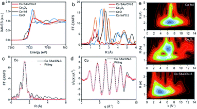 | ||
| Fig. 2 (a) XANES of Co K-edge, (b) Fourier transform (FT) spectra, EXAFS fitting (c) in R space, (d) in q space, (e) WT contour plots. | ||
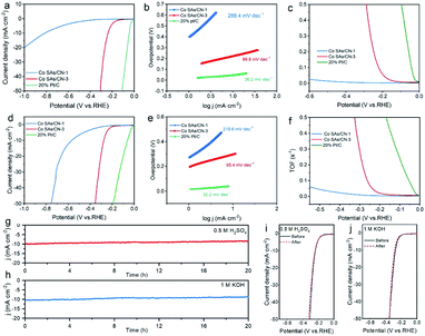
The Co SAs/CN-3 catalyst obtained through a series of optimization experiments has the best electrocatalytic performance of HER (Fig. S6†). When the current density is 10 mA cm−2, Co SAs/CN-3 catalyst needs overpotentials of 238 and 278 mV in 0.5 M H2SO4 and 1 M KOH, respectively, which are lower than that of Co SAs/CN-1 catalyst (810 and 568 mV) (Fig. 3a and d). As shown in Fig. 3b and e, Co SAs/CN-3 catalyst has the lowest Tafel slope of 89.8 mV dec−1 and 95.4 mV dec−1 in 0.5 M H2SO4 and 1 M KOH, respectively. The Tafel slopes of Co SAs/CN-1 catalyst are 288.4 and 218.6 mV dec−1, respectively. The Tafel slope not only indicates that Co SAs/CN-3 catalyst has the highest efficiency of electrocatalytic hydrogen production, but also indicates that the speed control step of Co SAs/CN-3 catalyst is Volmer step, and the electrocatalytic HER complies with Volmer–Heyrovsky mechanism.29,30 The Cdl of Co SAs/CN-3 catalyst are 20.4 mF cm−2 in 0.5 M H2SO4 and 25.1 mF cm−2 in 1 M KOH, which is much higher than that of Co SAs/CN-1 catalyst, indicating that it has a higher electrocatalytic active surface area (Fig. S7†). Co SAs/CN-3 catalyst has the minimum impedance radius in 0.5 M H2SO4 (0.4 V vs. Ag/AgCl) and 1 M KOH (1.4 V vs. SCE), indicating that it has the lowest charge transfer resistance and the fastest electron transfer speed (Fig. S8†).
TOF was used to further explore the intrinsic catalytic activity of Co SAs/CN-3 catalyst. When the overpotential is 300 mV, the TOF of Co SAs/CN-3 is 0.64 s−1 in 0.5 M H2SO4, which is higher than that of Co SAs/CN-1 (∼0 s−1). In 1 M KOH, Co SAs/CN-3 has the highest TOF value of 0.32 s−1 (at 300 mV), which proves that Co SAs/CN-3 catalyst has high intrinsic activity (Fig. 3c and f). After 1000 cycles, the LSV curve in 0.5 M H2SO4 and 1 M KOH basically did not change, reflecting the excellent electrochemical cycling stability of Co SAs/CN-3 catalyst (Fig. 3i and j). As can be seen from the AC-HAADF-STEM image (Fig. S13†), Co atoms are still uniformly dispersed in the form of single atoms on the surface of the substrate after the stability test. After the stability test, the valence state of Co element does not change significantly, and there are still characteristic peaks at about 780.1 eV and 795.5 eV that are attributed to Co2+, and the peak position is not shifted, indicating that Co SAs/CN-3 catalyst has excellent stability. After continuous testing for 20 h, the current density showed a small decrease, which further proved that the catalyst has excellent long-term stability (Fig. 3g and h).
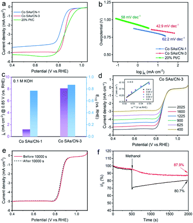
In addition, Co SAs/CN-3 catalyst showed excellent ORR performance in 0.1 M KOH electrolyte saturated with O2 (Fig. 4 and S9–S11†). LSV curve shows that the half-wave potential of Co SAs/CN-3 catalyst is 0.87 V, only 0.1 V lower than that of 20% Pt/C catalyst (0.88 V), but better than Co SAs/CN-1 (0.77 V) (Fig. 4a and c). The Tafel slope of Co SAs/CN-3 was 42.9 mV dec−1, which was significantly lower than that of 20% Pt/C catalyst (59.0 mV dec−1) and Co SAs/CN-1 (62.2 mV dec−1) (Fig. 4b). At the potential of 0.85 V, the jk of Co SAs/CN-3 is 8.1 mA cm−2, and the jk of Co SAs/CN-1 catalysts is 1.2 mA cm−2, respectively, indicating that Co SAs/CN-3 has higher ORR catalytic efficiency (Fig. 4c and S8†). According to the K–L equation, the electron transfer number of Co SAs/CN-3 is about 4, which proves that Co SAs/CN-3 is an efficient 4-electron ORR catalytic process (Fig. 4d). RRDE test results also showed that the electron transfer number of Co SAs/CN-3 was about 4, and the hydrogen peroxide yield was almost zero, confirming again that Co SAs/CN-3 was an effective 4e− ORR catalyst (Fig. S10†). In addition, Co SAs/CN-3 showed excellent stability, with its LSV curve almost unchanged after the i–t test of 10![[thin space (1/6-em)]](https://www.rsc.org/images/entities/char_2009.gif) 000 s (Fig. 4e). It can be seen from the i–t curve that the current retention rate of Co SAs/CN-3 is 77.6% after 12 h stability test (Fig. S12†). Co SAs/CN-3 also had good methanol tolerance, and it still had 87.9% current retention rate at 2000 s. However, the current density of 20% Pt/C decreased significantly after methanol was added at 500 s, and its current retention rate was only 80.7% (Fig. 4f).
000 s (Fig. 4e). It can be seen from the i–t curve that the current retention rate of Co SAs/CN-3 is 77.6% after 12 h stability test (Fig. S12†). Co SAs/CN-3 also had good methanol tolerance, and it still had 87.9% current retention rate at 2000 s. However, the current density of 20% Pt/C decreased significantly after methanol was added at 500 s, and its current retention rate was only 80.7% (Fig. 4f).
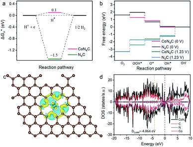
The DFT calculations were carried out to obtain a deep understanding of the excellent electrocatalytic activity of Co SAs/CN-3 catalyst. The control model of N4C was built for comparison with CoN4C (Fig. S14a†). For HER, the Gibbs free energy (ΔGH*) of hydrogen adsorption is closer to 0 eV, indicating that the catalyst has the optimal HER catalytic activity.31 The negative ΔGH* (−1.5 eV) value of N4C indicates a relatively strong hydrogen adsorption, which is not conducive to HER. The ΔGH* value of Co SAs/CN-3 catalyst can be reduced to 0.1 eV (Fig. 5a), indicating that Co SAs/CN-3 is conducive for H2 generation, but the adsorption ability of H* is relatively insufficient, which is consistent with the best HER catalytic activity. In other words, Co SAs/CN-3 has a more suitable ΔGH* for HER. Fig. 5b shows the calculated free-energy image for 4e− reduction pathway of ORR in 0.1 M KOH. At U = 0 V, the free energy image of ORR over Co SAs/CN-3 catalyst showed a consistent downhill energy profile, illustrating a stable exothermal process. However, the formation of *OOH on N4C is uphill in free energy. At U = 1.23 V, for Co SAs/CN-3 catalyst, the ΔG (1.25 eV) from *OH to OH− is the highest, indicating that it is a rate-determining step. For N4C catalyst, the O2 to OOH* step has the highest ΔG (1.59 eV). When CoN4 is formed, there is a strong effect of electron transfer between Co and N compared with the vacancy. The electrons of nearby N will be transferred to Co to enhance the electron strength of Co surface and provide more electrons to participate in the ORR reaction (Fig. 5c). In DOS diagram (Fig. 5d and S14b†), Co SAs/CN-3 has a state at Fermi level, while N4C catalyst does not exist, which indicates that the conductivity of CoN4C is stronger than that of N4C, and the electron transfer rate is faster. The energy band center of CoN4C is closer to the Fermi level than that of N4C, indicating that the surface energy is lower and the adsorption ability is stronger.31,32 In a word, the free-energy and DOS images demonstrate that the ORR activity of Co SAs/CN-3 is superior to that of N4C, which was due to the existence of the Co–N4 active sites.
Conclusions
In summary, a novel doping-adsorption-pyrolysis strategy was developed for constructing carbon-supported Co single atom catalyst with a stable Co–N4 coordination structure. The developed Co SAs/CN-3 catalyst showed high activity and stability for both ORR and HER due to the advantages of large specific surface area (846 m2 g−1), highly dispersed Co–N4 active sites and abundant pore structure. DFT results show that the isolated active CoN4 site promotes the adsorption of H and oxygen-containing intermediates in HER and ORR. This study provides a new preparation method for the design and construction of multifunctional non-precious electrocatalysts and provides a broad prospect for the wide application of renewable energy conversion equipment.Author contributions
Yuan Pan: conceptualization, writing – review & editing, supervision, funding acquisition. Minmin Wang: methodology, investigation, data curation, writing – original draft. Chao Feng: software, methodology.Conflicts of interest
There are no conflicts to declare.Acknowledgements
This work was supported by the Engineering Research Center for Waste Oil Recovery Technology and Equipment, Ministry of Education (KFJJ2019044), Taishan Scholars Program of Shandong Province (Grant No. tsqn201909065), the Shandong Provincial Natural Science Foundation (Grant Nos. ZR2021YQ15, ZR2020QB174), and the National Natural Science Foundation of China (Grant No. 22108306).Notes and references
- Y. Pan, K. Sun, Y. Lin, X. Cao, Y. Cheng, S. Liu, L. Zeng, W. Cheong, D. Zhao, K. Wu, Z. Liu, Y. Liu, D. Wang, Q. Peng, C. Chen and Y. Li, Nano Energy, 2019, 56, 411–419 CrossRef CAS.
- H. Wang, C. Weng and Z. Yuan, J. Energy Chem., 2021, 56, 470–485 CrossRef.
- R. Zhang, A. Ma, X. Liang, L. Zhao, H. Zhao and Z. Yuan, Front. Chem. Sci. Eng., 2021, 15, 1550–1560 CrossRef CAS.
- T. Yang, C. Cui, H. Rong, J. Zhang and D. Wang, Acta Phys.-Chim. Sin., 2020, 36, 2003047 Search PubMed.
- Y. Li, J. He, W. Cheng, H. Su, C. Li, H. Zhang, M. Liu, W. Zhou, X. Chen and Q. Liu, Sci. China Mater., 2021, 64, 2467–2476 CrossRef CAS.
- Z. Ma, H. Tian, G. Meng, L. Peng, Y. Chen, C. Chen, Z. Chang, X. Cui, L. Wang, W. Jiang and J. Shi, Sci. China Mater., 2020, 63, 2517–2529 CrossRef CAS.
- M. Zhou, S. Bao and A. J. Bard, J. Am. Chem. Soc., 2019, 141, 7327–7332 CrossRef CAS PubMed.
- P. Jiang, H. Huang, J. Diao, S. Gong, S. Chen, J. Lu, C. Wang, Z. Sun, G. Xia, K. Yang, Y. Yang, L. Wei and Q. Chen, Appl. Catal., B, 2019, 258, 117965 CrossRef CAS.
- H. Luo, Y. Liu, S. D. Dimitrov, L. Steier, S. Guo, X. Li, J. Feng, F. Xie, Y. Fang, A. Sapelkin, X. Wang and M. Titirici, J. Mater. Chem. A, 2020, 8, 14690–14696 RSC.
- Z. Liu, J. Li, S. Xue, S. Zhou, K. Qu, Y. Li and W. Cai, J. Energy Chem., 2020, 47, 317–323 CrossRef.
- Y. Pan, C. Zhang, Y. Lin, Z. Liu, M. Wang and C. Chen, Sci. China Mater., 2020, 63, 921–948 CrossRef CAS.
- Y. Wang, H. Su, Y. He, L. Li, S. Zhu, H. Shen, P. Xie, X. Fu, G. Zhou, C. Feng, D. Zhao, F. Xiao, X. Zhu, Y. Zeng, M. Shao, S. Chen, G. Wu, J. Zeng and C. Wang, Chem. Rev., 2020, 120, 12217–12314 CrossRef CAS PubMed.
- A. Alarawi, V. Ramalingam and J. He, Mater. Today Energy, 2019, 11, 1–23 CrossRef CAS.
- Y. Wang, F. Chu, J. Zeng, Q. Wang, T. Naren, Y. Li, Y. Cheng, Y. Lei and F. Wu, ACS Nano, 2021, 15, 210–239 CrossRef CAS PubMed.
- Y. He, S. Hwang, D. A. Cullen, M. A. Uddin, L. Langhorst, B. Li, S. Karakalos, A. J. Kropf, E. C. Wegener, J. Sokolowski, M. Chen, D. Myers, D. Su, K. L. More, G. Wang, S. Litster and G. Wu, Energy Environ. Sci., 2019, 12, 250–260 RSC.
- L. Cao, Q. Luo, W. Liu, Y. Lin, X. Liu, Y. Cao, W. Zhang, Y. Wu, J. Yang, T. Yao and S. Wei, Nat. Catal., 2019, 2, 134–141 CrossRef CAS.
- X. Liu, L. Zheng, C. Han, H. Zong, G. Yang, S. Lin, A. Kumar, A. R. Jadhav, N. Q. Tran, Y. Hwang, J. Lee, S. Vasimalla, Z. Chen, S. G. Kim and H. Lee, Adv. Funct. Mater., 2021, 31, 2100547 CrossRef CAS.
- Z. Zhang, X. Zhao, S. Xi, L. Zhang, Z. Chen, Z. Zeng, M. Huang, H. Yang, B. Liu, S. J. Pennycook and P. Chen, Adv. Energy Mater., 2020, 10, 2002896 CrossRef CAS.
- Y. Pan, R. Lin, Y. Chen, S. Liu, W. Zhu, X. Cao, W. Chen, K. Wu, W. Cheong, Y. Wang, L. Zheng, J. Luo, Y. Lin, Y. Liu, C. Liu, J. Li, Q. Lu, X. Chen, D. Wang, Q. Peng, C. Chen and Y. Li, J. Am. Chem. Soc., 2018, 140, 4218–4221 CrossRef CAS PubMed.
- Y. Pan, Y. Chen, K. Wu, Z. Chen, S. Liu, X. Cao, W. Cheong, T. Meng, J. Luo, L. Zheng, C. Liu, D. Wang, Q. Peng, J. Li and C. Chen, Nat. Commun., 2019, 10, 4290 CrossRef PubMed.
- Y. Chen, S. Xu, S. Zhu, R. J. Jacob, G. Pastel, Y. Wang, Y. Li, J. Dai, F. Chen, H. Xie, B. Liu, Y. Yao, L. G. Salamanca-Riba, M. R. Zachariah, T. Li and L. Hu, Nano Res., 2019, 12, 2259–2267 CrossRef CAS.
- L. Wang, J. Zhang, L. Zheng, J. Yang, Y. Li, X. Wan, X. Liu, X. Zhang, R. Yu and J. Shui, J. Mater. Chem. A, 2020, 8, 13166–13172 RSC.
- Y. Xue, B. Huang, Y. Yi, Y. Guo, Z. Zuo, Y. Li, Z. Jia, H. Liu and Y. Li, Nat. Commun., 2018, 9, 1460 CrossRef PubMed.
- W. Chen, J. Pei, C. He, J. Wan, H. Ren, Y. Zhu, Y. Wang, J. Dong, S. Tian, W. Cheong, S. Lu, L. Zheng, X. Zheng, W. Yan, Z. Zhuang, C. Chen, Q. Peng, D. Wang and Y. Li, Angew. Chem., Int. Ed., 2017, 56, 16086–16090 CrossRef CAS PubMed.
- X. Han, X. Ling, D. Yu, D. Xie, L. Li, S. Peng, C. Zhong, N. Zhao, Y. Deng and W. Hu, Adv. Mater., 2019, 31, 1905622 CrossRef CAS PubMed.
- Z. Geng, Y. Cao, W. Chen, X. Kong, Y. Liu, T. Yao and Y. Lin, Appl. Catal., B, 2019, 240, 234–240 CrossRef CAS.
- T. Sun, S. Zhao, W. Chen, D. Zhai, J. Dong, Y. Wang, S. Zhang, A. Han, L. Gu, R. Yu, X. Wen, H. Ren, L. Xu, C. Chen, Q. Peng, D. Wang and Y. Li, Proc. Natl. Acad. Sci. U. S. A., 2018, 115, 12692–12697 CrossRef CAS PubMed.
- J. Yi, R. Xu, G. Chai, T. Zhang, K. Zang, B. Nan, H. Lin, Y. Liang, J. Lv, J. Luo, R. Si, Y. Huang and R. Cao, J. Mater. Chem. A, 2019, 7, 1252–1259 RSC.
- L. Zeng, K. Sun, Y. Chen, Z. Liu, Y. Chen, Y. Pan, R. Zhao, Y. Liu and C. Liu, J. Mater. Chem. A, 2019, 7, 16793–16802 RSC.
- L. Zeng, K. Sun, X. Wang, Y. Liu, Y. Pan, Z. Liu, D. Cao, Y. Song, S. Liu and C. Liu, Nano Energy, 2018, 51, 26–36 CrossRef CAS.
- M. Wang, X. Zheng, D. Qin, M. Li, K. Sun, C. Liu, W. Cheong, Z. Liu, Y. Chen, S. Liu, B. Wang, Y. Li, Y. Liu, C. Liu, X. Yang, X. Feng, C. Yang, C. Chen and Y. Pan, Small, 2022, 2201974 CrossRef PubMed.
- M. Wang, M. Li, Y. Zhao, N. Shi, H. Zhang, Y. Zhao, Y. Zhang, H. Zhang, W. Wang, K. Sun, Y. Pan, S. Liu, H. Zhu, W. Guo, Y. Li, Y. Liu and C. Liu, J. Energy Chem., 2022, 67, 147–156 CrossRef.
Footnote |
| † Electronic supplementary information (ESI) available. See https://doi.org/10.1039/d2ra03351h |
| This journal is © The Royal Society of Chemistry 2022 |

