
 Open Access Article
 This Open Access Article is licensed under a Creative Commons Attribution-Non Commercial 3.0 Unported Licence
Screen-printed p–n BiOCl/BiFeO3 heterojunctions for efficient photocatalytic degradation of Rhodamine B†
Paul Fourmont and
Sylvain G. Cloutier*
and
Sylvain G. Cloutier*
École de Technologie Supérieure, Department of Electrical Engineering, 1100 Notre Dame Street West, Montreal, Quebec H3C 1K3, Canada. E-mail: sylvaing.cloutier@etsmtl.ca
First published on 31st August 2022
Abstract
Colloidal-free screen-printed p–n BiOCl/BiFeO3 heterojunctions are successfully synthesized to achieve photocatalytic degradation of Rhodamine B (RhB) using visible light (λ ≥ 400 nm). The crystalline structure of dense BiOCl nanosheets self-assembled with impressive aspect ratio atop BFO powders is confirmed by XRD, Raman and TEM measurements. Iron impurities inside these 10 ± 2 nm-thick BiOCl nanosheets increase visible light absorption. Fluorescent Rhodamine B (RhB) dye degradation is used to evaluate the photocatalytic performance of this unique heterojunction material. For optimal metal-enhanced RhB degradation, a few nanometers of platinum are deposited using the sputtering technique to act as a cocatalyst. This unique architecture yields an impressive 92% RhB degradation in only 150 min under visible light. Operating at near-neutral pH, the proposed approach also addresses the key issue of catalysis recovery, which remains one of the main drawbacks of current photocatalysis technologies.
Introduction
The research community is making tremendous efforts to develop more efficient solar-based technologies including photovoltaic, water splitting or photocatalysis cells. As a renewable and an inexhaustible source of energy, solar radiation appears as a promising solution to alleviate some of the most complex climate change issues.1,2 Many semiconducting materials are efficient at absorbing light and generating photo-charges. In contrast, photocatalysis also requires that photogenerated carriers reach the surface of the material and participate in the oxidation–reduction (redox) reaction before recombination. To maximize the photocatalytic performances, the use of nano-engineered materials with large available surfaces generally helps mitigate the relatively short lifetime of photo-generated excitons.3 Ideally, semiconductors with smaller energy band separations (<3 eV) should be used to favor visible light absorption. As of today, most photocatalytic technologies rely on biocompatible materials with higher bandgaps such as TiO2 and ZnO.4 In these materials, exciton binding energies equal to or higher than 60 meV are reported which is far above the value of thermal energy at room temperature (∼25.7 meV).5–7 As a result, stable and long-lived excitons can provide an additional contribution to the photocatalytic reaction expected from photo-generated free carriers only.8,9 Since ultraviolet (UV) light represents only a small fraction (3%) of the solar radiation reaching the surface of the earth, expensive and environmentally harmful UV sources are generally used for photocatalysis. To overcome this problem, nano-engineered photocatalysts should ideally possess adequate energy bandgaps to operate using mostly visible light exposure. Other important factors such as photostability, material and processing costs or biocompatibility should also be carefully considered for future large-scale deployment.10Over the last 20 years, bismuth-based inorganic perovskites or bismuth oxyhalides have drawn a lot of attention due to their unique optoelectronic properties and good photocatalytic behaviors.11,12 According to the literature, ceramics like BiFeO3 (BFO) and BiOCl possess a good photostability in water, which can allow multiple degradation cycles with minimal efficiency losses.13,14 Indeed, colloidal-free methods can potentially avoid complex collection and separation steps at the end of the photocatalytic degradation reaction.13,14 Rhodamine B (RhB) is commonly used as an organic dye to model, monitor and evaluate the photocatalytic activity.13,15 Other studies report that BFO and BiOCl are both biocompatible and can be used in the medical field for cancer treatments or to sense disease biomarkers.16,17 Undoped BFO and BiOCl also have direct and indirect energy bandgap energies ranging between 2.1–2.5 eV (BFO) and 3.0–3.4 eV (BiOCl).13,14,18–21 To further increase BiOCl's visible light absorption, many strategies have been explored including elemental doping, incorporation of oxygen vacancies, addition of co-catalysts, morphology control or creation of heterostructures.11 Good heterostructures require a direct epitaxial contact between two different crystalline structures.22 Moreover, having two materials with different bandgap energies result in discontinuities at the conduction and valence bands at the interface.23 For a light-harvesting device, the built-in electric field pointing from the n- to the p-type semiconductor contributes to reducing the recombination of photogenerated charge carriers.24 Despite many studies about BFO and BiOCl as single and independent photocatalysts, superior photocatalytic performances are usually found in composite photocatalysts.25,26 Only a few papers have reported BiOCl/BFO heterojunctions acting as a photocatalyst material.27 This last study reported the creation of BiOCl/BFO heterojunctions by acid etching to facilitate photocatalytic degradation of RhB and phenol.27 Most of BiOCl-based composite nanostructures are synthesized by hydrothermal, solvothermal or precipitation techniques.28 However, such synthesis methods remain challenging and unfit for large-scale production.29
In this work, we propose a facile and straightforward fabrication method of producing p–n BiOCl/BFO heterojunctions with high aspect ratio for highly efficient photocatalytic dye degradation under visible light. Indeed, we demonstrate that this unique synthesis approach can be deployed directly using screen printing for large-area photocatalytic cell fabrication. This process involves the transfer of a stencil design on a substrate using a squeegee and a mesh screen. The ink goes through the mesh as the squeegee is pulled. Some other deposition methods such as spray coating or dip coating cannot create patterns needed to print photocatalytic cells. For spray coating, it is often difficult to precisely evaluate the effectiveness of the deposited particles. In contrary, dip coating covers all the immersed surfaces of the substrate and multiple dipping is usually needed to achieve a thick layer which makes this process slow. Screen printing tends to be a faster deposition technique as only one pass of the squeegee is needed to print all the stencil design. By carefully controlling the evaporation of the printed ink vehicle mixed with BFO powders, ultra-thin BiOCl nanosheets are synthesized. Thanks to the presence of chlorine in the ink vehicle, a fine control of the BiOCl nanosheets morphology can be achieved. Most importantly, the creation of this intimate BiOCl/BFO heterojunction produced with a high surface-to-volume ratio enables a very efficient RhB photocatalytic degradation compared with similar studies.27 We reveal that the BFO particles serve as nucleation sites and that diffusion of iron atoms occurs from the BFO to the BiOCl nanosheets. This phenomenon is also beneficial for the photocatalytic degradation process as it significantly increases the BiOCl's visible light absorption.11,19,20,30 As we previously reported, a thin platinum layer of several nanometers is deposited directly atop the printed photocatalytic cells to enhance the photocatalytic performances.13 Live monitoring of the photocatalytic degradation is realized by measuring the absorbance of the RhB solution. Most importantly, this can be achieved without the need for any catalyst separation step. Combination of both colloidal-free and screen-printed approaches for photocatalytic degradation of RhB yields a remarkable 92% degradation after only 150 min using a solar simulator without the UV component (λ ≥ 400 nm) to activate the degradation process.
Experimental section
Photocatalytic cell preparation
BiFeO3 powders are synthesized by a solvothermal method. At first, bismuth(III) nitrate pentahydrate [Bi(NO3)3·5H2O] and iron(III) nitrate nonahydrate [Fe(NO3)3·9H2O] are weighted to form an equimolar ratio and dissolved in N,N-dymethylformamide. Polyvinylpyrrolidone is then added as a chelating agent. All the precursors are bought from Sigma-Aldrich and used as it without further purification. The obtained solution is mixed by using a planetary centrifugal mixer to ensure a good dispersion of all the chemicals and then annealed for 2 h at 520 °C in ambient atmosphere. The screen-printing ink is then produced by mixing the BFO powders with an ink vehicle from Henkel (SOL725). The loading of BFO powders is kept constant at 33%. To obtain similar photocatalytic cells, we use the same ink for printing throughout this study. A 325-mesh size is used to screen print the cells with dimensions of 17 by 12 mm. Anodized aluminum is used as a substrate. Compared to glass, the roughness of the oxide layer assures a good adhesion of the cells to the substrate. The BiOCl nanosheets on top of the BFO powders are then obtained by annealing the cells up to 300 °C using a reflow oven (Manncorp, MC301N) in an ambient atmosphere. The last step is the deposition of a platinum layer by magnetron sputtering (using a Quorum, Q150T system).Characterization methods
Micrographs of the cells are obtained by scanning electron microscopy (Hitachi, SU8230) to follow the growth of the BiOCl nanosheets. An EDX detector inside the SEM is used to perform elemental mapping (Bruker, QUANTAX FlatQUAD). Diffraction patterns of the screen-printed photocatalytic cells and phase identification are performed on a Bruker D8 Advance with a Cu Kα X-ray source. A confocal Raman microscope equipped with a 200 mW fiber-coupled continuous-wave laser at 532 nm is used to assess the crystalline structure of the BiOCl nanosheets (Witec, Alpha300). A working voltage of 200 kV is used for all the transmission electron microscopy (Jeol, JEM-2100F) measurements. This microscope is equipped with an EDX detector (Oxford, TEM Xplore) that permits a precise detection and elemental mapping of the chemical elements of both the BiOCl nanosheets and the BFO powder. Ultraviolet-Visible-Near Infrared spectroscopy is performed on a screen-printed cell before annealing to assess the contribution of BFO and on a 30 μm thick layer of the same ink deposited by drawdown bar method on a glass slide substrate. By using drawdown bar deposition method, it enables the light beam to go through the sample and allows a collection of the diffuse light by an integrated sphere (PerkinElmer, LAMBDA 750). Thermogravimetric measurements are performed with a flow rate of dry air of 50 mL min−1 and a temperature ramp of 5 °C min−1 (PerkinElmer, STA8000).Photocatalytic activity tests
A 300 W xenon lamp assembled with a cutoff filter (≥400 nm) inserted inside a solar simulator right after the AM 1.5G filter is used to avoid any UV light irradiation. The light intensity of the solar simulator (Newport, 91160-1000) is calibrated at 100 mW cm−2 (1 sun). Thanks to our colloidal free methodology, a previously reported homemade setup allows an automated and live absorbance measurement.13 Each 30 s, an absorbance spectrum within a wavelength range interval from 400 to 800 nm is recorded. All spectra are then analyzed using Matlab to extract the position of the maximum peak and its intensity. In each photocatalytic experiment, a 50 mL beaker is used to degrade 20 mL of a RhB solution set at a 5 mg L−1 concentration. In the mg L−1 concentration range, it is known that absorbance is proportional to the dye concentration. Thus, RhB concentration can be calculated by dividing the initial absorbance by the live measured absorbance. All the photocatalytic degradations are performed at near neutral pH (pH = 6.1) and the reactant solution is maintained at room temperature to prevent any thermal effect. 7.5 mmol of H2O2 from a 30% concentrated bottle is introduced to initiate the photocatalytic degradation. This concentration is found to be optimal as a lower H2O2 quantity results in less RhB degradation while higher quantity does not allow an effective recording of the reactions because of the bubbles formation.13 A control experiment without H2O2 is performed in Fig. S6(c).† Negligible RhB degradation is detected despite the presence of the optimal photocatalytic cell. Thus, H2O2 is necessary to start the photocatalytic reactions.Results and discussions
To better understand the BiOCl growth, Scanning Electron Microscopy (SEM) images in Fig. 1(a)–(c) show the progressive formation of well-defined nanosheets atop the BFO particles after annealing at 150, 225 and 300 °C for 1 h. After a 150 °C annealing, only some partial nucleation with a few 400 nm-long sheets begins to randomly appears in Fig. 1(a). The inset presented in this micrograph also confirms the presence of an intimate junction between both structures. This parameter is crucial as it affects the charge carriers' extractions and recombination.31 After annealing at 225 °C, Fig. 1(b) shows denser nanosheets reaching up to 1 μm in length. After a 300 °C annealing, these nanosheets form an intricate network across the surface of the BFO particle film as seen in Fig. 1(c). To assess the increase of surface area of the nano-catalyst, Fig. S1(a) and (b)† show micrographs before and after annealing at 300 °C. This interconnected sheet-like morphology with impressive aspect ratio visible in Fig. S1(c)† promotes a significant increase of the active surface available together with good charge transport properties. As a result, it will have a significant positive impact on photocatalytic properties of the printed photocatalytic cells. In fact, one can see that some nanosheets are transparent to the electron beam, implying a thickness of only few nanometers, while reaching up to 4 to 5 μm in length. The high-resolution micrograph in Fig. 1(d) suggests a thickness of 10 ± 2 nm. To avoid charging effects, a 4 nm Pt layer is sputtered on all the samples for SEM imaging and traces can be seen in Fig. 1(d). The effect of this metallic layer acting as a cocatalyst on the photocatalytic performances will be discussed later in Fig. 5. We tentatively explain that the biggest and densest nanosheets are found when the printed photocatalytic cells are annealed at the highest temperatures because it relates to the ink vehicle's chlorine evaporation after screen printing. As shown in ESI Fig. S2(b),† Energy Dispersive X-ray (EDX) spectroscopy of the printed photocatalytic cells before annealing confirms the presence of chlorine due to the ink vehicle used to disperse the BFO particles. For comparison, the same measurement of the BFO particles without ink vehicle is reported in Fig. S2(d)† and no chlorine is detected. Thus, it validates that the chlorine contribution comes from the ink vehicle.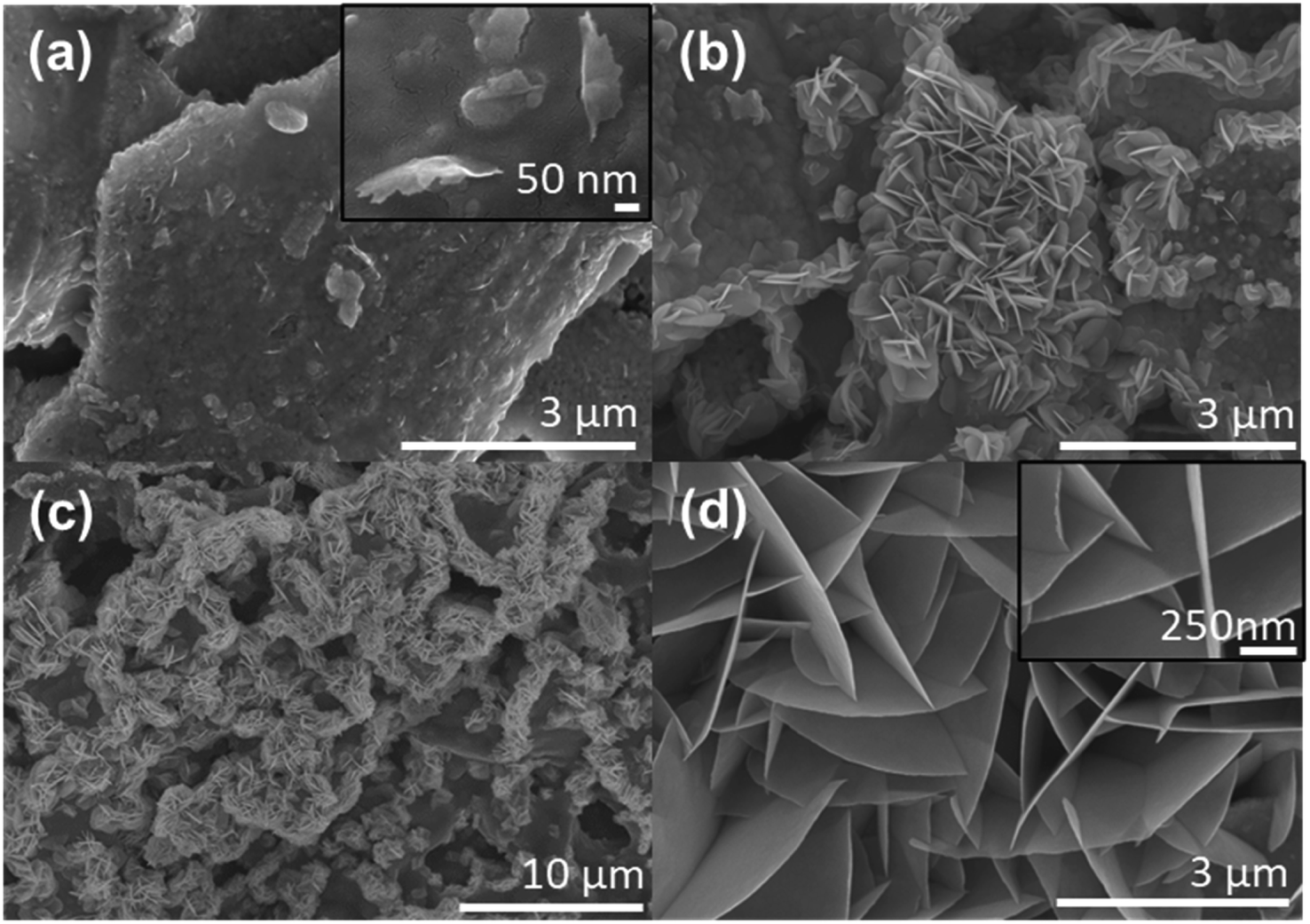 | ||
| Fig. 1 SEM micrographs. (a) BiOCl nanosheets outbreaks and heterojunction formation after 150 °C annealing. The inset shows an intimate contact between both structures. (b) BiOCl nanosheets formation initiated after 225 °C annealing. (c) Fully grown BiOCl nanosheets after 300 °C annealing. (d) Micrograph of the dense networks of BiOCl nanosheets annealed at 300 °C. The inset is a high-resolution micrograph used for thickness determination. | ||
To fully assess the crystalline structure of the nanosheets, X-ray diffraction (XRD) and Raman micro-spectroscopy measurements of the screen-printed photocatalytic cell after annealing at 300 °C are presented in Fig. 2. XRD results in Fig. 2(a) clearly show the presence of sharp and intense peaks originating from three different crystalline structures. The most intense phase belongs to the tetragonal group P4/nmm and matches the BiOCl crystalline structure (ICDD card 01-083-7690).32–34 This spectrum also confirms that the nanosheets do not grow following a preferential facet and thus BiOCl nanosheets are randomly oriented all-over the surface of the film. The two other crystalline phases belong to BFO and Bi2O3. The BFO appears in a rhombohedral phase with a space group R3c (ICDD card 01-086-1518), while the Bi2O3 is an impurity state assigned to tetragonal group P![[4 with combining macron]](https://www.rsc.org/images/entities/char_0034_0304.gif) 21c (ICDD card 00-027-0050).35,36 This Bi2O3 is a common secondary phase that appears during BFO synthesis due to the phase formation's kinetics and is also known to possess photocatalytic properties.37,38 In Fig. 2(b) Raman micro-spectroscopy of the screen-printed cells after annealing confirms the presence of both BFO and BiOCl crystalline structures. From BFO spectrum, three main characteristic peaks can be seen at 73, 142 and 167 cm−1 and correspond to Eg, Eg and A1 modes respectively.39 All these modes are attributed to the displacement of Bi atoms cause by their lone pairs of 6s2 electrons along the z direction.40 The other peaks at 56, 140 and 197 cm−1 are indicative of BiOCl crystallization.34 The first peak corresponds to A1 external Bi–Cl stretching mode, while the second and third peaks are respectively A1 and Eg internal Bi–Cl stretching mode.20,26 In the BiOCl spectrum, some residual contribution from the BFO powders underneath can still be observed at 73 and 167 cm−1. The low-concentration Bi2O3 phase is not detected in the Raman signal.
21c (ICDD card 00-027-0050).35,36 This Bi2O3 is a common secondary phase that appears during BFO synthesis due to the phase formation's kinetics and is also known to possess photocatalytic properties.37,38 In Fig. 2(b) Raman micro-spectroscopy of the screen-printed cells after annealing confirms the presence of both BFO and BiOCl crystalline structures. From BFO spectrum, three main characteristic peaks can be seen at 73, 142 and 167 cm−1 and correspond to Eg, Eg and A1 modes respectively.39 All these modes are attributed to the displacement of Bi atoms cause by their lone pairs of 6s2 electrons along the z direction.40 The other peaks at 56, 140 and 197 cm−1 are indicative of BiOCl crystallization.34 The first peak corresponds to A1 external Bi–Cl stretching mode, while the second and third peaks are respectively A1 and Eg internal Bi–Cl stretching mode.20,26 In the BiOCl spectrum, some residual contribution from the BFO powders underneath can still be observed at 73 and 167 cm−1. The low-concentration Bi2O3 phase is not detected in the Raman signal.
 | ||
| Fig. 2 (a) XRD and (b) Raman spectra of the photocatalytic material after thermal annealing. | ||
In addition, Transmission Electronic Microscopy (TEM) can also be useful to appraise the crystalline structure of the nanosheets. In Fig. 3(a), the high-resolution TEM micrograph shows nanosheets with multiple sets of lattice fringes depending on their orientation. The left and right fringes indicated by green lines possess a d-spacing of 0.728 nm corresponding to the (001) atomic planes of BiOCl. The other fringes close to the center have a smaller d-spacing of 0.343 nm corresponding to (101) atomic planes. TEM micrograph of a typical individual BiOCl nanosheet and the selected area electron diffraction (SAED) pattern are presented in Fig. 3(d) and (e), respectively. The calculated interplanar d-spacing is equal to 0.365 nm and can be attributed to the (002) atomic plane. These results are consistent with the previous XRD measurements. This layered development is typical from BiOCl structures.41 Fig. 3(b) and (c) show EDX measurements of the areas highlighted in Fig. 3(a) to survey their elemental compositions. Both spectra suggest the presence of chlorine, bismuth, oxygen and validate the crystalline structure of the nanosheets. Copper and carbon signals stem respectively from the grid and mesh used for observation of the sample. Presence of iron is also detected in both spectra. It suggests that iron inclusion takes place while chlorine evaporates and reacts with BFO particles to create BiOCl nanosheets. Uniform distribution of these iron atoms is validated in Fig. S3† by EDX elemental mapping using TEM. Element mapping of the bismuth, oxygen and chlorine are also reported in Fig. S3† and confirm a uniform distribution. Transition metal doping and more precisely iron doping of BiOCl nanostructures have been previously reported in the literature for BiOCl.11 Besides trapping and releasing electron–hole pairs, Fe atoms act as impurities. Indeed, impressive band-to-band transition enhancement in BiOCl structures have been measured at sub-bandgap energies.19,20,30,42,43 Thus enhancement of photocatalytic properties can be achieved using Fe-doping compared to pristine BiOCl.20,30,42,43 To assess the impact of iron atoms on the screen-printed photocatalytic cells, Ultraviolet-Visible-Near Infrared spectroscopy (UV-Vis-NIR) absorption spectroscopy measurement is shown in Fig. S4(a).† As explained in the Experimental section, a thin layer of ink is deposited to enable this measurement. It indicates a strong light absorption under 400 nm in the UV region which is attributed to BiOCl. A contribution from iron impurities is also apparent as significant visible light is absorbed between 400 and 800 nm due to defect-mediated band-to-band transition. For comparison, the same measurement is performed on a printed photocatalytic cell before annealing and is shown in Fig. S4(b).† The absorbance promptly decreases below 350 nm which validates that UV absorption is ascribed to BiOCl. Above 350 nm, the BFO absorption spectrum matches with previous reported results.13 Measurements reported in Fig. 2 and 3 confirm that the crystalline structure of the nanosheets on top of the BFO powders matches with BiOCl. Depending on the atmosphere during crystallization, BFO can be either a p or n-type material, while BiOCl is known as a p-type material.18,22,44 In this study, BFO powders are considered as n-type since they are annealed in ambient atmosphere. Therefore, each junction between a BiOCl nanosheet and a BFO particle in Fig. 1 acts as a local p–n heterojunction.
 | ||
| Fig. 3 (a) High-resolution TEM image of BiOCl nanosheets atop of the BFO powder. Green lines indicate lattice fringes, (b and c) Energy-dispersive X-ray spectroscopy (EDX) spectra of respective areas marked in (a). (d) TEM image of a single BiOCl nanosheet and (e) selected area electron diffraction (SAED) pattern of the area marked in (d). | ||
As shown in Fig. 4, thermogravimetric analysis (TGA) measurements can be used to quantify the ink vehicle evaporation during annealing and to determine the residual photocatalyst weight involved during the RhB degradation reactions. In Fig. 4(a), TGA measurement of the ink vehicle shows that most of the weight loss happens under 250 °C. In fact, an impressive 85% mass loss is observed between room temperature and 250 °C. After 250 °C, the mass loss stabilizes and only 10.6% of the initial mass remains at 400 °C. This measurement is consistent with our hypothesis that the formation, size and density of the BiOCl nanosheets depend on the ink vehicle annealing, providing the Cl source for the growth process. Indeed, Fig. 1 shows that the biggest nanosheets are achieved at 300 °C. In ESI Fig. S2,† EDX measurements of the printed cell before annealing confirm the presence of chlorine. In contrast, ESI Fig. S5† shows a reference EDX measurement of the same ink vehicle deposited on silicon and annealed at 300 °C for 1 h. The EDX spectrum in Fig. S5(b)† reveals the presence of chlorine, oxygen, carbon, silicon and platinum. The latest is added on purpose to avoid any charging effects during SEM imaging. All other elements come from the ink vehicle residues left after annealing. The main residual elements are carbon and chlorine, according to the intensity of the characteristic peaks of each element. In Fig. 4(b), TGA measurement of the screen-printed ink is presented. It shows that 43.0% of the initial mass remains at 400 °C. This includes roughly the 33% loading used for the BFO powder in the ink vehicle, combined with the 10.6% leftovers from the ink vehicle measured in Fig. 4(a). Thanks to both TGA measurements, a precise estimation of the amount of photocatalytic material can be obtained. To do so, the weight of the substrate is carefully measured before and after printing. Out of 10 printed photocatalytic cells, the weight of a single printed cell is estimated around 118 mg. As the BFO loading is confirmed to be 33%, some 39 mg of photocatalyst is present on each photocatalytic cell. Compared to similar studies reporting BiOCl/BFO heterojunctions for photocatalytic degradation of RhB, the amount of BiOCl/BFO photocatalyst is reduced by 22%.27 In this work, the authors reported the fabrication of BiOCl/BFO heterojunctions following a chemical acid etching of BFO powders. A 43% degradation of the RhB solution was performed in 75 min under visible light using a colloidal method.
 | ||
| Fig. 4 Thermogravimetric analysis of (a) the ink vehicle degradation over temperature (b) the ink vehicle and BFO powder. | ||
To assess the performances of these screen-printed photocatalytic cells, we illuminate them using a solar simulator (AM 1.5G). A longpass filter (λ ≥ 400 nm) is implemented to remove any contribution from UV light as it can yield some photodegradation of the RhB.45 As we previously established,13 a thin layer of platinum is deposited atop of the annealed screen-printed cells by sputtering to enhance their photocatalytic properties. Adding this thin metallic layer is known to serve as an electron sink by acting as an efficient Schottky barrier.7,25 Post-printing sputtering deposition of this thin layer has the advantage of being straightforward compared to more conventional photocatalyst materials decorated with metallic nanoparticles, which often requires complex processing steps and additional chemicals.46 Compared with sputtered films, nanoparticles tend to agglomerate into clusters to disrupt the photocatalytic reaction.47 Nevertheless, the thickness of the platinum film must be carefully optimized to avoid light absorption and decrease of photocatalytic properties. In fact, previous studies established that a 13 nm thick platinum coating deposited by sputtering yields only 50% transmission from 400 to 800 nm.48 In Fig. 5(a), 2 to 12 nm thick platinum layers are sputtered atop of the screen-printed photocatalytic cells. A remarkable degradation of 92% is achieved for the 2 nm platinum-coated cell after 150 min under illumination at near neutral pH (pH = 6.1). For thicker platinum layers, the degradation steadily decreases from 92% RhB degradation to 90%, 83% and 73% for cells with 4, 8 and 12 nm platinum respectively. This phenomenon can be explained by an increased of light absorption by the platinum layer. Hence, less light reaches the surface of the p–n BiOCl/BFO heterojunctions and the photocatalytic reaction is hindered. In comparison, screen-printed photocatalytic cells without any platinum layer achieve only a 66% RhB degradation. This result proves that a thin film of platinum is an effective way to significantly enhance the photocatalytic reaction's efficiency.
 | ||
| Fig. 5 (a) Photocatalytic degradation of RhB for different thicknesses of platinum layers. (b) Linear curves used to determine the first-order kinetics of RhB degradation over time. The inset shows the values of the fitted curves' slopes (degradation rate). | ||
As a control experiment, no measurable absorption–desorption reaction is recorded under dark conditions for all our photocatalytic experiments. Also, only 14% degradation can be achieved with over 150 min in Fig. S6(b),† despite the presence of both platinum layer and H2O2. Compared with previous papers exhibiting up to 93% of RhB degradation under dark in 30 min, we conclude that the degradation in Fig. S6(b)† can be considered negligible.15,26,49,50 Two conclusions can be drawn from this experiment. First, the photocatalytic degradation reactions are partially triggered by the light beam used to continuously measure absorption from the solution. Secondly, the degradation reactions of RhB necessitate light from the solar simulator to take place and the RhB degradation is not only triggered by combination of both platinum and H2O2. Therefore, RhB degradation takes place because of the photo-generated charge carriers in the catalyst, which in-turn triggers the chemical reactions between both H2O2 and platinum.13 Degradation curves of RhB are fitted in Fig. 5(b) and display a typical Langmuir–Hinshelwood behavior.26,49 R-square values higher than 0.99% are obtained for all degradation curves using the pseudo-first-order kinetic equation: −ln(C/Co) = kappt, where C and Co are live and initial concentrations of RhB, kapp is the apparent first-order kinetics model (min−1) and t is the time.50 The kapp values thus obtained are summarized in the inset of Fig. 5(b). A maximum of 0.00905 min−1 is reached for the 2 nm platinum coated cells, while a minimum of 0.00396 min−1 is calculated for the reference cell without platinum. The photocatalytic cells with 4, 8 and 12 nm platinum layers display respectively kapp values of 0.00865, 0.00661 and 0.00467 min−1. The kapp calculated values confirms that 2 nm platinum coated cell possesses a superior photodegradation reaction compared o the others screen-printed photocatalytic cells.
To account for the RhB degradation over time, absorption spectra taken each 20 min are shown in Fig. 6(a). At t = 0, the maximum peak intensity of RhB is found at 553 nm and decreases promptly when the light is turned on. Low RhB concentration of a solution in the mg L−1 range is known to be proportional to the absorbance.51 Therefore, the decrease in absorbance observed in Fig. 6(a) indicates that photocatalytic reactions take place. Thanks to our colloidal free methodology, live monitoring of RhB degradation is achieved and allows a precise tracking of the degradation processes. Two different degradation mechanisms either the cycloreversion and the de-ethylation are involved.52 The former involves the cleavage of the whole chromophore structure and takes place in the bulk solution, while the latest leads to ethyl groups removal in a stepwise manner.52 De-ethylation happens when the RhB molecules are adsorbed on the catalyst surface.52 In that case, degradation reactions create by-products like N,N,N′-triethyl-rhodamine or N,N′-diethyl-rhodamine with absorption peaks respectively located at 539 and 522 nm.53 In Fig. 6(b), all the screen-printed cells exhibit a significant blue shift. For all the platinum-coated cells, a clear blue shift from 553 to 535-531 nm is observed after 30 min under illumination. This blue shift indicates that de-ethylation is the main degradation process and can be explained by the action of active oxygen species on the N-ethyl group.54 In contrast, screen-printed photocatalytic cells without platinum exhibits a much smaller blue shift starting only after 60 min under irradiation. Maximum peak position moves from 553 to 546 nm. For all the screen-printed cells, this suggests that chromophore cleavage tends to be the dominant degradation mechanism at first, then de-ethylation becomes the most influent degradation mechanism.
 | ||
| Fig. 6 Evolution of the RhB spectra absorption during the photocatalytic degradation by the screen-printed photocatalytic cell coated with 2 nm of platinum. (a) Spectral evolution under illumination. (b) Maximum absorption peak position and its evolution over time. | ||
Conclusions
In this study, we report a colloidal-free synthesis using screen printing as a simple and effective deposition method to produce highly efficient photocatalysis cells. Thanks to chemical reaction between the ink vehicle and the BFO powders during annealing, a dense network of interconnected BiOCl nanosheets is forming atop the BFO particle slurry to create local p–n BiOCl/BFO heterojunctions. Moreover, TEM measurements confirm the presence of iron impurities inside the BiOCl lattice. This phenomenon favours visible light absorption using impurities to trap and release photo-generated charges. These BiOCl sheet-like structures boast impressive aspect ratios with a thickness of 10 ± 2 nm and several microns in length. These photocatalytic cells yield an impressive RhB degradation of 92% in 150 min under visible light, using a thin platinum layer of 2 nm is sputtered on the screen-printed cells to serve as an electron sink. This colloidal free configuration also enables an automated and live tracking of the RhB degradation by recording absorption spectra every 30 s. Compared to BiOCl nano-catalysts usually made by hydrothermal methods, our acid-free approach drastically reduces the synthesis time and can be easily transferred to industry for large-scale manufacturing. We hope this methodology will attract more attention as it solves two of the actual limits of photocatalysis which are the needs for UV sources and for catalyst collection and recovery protocols.Conflicts of interest
There are no conflicts to declare.Acknowledgements
The authors would like to thank both Victor Brial and Michael Dubois for their expertise with thermogravimetric measurements and Alain Picard for his help with the absorbance acquisition setup. The authors also thank Jean-Phillipe Masse for his fruitful discussions regarding the TEM measurements and Mohammad Saadati for his expertise in SEM/EDX measurements. The authors are grateful for the support of Henkel company by providing the ink vehicle used for this study. S. G. C acknowledges the NSERC-Discovery and Canada Research Chair programs for their financial support.References
- J. Rockstrom, W. Steffen, K. Noone, A. Persson, F. S. Chapin 3rd, E. F. Lambin, T. M. Lenton, M. Scheffer, C. Folke, H. J. Schellnhuber, B. Nykvist, C. A. de Wit, T. Hughes, S. van der Leeuw, H. Rodhe, S. Sorlin, P. K. Snyder, R. Costanza, U. Svedin, M. Falkenmark, L. Karlberg, R. W. Corell, V. J. Fabry, J. Hansen, B. Walker, D. Liverman, K. Richardson, P. Crutzen and J. A. Foley, Nature, 2009, 461, 472–475 CrossRef PubMed.
- L. Persson, B. M. Carney Almroth, C. D. Collins, S. Cornell, C. A. de Wit, M. L. Diamond, P. Fantke, M. Hassellov, M. MacLeod, M. W. Ryberg, P. Sogaard Jorgensen, P. Villarrubia-Gomez, Z. Wang and M. Z. Hauschild, Environ. Sci. Technol., 2022, 56, 1510–1521 CrossRef PubMed.
- K. Kabra, R. Chaudhary and R. L. Sawhney, Ind. Eng. Chem. Res., 2004, 43, 7683–7696 CrossRef CAS.
- F. Fresno, R. Portela, S. Suárez and J. M. Coronado, J. Mater. Chem. A, 2014, 2, 2863–2884 RSC.
- W. Zhou, N. Umezawa, R. Ma, N. Sakai, Y. Ebina, K. Sano, M. Liu, Y. Ishida, T. Aida and T. Sasaki, Chem. Mater., 2018, 30, 6449–6457 CrossRef CAS.
- M. B. Bouzourâa, Y. Battie, S. Dalmasso, M. A. Zaïbi, M. Oueslati and A. E. Naciri, Superlattices Microstruct., 2017, 104, 24–36 CrossRef.
- S. M. Sze, Semiconductor devices: physics and technology, John Wiley & sons, 2008 Search PubMed.
- F. Yang, X. Chu, J. Sun, Y. Zhang, Z. Li, H. Liu, L. Bai, Y. Qu and L. Jing, Chin. Chem. Lett., 2020, 31, 2784–2788 CrossRef CAS.
- H. Wang, W. Liu, X. He, P. Zhang, X. Zhang and Y. Xie, J. Am. Chem. Soc., 2020, 142, 14007–14022 CrossRef CAS PubMed.
- J. J. Rueda-Marquez, I. Levchuk, P. Fernández Ibañez and M. Sillanpää, J. Clean. Prod., 2020, 258, 120694 CrossRef CAS.
- X. Wei, M. U. Akbar, A. Raza and G. Li, Nanoscale Adv., 2021, 3, 3353–3372 RSC.
- A. Haruna, I. Abdulkadir and S. O. Idris, Heliyon, 2020, 6, e03237 CrossRef CAS PubMed.
- P. Fourmont, R. Nechache and S. G. Cloutier, ACS Appl. Nano Mater., 2021, 4, 12261–12269 CrossRef CAS.
- A. Dandapat, H. Gnayem and Y. Sasson, Chem. Commun., 2016, 52, 2161–2164 RSC.
- J. Xiong, G. Cheng, G. Li, F. Qin and R. Chen, RSC Adv., 2011, 8, 1542–1553 RSC.
- A. Rajaee, S. Wang, L. Zhao and Y. Liu, J. Phys. Conf. Ser., 2019, 1305, 012046 CrossRef CAS.
- H. Ijaz, R. Zia, A. Taj, F. Jameel, F. K. Butt, T. Asim, N. Jameel, W. Abbas, M. Iqbal, S. Z. Bajwa and W. S. Khan, Appl. Nanosci., 2020, 10, 3569–3576 CrossRef CAS.
- Y. Wu, B. Yuan, M. Li, W. H. Zhang, Y. Liu and C. Li, Chem. Sci., 2015, 6, 1873–1878 RSC.
- C. Huang, J. Hu, S. Cong, Z. Zhao and X. Qiu, Appl. Catal., B, 2015, 174–175, 105–112 CrossRef CAS.
- M. Z. Shahid, R. Mehmood, M. Athar, J. Hussain, Y. Wei and A. Khaliq, ACS Appl. Nano Mater., 2020, 4, 746–758 CrossRef.
- S. Das, P. Fourmont, D. Benetti, S. G. Cloutier, R. Nechache, Z. M. Wang and F. Rosei, J. Chem. Phys., 2020, 153, 084705 CrossRef PubMed.
- Z. He, Y. Shi, C. Gao, L. Wen, J. Chen and S. Song, J. Phys. Chem. C, 2013, 118, 389–398 CrossRef.
- J. A. Nelson, The physics of solar cells, World Scientific Publishing Company, 2003 Search PubMed.
- M. Long, W. Cai, J. Cai, B. Zhou, X. Chai and Y. Wu, J. Phys. Chem. B, 2006, 110, 20211–20216 CrossRef CAS PubMed.
- H. Yang, Mater. Res. Bull., 2021, 142, 111406 CrossRef CAS.
- Y. Yan, H. Yang, Z. Yi and T. Xian, Catalysts, 2019, 9, 795 CrossRef CAS.
- J. Shang, H. Chen, T. Chen, X. Wang, G. Feng, M. Zhu, Y. Yang and X. Jia, Appl. Phys. A, 2019, 125 Search PubMed.
- X. Yang, S. Sun, J. Cui, M. Yang, Y. Luo and S. Liang, Cryst. Growth Des., 2021, 21, 6576–6618 CrossRef CAS.
- P. G. Jamkhande, N. W. Ghule, A. H. Bamer and M. G. Kalaskar, J. Drug Deliv. Sci. Technol., 2019, 53, 101174 CrossRef CAS.
- J. Xia, L. Xu, J. Zhang, S. Yin, H. Li, H. Xu and J. Di, CrystEngComm, 2013, 15, 10132–10141 RSC.
- F. Dong, T. Xiong, Y. Sun, Y. Zhang and Y. Zhou, Chem. Commun., 2015, 51, 8249–8252 RSC.
- K. G. Keramidas, G. P. Voutsas and P. I. Rentzeperis, Z. Kristallogr. - Cryst. Mater., 1993, 205, 35–40 CrossRef CAS.
- A. Biswas, R. Das, C. Dey, R. Banerjee and P. Poddar, Cryst. Growth Des., 2013, 14, 236–239 CrossRef.
- Y. Xu, S. Xu, S. Wang, Y. Zhang and G. Li, Dalton Trans., 2014, 43, 479–485 RSC.
- C. Ponzoni, R. Rosa, M. Cannio, V. Buscaglia, E. Finocchio, P. Nanni and C. Leonelli, J. Alloys Compd., 2013, 558, 150–159 CrossRef CAS.
- C. Ponraj, G. Vinitha and J. Daniel, Int. J. Green Energy, 2019, 17, 71–83 CrossRef.
- H. Weidong, Q. Wei, W. Xiaohong, D. Xianbo, C. Long and J. Zhaohua, Thin Solid Films, 2007, 515, 5362–5365 CrossRef.
- M. S. Bernardo, T. Jardiel, M. Peiteado, A. C. Caballero and M. Villegas, J. Eur. Ceram. Soc., 2011, 31, 3047–3053 CrossRef CAS.
- J. Wang, L. Luo, C. Han, R. Yun, X. Tang, Y. Zhu, Z. Nie, W. Zhao and Z. Feng, Materials, 2019, 12, 1444 CrossRef CAS PubMed.
- S. Chauhan, M. Kumar, S. Chhoker and S. C. Katyal, J. Alloys Compd., 2016, 666, 454–467 CrossRef CAS.
- Y. Zhang, X. Xu, Y. Xing, H. Wang, H. Fu, X. Lin and J. Wang, Adv. Mater. Interfaces, 2015, 2, 1500194 CrossRef.
- F. Tian, G. Li, H. Zhao, F. Chen, M. Li, Y. Liu and R. Chen, J. Catal., 2019, 370, 265–273 CrossRef CAS.
- Z. Shen, F. Li, J. Lu, Z. Wang, R. Li, X. Zhang, C. Zhang, Y. Wang, Y. Wang, Z. Lv, J. Liu and C. Fan, J. Colloid Interface Sci., 2021, 584, 174–181 CrossRef CAS PubMed.
- T. Rojac, A. Bencan, B. Malic, G. Tutuncu, J. L. Jones, J. E. Daniels, D. Damjanovic and D. J. Green, J. Am. Ceram. Soc., 2014, 97, 1993–2011 CrossRef CAS.
- W. Wang, N. Li, Y. Chi, Y. Li, W. Yan, X. Li and C. Shao, Ceram. Int., 2013, 39, 3511–3518 CrossRef CAS.
- H. Zhang, G. Liu, L. Shi and J. Ye, Adv. Energy Mater., 2018, 8, 1701343 CrossRef.
- F. Niu, D. Chen, L. Qin, T. Gao, N. Zhang, S. Wang, Z. Chen, J. Wang, X. Sun and Y. Huang, Sol. Energy Mater. Sol. Cells, 2015, 143, 386–396 CrossRef CAS.
- H. G. Tompkins, S. Tasic, J. Baker and D. Convey, Surf. Interface Anal., 2000, 29, 179–187 CrossRef CAS.
- J. Sun, Y. Cai, H. Xu, Z. Zou, M. Hu, X. Jin, L. Sun, D. Li and D. Xia, Chem. Phys. Lett., 2018, 711, 207–212 CrossRef CAS.
- Y.-y. Gu, L. Zhao, M.-y. Yang, Y.-q. Xiong, Z. Wu, M.-j. Zhou and J. Yan, J. Cent. South Univ., 2017, 24, 754–765 CrossRef CAS.
- H. B. Kim, M. Hayashi, K. Nakatani, N. Kitamura, K. Sasaki, J. Hotta and H. Masuhara, Anal. Chem., 1996, 68, 409–414 CrossRef CAS PubMed.
- M. Pica, S. Calzuola, A. Donnadio, P. Gentili, M. Nocchetti and M. Casciola, Catalysts, 2018, 9, 3 CrossRef.
- T. Watanabe, T. Takizawa and K. Honda, J. Phys. Chem., 2002, 81, 1845–1851 CrossRef.
- Y. Hu, D. Li, H. Wang, G. Zeng, X. Li and Y. Shao, J. Mol. Catal. A: Chem., 2015, 408, 172–178 CrossRef CAS.
Footnote |
| † Electronic supplementary information (ESI) available. See https://doi.org/10.1039/d2ra03308a |
| This journal is © The Royal Society of Chemistry 2022 |