
 Open Access Article
 This Open Access Article is licensed under a Creative Commons Attribution-Non Commercial 3.0 Unported Licence
Coatings of hydroxyapatite–bioactive glass microparticles for adhesion to biological tissues†
Estelle Palierse a,
Maïlie Roquartab,
Sophie Norveza and
Laurent Corté*ab
a,
Maïlie Roquartab,
Sophie Norveza and
Laurent Corté*ab
aMolecular, Macromolecular Chemistry, and Materials, ESPCI Paris, CNRS, PSL University, 75005 Paris, France. E-mail: laurent.corte@minesparis.psl.eu
bCentre des Matériaux, MINES Paris, CNRS, PSL University, 91003 Evry, France
First published on 22nd July 2022
Abstract
Adsorption of particles across interfaces has been proposed as a way to create adhesion between hydrogels and biological tissues. Here, we explore how this particle bridging approach can be applied to attach a soft polymer substrate to biological tissues, using bioresorbable and nanostructured hydroxyapatite–bioactive glass microparticles. For this, microparticles of aggregated flower-like hydroxyapatite and bioactive glass (HA–BG) were synthesized via a bioinspired route. A deposition technique using suspension spreading was developed to tune the coverage of HA–BG coatings at the surface of weakly cross-linked poly(beta-thioester) films. By varying the concentration of the deposited suspensions, we produced coatings having surface coverages ranging from 4% to 100% and coating densities ranging from 0.02 to 1.0 mg cm−2. The progressive dissolution of these coatings within 21 days in phosphate-buffered saline was followed by SEM. Ex vivo peeling experiments on pig liver capsules demonstrated that HA–BG coatings produce an up-to-two-fold increase in adhesion energy (9.8 ± 1.5 J m−2) as compared to the uncoated film (4.6 ± 0.8 J m−2). Adhesion energy was found to increase with increasing coating density until a maximum at 0.2 mg cm−2, well below full surface coverage, and then it decreased for larger coating densities. Using microscopy observations during and after peeling, we show that this maximum in adhesion corresponds to the appearance of particle stacks, which are easily separated and transferred onto the tissue. Such bioresorbable HA–BG coatings give the possibility of combining particle bridging with the storage and release of active compounds, therefore offering opportunities to design functional bioadhesive surfaces.
1. Introduction
With the blossoming of soft polymers and hydrogels for implants and biofabrication processes, there is great interest in improving the adhesion of such materials to biological tissues. Nevertheless, the surface wetting by biological fluids and the formulation constraints imposed by biocompatibility requirements make it challenging to design soft macromolecular networks that adhere to the surface of biological tissues. Great research efforts have been invested to improve tissue–hydrogel adhesion, in particular by inserting moieties into the polymeric network that can bind covalently1–3 or supramolecularly1,4 with tissue macromolecules. Particle bridging is another strategy where particles are used as connectors between hydrogels and tissues.5 In this approach, particles are placed at the interface and the adsorption of macromolecular chains from both sides onto the surface of the particles creates an adhesive contact by non-covalent interactions in less than five minutes. Even though the adhesion strength produced by particle bridging is generally lower than the one obtained by covalent binding, this method offers several interesting features, and can sustain non-negligible levels of deformation.6–8 Unlike for polymer glues, the use of particles preserves the permeability needed for interfacial exchanges and delivery of active substances. It also provides an easy way to add other functionalities, such as contrast enhancement for imaging,8 hemostasis,6,7 antioxidant,9 or antibacterial10 effects. In addition, these performances present the opportunity of temporary immobilization of devices, which can be retrieved without the use of additives to break covalent binding or UV irradiation to reverse supramolecular interactions.11 Coatings of particles may also provide a valuable complement to stronger but more invasive adhesive strategies to enhance the local bio-integration of implants and to design multifunctional surgical adhesives.Adhesion by particle bridging is applicable to a large variety of particles, tissues and hydrogels. The in vivo applicability of the approach was demonstrated on small animal, using iron oxide nanoparticles to close wounds, or silica nanoparticles to fasten hydrogel membranes on the surface of heart and liver.12 Other nanoparticles such as zinc and titanium oxides were also reported for wound closure in mice.13 We recently showed the efficiency of procoagulant silica nanoparticles to enhance the adhesion of PEG hydrogel membranes in vivo in presence of blood through the formation of an interfacial blood clot.7 Even though silica nanoparticles are often used in particle bridging strategies,8 their biocompatibility is arguable, and the cytotoxicity of these particles has been shown to depend on their size and specific surface area.14–16 There is thus an interest for biocompatible and bioresorbable particles to design bio-adhesive coatings. In this context, an enhancement of the adhesion of PEG hydrogels on pig liver7 was achieved using mesoporous silica particles that degrade rapidly in physiological medium.17 A recent study also emphasized the potential of biodegradable porous silicon nanoparticles for wound closure.18
Bioactive glass and calcium phosphate particles are two promising biocompatible and bioresorbable candidates. On the one hand, silicate-based bioactive glass (BG) is well known in the field of bone regeneration.19 BG consists in a silica network containing calcium and phosphate oxides. In contact with biological fluids, BG can produce carbonated hydroxyapatite and this newly formed bone-like material chemically stimulates bone regeneration. Interaction between BG particles and soft collagen tissues was also reported in vitro,20 and the potential of BG particles for soft tissue regeneration was reviewed several times.21–23 The use of BG particles for adhesion by particle bridging was reported in recent papers,6,24 where suspensions of bioactive glass in combination with ceria particles demonstrated adhesive properties and permitted to glue skin tissues, ex vivo and in vivo.
On the other hand, calcium phosphate ceramics are frequently used as bone regeneration material.25 In particular, hydroxyapatite (HA), which is the major inorganic component of human bones and teeth, can be synthesized to be biocompatible.26–28 While crystalline and stoichiometric forms of HA induce an inflammatory and fibrotic response in vivo,29 biomimetic HA mimicking the highly substituted, carbonated and poorly crystalline form of bone hydroxyapatite is little pro-inflammatory.30 The adsorption of molecules of the extra-cellular matrix on hydroxyapatite was previously reported,31,32 making HA a potential candidate as bridging connector. It has already been shown by Okada et al.33 that suspensions or assembled plates of HA nanoparticles were able to glue different mouse tissues ex vivo. Another calcium phosphate based material, the octacalcium phosphate block, was recently shown to adhere strongly ex vivo to mouse dermal tissues.34
In addition to their potential for tissue adhesion, both HA and BG particles may be interesting to deliver local therapeutic treatments. The ability of the HA lattice to accept ionic substitutions provides a way to insert metallic ions like silver, copper or zinc, which have antibacterial or anti-inflammatory effects.35–37 Similar properties may be conferred to BG particles by tailoring the composition of the material.38 In this case, the drug would be released at the same rate than the dissolution of the BG particles, and a sustained release effect would be expected. Mixing HA and BG would combine advantages of both particles. Such blends have been reported, in particular in the field of bone regeneration, often synthesized via a sol–gel route.39–42 In the present work, we explore the use of mixed HA–BG particles as bridging connectors. For that, we adapt a bioinspired synthesis of HA described by El Fiqi et al.,28 in order to achieve a partial mineralization of BG in HA and create an intimate mixture of both BG and HA particles.
Using these HA–BG particles, our aim is to investigate the relationship between the surface density of particle coatings and the adhesion produced by particle bridging. Indeed, the adhesion by particle bridging is strongly dependent on the way particles are distributed and aggregated at the interface,17,43 but little is understood so far on that topic. In most particle-bridging studies, particles have been deposited as suspensions of nanoparticles or aggregates. Brush spreading of powders was also reported,7,12 but this method is not convenient to control and adjust the coating properties because saturation of the surface is always reached. Here, we propose to adjust the surface density of HA–BG coatings by spreading and drying liquid suspensions of microscopic aggregates at the surface of soft cross-linked polymer films.
In the proposed approach, poly(beta-thioester) (PBT) films were used for their low cytotoxicity44 and their degradability in physiological conditions.44,45 We measured the adhesion created by particle bridging between these HA–BG coated films and the capsule of porcine liver, which is the outer surface of the liver composed of a collagen rich membrane. Porcine liver was chosen as it is commonly used to assess the properties of surgical adhesives.2,3,7,8 It is a particularly challenging substrate and the reported adhesion values are usually substantially lower than the ones obtained on other organs such as the heart or the small intestine.2,3 By combining microscopic observations to peeling experiments, we intend to determine how the adhesion energy resulting from particle bridging depends on the density and microstructure of the HA–BG coatings.
2. Experimental section
2.1. Chemicals
Ethanol (≥99.8%), poly(ethylene glycol) (PEG, Mn = 8000 g mol−1); poly(ethylene glycol) diacrylate (PEG-DA, Mn = 700 g mol−1); 1,6-hexanedithiol (HT); triethylamine; tetrahydrofuran; toluene; pentaerythritol tetrakis (3-mercaptopropionate) (QT); Irgacure 2959; phosphate-buffered saline without calcium and magnesium (PBS) were purchased from Sigma-Aldrich. Thioglycerol (≥98%, MT) was purchased from TCI. Tetraethoxysilane (TEOS, 98%) and calcium nitrate tetrahydrate (99.0–103%) were purchased from Alfa Aesar. For preparing the Simulated Body Fluid (SBF): sodium chloride, sodium hydrogenocarbonate, dipotassium hydrogenophosphate trihydrate and calcium chloride dihydrate were purchased from Sigma-Aldrich; magnesium chloride hexahydrate from Acros Organics; sodium disulfate, potassium chloride and tris(hydroxymethylaminomethane) from Alfa Aesar. All chemicals were used as purchased.2.2. Ex vivo liver tissues
Entire porcine livers were purchased from a local butcher (“Aux fleurons de la viande”, Paris, France). Livers were transported in a cooler, stored at 4 °C, and used during the day following their purchase (18–42 h after harvesting). Tissues were not stored in the freezer at any time as this is known to alter their integrity.46 These acceptable storage times were determined from a previous study comparing freshly explanted and butcher livers.47 With the studied uncoated PBT films, a preliminary study with two livers showed a decrease in adhesion energy from 4 ± 1 J m−2 to 2.9 ± 0.4 J m−2 for storage times exceeding 48 h after harvesting.2.3. Synthesis and characterization of hydroxyapatite (HA) and hydroxyapatite–bioactive glass (HA–BG) particles
Mixed hydroxyapatite–bioactive glass microparticles were synthesized using a protocol modified from El Fiqi et al.28 Briefly, a bioactive glass precursor was obtained from a sol–gel method before a mineralization step in SBF. As a control, pure hydroxyapatite microparticles were also synthesized following the exact same protocol as El Fiqi et al.28![[thin space (1/6-em)]](https://www.rsc.org/images/entities/char_2009.gif) 000 rpm for 10 min, washed 3 times with distilled water and twice with ethanol. After drying overnight at 70 °C, particles were calcinated at 600 °C under atmospheric conditions for 5 h after a ramp of 1 °C min−1 in a Nabertherm apparatus.
000 rpm for 10 min, washed 3 times with distilled water and twice with ethanol. After drying overnight at 70 °C, particles were calcinated at 600 °C under atmospheric conditions for 5 h after a ramp of 1 °C min−1 in a Nabertherm apparatus.For synthesis of HA–BG microparticles, the synthesis of the BG precursor was slightly modified. Ethanol was chosen as the solvent and the sonication step was skipped during the addition of TEOS. After 24 h of reaction at 40 °C, particles were recovered, washed, dried and calcinated following the same protocol as the one for pure HA microparticles.
000 rpm for 10 min, washed 3 times with distilled water and once with ethanol. Particles were dried for 24 h at room temperature under the fume hood.Crystallinity. Phase identification was done using X-ray diffraction (XRD) spectra recorded on a Philips X'pert Modular Powder diffractometer XRD2, equipped with a Bragg Brentano θ–2θ geometry between 10° and 80°, using the Cu K-α wavelength (λ = 1.54 Å).
Microstructure. BG, HA and HA–BG particles were observed with a Quattro ESEM from ThermoFischer Scientific, operating under an accelerating voltage of 10 kV and a beam current of 46 pA. Samples were deposited on a conductive copper/nickel tape and coated with a 5 nm Au layer using a Cressington 108 sputter coater operated at 20 mA for 30 s. For X-ray energy dispersive spectroscopy (EDS) measurements, a voltage of 15 kV was used, with a ThermoFischer detector.
Specific surface area. Nitrogen porosimetry measurements were performed on a Micromeritics TriStar instrument at 77 K, after activating the samples on a VacPrep device (15 h at 150 °C). The specific surface area of all compounds was calculated through the Brunauer, Emmett and Teller (BET) method.
2.4. Fabrication and characterization of cross-linked PBT films
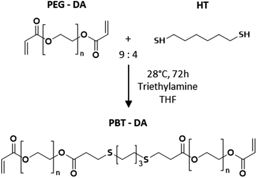 | ||
| Scheme 1 Synthesis route of PBT-DA used to make photo-cross-linked film. | ||
:3 molar ratio mixture of monothiol (thioglycerol, MT) and tetrathiol (pentaerythritol tetrakis (3-mercaptopropionate), QT) and a 9:4 molar ratio for thiol:acrylate functions. PBT-DA (1 eq.), MT (0.56 eq.) and QT (1.69 eq.) were first dissolved in THF (20 wt%). The photoinitiator, Irgacure 2959, was dissolved in ethanol at 0.01 mg per mL. This solution was added to the mixture in 0.01 vol%. Samples for coating and adhesion were obtained by spreading the solution on a paper backing using a metal knife to ensure the proper boundary conditions for elastic peeling. Photo-cross-linking was performed by UV irradiation for 1 min at 365 nm and 1 W cm−2 in a UV CHAMBER™ apparatus. The obtained films were dried in an oven at 80 °C for 10 min to remove traces of THF and were subsequently stored in a closed container at controlled temperature (T = 21 ± 1 °C). For 10 g of solution, 8 × 10 cm2 films having a 1.6 ± 0.1 mm thickness were obtained after drying. 2 mm-thick films with no paper backing were also produced for characterization experiments (2.4.3) and were spread onto the surface of a glass plate previously treated with cerium oxide.Swelling ratio and sol fraction. 1 cm-diameter disks of cross-linked PBT films without backing were dried under vacuum at 60 °C for 3 h to determine their initial dried mass (mD). Then, these pieces were immersed in an excess of ultrapure water (20 °C < T < 22 °C) and weighed to obtain the swollen mass (mS). Equilibrium swelling was reached after about 12 h. After 24 h, the swollen films were re-dried under vacuum at 60 °C overnight to obtain the re-dried mass (mRD). The equilibrium swelling ratio and the soluble fraction were defined as Q = mS/mRD and SF = (1 − mRD/mD), respectively.
Mechanical properties. The mechanical characterization of the PBT films was performed on a tensile test apparatus (All Around, Zwick) equipped with a 10 N load cell. Rectangular stripes were cut from dry films with dimensions 10 mm × 5 mm × 0.5 mm. Samples of dry films were stretched until rupture at a speed of 1 mm s−1 (Fig. S1†). Rheological measurements were performed on a MCR 302 Anton Paar rheometer. A frequency sweep from 0.001 to 100 rad s−1 was assessed at 20 °C and a 1%-shear strain. To determine the Dahlquist criterium and dissipation parameters, loss and storage modulus were taken at 1 Hz.
2.5. Coating deposition and characterization
:50 (vol%) EtOH:H2O mixture. The concentration of particles was varied from 1 to 50 mg mL−1. These particle suspensions were deposited onto the surface of PBT films with 20 and 200 μL micropipettes (Gilson Pipetman), less than 30 s after being homogenized with ultrasounds for 30 s (BRANSONIC® Ultrasonic Cleaner). Two geometries of PBT films were used: 1 × 1 cm2 squares for coating characterization and 8 × 1 cm2 ribbons for adhesion testing. A fixed amount of suspension per unit area of film was deposited and homogeneously spread by sweeping 4–5 times with a spatula during 15–20 s. Drying was performed for 2 h at 20 °C in a desiccator. Table 1 gathers the different conditions used for this study. They are referred to as Vx_Cy, where x is the deposited suspension volume per unit area of the film in μL cm−2, and y the suspension concentration in mg mL−1. In a first series of experiments (Table 1, V10_C20), the adhesion produced by pure HA, BG precursors and HA–BG coatings was investigated. For that, all the coatings were obtained with a deposited volume of 10 μL cm−2 and a coating density of 0.2 mg cm−2. In a second series of experiments (Table 1, V20_C1 to V20_C50), HA–BG coatings with varying coating densities were produced to investigate the relationship between adhesion and coating density. For that, a deposited volume of 20 μL cm−2 was employed. The particle concentration in the suspension was varied from 1 to 50 mg mL−1, which corresponds to coating densities ranging from 0.02 to 1 mg cm−2.
| Coating reference | Deposited suspension volume (μL cm−2) | Suspension concentration (mg mL−1) | Coating density (mg cm−2) | |
|---|---|---|---|---|
| Comparison of HA, BG and HA–BG coatings | V10_C20 | 10 | 20 | 0.2 |
|
||||
| HA–BG coatings | V20_C1 | 20 | 1 | 0.02 |
| V20_C5 | 5 | 0.1 | ||
| V20_C10 | 10 | 0.2 | ||
| V20_C15 | 15 | 0.3 | ||
| V20_C20 | 20 | 0.4 | ||
| V20_C25 | 25 | 0.5 | ||
| V20_C35 | 35 | 0.7 | ||
| V20_C50 | 50 | 1.0 | ||
2.6. Adhesion to biological tissues by ex vivo peeling
3. Results and discussion
3.1. Synthesis and characterization of HA–BG microparticles
In this work, we modified the synthesis protocol described by El Fiqi et al.28 to produce hybrid microparticles of hydroxyapatite–bioactive glass. As a control, we produced pure hydroxyapatite (HA) microparticles using the same protocol as in El Fiqi et al.28 The HA particles were obtained from the mineralization in Simulated Body Fluid, SBF, of precursor nanoparticles made of bioactive glass (BG), as depicted in Fig. 1A. BG nanoparticles having 100 nm diameter were synthesized to achieve a composition of SiO2:CaO (85:25). These nanoparticles were assembled into microscopic aggregates, as shown by SEM in Fig. 2A. After the conversion of BG in HA, nanostructured flower-like microparticles composed of platelets were obtained, as shown in Fig. 2B. The X-ray diffractogram shown in Fig. 2E confirmed the presence of hydroxyapatite when compared with characteristic peaks of hydroxyapatite reference JCPDS 00-009-0432.
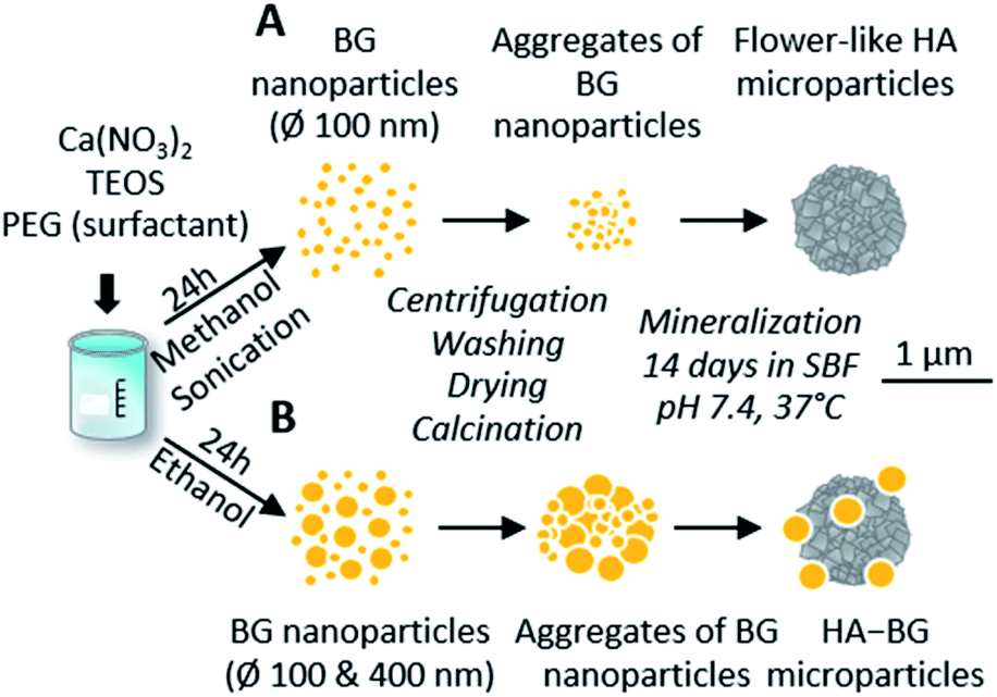 | ||
| Fig. 1 Schematic representation of pure HA and HA–BG formation from bioactive glass nanoparticles via a biomimetic process in SBF. (A) Pure HA flower-like microparticles using the protocol by El Fiqi et al.:28 synthesis of a unique population of BG nanoparticle precursor via sol–gel route in methanol under sonication; aggregation followed by total conversion into flower-like HA during 14 days in SBF in physiological conditions. (B) Mixed HA–BG microparticles using a modified protocol: synthesis of two populations of BG nanoparticle precursor via a sol–gel route in ethanol; aggregation followed by partial conversion into flower-like HA during 14 days in SBF in physiological conditions. | ||
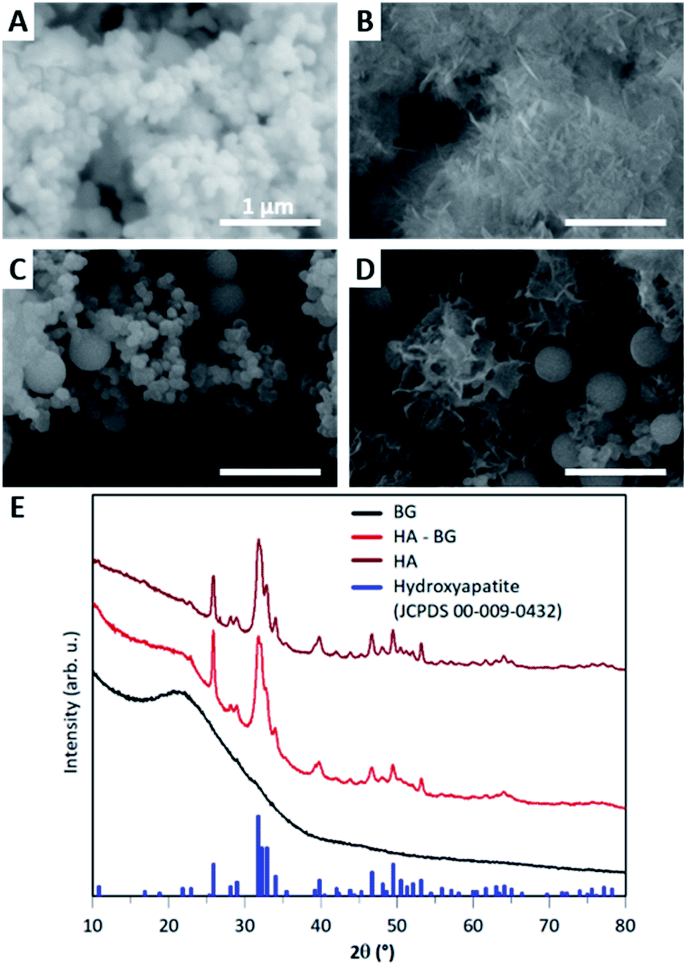 | ||
| Fig. 2 Characterization of HA and HA–BG particles. (A and B) SEM observations of the BG particle precursors (A) and HA flower-like microparticles (B) synthesized using the protocol of El Fiqi et al. (C and D) SEM observations of the BG nanoparticle precursors (C) and the mixed HA–BG microparticles (D) synthesized using our modified protocol. Magnification ×100000. (E) X-ray diffractograms of the BG particle precursors and HA and HA–BG particles. Blue peaks show peak positions of hydroxyapatite reference JCPDS card 00-009-0432. | ||
In order to produce a mixture of BG and HA particles, we modified the synthesis of the BG precursor to obtain a bi-population of small and large BG particles, as illustrated in Fig. 1B. For that, we did not assist the synthesis with sonication to promote early aggregation. Instead of methanol, we used ethanol as it is known to lead to bigger particles.50 With these modifications, we obtained a bi-population of spherical nanoparticles, some with a diameter of 100 nm and others with a diameter of 400 nm, as shown in Fig. 2C. The EDX spectra measured during these SEM observations indicated a composition of 8% of Ca and 30% of Si, which is consistent with the expected Ca/Si ratio of 0.2 for BG (Fig. S3†). The X-ray diffractogram in Fig. 2E obtained with these BG particles showed a single broad peak with a maximum around 2θ = 22° and the absence of sharp diffraction peaks, confirming the amorphous nature of both the small and large BG particles.
The same mineralization step as for pure HA particles was performed within this bi-population of BG nanoparticles. Fig. 2D shows an SEM image of the particles obtained at the end of the 14 days of mineralization in SBF. Two different types of particles can be clearly distinguished: (i) 400 nm diameter spherical particles which are very similar to the ones observed in the initial BG precursor, suggesting that these larger nanoparticles were not converted in the duration of the mineralization; (ii) microscopic flower-like nanostructured particles which result from the mineralization of the small BG nanoparticles. A Ca/P ratio of 2.0 ± 0.3 and a Ca/Si ratio of 1.7 ± 1.1 were calculated from EDX spectra (Fig. S4†). This Ca/P ratio is close to the one of stoichiometric hydroxyapatite (1.67), with a slight excess of calcium that can be related to the remaining presence of BG. Moreover, traces of Mg and Na were detected. Accordingly, the X-ray diffractogram shown in Fig. 2E revealed the coexistence of a large peak around 2θ = 22°, characteristic of amorphous BG, and a series of sharp peaks coinciding with the characteristic peaks of hydroxyapatite reference JCPDS 00-009-0432. These peaks are less sharp that the ones of pure HA, meaning that hydroxyapatite in HA–BG is less crystalline than in HA particles. Both these SEM and X-ray results confirm that this modified protocol led to the formation of HA–BG particles made of microscopic aggregates of spherical BG particles and flower-like HA particles.
N2 sorption experiments were performed to assess the porosity of the bi-population of BG precursor particles and the HA–BG microparticles. For the BG precursor particles, no porosity could be measured within the range of pressure that were used. On the contrary for HA–BG particles, a sorption isotherm curve was obtained (Fig. S5†), associated with a specific surface area (SSA) of 26 m2 g−1. This measurement can be attributed to the textural porosity corresponding to the surface of the flower-like nanostructured HA particles, which is absent in the spherical and dense BG particles.
3.2. HA–BG coatings with tunable density
Coatings of HA–BG particles were achieved by spreading particle suspensions on cross-linked PBT films, as depicted in Fig. 3. These films are very soft elastomers chosen for their appropriate viscoelastic behaviour from an adhesive point of view (Dahlquist criterion G′ < 105 Pa at 1 Hz; dissipation G′′/G′ = 0.41 at 1 Hz at 20 °C). The density of the coatings was adjusted by varying the particle concentration in the suspension (see Table 1 in the Experimental section).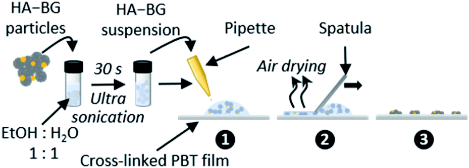 | ||
| Fig. 3 Schematic representation of the deposition protocol of HA–BG particles on (crosslinked) PBT films. | ||
The characteristic morphology of the V20_C10 coating, having a coating density = 0.2 mg cm−2, is shown in more detail in Fig. 4. Apart from a 1.5 mm wide area near the edges where no or few particles are deposited, as depicted in Fig. 4A, the central part of the films is covered by a uniform coating consisting of patterned dark-gray zones and light-gray zones (Fig. 4B & C). EDS analysis confirmed that the dark-gray zones correspond to the bare PBT film while light-gray zones correspond to areas covered with particles (Fig. S6†). Those particles were grouped in clusters embedded in the soft PBT film having their upper part exposed at the surface (Fig. 4D). In these coated areas, observations at high magnification such as the one in Fig. 4E revealed that the micro- and nanostructure of the particles were exposed to air at the surface. Furthermore, the mixture of spherical BG and flower-like HA particles was clearly visible.
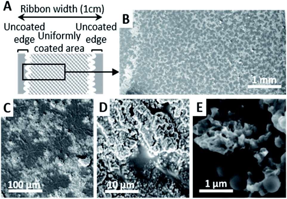 | ||
| Fig. 4 Coating morphology. (A) Schematic representation of the HA–BG coating distribution on a PBT ribbon with uncoated edges resulting from the solvent retraction during drying. (B–E) SEM observations of the dry coating at magnification ×100 (B), ×1000 (C), ×10000 (D) and ×100000 (E). Coating density 0.2 mg cm−2. | ||
Both the uncoated edges and the patterned aspect of the coating can be explained by capillary effects occurring during deposition and air-drying. In particular, these observations are consistent with the coffee-stain effect51–53 and its reverse phenomenon,54 which have been observed after complete evaporation of the solvent when a volatile liquid drop containing small solid particles is deposited on a substrate, as it is the case here.
SEM images of the HA–BG coatings obtained when varying the concentration from 1 to 50 mg mL−1 are shown in Fig. 5 and 6 at low and high magnifications, respectively. For the lowest concentration, V20_C1, scarce clusters of HA–BG particles were randomly distributed on the surface (Fig. 5B and 6B) and most of the surface was similar to the one of the uncoated film (Fig. 5A and 6A). For suspension concentrations ranging from 5 to 35 mg mL−1, namely V20_C5 to C35, a clustering of HA–BG particles similar to the case of V20_C10 was observed. As a result, all the films were covered by a mixed pattern of coated and uncoated areas (Fig. 5C–H). With increasing suspension concentration, the number and extent of the uncoated areas decreased. For V20_C35, the surface was almost saturated with only a few uncoated areas (Fig. 5H). For V20_C50, the surface was entirely covered with HA–BG particles (Fig. 5I).
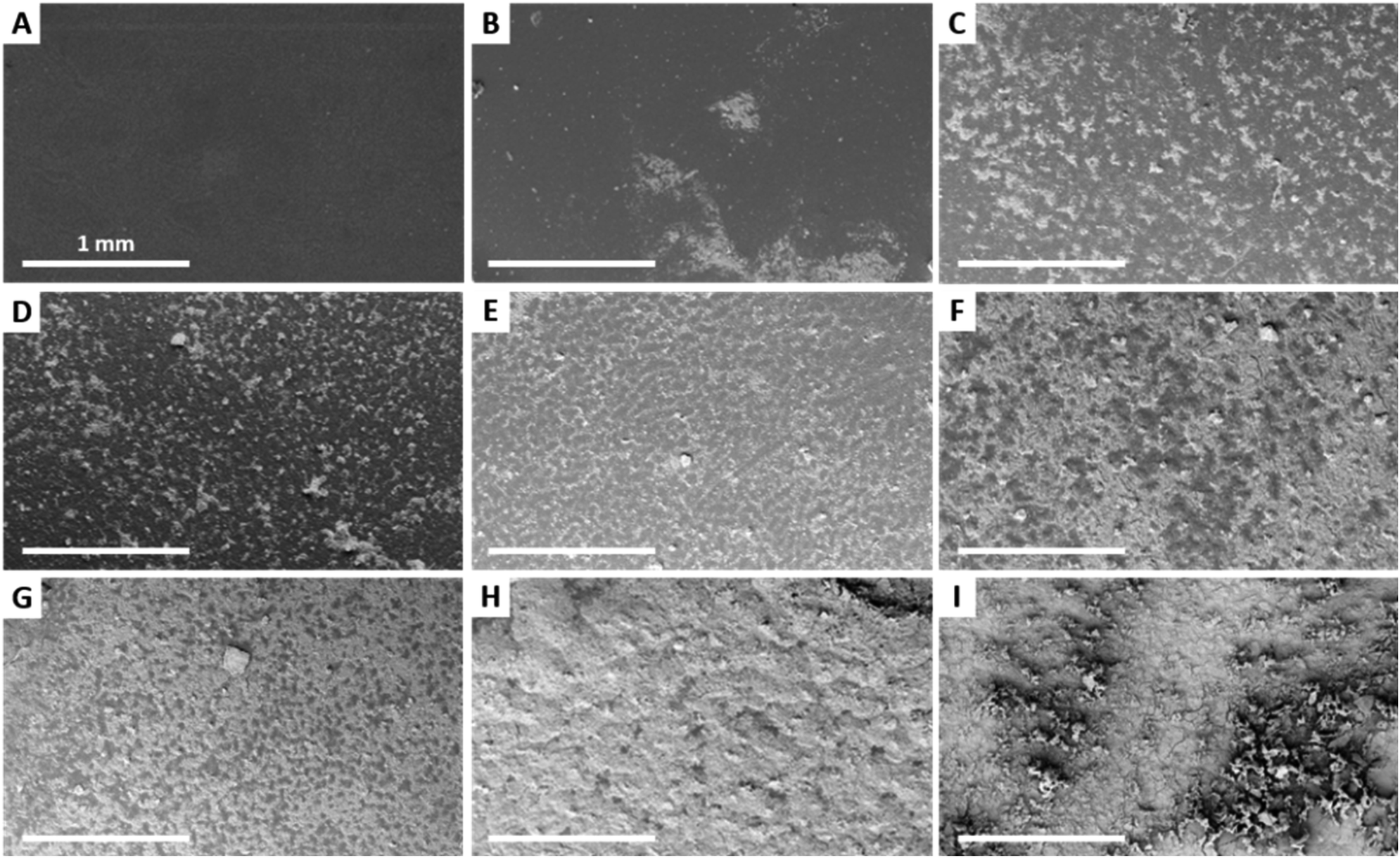 | ||
| Fig. 5 Low (×100) magnification SEM images of uncoated and HA–BG coated films obtained with a fixed deposited suspension volume (20 μL cm−2) and increasing suspension concentrations: (A) uncoated film; (B) 1 mg mL−1; (C) 5 mg mL−1; (D) 10 mg mL−1; (E) 15 mg mL−1; (F) 20 mg mL−1; (G) 25 mg mL−1; (H) 35 mg mL−1; (I) 50 mg mL−1. | ||
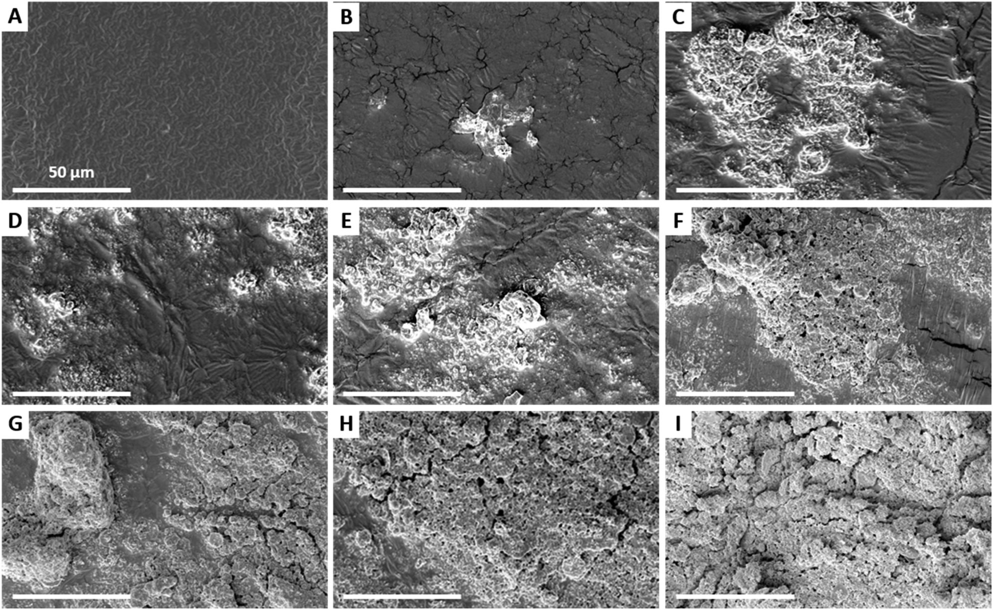 | ||
| Fig. 6 High (×2500) magnification SEM images of uncoated and HA–BG coated films obtained with a fixed deposited suspension volume (20 μL cm−2) and increasing suspension concentrations: (A) uncoated film; (B) 1 mg mL−1; (C) 5 mg mL−1; (D) 10 mg mL−1; (E) 15 mg mL−1; (F) 20 mg mL−1; (G) 25 mg mL−1; (H) 35 mg mL−1; (I) 50 mg mL−1. | ||
For suspension concentrations lower than 10 mg mL−1 (coating density ≤ 0.2 mg cm−2), high magnification observations showed that most if not all HA–BG aggregates are embedded in the PBT films (Fig. 6B–D). For suspension concentrations greater than 15 mg mL−1 (coating density ≥ 0.3 mg cm−2), stacks of piled-up aggregates were observed in the coated areas, as can be seen in Fig. 6E–I. The number and size of these stacks increases with the coating density. For the highest coating densities, V20_C35 and V20_C50, large clusters of particles were visible even at low magnification (Fig. 6H–I). The coverage rate, defined as the fraction of surface covered by HA–BG particles, was measured quantitatively by image analysis of low magnification SEM images (see Experimental section). It increased with the increasing coating density as shown in Fig. 7. In particular, data from 0 to 0.7 mg cm−2 were well fitted by a linear fit (R2 = 0.991) suggesting that the onset of full coverage is achieved for a coating density of 0.9 mg cm−2.
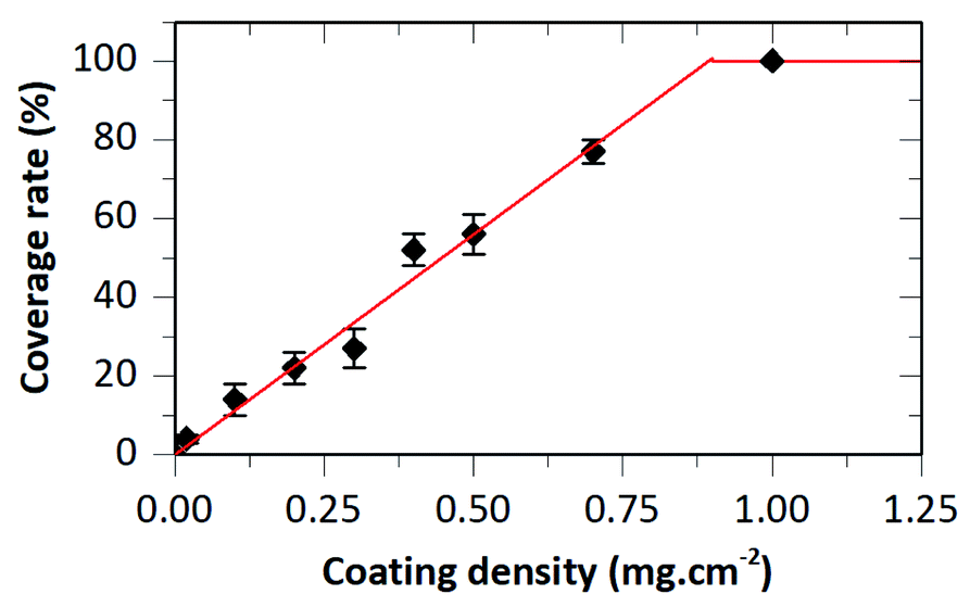 | ||
| Fig. 7 Coverage rate as a function of the coating density for samples obtained with a fixed deposited suspension volume (20 μL cm−2) and increasing suspension concentration. Full line is a linear fit (slope: 112% mg−1 cm2). | ||
3.3. Degradability of HA–BG coatings
The degradability of HA–BG coatings was assessed by immersing V20_C10 films in PBS at physiological pH and temperature (pH 7.4, 37 °C). The coated surface of the films was observed by SEM after various immersion times from 2 h to 21 days, as shown in Fig. 8A–F. After 2 h immersion (Fig. 8B), the coated surface looked very similar to the one before immersion in PBS (Fig. 8A). From 7 to 21 days of immersion however, we observed a gradual disappearance of particles from the surface of the films (Fig. 8C–F).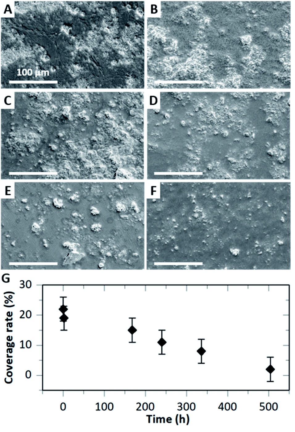 | ||
| Fig. 8 Degradation of HA–BG coatings on V20_C10 films after immersion in PBS at 37 °C and pH 7.4. (A–F) SEM images of HA–BG coated surfaces: before (A) and after immersion for (B) 2 h, (C) 7 days, (D) 10 days, (E) 14 days and (F) 21 days. Magnification: ×250. (G) Evolution of the coverage rate measured by image analysis as a function of immersion time. | ||
Measurements of the coverage rate by image analysis as a function of immersion time confirmed this progressive degradation of the HA–BG coating (Fig. 8G). The value of the coverage rate after 2 h immersion (19 ± 4%) was not significantly different from the one before (22 ± 4%). However, for longer times, we measured a significant and gradual decrease of the coverage rate reaching 15% after 7 days and down to 2% after 21 days. Such a rate of degradation is consistent with the slow dissolution of HA microspheres in PBS as measured by El Fiqi et al.28 Using inductively coupled plasma atomic emission technique, these authors monitored the ionic release of Ca, P and Si. Ca and P release was sustained over 28 days, with a rate of 0.29 mM per day for Ca the first three days and 28 μM per day after.
3.4. Ex vivo adhesion on liver tissues
The adhesion on biological tissues of uncoated and coated PBT films was investigated ex vivo by 90° peeling experiments on the capsule of pig livers. In these experiments, a 1 cm-wide PBT ribbon was put in contact for 5 min with the liver capsule and was then peeled at constant speed (1 mm s−1) and constant 90° angle (see details in the Experimental section).The drainage of interfacial fluids needs to be considered when measuring adhesion between polymers films and tissues.47 For each experiment, the swelling of the PBT films was measured by weighing the ribbons after peeling. We verified that after 5 min of contact the swelling ratio is very low (1.03), well below equilibrium swelling (1.54). Such values of adsorbed liquid on the ex vivo liver capsule correspond to an adhesive regime where all the interfacial fluid has been drained.47
Fig. 9A shows typical peeling force–displacement curves for an uncoated ribbon and a HA–BG coated ribbon having a coating density of 0.2 mg cm−2 (V10_C20). For the uncoated film, a normalized peeling force of 4 ± 1 N m−1 was obtained while it was two to three times higher for the HA–BG coated film at 11 ± 1 N m−1. Accordingly, the HA–BG coated film produced a larger deformation of the liver at the peeling front than the uncoated one (Fig. 9B). The corresponding adhesion energies G, given by the mean peeling forces normalized by the ribbon width, are presented in Fig. 9C for a series of peeling tests repeated on several livers (n = 6). We found that adhesion was significantly enhanced in the presence of the HA–BG coating (p = 0.0004), with G going from 4.6 ± 0.8 J m−2 for the uncoated films to 9.8 ± 1.5 J m−2 for the coated ones.
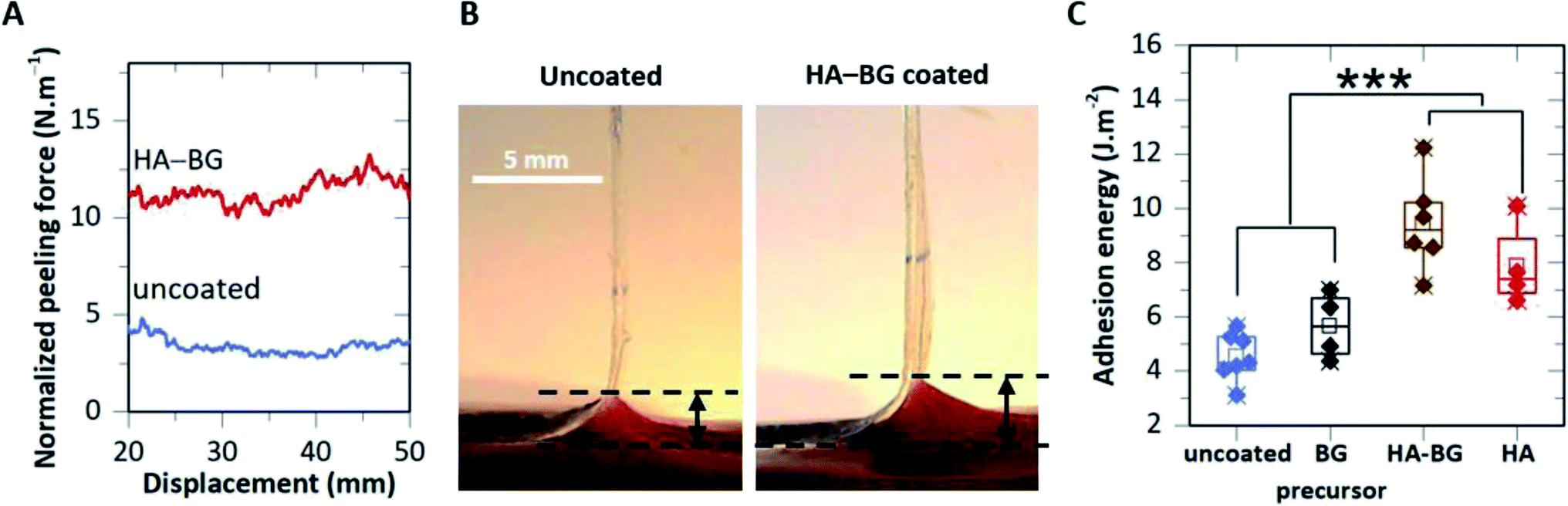 | ||
| Fig. 9 Ex vivo tissue adhesion. (A) Peeling force normalized by the ribbon width as a function of peeling displacement for uncoated and HA–BG coated films (coating density: 0.2 mg cm−2). (B) Side view of the peeling zones for the same uncoated and coated films as in (A). Black arrows indicate the extent of liver deformation during detachment. (C) Adhesion energy of uncoated films and films coated with BG precursor, HA–BG and HA (coating density: 0.2 mg cm−2). | ||
These adhesive performances were compared to those of PBT films coated by pure HA microparticles and BG precursors particles using the exact same coating parameters (Fig. 9C). The adhesion produced by the HA coating was slightly lower (G = 7.9 ± 1.5 J m−2) but not significantly different from the one obtained with the HA–BG coating (p = 0.19). On the contrary, the BG precursors coating did not produce any significant adhesion enhancement with an adhesion energy of G = 5.6 ± 1.2 J m−2. These results show that HA flower-like microparticles within the HA–BG coating are the major contributors to the particle bridging effect between the PBT films and the liver capsule. They also indicate that the incorporation of some 400 nm BG spherical particles within the HA particles does not alter significantly this adhesion. Such a difference in adhesion may be attributed to the difference in the accessible surface area which is much larger for the nanostructured HA particles (SSA = 26 m2 g−1) than for the densely packed BG precursors (SSA below BET resolution).
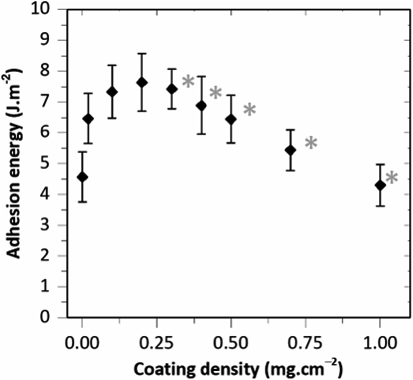
The adhesion produced by HA–BG coatings was investigated in another series of experiments as a function of the coating density, with coating densities varying from 0.02 to 1.0 mg cm−2. For that, HA–BG coated ribbons were produced with the coatings presented in Fig. 5. The evolution of the adhesion energy G as a function of the coating density is presented in Fig. 10 where each data point is the mean value of 3 to 7 peeling tests realized on a total of 6 livers. A maximum in adhesion energy clearly appears. For the lowest coating densities, adhesion energy increased starting from 4.5 ± 0.8 J m−2 for the uncoated films up to 7.6 ± 0.8 J m−2 for 0.2 mg cm−2. For coating densities greater than 0.2 mg cm−2, the adhesion energy decreased rather linearly with increasing coating density reaching 4.3 ± 0.7 J m−2 for 1.0 mg cm−2.
 | ||
| Fig. 10 Adhesion energy as a function of the coating density (fixed deposited suspension volume 20 μL cm−2). Each data point is an average over 3 to 7 peeling tests. Error bars correspond to the standard deviation. Gray stars indicate conditions for which a transfer of particles onto the liver was detected by in situ microscopy during peeling. | ||
For each peeling test, the surfaces of the film and liver capsule were examined during peeling using a long working distance microscope. For coating densities lower than 0.2 mg cm−2, no transfer of HA–BG particles from the coating to the capsule was detected, as shown on Fig. 11A for a coating density of 0.2 mg cm−2. This is confirmed by SEM observations of the ribbon surfaces after peeling which show no significant alteration of the coatings, as illustrated in Fig. 11B for a coating density of 0.2 mg cm−2. The coverage rate of the coating after peeling (34 ± 7%) measured by analysis of SEM images on an area of 1 mm2, was comparable to the one before peeling (22 ± 4%). On the contrary, for all the coating densities higher than 0.3 mg cm−2, a transfer of HA–BG particles from the coating to the liver surface was observable during peeling, as shown in Fig. 11C for 0.3 mg cm−2. For the highest coating densities, this transfer was visible to the naked eye on the liver surface, as shown in Fig. 11D in the case of the 0.5 mg cm−2 coating. Despite this transfer, SEM observations after peeling indicated that the films were still covered with particles, and the coverage rate measured by analysis of SEM images remained unchanged (51 ± 7% after peeling vs. 56 ± 4% before peeling for 0.5 mg cm−2 and 100% before and after peeling for 1.0 mg cm−2, see Fig. S7†).
 | ||
| Fig. 11 (A) Microscopic observations of the detachment at the peeling front for a coating density of 0.2 mg cm−2. (B) SEM observation after peeling of the same coating as in (A) (magnification ×500). (C) Microscopic observations of the detachment at the peeling front for a coating density of 0.3 mg cm−2. (D) Picture after peeling of the same surface liver for a coating density of 0.5 mg cm−2. (E) Schematic representation of the two detachment regimes for coating densities below (i) and above (ii) the maximum in adhesion energy. | ||
Interestingly, these results show that the maximum in adhesion energy is reached for a surface coverage (∼20%) well below the surface saturation. In addition, this maximum in adhesion energy coincides with the occurrence of particle transfer and with the observations of piled-up HA–BG aggregates for coating densities above 0.2 mg cm−2. Based on these observations, we propose a simple microscopic picture explaining the non-monotonic evolution of the adhesion energy as a function of the coating density. For that, we distinguish two regimes as follows.
For coating densities lower than 0.2 mg cm−2, a monolayer of particles is deposited on the film. Therefore, most particles actively contribute to adhesion by particle bridging upon contact with the liver capsule. Assuming that particle–film binding is stronger than particle–tissue binding, peeling produces an adhesive separation where particles remain firmly attached to the film, as depicted in Fig. 11E(i). In this regime, an increase in coating density causes an increase in the number of actively binding particles, which in turn produces an increase in adhesion energy.
For coating densities greater than 0.2 mg cm−2, stacks of several particle aggregates were formed in the coated areas. We assume that interactions between HA–BG aggregates are much weaker than the physical binding resulting from macromolecular adsorption at the particle–film and particle–tissue interfaces. As a result, these multiple layers of particles introduce weak interfaces and separation during peeling occurs through a combination of two local processes, as depicted in Fig. 11E(ii). In areas coated with a monolayer of particles, adhesive separation occurs by detachment of actively bridging particles from the tissue while in areas coated with stacks of aggregates, a cohesive rupture occurs within the coating. This latter mechanism leads to the transfer of particles from the coating to the tissue and is responsible for the reduction in adhesion energy. Such a picture is also consistent with previous results obtained with microscopic aggregates of 10 nm diameter silica nanoparticles deposited by brush spreading on a PEG hydrogel film.7 In this system, a high coating density was achieved (1.7 ± 0.4 mg cm−2) and a large excess of poorly attached aggregates was observed, which led to a strong reduction in adhesion energy.
The maximum values of adhesion energy on ex vivo liver capsule obtained with the studied HA–BG coated films reach 9.8 ± 1.5 J m−2 and 7.6 ± 0.8 J m−2 for V10_C20 and V20_C10, respectively. These values are comparable to the best adhesion energies on ex vivo liver capsule reported for PEG films fully coated by aggregates of silica nanoparticles using brush spreading: 10 ± 5 J m−2 for 30 nm plain silica nanoparticles and 11 ± 3 J m−2 for 50 nm mesoporous silica nanoparticles.7 It is also worth to notice that this maximum adhesion with HA–BG coatings was obtained below full coverage. Therefore, HA–BG particles seem to be particularly efficient as bridging connectors. This ability may be explained by the affinity of the particles for both biological tissues and PBT films. On the one side, adsorption of macromolecules from the extra-cellular matrix (ECM) on HA was previously reported,31,32 as well as attractive interactions between BG and collagen.20 On the other side, it has been described that van der Waals interactions and H-bonds are formed when PEG macromolecules are adsorbed on HA particles.55 Similar interactions are expected between HA and PBT chains which consist in an alternation of a PEG skeleton and thiols moieties. Furthermore, it is well known that surface nano- and micro-structuration enhances the adhesion of ECM proteins on biomaterials.56 Here, the flower-like nano-structuration of HA particles offers a large accessible surface for the adsorption of macromolecular chains.
As regards the biocompatibility, the toxicity of HA and BG coatings has already been assessed and reviewed,57,58 especially in the field of bone regeneration. In particular, particles synthesized following the bioinspired protocol by Fiqi et al. were shown to be not cytotoxic at 24 h or 48 h on mesenchymal stem cells.28,59 In the context of bioadhesive coatings, the toxicity risk is further reduced by the fact that the quantities are very low. In the present study, the typical amount of particles used for the HA–BG coatings is of the order of 0.2 mg cm−2, which corresponds to 2 mg for a 10 cm2 adhesive surface. Considering a human body, this represents a dose of 0.02–0.04 mg kg−1, which is several orders of magnitude lower than the doses (0.1 g kg−1) of hydroxyapatite or bioactive glass particles typically implanted in animal models for drug delivery purposes or bone defect fillers.60–62
4. Conclusions
As a conclusion, we have used the partial mineralization of bioactive glass precursors in order to obtain mixed HA–BG particles, with the goal to fabricate tissue adhesive coatings. The proposed deposition process by particle suspension spreading provides a simple method to adjust the density of the coatings, which is of utmost importance for the efficiency of adhesion. Patterned coatings were obtained which could be of interest to enhance the permeability of the interface and facilitate exchanges between the tissue and the polymer substrate. Using adhesion tests on the porcine liver capsule, we show that the adhesion energy depends non-monotonically on the coating density. Microscopic characterization explains this relationship between adhesion energy and coating microstructure by the presence of aggregate stacks that introduce weak interparticle interfaces and favour cohesive rupture within the coating. With the studied systems and methods, the maximum adhesion energy was reached for a particle concentration of 0.2 mg cm−2, corresponding to a coverage rate of 22%. Above this concentration, multiple layers of particle aggregates which are deleterious to adhesion are formed locally on the PBT film surface. We also show that HA–BG coatings progressively degrade in physiological fluids until almost complete dissolution of particles within 21 days. Such a mixed coating valorises the most of both components, i.e. the adhesive potential of HA and the rapid degradation of BG, which could be of interest for the topical delivery of active substances on surgical dressings or implant surfaces. In particular, the composition of BG within the HA–BG coatings could be tailored to favour its dissolution63 and to add properties through ion and drug release, such as antioxidant,64 antibacterial65 or antibiofouling effects.66Author contributions
E. Palierse and M. Roquart contributed equally to this work.Estelle Palierse: conceptualization, investigation, formal analysis, visualization, validation, writing – original draft. Maïlie Roquart: conceptualization, investigation, formal analysis, visualization, validation, writing – original draft. Sophie Norvez: investigation, supervision, validation, writing – original draft. Laurent Corté: funding acquisition, investigation, project administration, conceptualization, supervision, validation, writing – original draft.
Conflicts of interest
There are no conflicts to declare.Acknowledgements
We thank Maria Simoes and Fabrice Gaslain (CMAT, MINES Paris - PSL) as well as Bruno Bresson (SIMM, ESPCI Paris - PSL) for technical assistance on SEM as well as the SEM platform of IPGG and ESPCI Paris. We thank Vanessa Pereira Pimenta (IMAP, ESPCI Paris – PSL, ENS – PSL) for assistance and discussion on BET analysis. Financial support of the French National Research Agency (ANR-18-CE19-0022-04 NanoBioTape), MINES Paris – PSL and ESPCI Paris – PSL is gratefully acknowledged.References
- W. Zhang, R. Wang, Z. Sun, X. Zhu, Q. Zhao, T. Zhang, A. Cholewinski, F. (Kuo) Yang, B. Zhao, R. Pinnaratip, P. K. Forooshani and B. P. Lee, Chem. Soc. Rev., 2020, 49, 433–464 RSC.
- J. Li, A. D. Celiz, J. Yang, Q. Yang, I. Wamala, W. Whyte, B. R. Seo, N. V. Vasilyev, J. J. Vlassak, Z. Suo and D. J. Mooney, Science, 2017, 357, 378–381 CrossRef CAS PubMed.
- H. Yuk, C. E. Varela, C. S. Nabzdyk, X. Mao, R. F. Padera, E. T. Roche and X. Zhao, Nature, 2019, 575, 169–174 CrossRef CAS PubMed.
- C. Heinzmann, C. Weder and L. M. de Espinosa, Chem. Soc. Rev., 2016, 45, 342–358 RSC.
- S. Rose, A. Prevoteau, P. Elzière, D. Hourdet, A. Marcellan and L. Leibler, Nature, 2014, 505, 382–385 CrossRef CAS PubMed.
- M. T. Matter, F. Starsich, M. Galli, M. Hilber, A. A. Schlegel, S. Bertazzo, S. E. Pratsinis and I. K. Herrmann, Nanoscale, 2017, 9, 8418–8426 RSC.
- R. Michel, M. Roquart, E. Llusar, F. Gaslain, S. Norvez, J. S. Baik, G.-R. Yi, M. Manassero and L. Corté, ACS Appl. Bio Mater., 2020, 3, 8808–8819 CrossRef CAS PubMed.
- K. Shin, J. W. Choi, G. Ko, S. Baik, D. Kim, O. K. Park, K. Lee, H. R. Cho, S. I. Han, S. H. Lee, D. J. Lee, N. Lee, H.-C. Kim and T. Hyeon, Nat. Commun., 2017, 8, 1–12 CrossRef CAS PubMed.
- H. Wu, F. Li, S. Wang, J. Lu, J. Li, Y. Du, X. Sun, X. Chen, J. Gao and D. Ling, Biomaterials, 2018, 151, 66–77 CrossRef CAS PubMed.
- M. Lu, J. Bai, D. Shao, J. Qiu, M. Li, X. Zheng, Y. Xiao, Z. Wang, Z. Chang, L. Chen, W. Dong and C. Tang, Int. J. Nanomed., 2018, 13, 5849–5863 CrossRef CAS PubMed.
- S. Nam and D. Mooney, Chem. Rev., 2021, 121, 11336–11384 CrossRef CAS PubMed.
- A. Meddahi-Pellé, A. Legrand, A. Marcellan, L. Louedec, D. Letourneur and L. Leibler, Angew. Chem., 2014, 126, 6487–6491 CrossRef.
- Y. Gao, Y. Han, M. Cui, H. L. Tey, L. Wang and C. Xu, J. Mater. Chem. B, 2017, 5, 4535–4541 RSC.
- D. Napierska, L. C. Thomassen, D. Lison, J. A. Martens and P. H. Hoet, Part. Fibre Toxicol., 2010, 7, 39 CrossRef CAS PubMed.
- P. Singh, A. Anand and V. Kumar, Eur. J. Med. Chem., 2014, 85, 758–777 CrossRef CAS PubMed.
- X. Dong, Z. Wu, X. Li, L. Xiao, M. Yang, Y. Li, J. Duan and Z. Sun, Int. J. Nanomed., 2020, 15, 9089–9113 CrossRef CAS PubMed.
- J.-H. Kim, H. Kim, Y. Choi, D. S. Lee, J. Kim and G.-R. Yi, ACS Appl. Mater. Interfaces, 2017, 9, 31469–31477 CrossRef CAS PubMed.
- Q. Zeng, K. Han, C. Zheng, Q. Bai, W. Wu, C. Zhu, Y. Zhang, N. Cui and T. Lu, J. Colloid Interface Sci., 2022, 607, 1239–1252 CrossRef CAS PubMed.
- L.-C. Gerhardt and A. R. Boccaccini, Materials, 2010, 3, 3867–3910 CrossRef CAS PubMed.
- R. Oréfice, L. Hench and A. Brennan, J. Biomed. Mater. Res., Part A, 2009, 90, 114–120 CrossRef PubMed.
- S. Kargozar, R. K. Singh, H.-W. Kim and F. Baino, Acta Biomater., 2020, 115, 1–28 CrossRef CAS PubMed.
- S. Kargozar, S. Hamzehlou and F. Baino, Materials, 2017, 10, 1429 CrossRef PubMed.
- V. Miguez-Pacheco, L. L. Hench and A. R. Boccaccini, Acta Biomater., 2015, 13, 1–15 CrossRef CAS PubMed.
- I. Lese, C. Tsai, M. Matter, T. Wüthrich, H. S. Scheer, A. Taddeo, M. A. Constantinescu, I. K. Herrmann and R. Olariu, ACS Biomater. Sci. Eng., 2021, 7, 2676–2686 CrossRef CAS PubMed.
- M. Vallet-Regi and J. M. Gonzalez-Calbet, Prog. Solid State Chem., 2004, 32, 1–31 CrossRef CAS.
- K. Lin, C. Wu and J. Chang, Acta Biomater., 2014, 10, 4071–4102 CrossRef CAS PubMed.
- W. Qiao, X. Lan, J. K. H. Tsoi, Z. Chen, R. Y. X. Su, K. W. K. Yeung and J. P. Matinlinna, RSC Adv., 2017, 7, 44788–44798 RSC.
- A. El-Fiqi, J. O. Buitrago, S. H. Yang and H.-W. Kim, Acta Biomater., 2017, 60, 38–49 CrossRef CAS PubMed.
- Z. Xu, C. Liu, J. Wei and J. Sun, J. Appl. Toxicol., 2012, 32, 429–435 CrossRef CAS PubMed.
- J. M. Sadowska and M.-P. Ginebra, J. Mater. Chem. B, 2020, 8, 9404–9427 RSC.
- F. Wu, D. D. W. Lin, J. H. Chang, C. Fischbach, L. A. Estroff and D. Gourdon, Cryst. Growth Des., 2015, 15, 2452–2460 CrossRef CAS PubMed.
- M. Tagaya, T. Ikoma, T. Takemura, N. Hanagata, T. Yoshioka and J. Tanaka, Langmuir, 2011, 27, 7645–7653 CrossRef CAS PubMed.
- M. Okada, A. Nakai, E. S. Hara, T. Taguchi, T. Nakano and T. Matsumoto, Acta Biomater., 2017, 57, 404–413 CrossRef CAS PubMed.
- Y. Sugiura, M. Okada, K. Hirano and T. Matsumoto, Adv. Mater. Interfaces, 2021, 8, 2002032 CrossRef CAS.
- V. Stanić, S. Dimitrijević, J. Antić-Stanković, M. Mitrić, B. Jokić, I. B. Plećaš and S. Raičević, Appl. Surf. Sci., 2010, 256, 6083–6089 CrossRef.
- S. Shanmugam and B. Gopal, Ceram. Int., 2014, 40, 15655–15662 CrossRef CAS.
- K. Zawisza, P. Sobierajska, N. Nowak, A. Kedziora, K. Korzekwa, B. Pozniak, M. Tikhomirov, J. Miller, L. Mrowczynska and R. J. Wiglusz, Mater. Sci. Eng., C, 2020, 106, 110295 CrossRef CAS PubMed.
- S. Kargozar, M. Montazerian, S. Hamzehlou, H.-W. Kim and F. Baino, Acta Biomater., 2018, 81, 1–19 CrossRef CAS PubMed.
- S. Seyedmajidi, M. Seyedmajidi, E. Zabihi and K. Hajian-Tilaki, J. Biomed. Mater. Res., Part A, 2018, 106, 2605–2612 CrossRef CAS PubMed.
- Y. Seo, T. Goto, S. H. Cho, S. Shi, A. Žarkov, T. Yamamoto and T. Sekino, Ceram. Int., 2020, 46, 25520–25526 CrossRef CAS.
- H. Ghomi, M. H. Fathi and H. Edris, Mater. Res. Bull., 2012, 47, 3523–3532 CrossRef CAS.
- C. V. Ragel, M. Vallet-Regí and L. M. Rodríguez-Lorenzo, Biomaterials, 2002, 23, 1865–1872 CrossRef CAS PubMed.
- H. Abe, Y. Hara, S. Maeda and S. Hashimoto, J. Phys. Chem. B, 2014, 118, 2518–2522 CrossRef CAS PubMed.
- S. Cereceres, Z. Lan, L. Bryan, M. Whitely, T. Wilems, N. Fabela, C. Whitfield-Cargile and E. Cosgriff-Hernandez, Ann. Biomed. Eng., 2020, 48, 953–967 CrossRef PubMed.
- N. Zaquen, B. Wenn, K. Ranieri, J. Vandenbergh and T. Junkers, J. Polym. Sci., Part A: Polym. Chem., 2014, 52, 178–187 CrossRef CAS.
- E. D. Strange, M. P. Dahms, R. C. Benedict and J. H. Woychik, J. Food Sci., 1985, 50, 1484–1485 CrossRef.
- R. Michel, L. Poirier, Q. van Poelvoorde, J. Legagneux, M. Manassero and L. Corté, Proc. Natl. Acad. Sci. U. S. A., 2019, 116, 738–743 CrossRef CAS PubMed.
- A.E. Rydholm, C.N. Bowman and K.S. Anseth, Biomaterials, 2005, 26, 4495–4506 CrossRef CAS PubMed.
- K. Kendall, J. Phys. D: Appl. Phys., 1975, 8, 1449–1452 CrossRef.
- W. Stöber, A. Fink and E. Bohn, J. Colloid Interface Sci., 1968, 26, 62–69 CrossRef.
- R. D. Deegan, O. Bakajin, T. F. Dupont, G. Huber, S. R. Nagel and T. A. Witten, Nature, 1997, 389, 827–829 CrossRef CAS.
- D. Mampallil and H. B. Eral, Adv. Colloid Interface Sci., 2018, 252, 38–54 CrossRef CAS PubMed.
- A. T. Tyowua and A. I. Ezekwuaku, Colloids Surf., A, 2021, 629, 127386 CrossRef CAS.
- B. M. Weon and J. H. Je, Phys. Rev. E: Stat., Nonlinear, Soft Matter Phys., 2010, 82, 015305 CrossRef PubMed.
- D. Yamini, G. Devanand Venkatasubbu, J. Kumar and V. Ramakrishnan, Spectrochim. Acta, Part A, 2014, 117, 299–303 CrossRef CAS PubMed.
- S. A. Skoog, G. Kumar, R. J. Narayan and P. L. Goering, Pharmacol. Ther., 2018, 182, 33–55 CrossRef CAS PubMed.
- J. N. Oliver, Y. Su, X. Lu, P.-H. Kuo, J. Du and D. Zhu, Bioact. Mater., 2019, 4, 261–270 CrossRef PubMed.
- A. Bral and M. Y. Mommaerts, J. Cranio-Maxillofac. Surg., 2016, 44, 400–412 CrossRef PubMed.
- A. El-Fiqi, T.-H. Kim, M. Kim, M. Eltohamy, J.-E. Won, E.-J. Lee and H.-W. Kim, Nanoscale, 2012, 4, 7475 RSC.
- B. Kundu, D. Ghosh, M. K. Sinha, P. S. Sen, V. K. Balla, N. Das and D. Basu, Ceram. Int., 2013, 39, 9557–9566 CrossRef CAS.
- V. I. Chissov, I. K. Sviridova, N. S. Sergeeva, G. A. Frank, V. A. Kirsanova, S. A. Achmedova, I. V. Reshetov, M. M. Filjushin, S. M. Barinov, I. V. Fadeeva and V. S. Komlev, Bull. Exp. Biol. Med., 2008, 146, 139–143 CrossRef CAS PubMed.
- C. Mao, X. Chen, Q. Hu, G. Miao and C. Lin, Mater. Sci. Eng., C, 2016, 58, 682–691 CrossRef CAS PubMed.
- S. Naseri, W. C. Lepry and S. N. Nazhat, J. Mater. Chem. B, 2017, 5, 6167–6174 RSC.
- K. Zheng, E. Torre, A. Bari, N. Taccardi, C. Cassinelli, M. Morra, S. Fiorilli, C. Vitale-Brovarone, G. Iviglia and A. R. Boccaccini, Mater. Today Bio, 2020, 5, 100041 CrossRef PubMed.
- T. Mehrabi and A. S. Mesgar, Colloids Surf., B, 2022, 212, 112338 CrossRef CAS PubMed.
- K. Zheng, B. Sui, K. Ilyas and A. R. Boccaccini, Mater. Horiz., 2021, 8, 300–335 RSC.
Footnote |
| † Electronic supplementary information (ESI) available. See https://doi.org/10.1039/d2ra02781j |
| This journal is © The Royal Society of Chemistry 2022 |