 Open Access Article
Mechanism of the Fe(III)-catalyzed synthesis of hexahydropyrimidine with α-phenylstyrene: a DFT study†
Yaxuan Cheng,
Siwei Yang ,
Chaoyu Zhao
 and
Huiling Liu
 *
*
Laboratory of Theoretical and Computational Chemistry, Institute of Theoretical Chemistry, College of Chemistry, Jilin University, Liutiao Road 2, Changchun 130023, China. E-mail: huiling@jlu.edu.cn
First published on 15th July 2022
Abstract
It is very important to develop multiple C–H substitution reactions of simple alkenes to obtain complex unsaturated components. The present study focuses on a theoretical investigation of the plausible mechanism in the Fe(OTf)3-catalyzed tandem amidomethylative reactions of α-phenylstyrene. Bis(tosylamido)methane is activated by Fe(OTf)3 to form tosylformaldimine and its Fe(OTf)3-adduct. The Fe(OTf)3-adduct undergoes an intermolecular aza-Prins reaction with α-phenylstyrene to form allylamide. The DFT data support the formation of the hexahydropyrimidine derivative from allylamide, and “condensation/iminium homologation/intramolecular aza-Prins” is the optimal reaction path. At the same time, a possible reaction pathway for the conversion of the hydrolysate 1,3-diamide derivative to the hexahydropyrimidine (HHP) derivative is given. This work is thus instructive for understanding Fe(III)-based tandem catalysis for the amidomethylative multiple-substitution reactions of alkenes.
1. Introduction
Nitrogen heterocyclic compounds are widely found in nature and have good bioactivity and reactivity.1–3 Among them, hexahydropyrimidines (HHPs) are promising compounds due to their important role in obtaining natural molecules, drugs and bioactive compounds.4–8 Consequently, the search for more efficient synthesis approaches to obtain HHP and its derivatives has become a research hotspot.In the past few years, researchers have developed a number of methods to synthesize HHPs with different substituted groups. Among them, the classical method utilizes the condensation of aldehydes or ketones with 1,3-diaminopropanes.9–11 Based on this, Katritzky et al. prepared N,N′-unsymmetrically substituted HHPs through the cyclocondensation property of benzotriazole.12 Subsequently, Khan et al. reported several novel 1,2,3-trisubstituted HHP derivatives, which were further prepared by the reaction of 1,3-diaminopropanes with different formaldehyde substitutes.13 Due to the proposal of green chemistry, the concept of pursuing atom economy, process economy and environmental friendliness in chemical synthesis has been widely adopted.14 Multicomponent reactions (MCRs) can meet the above requirements to a large extent.15–19 In 2007, Liang et al. synthesized 1,3-diaryl-5-spirohexahydropyrimidines by a one-pot reaction using anilines, formaldehyde, and cyclohexanones.20 In the same year, Farrell et al. synthesized novel phenol-derivatized HHPs by the Mannich reaction.21 Meanwhile, Mukhopadhyay and colleagues synthesized 1,3-diaryl-HHPs catalysed by FeCl3 in DCM in a one-pot reaction through the multicomponent approach using 1,3-dicarbonyl compounds, amines and formaldehyde.22 In 2012, In(OTf)3 as a reusable Lewis acid catalyst for the synthesis of spiro-HHP scaffolds was first reported. This is a three-component system consisting of aromatic amines, formaldehyde, and cyclic ketones as substrates.23 Although the above studies on the synthesis of HHPs have their own merits, they mainly focus on the reaction of C![[double bond, length as m-dash]](https://www.rsc.org/images/entities/char_e001.gif) O bonds and primary amines. In 2017, Cui et al. investigated the acid-catalyzed [2 + 2 + 2] system for HHPs, which overcame the challenge of insufficient nucleophilicity of the iminium species using the intermolecular aza-Prins reaction24–27 and directly synthesizing the target product from the alkene precursor.28 On the basis of this mechanism detection experiment, Fang et al. calculated the possible reaction mechanisms, catalytic species, and regioselectivity in the cycloaddition reaction for this system using density functional theory.29 These studies provide a good theoretical basis for the tandem reaction and new ideas for the synthesis of HHP and its derivatives.
O bonds and primary amines. In 2017, Cui et al. investigated the acid-catalyzed [2 + 2 + 2] system for HHPs, which overcame the challenge of insufficient nucleophilicity of the iminium species using the intermolecular aza-Prins reaction24–27 and directly synthesizing the target product from the alkene precursor.28 On the basis of this mechanism detection experiment, Fang et al. calculated the possible reaction mechanisms, catalytic species, and regioselectivity in the cycloaddition reaction for this system using density functional theory.29 These studies provide a good theoretical basis for the tandem reaction and new ideas for the synthesis of HHP and its derivatives.
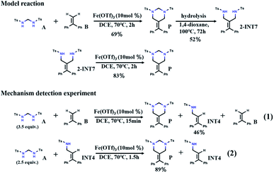
Recently, inspired by the above [2 + 2 + 2] tandem cycloaddition reaction30–34 catalytic pathway, Cui et al. reported a tandem amidomethylative reaction catalyzed by Fe(III).35 When multiple amidomethylation steps occurred through the elimination of the recovered C![[double bond, length as m-dash]](https://www.rsc.org/images/entities/char_e001.gif) C bonds, HHPs were directly synthesized from α-substituted styrene derivatives. As shown in Scheme 1, the yield of HHP (P) from the reaction of bis(tosylamido)methane (A) and α-phenylstyrene (B) is 69% (DCE = 1,2-dichloroethane, 70 °C, 2 h). Under hydrolysis conditions, P can form 52% 1,3-diamide derivative (2-INT7) (1,4-dioxane, 100 °C, 72 h). Interestingly, 2-INT7 can also generate P in 83% yield (DCE, 70 °C, 2 h). To understand the reaction mechanism, Cui et al. further performed probing experiments. After reacting for 15 min, the reaction of A and B was interrupted to generate the allylamide (INT4) with a yield of 46%. A continued to react with INT4 for 1.5 hours to obtain P with a yield of 89%. Based on the above analysis of the experimental results, we speculate that there may be another path (A + B → INT4 → 2-INT7 → P), which has aroused our interest in its further exploration. Here, we hope to find supportive reaction pathways through DFT computation and investigate some details of the catalytic mechanism at the molecular level, which will help us gain insight into the reaction mechanism of the tandem amidomethylation of alkenes.
C bonds, HHPs were directly synthesized from α-substituted styrene derivatives. As shown in Scheme 1, the yield of HHP (P) from the reaction of bis(tosylamido)methane (A) and α-phenylstyrene (B) is 69% (DCE = 1,2-dichloroethane, 70 °C, 2 h). Under hydrolysis conditions, P can form 52% 1,3-diamide derivative (2-INT7) (1,4-dioxane, 100 °C, 72 h). Interestingly, 2-INT7 can also generate P in 83% yield (DCE, 70 °C, 2 h). To understand the reaction mechanism, Cui et al. further performed probing experiments. After reacting for 15 min, the reaction of A and B was interrupted to generate the allylamide (INT4) with a yield of 46%. A continued to react with INT4 for 1.5 hours to obtain P with a yield of 89%. Based on the above analysis of the experimental results, we speculate that there may be another path (A + B → INT4 → 2-INT7 → P), which has aroused our interest in its further exploration. Here, we hope to find supportive reaction pathways through DFT computation and investigate some details of the catalytic mechanism at the molecular level, which will help us gain insight into the reaction mechanism of the tandem amidomethylation of alkenes.
2. Computational methods
In the present study, we used Fe(OTf)3 as the catalyst and bis(tosylamido)methane (A) and α-phenylstyrene (B) as reactants for the model reaction. All geometries were fully optimized at the B3LYP-D3(BJ)/BSI level.29,36–38 BSI denotes the SDD39 pseudopotential for Fe and the 6-31G(d,p) basis set for all nonmetal atoms. Intrinsic reaction coordinate (IRC)40,41 calculations were carried out to verify the transition structures connecting the substrates and products. The single-point energies of the reactants, transition states, intermediates and products in the two potential reaction paths were calculated. Single-point energy calculations were performed on the stationary points using the SMD model42 and DCE (1,2-dichloroethane, ε = 10.1)/BSII level (the basis set of SDD for Fe and 6-311++G(d,p) for nonmetal atoms). All calculations were performed using the Gaussian 09 D.01 package.43 Molecular structures were visualized using CYLview.44 Contents related to the electronic structures were analyzed by Multiwfn.45,463. Results and discussion
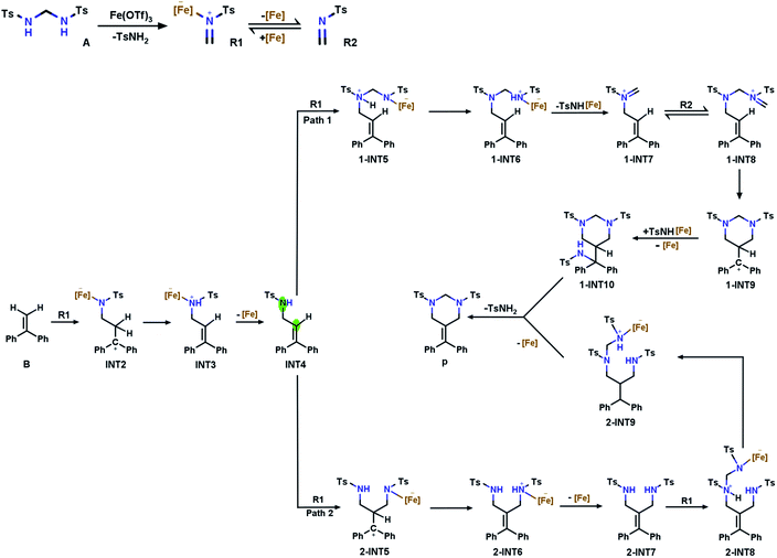
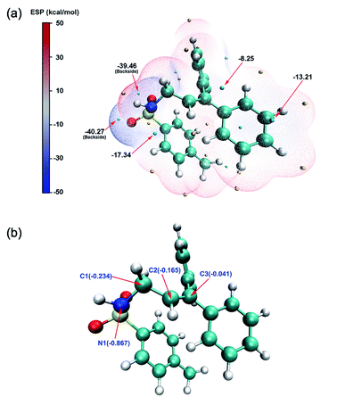
Based on the report by Cui et al., we propose two potential pathways for the model reaction (Fig. 1). The first step describes the generation of tosylformaldimine (R2) and its Fe(OTf)3-adduct (R1). Subsequently, the intermolecular reaction (aza-Prins) between R1 and α-phenylstyrene (B) to form allylamide (INT4) occurs.In order to explore the reaction mechanisms, we first performed an electrostatic potential analysis (ESP)47 on INT4 (Fig. 2a) to determine the possible reaction sites and further predict the potential reaction pathways. The ESP results show that above the carbon–carbon double bond and the nitrogen atom, there are regions with a negative electrostatic potential, which can easily be attacked by electrophiles. At the same time, due to the influence of the oxygen atom's solitary nature on electrons, there is an intersecting area above the nitrogen and oxygen atoms, which makes the electrostatic potential value (−17.34 kcal mol−1) here smaller than that above the carbon–carbon (−8.25 kcal mol−1) double bond. Through the ESP analysis above, it is seen that N1 and C2 are both nucleophilic and easily attacked by electrophiles. However, the optimal reaction site has not yet been determined. Therefore, we further used natural population analysis (NPA) to determine the optimal reaction site (Fig. 2b). According to the NPA charge analysis of INT4, the N1 atom has a more negative charge value (−0.867) than the C2 (−0.165) atom, which clearly shows that N1 is more vulnerable to electrophilic attack and is the optimal reaction site in INT4.
At this point, R1 has two competitive options: pathway 1, where R1 attacks the N1 atom in INT4, and pathway 2, where R1 attacks the C2 atom on the double bond in INT4. We have determined the optimal pathway through DFT calculations, and the specific analysis will be introduced in the following subsections.
3.1 Tosylformaldimine release reaction
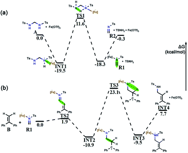
Bis(tosylamido)methane (A) is readily synthesized under alkaline conditions and can be activated by Lewis acids to form formaldimine. In this process, the main role of Fe(OTf)3 is to promote the activation of bis(tosylamido)methane to form tosylformaldimine. Based on a previous [2 + 2 + 2] cyclic addition mechanism study,48 an intermolecular aza-Prins process should be followed in this reaction, which requires the catalyst to react with A first to release R2. The free energy profile for the whole tosylformaldimine release reaction process is shown in Fig. 3a, where the total free energy of A and Fe(OTf)3 is set to the reference energy. Since the N atom in A has a lone electron pair and can coordinate with the catalyst, the catalyst Fe(OTf)3 combines with A to produce the intermediate INT1, in which the negative charge is focussed on the Fe site and the positive charge is focussed on the adjacent N atom. Then, the intermediate INT1 undergoes a process involving C–N bond breaking along with hydrogen transfer to generate R1. This process needs to overcome an energy barrier of 31.1 kcal mol−1, and the reaction free energy is 1.2 kcal mol−1. Meanwhile, we also tried to use A as a base to deliver protons, but the protons to be delivered are encased inside the molecule INT1 (Fig. S1†), and due to steric hindrance, there was no place for A to form a six-membered ring transition state. Therefore, using A as a base for delivering protons was not successful. Eventually, Fe(OTf)3 departed from R1 to generate R2, with a reaction free energy of 18.0 kcal mol−1. From Fig. 3a, we can observe that the rate-determining step of R2 being released from A is a hydrogen transfer process, which has a relatively high energy barrier and requires a certain temperature for the reaction to occur.3.2 Intermolecular aza-Prins reaction
After R1 is released from A in the previous step, the nucleophile B attacks the atom C1 in R1, completing the intermolecular aza-Prins reaction. The free energy profile for the whole intermolecular aza-Prins reaction process is shown in Fig. 3b, where the total free energy of B and R1 is set to the reference energy. The complexation of R1 and B undergoes nucleophilic addition via a transition state TS2 with a low energy barrier of 1.9 kcal mol−1, which indicates that the process is extremely easy to proceed. Subsequently, the atom N1 in INT2 undergoes protonation and a hydrogen is transferred from the C2 to N1, which needs to overcome an energy barrier of 34.0 kcal mol−1. In Cui's experiments, the HHP (P) yield was low (less than 70%) and was not improved by increasing the reaction temperature (70 °C/90 °C/110 °C). Our calculation results show that the energy difference between the initial state INT2 and the final state INT3 is very small (only 1.4 kcal mol−1), which indicates that the yield will not increase with the increase in temperature, and so the activation energy barrier of 34.0 kcal mol−1 required from the initial state INT2 and the final state INT3 is feasible. As shown in Fig. S1,† the distance of the nitrogen–hydrogen bond is shortened from 2.805 Å in INT2 to 1.433 Å in TS3. This indicates that higher energy barriers need to be crossed at the hydrogen transfer stage. The distance from C2 to H2 in TS3 is 1.363 Å. Finally, C![[double bond, length as m-dash]](https://www.rsc.org/images/entities/char_e001.gif) C is formed in INT4 as the catalyst Fe(OTf)3 leaves from INT3.
C is formed in INT4 as the catalyst Fe(OTf)3 leaves from INT3.
3.3 Catalytic pathways begin with condensation and aza-Prins
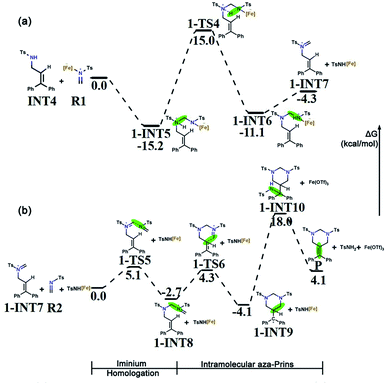
B undergoes an intermolecular aza-Prins reaction to form INT4. In the subsequent tandem step of INT4, R1 has two competing options in the subsequent tandem steps: a condensation reaction or another aza-Prins reaction. Experimentally, it is difficult to compare these two competing behaviours. Here, we calculated the energies of the reactants, products and transition states, and analyzed them according to their activation energy. In the following sections, the elemental steps for the two competing pathways will be discussed in detail.The first part of the condensation reaction. The free energy profile for the whole condensation reaction process is shown in Fig. 4a, where the total free energy of INT4 and R1 is set to the reference energy. INT4 forms 1-INT5 on its N-center with R1, and no transition state is found in this process. The free energy of 1-INT5 is 15.2 kcal mol−1 lower than that of the reactant (INT4 + R1), indicating that this step is favored thermodynamically. Subsequently, the hydrogen atom on the N1 atom in 1-INT5 is transferred to the N2 atom to form 1-INT6. This hydrogen transfer step requires overcoming an energy barrier of 30.2 kcal mol−1. The broken N1–H3 bond distance increases from 1.029 Å in 1-INT5 to 2.450 Å in 1-INT6 and the formed N2–H3 bond shortens from 2.528 Å in 1-INT5 to 1.033 Å in 1-INT6 (Fig. S1†). The next step is the departure of TsNH[Fe] to provide 1-INT7. Although this step is an endergonic process, the free energy difference between the reactant and product is only 6.8 kcal mol−1, which means that this stage is still feasible. In addition, the bond length between N1 and C4 in 1-INT7 is 1.274 Å (between N1 and C4 in 1-INT6 is 1.425 Å), which indicates that after TsNH[Fe] is separated, a double bond is formed between carbon and nitrogen.
Iminium homologation. In the second part of the tandem path 1, the iminium homologation reaction occurs. R2 attacks the C4 in 1-INT7 and the C4
![[double bond, length as m-dash]](https://www.rsc.org/images/entities/char_e001.gif) N1 bond (1.274 Å) breaks to form the C4–N1 bond (1.500 Å) through the transition state 1-TS5 to produce 1-INT7's iminium homolog 1-INT8. As shown in Fig. S1,† the distance between N3 and C4 in the transition state 1-TS5 is 2.001 Å. Here, a single bond is formed. The energy barrier to be overcome is 5.1 kcal mol−1 and the energy difference between the reactant and product is only 2.7 kcal mol−1, indicating that this is a reversible process and the conversion between the two intermediates is very easy to achieve.
N1 bond (1.274 Å) breaks to form the C4–N1 bond (1.500 Å) through the transition state 1-TS5 to produce 1-INT7's iminium homolog 1-INT8. As shown in Fig. S1,† the distance between N3 and C4 in the transition state 1-TS5 is 2.001 Å. Here, a single bond is formed. The energy barrier to be overcome is 5.1 kcal mol−1 and the energy difference between the reactant and product is only 2.7 kcal mol−1, indicating that this is a reversible process and the conversion between the two intermediates is very easy to achieve.
Intramolecular aza-Prins reaction. In the last part, an intramolecular aza-Prins reaction occurs in the intermediate 1-INT8. In this process, the C5 atom in 1-INT8 attacks the C2 atom on styrene to form a closed six-membered ring, which only needs to overcome a low energy barrier of 7.0 kcal mol−1. The distance between C5 and C2 is reduced from 3.300 Å to 1.595 Å (Fig. S1†). The difference in free energy between the reactant 1-INT8 and the product 1-INT9 is 1.4 kcal mol−1, making this intramolecular aza-Prins reaction extremely easy to carry out. The TsNH[Fe] isolated from the condensation reaction attacks the carbocation in the intermediate 1-INT9, the hydrogen atom is transferred and the carbocation is captured, and the product P is obtained. In this process, 1-INT10 is 22.1 kcal mol−1 higher than 1-INT9. The free energy profile for the iminium homologation and intramolecular aza-Prins reaction process is shown in Fig. 4b, where the total free energy of 1-INT7, R2 and TsNH[Fe] is set to the reference energy.
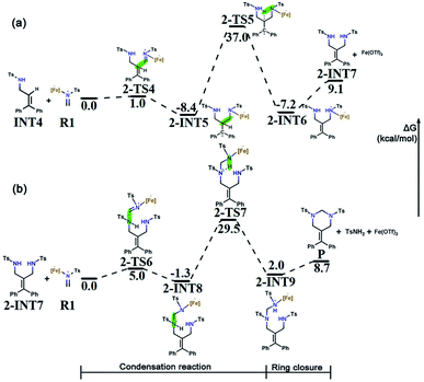
Intermolecular aza-Prins reaction. Similar to the formation of INT4, R1 electrophilically attacks the C2 atom in INT4 to form 2-INT5, and the intermolecular aza-Prins reaction occurs again. The free energy profile for the whole intermolecular aza-Prins reaction process is shown in Fig. 5a, where the total free energy of INT4 and R1 is set to the reference energy. This reaction has an exergonic free energy of −8.4 kcal mol−1. Moreover, the energy barrier to be overcome in this process via the transition state 2-TS4 is only 1.0 kcal mol−1. As shown in Fig. S2,† the distance between C6 and N4 increases from 1.277 Å in R1 to 1.451 Å in 2-INT5, and the double bond is broken to form a single bond. In addition, the hydrogen transfer in 2-INT5 overcomes an energy barrier of 45.4 kcal mol−1 to obtain the intermediate 2-INT6, from which the catalyst Fe(OTf)3 is separated. The rate-determining step of this stage is the hydrogen transfer process, which is kinetically unfavorable as it needs to cross an energy barrier of 45.4 kcal mol−1.
Condensation reaction. The goal in this part is to introduce a carbon atom on 2-INT7, which is achieved using the condensation between R1 and 2-INT7. The condensation of 2-INT7 and R1 only has a 5.0 kcal mol−1 energy barrier to overcome, and the difference in free energy between the products and the reactants is very small. As shown in Fig. S2,† the distance between C7 and N4 is 1.556 Å in 2-INT8, and this condensation reaction forms a single bond. Nevertheless, the energy barrier (30.8 kcal mol−1) to overcome for hydrogen transfer after the formation of intermediate 2-INT8 is relatively high. Therefore, the reaction requires a high temperature and a long time.
Six-membered ring closure. The C7 in 2-INT9 is connected to N1 to achieve a six-membered ring closure reaction. There is no transition state in the above process. The catalyst Fe(OTf)3 and TsNH2 are separated, and the target product P is obtained by the direct ring closure of 2-INT9. The energy difference between the reactant and product is only 6.7 kcal mol−1, indicating that this process is easy to implement. The free energy profile for the condensation reaction and the six-membered ring closure process is shown in Fig. 5b, where the total free energy of 2-INT7 and R1 is set to the reference energy.
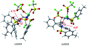
In summary, the results compared through theoretical calculations show that pathway 1, starting with a condensation reaction, is preferable to pathway 2, starting with the aza-Prins reaction because the INT4 + R1 → 1-INT5 stage in pathway 1 has a greater exergonic free energy (6.8 kcal mol−1) than the INT4 + R1 → 2-INT5 stage in pathway 2. Moreover, the Laplacian bond order (LBO) is a parameter that can measure the bond strength in organic systems. We calculated the LBO for the N–H bond in 1-INT5 and the C–H bond in 2-INT5, and obtained the values 0.79 and 0.87 (Fig. 6), respectively. This means that the cleavage of the C–H bond in the 2-INT5 → 2-INT6 process requires a higher energy than the cleavage of the N–H bond in the 1-INT5 → 1-INT6 process. Thus, the 2-INT5 → 2-INT6 stage in pathway 2 has a higher reaction energy barrier (15.2 kcal mol−1) than the 1-INT5 → 1-INT6 stage in pathway 1. Therefore, the N1 site serves as the optimal reaction site for INT4 and has nucleophilicity. Pathway 1, starting with the condensation reaction, is thus the preferred mechanism. A and B react to form P. The hydrolysis product 2-INT7 can also form P, which is consistent with Cui's experimental results.
4. Conclusions
In this work, the calculation details of the mechanism of the reaction between bis(tosylamido)methane (A) with α-phenylstyrene (B) catalyzed by Fe(OTf)3 are clarified based on density functional theory. The analysis of electrostatic potential shows that the two reaction sites N1 and C2 in allylamide (INT4) are both nucleophilic, leading to two competing reaction pathways. Further, according to NPA charge analysis, the N1 site shows more negative charge, is more vulnerable to R1 electrophilic attack, and is the optimal site for the reaction. Through the reaction energy barriers of each step for the two competing reaction pathways, and the analysis and comparison of the reaction energy, it has been determined that pathway 1 is the preferred mechanism. The preferred catalyzed mechanism consists of five parts: (1) tosylformaldimine (R2) and its Fe(OTf)3-adduct (R1) are released from A; (2) an intermolecular aza-Prins reaction produces INT4; (3) a condensation reaction to form 1-INT7; (4) iminium homologation to form 1-INT8; (5) an intramolecular reaction to form HHP (P). In this tandem reaction, A and B generate P via the intermediate INT4. Additionally, we found that the hydrolysis product 1,3-diamide derivative (2-INT7) can also undergo a condensation and ring closure reaction to generate P.Conflicts of interest
There are no conflicts to declare.References
- A. Dhakshinamoorthy and H. Garcia, Chem. Soc. Rev., 2014, 43, 5750–5765 RSC.
- M. Zhang, Q. Wang, Y. Peng, Z. Chen, C. Wan, J. Chen, Y. Zhao, R. Zhang and A. Q. Zhang, Chem. Commun., 2019, 55, 13048–13065 RSC.
- P. C. Sharma, K. K. Bansal, A. Sharma, D. Sharma and A. Deep, Eur. J. Med. Chem., 2020, 188, 112016 CrossRef CAS PubMed.
- T. Gossas, H. Nordström, M.-H. Xu, Z.-H. Sun, G.-Q. Lin, H. Wallberg and U. H. Danielson, Med. Chem. Commun., 2013, 4, 432–442 RSC.
- Y. Ochi, S. Yokoshima and T. Fukuyama, Org. Lett., 2016, 18, 1494–1496 CrossRef CAS PubMed.
- B. M. Williams and D. Trauner, Angew. Chem., Int. Ed., 2016, 55, 2191–2194 CrossRef CAS PubMed.
- T. Kang, S. Gao, L. X. Zhao, Y. Zhai, F. Ye and Y. Fu, J. Agric. Food Chem., 2021, 69, 45–54 CrossRef CAS PubMed.
- R. W. Sabnis, ACS Med. Chem. Lett., 2021, 12, 679–680 CrossRef CAS PubMed.
- R. F. Evans, Aust. J. Chem., 1967, 20, 1643–1661 CrossRef CAS.
- D. J. Bergmann, E. M. Campi, W. R. Jackson, Q. J. Mccubbin and A. F. Patti, Tetrahedron, 1997, 53, 17449–17460 CrossRef CAS.
- J. M. Locke, R. Griffith, T. D. Bailey and R. L. Crumbie, Tetrahedron, 2009, 65, 10685–10692 CrossRef CAS.
- A. R. Katritzky, S. K. Singh and H. Y. He, J. Org. Chem., 2002, 67, 3115–3117 CrossRef CAS PubMed.
- M. S. Y. KHAN and M. GUPTA, Pharmazie, 2002, 57, 377–383 CAS.
- R. C. Cioc, E. Ruijter and R. V. A. Orru, Green Chem., 2014, 16, 2958–2975 RSC.
- E. Ruijter, R. Scheffelaar and R. V. Orru, Angew. Chem., Int. Ed., 2011, 50, 6234–6246 CrossRef CAS PubMed.
- A. Bhunia, S. R. Yetra and A. T. Biju, Chem. Soc. Rev., 2012, 41, 3140–3152 RSC.
- C. de Graaff, E. Ruijter and R. V. A. Orru, Chem. Soc. Rev., 2012, 41, 3969–4009 RSC.
- N. Deibl and R. Kempe, Angew. Chem., Int. Ed., 2017, 56, 1663–1666 CrossRef CAS PubMed.
- J. S. Zhang, L. Liu, T. Chen and L. B. Han, Chem.–Asian J., 2018, 13, 2277–2291 CrossRef CAS PubMed.
- H. L. Wei, Z. Y. Yan, Y. N. Niu, G. Q. Li and Y. M. Liang, J. Org. Chem., 2007, 72, 8600–8603 CrossRef CAS PubMed.
- J. R. Farrell, J. Niconchuk, C. S. Higham and B. W. Bergeron, Tetrahedron Lett., 2007, 48, 8034–8036 CrossRef CAS.
- C. Mukhopadhyay, S. Rana and R. J. Butcher, Tetrahedron Lett., 2011, 52, 4153–4157 CrossRef CAS.
- A. Dandia, A. K. Jain and S. Sharma, Tetrahedron Lett., 2012, 53, 5270–5274 CrossRef CAS.
- D. M. Kaphan, F. D. Toste, R. G. Bergman and K. N. Raymond, J. Am. Chem. Soc., 2015, 137, 9202–9205 CrossRef CAS PubMed.
- D. H. Ma, Z. L. Zhong, Z. M. Liu, M. J. Zhang, S. Y. Xu, D. Y. Xu, D. P. Song, X. G. Xie and X. G. She, Org. Lett., 2016, 18, 4328–4331 CrossRef CAS PubMed.
- J. F. Bai, K. Yasumoto, T. Kano and K. Maruoka, Chem. – Eur. J., 2018, 24, 10320–10323 CrossRef CAS PubMed.
- X. Y. Liu, F. P. Wang and Y. Qin, Acc. Chem. Res., 2021, 54, 22–34 CrossRef CAS PubMed.
- H. Zhou, H. Handi, C. Lakmal, J. M. Baine, H. U. Valle, X. Xu and X. Cui, Chem. Sci., 2017, 8, 6520–6524 RSC.
- R. Fang, Y. C. Zhang, A. M. Kirillov and L. Z. Yang, J. Org. Chem., 2020, 85, 3676–3688 CrossRef CAS PubMed.
- G. Dominguez and J. Perez-Castells, Chem. Soc. Rev., 2011, 40, 3430–3444 RSC.
- A. Roglans, A. Pla-Quintana and M. Sola, Chem. Rev., 2021, 121, 1894–1979 CrossRef CAS PubMed.
- W. K. Samba, R. Tia and E. Adei, J. Phys. Org. Chem., 2021, 35, 1 Search PubMed.
- C. S. Wang, Q. Sun, F. Garcia, C. Wang and N. Yoshikai, Angew. Chem., Int. Ed., 2021, 60, 9627–9634 CrossRef CAS PubMed.
- T. Yasui, R. Tatsumi and Y. Yamamoto, ACS Catal., 2021, 11, 9479–9484 CrossRef CAS.
- X. L. Qian, H. Zhou, H. H. C. Lakmal, J. Lucore, X. S. Wang, H. U. Valle, B. Donnadieu, X. Xu and X. Cui, ACS Catal., 2020, 10, 10627–10636 CrossRef CAS.
- A. D. Becke, J. Chem. Phys., 1993, 98, 5648–5652 CrossRef CAS.
- X. Zhang and K. Wang, RSC Adv., 2015, 5, 34439–34446 RSC.
- A. R. Firooz, M. Movahedi and H. Sabzyan, Mater. Sci. Eng., C, 2019, 94, 410–416 CrossRef CAS PubMed.
- D. Andrae, U. H. U. Ermann, M. Dolg, H. Stoll and H. Preu, Theor. Chim. Acta, 1990, 77, 123–141 CrossRef CAS.
- K. Fukui, J. Phys. Chem., 1970, 74, 4161–4163 CrossRef CAS.
- K. Fukui, Acc. Chem. Res., 1981, 14, 363–368 CrossRef CAS.
- A. V. Marenich, C. J. Cramer and D. G. Truhlar, J. Phys. Chem. B, 2009, 113, 6378–6396 CrossRef CAS PubMed.
- M. J. Frisch, G. W. Trucks, H. B. Schlegel, G. E. Scuseria, M. A. Robb, J. R. Cheeseman, G. Scalmani, V. Barone, B. Mennucci, G. A. Petersson, H. Nakatsuji, M. Caricato, X. Li, H. P. Hratchian, A. F. Izmaylov, J. Bloino, G. Zheng, J. L. Sonnenberg, M. Hada, M. Ehara, K. Toyota, R. Fukuda, J. Hasegawa, M. Ishida, T. Nakajima, Y. Honda, O. Kitao, H. Nakai, T. Vreven, J. A. Montgomery Jr., J. E. Peralta, F. Ogliaro, M. Bearpark, J. J. Heyd, E. Brothers, K. N. Kudin, V. N. Staroverov, T. Keith, R. Kobayashi, J. Normand, K. Raghavachari, A. Rendell, J. C. Burant, S. S. Iyengar, J. Tomasi, M. Cossi, N. Rega, J. M. Millam, M. Klene, J. E. Knox, J. B. Cross, V. Bakken, C. Adamo, J. Jaramillo, R. Gomperts, R. E. Stratmann, O. Yazyev, A. J. Austin, R. Cammi, C. Pomelli, J. W. Ochterski, R. L. Martin, K. Morokuma, V. G. Zakrzewski, G. A. Voth, P. Salvador, J. J. Dannenberg, S. Dapprich, A. D. Daniels, O. Farkas, J. B. Foresman, J. V. Ortiz, J. Cioslowski and D. J. Fox, Gaussian 09, Revision D.01, Gaussian Inc., Wallingford CT, 2013 Search PubMed.
- C. Y. Legault, CYLview20, Université De Sherbrooke, 2020 Search PubMed.
- T. Lu and F. Chen, Acta Chim. Sin., 2011, 69, 2393–2406 CAS.
- T. Lu and F. Chen, J. Comput. Chem., 2012, 33, 580–592 CrossRef CAS PubMed.
- T. Lu and F. W. Chen, J. Mol. Graphics Modell., 2012, 38, 314–323 CrossRef CAS PubMed.
- Z. Y. Li, H. H. C. Lakmal and X. Cui, Org. Lett., 2019, 21, 3735–3740 CrossRef CAS PubMed.
Footnote |
| † Electronic supplementary information (ESI) available. See https://doi.org/10.1039/d2ra02727e |
| This journal is © The Royal Society of Chemistry 2022 |

