
 Open Access Article
 This Open Access Article is licensed under a Creative Commons Attribution-Non Commercial 3.0 Unported Licence
Enhanced transformation of CO2 over microporous Ce-doped Zr metal–organic frameworks†
Juan Baia,
Ziwei Song *a,
Lijuan Liua,
Xu Zhua,
Faming Gaoa and
Raghunath V. Chaudhari*b
*a,
Lijuan Liua,
Xu Zhua,
Faming Gaoa and
Raghunath V. Chaudhari*b
aHebei Key Laboratory of Applied Chemistry, School of Environmental and Chemical Engineering, Yanshan University, Qinhuangdao 066004, China
bCenter for Environmentally Beneficial Catalysis, Department of Chemical & Petroleum Engineering, University of Kansas, 1530 W15th Street, Lawrence, Kansas 66045, USA
First published on 15th September 2022
Abstract
Metal–organic frameworks (MOF) have been studied extensively for the adsorption and catalytic conversion of CO2. However, previous studies mainly focused on the adsorption capabilities of partially or totally Ce substituted UiO-66, there are few studies focusing on transformation of the structure and catalytic activity of these materials. In this work, a series of Zr/Ce-based MOFs with UiO-66 architecture catalysts were prepared for the conversion of CO2 into value-added dimethyl carbonate (DMC). Owing to the different addition order of the two metals, significantly varied shapes and sizes were observed. Accordingly, the catalytic activity is greatly varied by adding a second metal. The different catalytic activities may arise from the different acid–base properties after Ce doping as well as the morphology and shape changes. Besides, the formation of terminal methoxy (t-OCH3) was found to be the rate limiting step. Finally, the reaction mechanism of CO2 transformation in the presence of a dehydrating agent was proposed.
Introduction
As the major greenhouse gas leading to global warming, carbon dioxide (CO2) has attracted a lot of attention from both academic and industry communities. The development of efficient methods to convert CO2 into value-added chemicals is the key to realize a carbon-neutral society.1,2 CO2 can be used as an environmental friendly C1 feedstock for its high natural abundance, easy availability and environment benign properties.3,4 However, for its inherent inertness, only a few processes using CO2 have been successfully commercialized.5 To overcome the inertness, high-energy starting materials are usually used, such as hydrogen, alkylene oxides, low-carbon, and organometallic rings, etc.6–9 Choosing low-energy synthetic targets, such as organic carbonates, is also a crucial strategy to convert CO2. As the simplest organic carbonate, DMC has drawn a lot of attention due to its easy degradation, low toxicity and effective substitution of phosgene, dimethyl sulfate and methyl halide in organic synthesis processes.10,11 And the direct synthesis of DMC from CO2 and CH3OH has become one of the most attractive processes (as shown in Scheme 1(a)).12–14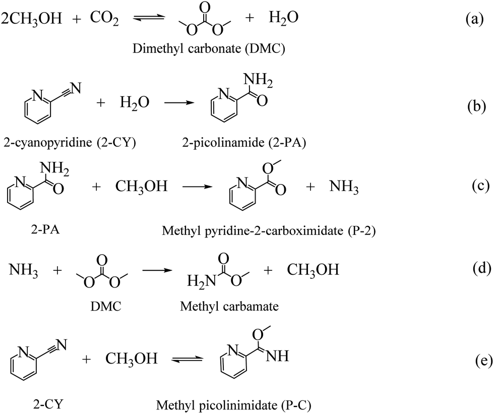 | ||
| Scheme 1 Reactions involved in the reaction of CO2 and MeOH with 2-cyanopyridine as dehydrating agent. | ||
The direct catalytic conversion of CO2 to DMC is simple, clean and with high atom efficiency. But because of the extreme thermodynamic limitation, achieving high DMC yield is still challenging.15 Besides, the H2O formed during the reaction leads to the easily deactivation of the catalysts. To overcome these challenges, various catalytic systems have been developed, such as ionic liquids,16,17 alkali carbonates,18,19 metal oxides,20,21 supported metal oxides,22 heteropoly acids,23 metal–organic frameworks,24,25 etc. Among these catalysts, metal–organic frameworks (MOFs) show a promising prospect.
MOFs are porous materials formed by metal ions or metal clusters with organic bridging linkers, showing a diverse range of potential applications, such as used for gas adsorption, catalysis, ionic conduction, etc.26–28 Previous studies showed that MOFs offer excellent capacities of CO2 uptake due to its ultra-high surface areas.29 MOFs can also be used as catalyst for CO2 conversion.27 The extreme stable UiO-66 was reported to be active for the conversion of CO2 with 100% selectivity of DMC without dehydrating agent, but with a low DMC yield of around 0.015%.30 Studies demonstrated that the catalytic activity of MOFs could be tuned by introducing/substituting the functional group in an organic linker.31,32 Xuan K. and co-workers modified UiO-66 (Zr) with trifluoroacetic acid (TFA), a higher DMC yield (∼0.084%) was observed, which could be attributed to the increased number of active sites and the enlargement of porosity originated from TFA modulation.30 In addition, the exchange of the metal ions in UiO-66 by Hf, Ti and Ce could also be used to adjust the catalytic activity of MOFs. Vasudeva and co-workers found that after changing Zr to Hf in the nods of UiO-66, the TOF of the material for solketal synthesis increased from 153 h−1 to 13![[thin space (1/6-em)]](https://www.rsc.org/images/entities/char_2009.gif) 886 h−1, increased by 90 times.33
886 h−1, increased by 90 times.33
Owing to its high oxygen mobility, easy and reversible transition between Ce4+ and Ce3+, introducing Ce into MOF materials has also been implemented.34,35 Nouar et al. partially substituted Zr in UiO-66 by Ce, leading to easy catalytic decomposition of the methanol, which can be attributed to structural defects and redox activity generated from the introduction of Ce.35 Besides, Stawowy's research found that missing linker molecules in UiO-66(Ce) results in enhanced CO2 adsorption.32 All these properties obtained through Ce doping can benefit the direct conversion of CO2. However, to the best of our knowledge, previous studies mainly focused on the adsorption capabilities of partially or totally Ce substituted UiO-66, there are few studies focusing on transformation of the structure and catalytic activity of these materials. In this study, a series of UiO-66 MOFs were prepared and evaluated for the CO2 conversion to address the transformation of morphologies, structures, texture properties, and catalytic activity that caused by Ce substitution. Furthermore, the cause of the activity difference and the reaction mechanism of CO2 conversion on MOF were proposed based on experimental and characterization results.
Experimental
Materials
Zirconium chloride (ZrCl4, 98%), ammonium ceric nitrate ((NH4)2Ce(NO3)6, 99.9%), terephthalic acid (BDC, 99%), N,N-dimethylformamide (DMF, 98%), methanol anhydrous (99.0%), mesitylene (99%) and dimethyl carbonate (DMC, 99%), were purchased from Aladdin Industrial Inc. (Shanghai, China). CO2 (99.9%) and N2 (99%) were purchased from Tianjin Vista Technology Co., Ltd. All chemicals were used without further purification.Catalyst preparation
The Zr-based MOFs were prepared using the following method: 1.16 g ZrCl4 and 0.84 g terephthalic acid were fully dissolved in 125 ml of DMF, then the mixed solution was vigorously stirred for 30 min. After this, the solution was transferred into a sealed Teflon-lined autoclave and heated at 120 °C for 24 h. After cooling to room temperature, the white precipitate was collected and washed with DMF and acetone to remove the unreacted ions. Zr-MOFs were finally obtained after drying at 70 °C for 4 h. Ce-MOFs were prepared following the same procedure using (NH4)2Ce(NO3)6 as precursor.For Ce doped Zr-MOF and Zr doped Ce-MOF catalysts, the preparation procedure is as follows: 2.79 g (NH4)2Ce(NO3)6/1.16 g ZrCl4 was dissolved in 50 ml DMF and stirred for 30 min, denoted as A solution. 1.16 g ZrCl4/2.79 g (NH4)2Ce(NO3)6 and 0.84 g BDC were dissolved in 125 ml DMF and stirred for 30 min, denoted as B solution. Then A solution was dropwise added to B solution at room temperature under vigorous stirring. After this, the mixture was vigorously stirred for 30 min at room temperature. Then the same procedure as that of Zr-MOF was applied.
Catalyst characterization
Wide angle XRD patterns of the samples were collected on an X-ray Diffraction Smart Lab using Cu Kα radiation (λ = 1.5406 Å), operated at 40 kV and 30 mA with the scanning range 5–60° at a scanning rate of 5° min−1. Transmission electron microscope (TEM) of the catalyst samples were obtained on a HT770 instrument at an electron acceleration voltage of 120 kV. Scanning electron microscope (SEM) images were captured on a SUPRA 55 field-emission microscope operating at the beam energy of 10.0 kV. The sample powder was stacked on a conducting resin and sprayed with gold for 60 s to gain conductivity.The textural properties of the synthesized catalyst were determined by N2-adsorption–desorption isotherms using Autosorb iQ-Chemisorption & Physisorption Gas Sorption Analyzer. The specific surface area was evaluated by the Brunauer–Emmett–Teller (BET) method and pore size distribution of the samples was determined by the Horvath–Kawazoe (HK) method.
XPS spectra were recorded with X-ray photo electron spectrometer Escalab 250Xi apparatus with an Al-Kα X-ray source (hv = 1486.6 eV) and a monochromator. The XPS measurement was carried out in the electron binding energy ranges corresponding to carbon 1s, oxygen 1s, zirconium 3d and cerium 3d core excitations. Spectra were deconvoluted by using XPSPEAK 4.0 software. The peak was fittedusing Lorentzian–Gaussian function with an asymmetric parameter of 0.
Elemental analysis was performed over an Agilent-7700 inductively coupled plasma mass spectrometry (ICP-MS). 50 mg sample was dissolved and diluted for the analysis.
Fourier transform infrared (FT-IR) spectra for the catalyst samples were recorded in the range of 500–4000 cm−1 on a FT-IR Nicolet iS10 spectrometer. The acidity of the samples was also detected using FT-IR with pyridine as probe molecule. The catalyst samples were immersed in pyridine stream for 24 hours and then dried under vacuum at 60 °C for 8 hours. After cooling to room temperature, the FT-IR spectra of the samples were collected. Diffuse-reflectance UV-Vis absorption spectra were acquired using a UV-2550 spectrometer in the range of 200–600 nm at room temperature at a scanning wavelength interval of 0.5 nm.
Acid–base properties of the samples were studied by temperature-programmed desorption of ammonia (NH3-TPD) and temperature-programmed desorption of carbon dioxide (CO2-TPD) on a BELCAT-B instrument. Prior to adsorption, the sample was pretreated by argon (40 ml min−1) at 150 °C for 1 h. After cooling to room temperature, the argon was switched to NH3 or CO2 (40 ml min−1) for 1 h to perform the adsorptive process. The physisorbed NH3 or CO2 was then flushed by argon at room temperature for 1 h. The desorption process was conducted in argon (40 ml min−1) from room temperature to 450 °C with a heating rate of 10 °C min−1.
Catalyst activity test
The direct synthesis of DMC from CO2 and CH3OH was carried out in a 100 ml stainless-steel autoclave equipped with provisions for temperature control and agitation speed control. A schematic of the experimental setup is shown in Fig. S1.† In a typical experiment, a desired amount of CH3OH, 2-cyanopyridine (dehydrating agent), mesitylene (internal standard) and catalyst were introduced into the reactor and the mixture was purged with N2 for three times to remove the air in the sealed reactor. Then a certain amount of CO2 was charged into the reactor. After reaching the target temperature at a low stirring speed, turning the stirring rate to 900 rpm, signifying the start of the reaction.All the liquid samples were analyzed using an Agilent gas chromatography (GC-7890A) equipped with a WAX capillary column and a flame ionization detector (FID). MeOH conversion and the turn over frequency (TOF) as follows:

Results and discussion
Structure and morphology analysis
The crystalline structures of the as-synthesized MOFs have been characterized by XRD, as shown in Fig. 1(a). Typical diffraction peaks at 7.5°, 8.8° and 25.9° were detected for Zr-MOF, corresponding to the lattice planes of (111), (002) and (224) of UiO-66, indicating the successful synthesis of UiO-66 material.30,36,37 With the doping of the second metal Ce [Ce–Zr-MOF blue line in Fig. 1(a)], the intensity peaks of the material increased sharply, suggesting doping of Ce enhances the crystallinity of UiO-66 material. For the Ce-MOF, obvious diffraction peaks located at 7.2°, 8.4°, and 24.9° were also discovered, suggesting the successful formation of Ce-UiO-66.32,38 However, when trying to dope Zr in Ce-MOF using the same procedure, similar pattern as that of Ce–Zr-MOF was detected, showing that when Ce and Zr are co-existing during the preparation, Zr is more easily to be incorporated into the UiO-66 frameworks (the metal nods is mainly Zr, and Ce is existing as dopant).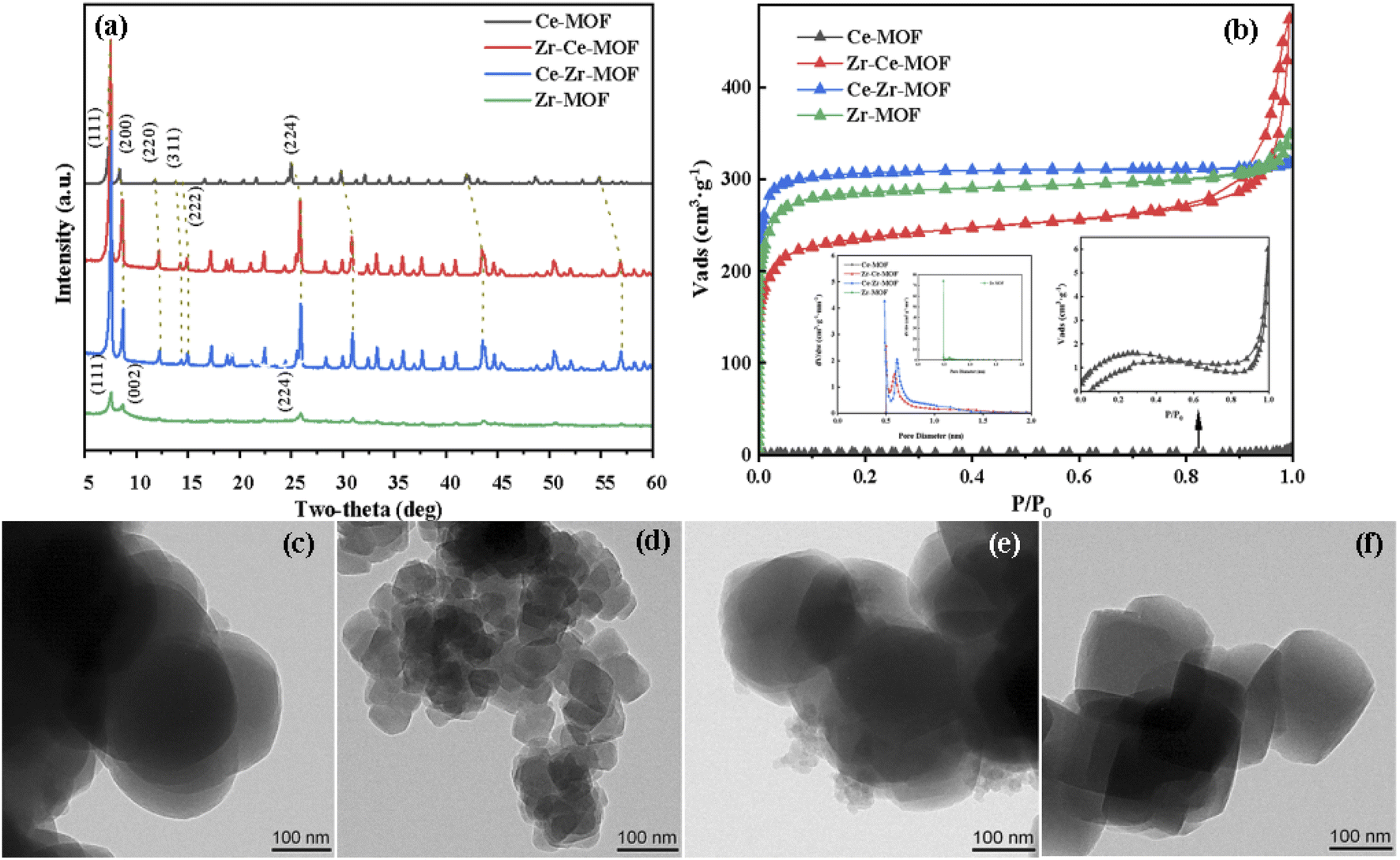 | ||
| Fig. 1 (a) XRD patterns of Zr/Ce-based MOF materials, (b) N2-adsorption–desorption isotherm, TEM images of (c) Ce-MOF; (d) Zr–Ce-MOF; (e) Ce–Zr-MOF; (f) Zr-MOF. | ||
Interestingly, with doping of Ce in the material, obvious structural distortion (blue shift in the XRD patterns) was detected, as shown in Fig. 1(a). It can be clearly seen that, with the increasing content of Ce in the materials, the distortion is more obvious. For example, the reflection angle of the (111) facet for Zr-MOF is at 7.62°, while for other three materials, the angle has shifted to 7.5° for Zr–Ce-MOF and Ce–Zr-MOF, and to 7.24° for Ce-MOF. Similar shift has also been observed for other planes, corroborating that the second metal have been successfully incorporated into the framework lattice. Specifically, lattice compression may due to the different radii of Ce4+ (0.97 Å) and Zr4+ (0.84 Å).32,39 Besides, different valence state of Ce (Ce3+) can also lead to deformation of the crystal structure. Furthermore, apparent morphology change has been observed by TEM after incorporation of Ce or Zr into the MOF materials, as shown in Fig. 1(c)–(f). Evolution from tetrahedron to spherical was detected after doping of the second metal. In addition, much smaller particle size for Zr–Ce-MOF than the other three materials was observed. The decreasing particle size indicates that the addition order of the metals plays a significantly role in the formation of the solid composite.
N2 adsorption–desorption analysis was carried out to characterize the textural properties of the samples, as shown in Fig. 1(b). The adsorption isotherms of all these catalysts exhibited type I behavior, suggesting microporous structure for all material.31,40,41 However, for the material Zr–Ce-MOF, H3 type of hysteresis loop was detected, indicating possible existing of mesopores in this material.40,42 The corresponding textural properties (BET surface area, pore volume) are listed in Table 1. It is noted that Zr-MOF showed the highest surface area (1159.00 m2 g−1) than the other three materials. However, with the introduction of Ce, the surface area began to decrease, from 1159.00 m2 g−1 to 960.40 m2 g−1 (Ce–Zr-MOF) to 757.91 m2 g−1 (Zr–Ce-MOF). Interestingly, for all the three materials, the pore size is in the same range of 0.5–1.0 nm [as shown in Fig. 1(b)], confirming again that the materials are microporous material.43 Nevertheless, there is no obvious trend for the amount of micropores. For the Ce-MOF, extremely small surface area was detected (as shown in Table 1). Ar atmosphere isothermal adsorption and desorption analysis was also performed, the results of which is shown in Table S1 (ESI†). Similar small surface area and small pore size were observed, which may result from the non-porous structure of this material, or smaller pore size of this material [smaller than the kinetic diameter of N2 (0.364 nm), N2 cannot enter into the pores, only adsorption on the surface occurred] or that the pore structure was collapsed during the N2-adsorption–desorption process. Furthermore, no obvious pore structure was observed on the surface from the SEM images (Fig. S4†), indicating super-microporous or non-porous structure of Ce-MOF. Additionally, the Ce-MOF have been prepared for three times, with nearly the same textural properties, which are also included in Table S1.†
Overall, the above results confirmed that both the single metal MOFs and the doped MOFs are successfully synthesized, all of which are crystalline microporous materials with high surface area (above 758 m2 g−1). Besides, when trying to incorporate Zr into the Ce-MOF frameworks, a tetragonal particles shape (more like Zr-MOF) was obtained. Similar phenomenon was observed for the Ce–Zr-MOF preparation, which possessed the shape of the Ce-MOF.
Optimization of CO2 to DMC conversion
Catalytic evaluation of the MOF materials as well as optimization of the reaction conditions, including temperature, pressure, reaction time and reactant/dehydrating agent ratio was carried out to improve the activity and DMC yield. Firstly, the catalytic activities of the MOF samples were measured by converting CO2 and methanol in the presence of 2-cyanopyridine (2-CY, dehydrating agent, shown in Scheme 1) at 150 °C under 2.6 MPa CO2 pressure for 6 hours (see Experimental section for details) with DMC as the target product.14,44 The catalytic methanol conversion, DMC yield and TOF of the MOF composites are displayed in Fig. 2(a). Interestingly, the conversion and activity were significantly increased when Ce was introduced into the MOF framework (Fig. 2) and then decreased when pure Ce-MOF is used (Fig. 2). In particular, Zr–Ce-MOF exhibits the highest DMC amount of 3.03 mmol and the highest TOF of 0.92 h−1. It could be noted that the DMC amount changes were closely related to Ce content (Table 2), proving that an appropriate amount of Ce can facilitate DMC production pathway. Additionally, pore volume seems to play an important role in the catalytic activity of materials.45 Surprisingly, 10.7% methanol was converted and 1.36 mmol DMC was formed without the presence of catalyst. Previous studies have shown that 2-CY not only drastically improved the carbonates yields by breaking the thermodynamic limit, it also could activate the carbonyl bond of CO2 as a catalyst.14 However, when the reaction was carried out without dehydrating agent, both the methanol conversion and DMC formation decreased significantly, indicating the critical role of dehydrating agent. In addition, the Zr–Ce-MOF material was also compared with other materials for the CO2 conversion, as shown in Table S2 in the ESI.† From the table, it is known that a relative high activity and DMC yield can be obtained over Zr–Ce-MOF under a milder reaction conditions compared to other materials. Therefore, Zr–Ce-MOF is a promising catalyst that could be used for CO2 transformation.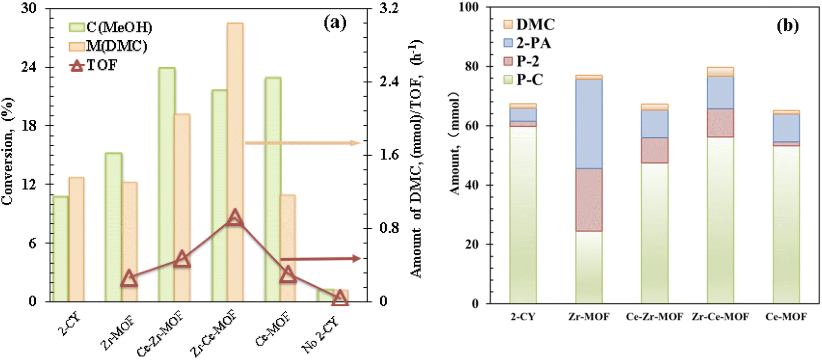 | ||
| Fig. 2 (a) Catalytic evaluation and (b) product distribution of Zr/Ce-based MOF materials. Reaction conditions: 0.5 mol MeOH, 0.25 mol 2-cyanopyridine, T = 150 °C, P = 2.6 MPa, t = 6 h. | ||
| Samples | Conc. (wt%) of elementsa | Conc. (wt%) of elementsb | Conc.a of Ce3+ (wt%) | Conc.a of Ov (wt%) | ||||
|---|---|---|---|---|---|---|---|---|
| Ce | Zr | C | O | Ce | Zr | |||
| a Concentration of Ce3+ and OV is estimated from XPS data.b Determined by ICP-MS. | ||||||||
| Ce-MOF | 34.02 | 0 | 41.72 | 24.26 | 20.97 | 0 | 62.87 | 18.67 |
| Zr–Ce-MOF | 3.83 | 17.23 | 51.31 | 27.63 | 1.16 | 23.85 | 52.37 | 28.92 |
| Ce–Zr-MOF | 1.72 | 24.44 | 45.35 | 28.49 | 1.23 | 19.62 | 19.88 | 21.89 |
| Zr-MOF | 0 | 26.25 | 44.16 | 29.59 | 0 | 17.61 | — | 19.74 |
As shown in Scheme 1, except for the hydration of 2-CY, several other reactions are also involved in the reaction system. The evolution of the formation of the chemicals with different MOF composites are displayed in Fig. 2(b). It is noted that after doping Ce, the activity for the hydration of 2-CY (blue) and reaction of 2-PA with methanol (red) was significantly decreased (total formation of 2-PA and P-2 decreased from 51.11 mmol to 17.83–20.42 mmol). In particular, when Ce-MOF was used, the reaction of 2-PA with methanol (red) diminished to nearly none, only 1.3 mmol of P-2 was formed. However, Zr-MOF has the smallest activity for the reaction of 2-CY with methanol (green), indicating there is competition for the synthesis of the side-products.
Next, the reaction temperature of the Zr–Ce-MOF catalyst was optimized from 140 °C to 170 °C [Fig. 3(a)]. When the temperature was increased, the catalytic activity first increased and then decreased, reaching an optimum DMC value at 160 °C. On the other hand, yields of by-products such as 2-PA and P-2 were also followed the same trend. But yield of P-C decreased with increasing temperature, indicating over-reactions and side reactions take place more easily at lower temperatures. As these by-products is not favorable for DMC synthesis, the optimal reaction temperature is determined to be 160 °C.
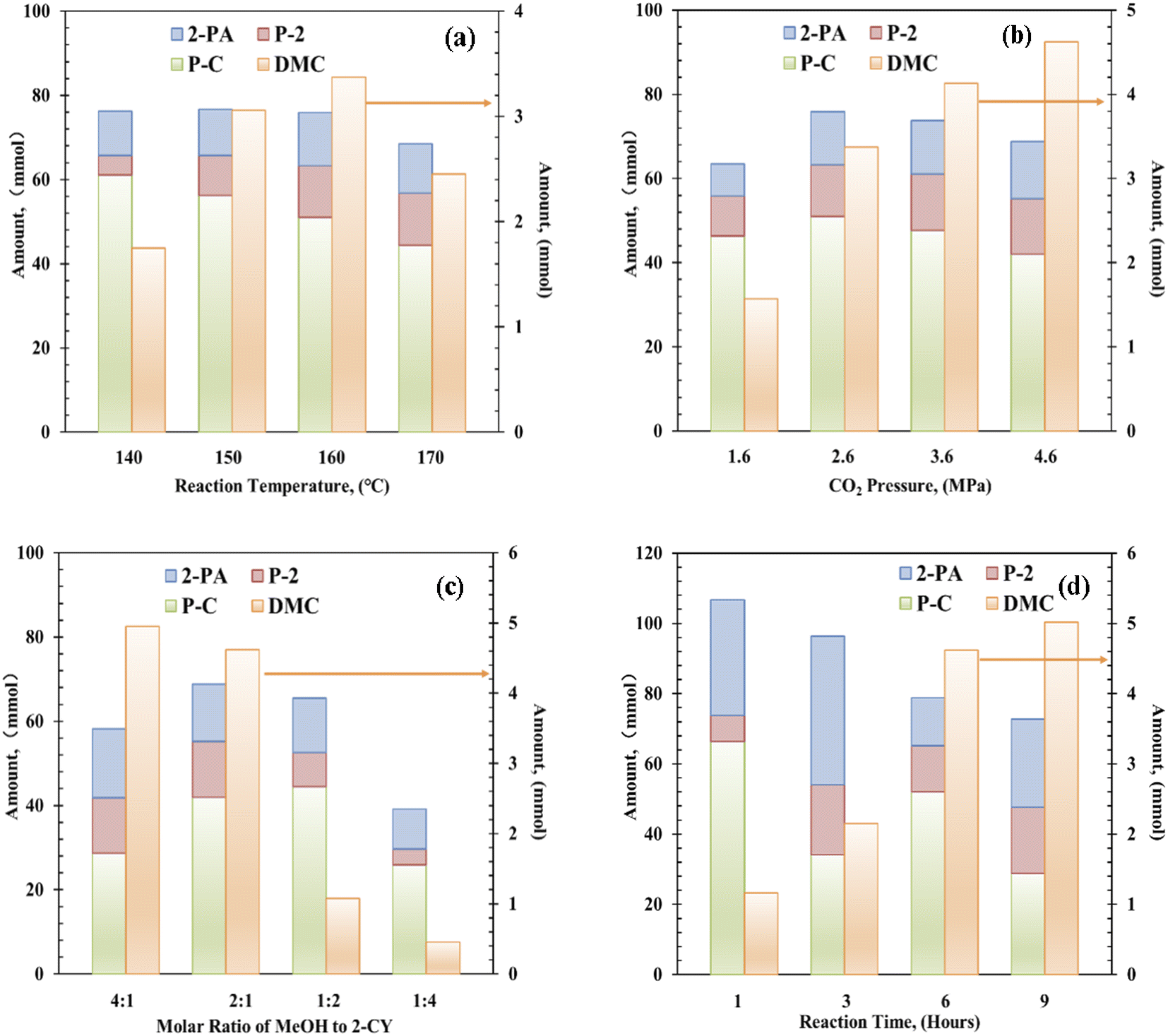 | ||
| Fig. 3 Effect of (a) reaction temperature, (b) CO2 pressure, (c) molar ratio of methanol to 2-CY, and (d) reaction time in the reaction of CH3OH + CO2 + 2-cyanopyridine system. Reaction conditions: catalyst: 0.1–0.8 g, CH3OH:2-cyanopyridine = 4:1 to 1:4, CO2: 1.6–4.6 MPa, reaction time: 1–9 h. | ||
The effect of CO2 pressure was investigated in the range of 1.6 to 4.6 MPa, and the results are shown in Fig. 3(b). DMC formation increased with increasing CO2 pressure. Moderate amount (1.57 mmol) of DMC was obtained in the presence of 1.6 MPa of CO2, and higher yield (4.62 mmol) was achieved using 4.6 MPa CO2. In contrast, the yields of these by-products were increased with increasing CO2 pressure till 2.6 MPa, then decreased with further increasing CO2 pressure. As these by-products are produced through reaction with methanol as shown in Scheme 1, and alcohol is known to be activated on acid–base pair sites.46–49 Considering that CO2 can also be strongly adsorbed on the acid–base pair sites, high pressure CO2 will suppress the formation of these by-products by covering the active sites.47,48
As for the effect of molar ratio of methanol to 2-CY, the DMC formation amount was found to be increased with increasing molar ratio. When the solar ratio of methanol to 2-CY was changed from 1:4 to 4:1, the DMC formation increased to 4.95 mmol from 0.51 mmol, while the P-C formation first increased then decreased to varying degrees. These results suggested that high MeOH concentration enhances the formation of DMC and inhibits the formation of by-products. Previous studies have also shown that the molar ratio of methanol to 2-CY plays a crucial role in the reaction.14
Finally, the reaction time effect in DMC synthesis from CO2 and methanol was studied. Interestingly, in 1 h only 1.16 mmol of DMC was formed, but large amount of P-C was synthesized (∼66.30 mmol), indicating faster reaction rate of 2-CY with methanol than CO2 with methanol. With increasing reaction time, DMC amount increased significantly, when the reaction time reached 9 h, DMC amount reached 5.02 mmol. Meanwhile, the amount of by-products was decreased with increasing reaction time. Especially, the amount of P-C dropped significantly with reaction time, which is attributed to the reversible reaction (e) in Scheme 1. These results show that an obvious competition is existing between the DMC formation and P-C formation.
Catalytic activity discussion
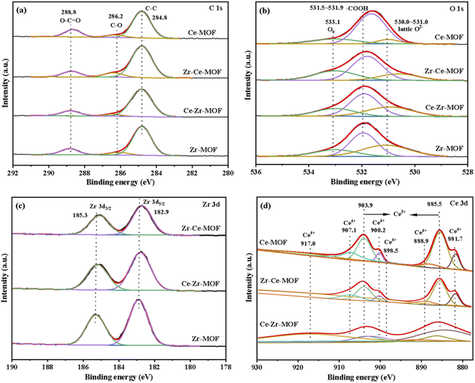
The surface chemical composition and electronic states of the four MOF materials were studied by XPS measurements, the obtained wide scan spectrum is shown in Fig. S2,† and the element composition information is summarized in Table 2. The corresponding high-resolution XPS spectra of C 1s, O 1s, Zr 3d and Ce 3d were fitted and demonstrated in Fig. 4(a)–(d), respectively. Fig. 4(a) shows that C 1s spectrum of all the four MOF materials exhibit three peaks, which are well recognized as being characteristics of C–C (284.8 eV), C–O (286.2 eV) and O–C![[double bond, length as m-dash]](https://www.rsc.org/images/entities/char_e001.gif) O (288.8 eV).50,51 Similarly, the O 1s region can be resolved into three peaks for all the catalysts [Fig. 4(b)]. The peak with the lower BE at 530–531.0 eV is associated with the lattice oxygen, while the peak with higher BE at 531.5–531.9 eV can be ascribed to the oxygen in BDC ligand, and the one at 533.1 eV representing the vacancy oxygen.52–54 It is worth noting that the position of the lattice oxygen in the samples is located at 531.9 eV for Zr-MOF, which shifts towards lower values (531.7 eV) after incorporating Ce into the framework. This result indicates that the Ce has been successfully incorporated into the Zr-MOF framework, leading to an altered electronic structure of the O atoms in the lattice due to different electron-withdrawing effect of Ce and Zr.
O (288.8 eV).50,51 Similarly, the O 1s region can be resolved into three peaks for all the catalysts [Fig. 4(b)]. The peak with the lower BE at 530–531.0 eV is associated with the lattice oxygen, while the peak with higher BE at 531.5–531.9 eV can be ascribed to the oxygen in BDC ligand, and the one at 533.1 eV representing the vacancy oxygen.52–54 It is worth noting that the position of the lattice oxygen in the samples is located at 531.9 eV for Zr-MOF, which shifts towards lower values (531.7 eV) after incorporating Ce into the framework. This result indicates that the Ce has been successfully incorporated into the Zr-MOF framework, leading to an altered electronic structure of the O atoms in the lattice due to different electron-withdrawing effect of Ce and Zr.
 | ||
| Fig. 4 The XPS spectra of (a) C 1s; (b) O 1s; (c) Zr 3d; (d) Ce 3d. | ||
In the high-resolution Zr 3d spectra [Fig. 4(c)], two peaks at around 182.9 eV and 185.3 eV were observed, which represents Zr 3d5/2 of the zirconium atoms in Zr6 clusters and Zr 3d3/2 of the zirconium atoms in missing-linker defects, respectively.30,50 Besides, with the introduction of Ce, the binding energies of Zr 3d shifted to lower energies [Fig. 4(c)], indicating the successful introduction of Ce into the material, which is consistent with the results from XRD. Furthermore, with the increasing content of Ce in the material (as shown in Table 2), more obvious shift was detected, which could be attributed to the varies electron withdrawing capability of Ce and Zr.
The Ce 3d spectrum could be deconvoluted into four pairs of spin-orbital doublet peaks (3d3/2 and 3d5/2) as shown in Fig. 4(d): 881.7 eV/900.2 eV, 885.5 eV/903.9 eV, 888.9 eV/907.1 eV and 898.5 eV/917.0 eV. The peaks at 881.7 eV/900.2 eV, 888.9 eV/907.1 eV and 898.5 eV/917.0 eV are assigned to Ce(IV) species, while the peaks at 885.5 eV/903.9 eV are attributed to Ce(III) species.55,56 These results reveal co-existence of Ce(III) species and Ce(IV) species on the surface of Ce-MOF, Zr–Ce-MOF and Ce–Zr-MOF, which leads to more defects in the material. Defects in UiO-66 is known to enhance Lewis acidic sites, hence, more Lewis acidic sites should be found in Zr–Ce-MOF and Ce–Zr-MOF. To verify this, the pyridine-IR analysis of the samples was investigated, and the result is shown in Fig. 6(c). Zr–Ce-MOF and Ce–Zr-MOF presented much higher peak than pure Zr-MOF and Ce-MOF at 1580 cm−1.
The authentic composition of these four MOF materials was also investigated by ICP-MS, and the metal loading was summarized in Table 2. Notably, the total metal mass fraction increased from 17.61 wt% to 20.85 wt%, wherein Zr content improved from 17.61 wt% to 19.62 wt% when Ce was doped into the Zr-MOF, indicating that Ce doping is conducive to generation of active sites. On the other hand, if Zr was added later, the bulk Ce decreased from 20.97 wt% to 1.16 wt%, while the content of Zr was as high as 23.85 wt%, suggesting a stronger coordination of Zr metal with the organic linker than Ce. Furthermore, higher surface Ce content on Zr–Ce-MOF than on Ce–Zr-MOF was detected, demonstrating the crucial role Ce played for the CO2 transformation reaction, which is consistent with previous reports.46,74
The preceding discussed XRD and XPS results gave a strong indication that the incorporation of Ce had been achieved. In order to ascertain if this had any effect on other properties of MOF materials, UV-Vis DRS analyses were conducted, as shown in Fig. 5(a). After incorporation of Ce into the Zr-MOF, the absorption edge of the composite displayed an obvious red-shift, from 341 nm in the UV region to 409 nm and 419 nm in the visible light region, indicating the composite begins to absorb visible light after introduction of Ce, which could be attributed to both the structure effect and the electronic effect.57,58 Especially, for the Ce-MOF, the absorption edge was approximately 450 nm [Fig. 5(a)]. In addition, the optical band gaps of the as-prepared materials were calculated using Kubelka–Munk (KM) method, and the results are demonstrated in Fig. 5(b).46,59,60 It can be clearly seen that with the increasing content of Ce in the MOF (Zr-MOF, Ce–Zr-MOF, Zr–Ce-MOF and Ce-MOF), the band gaps decrease (3.53 eV > 2.88 eV > 2.87 eV > 2.63 eV). Previous reports have shown that band gap changes indicates obvious changes in the amount of defects in the materials, especially the oxygen vacancy change.46,61 Thus, the results indicate that the substitution of Ce with Zr species leads to the formation of oxygen vacancy in the material through distorting the lattice structure.
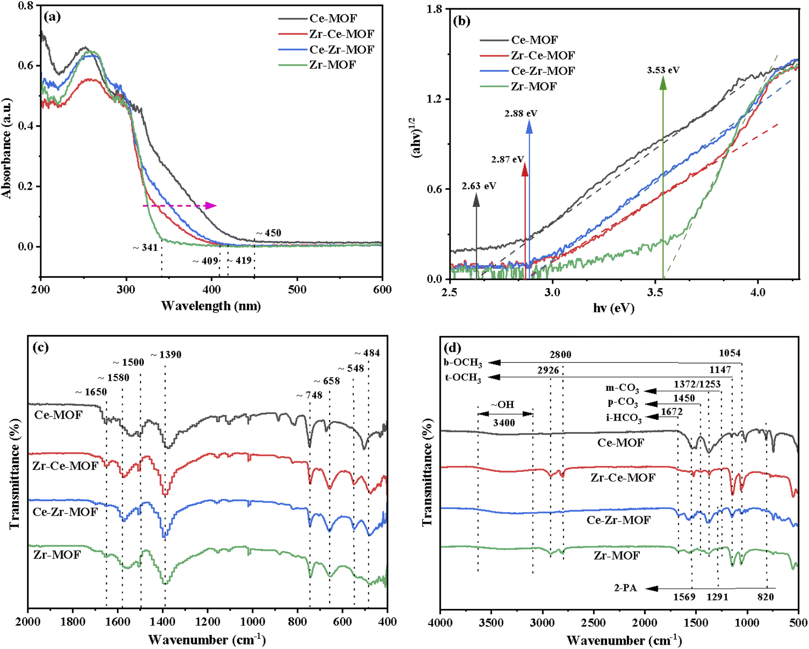 | ||
| Fig. 5 (a) UV-Vis diffuse absorbance spectra, (b) Tauc plots, (c) FT-IR spectra of fresh Zr/Ce-based MOF materials and (d) FT-IR spectra of used Zr/Ce-based MOF materials. | ||
To further investigate the chemical structure of the MOF materials, FT-IR spectra were obtained, as shown in Fig. 5(c). The characteristic peak of the CO stretching vibration from BDC in the frameworks at 1650 cm−1 are detected in all the four materials.39 However, the one for Ce-MOF is wider compared to that of the other three MOFs, indicating that the Ce ions in the material have been successfully coordinated with the CO of the BDC ligand.62 All materials show intense bands at 1580 cm−1 and 1390 cm−1, corresponding to the asymmetric and symmetric stretching vibrations of the –COOH from BDC ligand.63 The bands at 1500 cm−1 and 748 cm−1 could be assigned to the typical vibration of CC and the bending vibration of C–H on the benzene ring, respectively.52,54 For Zr-MOF, Zr–Ce-MOF and Ce–Zr-MOF, characteristic peaks for stretching vibration of Zr–Oμ3-O and Zr–Oμ3-OH bonds of the Zr6 cluster at 658 cm−1 and 484 cm−1 were detected, verifying again that Zr-MOF structures can be formed more easily when Ce and Zr co-existing during the preparation procedure.63 An obvious shift for the two peaks was observed for Ce-MOF, suggesting similar structure of Ce-MOF to that of Zr-MOF. In the low-frequency region, the band near 548 cm−1 is ascribed to Zr–O–C or Ce–O–C asymmetric stretching vibration.63
It is widely reported that acid–base properties are crucial to the CO2 conversion.64 As basic sites are required to activate the CO2 molecule, while acid–base pair sites are often reported to be mandatory for methanol activation (CH3O− and CH3+ formation). Acidity and basicity properties of the four samples were characterized by NH3-and CO2-TPD, as presented in Fig. 6(a) and (b), respectively. NH3-TPD profiles, as illustrated in Fig. 6(a), presented two broad peaks centered at about 120 °C and 270 °C for all the samples. However, the amount of acid sites (desorption peak area) was significantly affected by the introduction of Ce into Zr-MOF lattice. The amount of acid sites reached maximum for Zr–Ce-MOF. Moreover, strong acid sites with the desorption temperature over 400 °C were observed in Zr–Ce-MOF, demonstrating the influence of dopant Ce on the acidity of Zr-based MOF material.
 | ||
| Fig. 6 Temperature programmed desorption (TPD) of (a) NH3, (b) CO2 on the prepared MOF materials and (c) pyridine-IR results of MOF materials. | ||
Meanwhile, the CO2-TPD profiles are also shown in Fig. 6(b). CO2 desorption peaks in the regions of 100–350 °C were observed and could be ascribed to the desorption of different carbonate species (linear species, bidentate carbonate and monodentate carbonate). A distinguished sharp desorption peak at 180 °C was observed in the CO2-TPD of Zr–Ce-MOF, which can be assigned to the removal of bidentate carbonate species on the surface.46,65 The absence of this particular peak in the other three samples could explain the smaller catalytic activity of the three samples.
In addition, Py-IR experiments are performed to distinguish Lewis acidic sites (LAS) and Brønsted acidic sites (BAS) on Zr-based MOFs. As shown in Fig. 6(c), the bands at 1610, 1580 and 1440 cm−1 are ascribed to LAS with the label P-L, while the bands at 1655 and 1540 cm−1 are assigned to BAS with the label P-B.47,66 It is also observed that a combined additional band at 1504 cm−1 is attributed to the vibration of pyridine on both LAS and BAS acid sites with the label P-L+B presents on catalysts.66,67 The Py-IR results showed small bands of LAS at 1580 cm−1 on both Zr-MOF and Ce-MOF, but doping of Ce into the Zr-MOF significantly increased the intensity of the band. The LAS was reported to be important in the adsorption of CO2.46,68 Therefore, by doping Ce, varied catalytic activity can be derived for Zr-based MOFs.69,70
Overall, the catalytic activities of the MOF materials were not linearly dependent on the special surface areas, suggesting that other properties of the catalysts should be considered for the better activities of Zr–Ce-MOF. As reported previously, the catalytic activity of catalysts for CO2 conversion related to the surface area, crystallite size, acid–base properties as well as the surface ratio of Ce4+/Ce3+. However, based on the N2 adsorption–desorption, XRD and XPS results in the present study, there is no direct correlation between the crystallite size, surface area and surface proportion of Ce4+/Ce3+ and the activity of the MOF materials.
The acid–base properties of the MOF catalysts were also examined in this study, but the amounts of acidic and basic sites were not in obvious linear relationship with the yield of DMC. The amount of basic sites, which were in favor of CO2 adsorption and activation, has no direct relationship with the doping of Ce. However, the weak basic site is a key factor for the catalytic activity, which can form bidentate carbonate species on the surface with CO2. By inspection of Fig. 6(a), it could be seen that the more acid sites catalysts possessed, the better catalytic performance they displayed [Fig. 2(a)]. As shown by Fig. 6(c), the Lewis acid sites responsible for the adsorption and activation of OH group of alcohols is another key factor for the catalytic activity. Therefore, the improved acid–base properties might take major part of the responsibility for the better catalytic performance of Zr–Ce-MOF material.
Possible mechanism analysis of CO2 conversion
To understand the structure of adsorbed species and the nature of the active sites, FT-IR of the used MOF materials was then conducted, as shown in Fig. 5(d). Fig. 5(d) demonstrates that terminal methoxy (t-OCH3) and bridged methoxy (b-OCH3) were detected for all four materials, which are generated from CH3OH activation on catalysts. Similarly, monodentate carbonate (m-CO3), ionic bicarbonate (i-HCO3) and polydentate carbonate (p-CO3) were observed due to CO2 activation on catalysts.46,47 The emergence of the bands at 1569 cm−1 (νring), 1291 cm−1 (δC−N), and 820 cm−1 (γCO) are characteristic of 2-picolinamide anion (Py-CONH−), which is the surface intermediate in the hydrolysis of 2-cyanopyridine toward 2-PA.71 Dragos S. and co-workers reported that this specie hinders the formation of t-OCH3 species, leading to the deactivation of the catalyst over time.72
Integrated analysis of the IR result and the catalytic evaluation results showed that, the activation of methanol is crucial during the reaction, especially the generation of t-OCH3 species from LAS activation of methanol, which could be the limiting step of the reaction. Though more m-CO3 species was detected from Ce-MOF and Zr-based MOF, smaller TOF illustrates that the activation of CO2 is not the limiting step.
Based on the above analysis, we propose a possible reaction mechanism, as shown in Scheme 2. During the DMC formation process from methanol and CO2, methanol gets activated by Lewis acid sites to form b-OCH3 and t-OCH3, CO2 is activated on basic sites and reacted with the CH3O− species to generate m-CH3OCOO−. DMC is formed through the reaction of CH3OCOO− with another activated methanol, and the H atom from methanol activation then reacts with the surface OH group to form H2O.30,73,74
 | ||
| Scheme 2 Possible mechanism scheme for the catalytic CO2 conversion into DMC over Ce-doped MOF. | ||
Conclusions
In summary, a series of Zr/Ce microporous MOFs with UiO-66 architecture have been successfully synthesized, which displayed varies catalytic activity for CO2 conversion to DMC. The addition order of metals (Ce and Zr) affects the morphology significantly. The MOF with Ce adding first was observed to have the highest catalytic activity. Zr was found to have stronger coordination with the organic linker than Ce. Besides, it is demonstrated that the increase in the Lewis acid sites that adsorb and activate the OH group of alcohols leads to the improvement of the catalytic activity of Ce doped Zr-MOF. The enhanced terminal methoxy (t-OCH3) peak in IR spectra for Zr–Ce-MOF verified this, and the formation of terminal methoxy (t-OCH3) is observed to be the limiting step for this catalytic system.Abbreviations
| DMC | Dimethyl carbonate |
| 2-CY | 2-Cyanopyridine |
| 2-PA | 2-Picolinamide |
| P-2 | Methyl pyridine-2-carboximidate |
| P-C | Methyl picolinimidate |
Conflicts of interest
There are no conflicts to declare.Acknowledgements
The authors gratefully acknowledge Hongchao Wang from Yanshan University for N2 adsorption–desorption measurement. This work is supported by National Natural Science Foundation of Hebei Province (B2022203019), Chinese Overseas Returnees Funding from Hebei Province Department of Human Resources and Social Security (C20200368), Subsidy for Hebei Key Laboratory of Applied Chemistry after Operation Performance (22567616H), and fundings from Yanshan University (213000211 and BL8190120).References
- M. D. Burkart, N. Hazari, C. L. Tway and E. L. Zeitler, ACS Catal., 2019, 9, 7937–7956 CrossRef CAS.
- C. A. Trickett, A. Helal, B. A. Al-Maythalony, Z. H. Yamani, K. E. Cordova and O. M. Yaghi, Nat. Rev. Mater., 2017, 2, 1–16 CrossRef.
- A. Liu, M. Gao, X. Ren, F. Meng, Y. Yang, L. Gao, Q. Yang and T. Ma, J. Mater. Chem. A, 2020, 8, 3541–3562 RSC.
- A. Rafiee, K. Rajab Khalilpour, D. Milani and M. Panahi, J. Environ. Chem. Eng., 2018, 6, 5771–5794 CrossRef CAS.
- J. Artz, T. E. Müller, K. Thenert, J. Kleinekorte, R. Meys, A. Sternberg, A. Bardow and W. Leitner, Chem. Rev., 2018, 118, 434–504 CrossRef CAS.
- T. Zheng, K. Jiang and H. Wang, Adv. Mater., 2018, 30, 1802066 CrossRef.
- K. Larmier, W. Liao, S. Tada, E. Lam, R. Verel, A. Bansode, A. Urakawa, A. Comas-Vives and C. Copéret, Angew. Chem., Int. Ed., 2017, 56, 2318–2323 CrossRef CAS.
- T. Chang, M. Tamura, Y. Nakagawa, N. Fukaya, J. Choi, T. Mishima, S. Matsumoto, S. Hamura and K. Tomishige, Green Chem., 2020, 22, 7321–7327 RSC.
- T. Wang, Y. Ma, J. Jiang, X. Zhu, B. Fan, G. Yu, N. Li, S. Wang, T. Ren, L. Wang and J. Zhang, J. Mol. Liq., 2019, 293, 111479 CrossRef CAS.
- Y. Chen, Q. Tang, Z. Ye, Y. Li, Y. Yang, H. Pu and G. Li, New J. Chem., 2020, 44, 12522–12530 RSC.
- S. Huang, B. Yan, S. Wang and X. Ma, Chem. Soc. Rev., 2015, 44, 3079–3116 RSC.
- A. H. Tamboli, A. A. Chaugule and H. Kim, Chem. Eng. J., 2017, 323, 530–544 CrossRef CAS.
- M. Zhang, Y. Xu, B. L. Williams, M. Xiao, S. Wang, D. Han, L. Sun and Y. Meng, J. Cleaner Prod., 2021, 279, 123344 CrossRef CAS.
- M. Honda, M. Tamura, Y. Nakagawa, K. Nakao, K. Suzuki and K. Tomishige, J. Catal., 2014, 318, 95–107 CrossRef CAS.
- B. A. V. Santos, V. M. T. M. Silva, J. M. Loureiro and A. E. Rodrigues, ChemBioEng Rev., 2014, 1, 214–229 CrossRef CAS.
- A. A. Chaugule, H. A. Bandhal, A. H. Tamboli, W. Chung and H. Kim, Catal. Commun., 2016, 75, 87–91 CrossRef CAS.
- T. Zhao, X. Hu, D. Wu, R. Li, G. Yang and Y. Wu, ChemSusChem, 2017, 10, 2046–2052 CrossRef CAS.
- C. Liu, S. Zhang, B. Cai and Z. Jin, Chin. J. Catal., 2015, 36, 1136–1141 CrossRef CAS.
- Q. Yang, H. Wang, X. Ding, X. Yang and Y. Wang, Res. Chem. Intermed., 2015, 41, 4101–4111 CrossRef CAS.
- H. J. Lee, S. Park, I. K. Song and J. C. Jung, Catal. Lett., 2011, 141, 531–537 CrossRef CAS.
- A. A. Marciniak, O. C. Alves, L. G. Appel and C. J. A. Mota, J. Catal., 2019, 371, 88–95 CrossRef CAS.
- H. Chen, S. Wang, M. Xiao, D. Han, Y. Lu and Y. Meng, Chin. J. Chem. Eng., 2012, 20, 906–913 CrossRef CAS.
- C. L. Chiang, K. S. Lin and S. Yu, Res. Chem. Intermed., 2018, 44, 3797–3811 CrossRef CAS.
- A. Poungsombate, T. Imyen, P. Dittanet, B. Embley and P. Kongkachuichay, J. Taiwan Inst. Chem. Eng., 2017, 80, 16–24 CrossRef CAS.
- K. Xuan, Y. Pu, F. Li, J. Luo, N. Zhao and F. Xiao, Chin. J. Catal., 2019, 40, 553–566 CrossRef CAS.
- X. Deng, L. Yang, H. Huang, Y. Yang, S. Feng, M. Zeng, Q. Li and D. Xu, Small, 2019, 15, 1902287 CrossRef.
- H. Wang, Q. Zhu, R. Zou and Q. Xu, Chem, 2017, 2, 52–80 CAS.
- H. He, J. A. Perman, G. Zhu and S. Ma, Small, 2016, 12, 6309–6324 CrossRef CAS.
- A. Yurduşen and Y. Yürüm, Ind. Eng. Chem. Res., 2019, 58, 14058–14072 CrossRef.
- K. Xuan, Y. Pu, F. Li, A. Li, J. Luo, L. Li, F. Wang, N. Zhao and F. Xiao, J. CO2 Util., 2018, 27, 272–282 CrossRef CAS.
- S. Biswas and P. Van Der Voort, Eur. J. Inorg. Chem., 2013, 2013, 2154–2160 CrossRef CAS.
- M. Stawowy, M. Róziewicz, E. Szczepańska, J. Silvestre-Albero, M. Zawadzki, M. Musioł, R. Łuzny, J. Kaczmarczyk, J. Trawczyński and A. Łamacz, Catalysts, 2019, 9, 309 CrossRef.
- V. R. Bakuru, S. R. Churipard, S. P. Maradur and S. B. Kalidindi, Dalton Trans., 2019, 48, 843–847 RSC.
- S. Rojas-Buzo, P. Concepción, J. L. Olloqui-Sariego, M. Moliner and A. Corma, ACS Appl. Mater. Interfaces, 2021, 13, 31021–31030 CrossRef CAS PubMed.
- F. Nouar, M. I. Breeze, B. C. Campo, A. Vimont, G. Clet, M. Daturi, T. Devic, R. I. Walton and C. Serre, Chem. Commun., 2015, 51, 14458–14461 RSC.
- J. H. Cavka, S. Jakobsen, U. Olsbye, N. Guillou, C. Lamberti, S. Bordiga and K. P. Lillerud, J. Am. Chem. Soc., 2008, 130, 13850–13851 CrossRef PubMed.
- B. Wang, Q. Yang, C. Guo, Y. Sun, L. Xie and J. Li, ACS Appl. Mater. Interfaces, 2017, 9, 10286–10295 CrossRef CAS.
- M. Lammert, C. Glißmann, H. Reinsch and N. Stock, Cryst. Growth Des., 2017, 17, 1125–1131 CrossRef CAS.
- M. Lammert, M. T. Wharmby, S. Smolders, B. Bueken, A. Lieb, K. A. Lomachenko, D. D. Vos and N. Stock, Chem. Commun., 2015, 51, 12578–12581 RSC.
- G. C. Shearer, S. Chavan, S. Bordiga, S. Svelle, U. Olsbye and K. P. Lillerud, Chem. Mater., 2016, 28, 3749–3761 CrossRef CAS.
- R. M. Rego, G. Sriram, K. V. Ajeya, H. Jung, M. D. Kurkuri and M. Kigga, J. Hazard. Mater., 2021, 416, 125941 CrossRef CAS PubMed.
- G. C. Shearer, S. Chavan, J. Ethiraj, J. G. Vitillo, S. Svelle, U. Olsbye, C. Lamberti, S. Bordiga and K. P. Lillerud, Chem. Mater., 2014, 26, 4068–4071 CrossRef CAS.
- M. Thommes, K. Kaneko, A. V. Neimark, J. P. Olivier, F. Rodriguez-Reinoso, J. Rouquerol and K. S. W. Sing, Pure Appl. Chem., 2015, 87, 1051–1069 CrossRef CAS.
- H. Ohno, M. Ikhlayel, M. Tamura, K. Nakao, K. Suzuki, K. Morita, Y. Kato, K. Tomishige and Y. Fukushima, Green Chem., 2021, 23, 457–469 RSC.
- D. J. Faria, L. Moreira Dos Santos, F. L. Bernard, I. Selbacch Pinto, M. A. Carmona Da Motta Resende and S. Einloft, RSC Adv., 2020, 10, 34895–34902 RSC.
- B. Liu, C. Li, G. Zhang, X. Yao, S. S. C. Chuang and Z. Li, ACS Catal., 2018, 8, 10446–10456 CrossRef CAS.
- X. Wang, J. Zhao, Y. Li, S. Huang, J. An, R. Shi, Y. Pei, Z. Li and J. Ren, Chem. Eng. Sci., 2021, 229, 116018 CrossRef CAS.
- A. A. Pawar, D. Lee, W. Chung and H. Kim, Chem. Eng. J., 2020, 395, 124970 CrossRef CAS.
- S. Kumar, M. B. Gawande, I. Medřík, M. Petr, O. Tomanec, V. Kupka, R. S. Varma and R. Zbořil, Green Chem., 2020, 22, 5619–5627 RSC.
- Y. Wu, X. Chen, X. Luo, M. Yang, C. Hou and D. Huo, Anal. Chim. Acta, 2021, 1183, 339000 CrossRef CAS.
- J. He, Y. Xu, W. Wang, B. Hu, Z. Wang, X. Yang, Y. Wang and L. Yang, Chem. Eng. J., 2020, 379, 122431 CrossRef CAS.
- Y. Yang, D. Zhang, W. Ji, F. Bi, L. Song and X. Zhang, J. Colloid Interface Sci., 2022, 606, 1811–1822 CrossRef CAS PubMed.
- D. Phan, V. N. Le, J. Kim and E. Y. Lee, Fuel Process. Technol., 2021, 224, 107001 CrossRef CAS.
- S. Li, Y. Jin, Z. Hu, Y. Liu, S. Wu, Y. Wang and G. Wang, J. Radioanal. Nucl. Chem., 2021, 330, 857–869 CrossRef CAS.
- B. Peng, J. Cui, Y. Wang, J. Liu, H. Zheng, L. Jin, X. Zhang, Y. Zhang and Y. Wu, Nanoscale, 2018, 10, 1939–1945 RSC.
- Y. Xiong, S. Chen, F. Ye, L. Su, C. Zhang, S. Shen and S. Zhao, Chem. Commun., 2015, 51, 4635–4638 RSC.
- M. M. Khan, S. A. Ansari, M. I. Amal, J. Lee and M. H. Cho, Nanoscale, 2013, 5, 4427 RSC.
- M. M. Khan, S. A. Ansari, D. Pradhan, M. O. Ansari, D. H. Han, J. Lee and M. H. Cho, J. Mater. Chem. A, 2014, 2, 637–644 RSC.
- Y. Wang, B. Li, C. Zhang, L. Cui, S. Kang, X. Li and L. Zhou, Appl. Catal., B, 2013, 130–131, 277–284 CrossRef CAS.
- N. Wetchakun, S. Chaiwichain, B. Inceesungvorn, K. Pingmuang, S. Phanichphant, A. I. Minett and J. Chen, ACS Appl. Mater. Interfaces, 2012, 4, 3718–3723 CrossRef CAS.
- X. Pan, M. Yang, X. Fu, N. Zhang and Y. Xu, Nanoscale, 2013, 5, 3601 RSC.
- X. Dong, Y. Lin, Y. Ma and L. Zhao, RSC Adv., 2019, 9, 27674–27683 RSC.
- Y. L. Wang, S. Zhang, Y. F. Zhao, J. Bedia, J. J. Rodriguez and C. Belver, J. Environ. Chem. Eng., 2021, 9, 106087 CrossRef CAS.
- K. Tomishige, Y. Gu, T. Chang, M. Tamura and Y. Nakagawa, Mater. Today Sustain., 2020, 9, 100035 CrossRef.
- C. Xin, M. Hu, K. Wang and X. Wang, Langmuir, 2017, 33, 6667–6676 CrossRef CAS PubMed.
- S. Pyen, E. Hong, M. Shin, Y. Suh and C. Shin, Mol. Catal., 2018, 448, 71–77 CrossRef CAS.
- M. Tamura, K. Shimizu and A. Satsuma, Appl. Catal., A, 2012, 433–434, 135–145 CrossRef CAS.
- Y. Chen, Y. Li, W. Chen, W. W. Xu, Z. Han, A. Waheed, Z. Ye, G. Li and A. Baiker, Nano Res., 2022, 15, 1366–1374 CrossRef CAS.
- Z. Fu, Y. Zhong, Y. Yu, L. Long, M. Xiao, D. Han, S. Wang and Y. Meng, ACS Omega, 2018, 3, 198–207 CrossRef CAS PubMed.
- A. Li, Y. Pu, F. Li, J. Luo, N. Zhao and F. Xiao, J. CO2 Util., 2017, 19, 33–39 CrossRef CAS.
- D. Stoian, A. Bansode, F. Medina and A. Urakawa, Catal. Today, 2017, 283, 2–10 CrossRef CAS.
- D. Stoian, F. Medina and A. Urakawa, ACS Catal., 2018, 8, 3181–3193 CrossRef CAS.
- W. Kuan, W. Yu, F. Tu, C. Chung, Y. Chang, M. M. Lin, T. Yu and L. Chen, Chem. Eng. J., 2022, 430, 132941 CrossRef CAS.
- A. H. Tamboli, A. A. Chaugule, S. W. Gosavi and H. Kim, Fuel, 2018, 216, 245–254 CrossRef CAS.
Footnote |
| † Electronic supplementary information (ESI) available. See https://doi.org/10.1039/d2ra02680e |
| This journal is © The Royal Society of Chemistry 2022 |