
 Open Access Article
 This Open Access Article is licensed under a Creative Commons Attribution-Non Commercial 3.0 Unported Licence
Superior quality chemically reduced graphene oxide for high performance EMI shielding materials
Ramy Sadek a,
Mohammad S. Sharawib,
Charles Duboisa,
Hesham Tantawyc and
Jamal Chaouki*a
a,
Mohammad S. Sharawib,
Charles Duboisa,
Hesham Tantawyc and
Jamal Chaouki*a
aChemical Engineering Department, Polytechnique Montréal, Montréal, H3C 3A7, Canada. E-mail: jamal.chaouki@polymtl.ca; Tel: +1 514 340 4711, ext. 4034
bPoly-Grames Research Center, Electrical Engineering Department, Polytechnique Montréal, Montréal, QC H3C 3A7, Canada
cChemical Engineering Department, Military Technical College, Cairo, Egypt
First published on 12th August 2022
Abstract
The chemical reduction process of graphene oxide combined with a mild and controllable thermal treatment under vacuum at 200 °C for 4 hours provided a cost-effective, scalable, and high-yield route for Reduced Graphene Oxide (RGO) industrial production and became a potential candidate for producing electromagnetic interference (EMI) shielding. We investigated graphite, and RGO using L-ascorbic acid and Sodium borohydride before and after thermal treatment by carefully evaluating the chemical and morphological structures. The thermally treated L-ascorbic Acid reduction route (TCRGOL) conductivity was 2.14 × 10³ S m−1 and total shielding efficiency (SET) based on mass loadings per area of shielding was 94 dB with about one-tenth less graphite weight and surpassing other graphene reduction mechanisms in the frequency range of 8.2–12.4 GHz, i.e., X-band, at room temperature while being tested using the waveguide line technique. The developed treatment represents valuable progress in the path to chemical reduction using a safe reducing agent and offering superior quality RGO rarely achieved with the top-down technique, providing a high EMI shielding performance.
1. Introduction
The fast dissemination of portable communication devices, such as satellite communication, automobile collision prevention radar, accident surveillance of a railroad and millimetre-wave wireless local area network (mmw LAN), has caused a massive increase in electromagnetic interference (EMI) and its negative influence on living creatures (e.g., symptoms of insomnia, headaches, heart attack, blood pressure, brain tumor and joint pain)1,2 and interrupted the regular functioning of sensitive electronic devices (e.g., medical health recovery equipment and airplane flight cabin equipment).3,4 Consequently, researchers are trying to find reliable solutions by developing electromagnetic interference (EMI) shielding materials that can attenuate the electromagnetic waves to the highest degree possible by either reflection, absorption, or both, starting with traditional EMI shielding materials (e.g., sheet metals, metallic screen, and metallic foam) to advanced EMI shielding materials, such as conductive polymers, carbon nanotubes (CNTs), and graphene, which had been developed to overcome the drawbacks of traditional EMI shields by providing lightweight, flexible, corrosion resistant, low cost and durable shields.5,6The shielding effectiveness (SE) of a material is expressed in decibels (dB) and can be categorized as poor for SE ≤ 10 dB, acceptable between 10 to 30 dB and high when it exceeds 30 dB since the adequate range for industrial and commercial applications is around 20 dB.7
Since its freestanding isolation in 2004 by Geim and Novoselov,8 graphene attracted scientists' interest as a shield agent with the advantage of its high electrical conductivity and excellent thermal stability. Therefore, many techniques had been developed to produce single-layer graphene and reduced graphene oxide (RGO).9 The RGO is an attractive alternative to single-layer graphene but covalently functionalized with oxygen-containing groups (e.g., hydroxyl, carbonyl), which may be regulated via chemical engineering depending on the required application.10,11 It can be easily prepared with a high yield through the top-down chemical synthesis technique, starting with graphite oxidation, then exfoliation, followed by reduction, which is considered a convenient route for large-scale RGO production. Remarkably, Marcano et al. reported a valuable development in Hummers' method for graphene oxide (GO) preparation known as the improved Hummers' method (IGO).12 The GO has low conductivity due to the oxidation/exfoliation processes due to the defects in its structure. Therefore, different reduction protocols, such as chemical (CRGO or RGO), thermal (TRGO), electrochemical (ERGO), and hydrothermal (HTRGO), are applied individually or in combination to regulate the GO structure and produce the reduced graphene oxide. These techniques enhance the RGO conductive properties and provide diverse RGO qualities with uncommon results for the same application.13–15 This work focuses on the chemical and thermal reduction protocols with a high yield and scalability advantage including the ability to fine-tune the amount of oxygen by regulating the experiment conditions during the oxidation and reduction process.16,17
The chemical reduction techniques are commonly used for RGO production by applying several reducing agents, such as hydrazine,18 sodium borohydride,19,20 L-ascorbic acid.21,22, etc. Different reductants lead to different RGO structures altering their properties over several applications.23,24 Hydrazine (N2H4) was the first reducing agent used to produce RGO at low temperature, but its toxicity and potential to cause explosions have limited its use for mass production,25,26 while sodium borohydride (NaBH4), the most used effective reducing agent, was developed by Gao et al. through a simple and effective two-step reduction process by deoxygenation through NaBH4 followed by dehydration with concentrated sulfuric acid.19 Still, the release of flammable gases and the possibility of spontaneous ignition, due to the evolution of hydrogen gas during preparation, require a lot of care and safety awareness during mass production.9 The L-ascorbic acid, also known as vitamin C, motivated Zhang et al. to deploy it as a reducing agent to have the advantage of its antioxidant property, high chemical stability in solvents, and to avoid using hazardous reductants, but its mild reductive ability made it less attractive in comparison with other reducing agents for EMI shielding applications.21,22
Thermal reduction methods are used as an effective alternative route, usually to reduce the GO directly to produce the thermally reduced graphene oxide (TRGO) and its quality depends on the thermal treatment conditions, which require high temperatures up to 2000 °C under certain environments (e.g., argon, hydrogen) that make it critical and sometimes crucial to the product quality.27,28 Additionally, the GO is hydrophilic and its separation from the aqueous medium is a challenging task since any treatment other than freeze-drying causes uncontrolled partial reduction, which will compromise the final quality and the required production repeatability when applying the thermal reduction.29
This study focuses on the development of the chemical reduction approach where a stable RGO structure is offered and easily separated followed by thermal treatment at 200 °C under vacuum for 4 hours to develop a high quality and repeatable reduced graphene oxide while clarifying the tolerance of the treatment based on the different types of employed reductants (i.e., L-ascorbic acid and NaBH4) depending on their reduction mechanisms. The chemical and morphological structures were evaluated via transmission electron microscopy (TEM), scanning electron microscope (SEM), X-ray diffraction (XRD), thermogravimetric analysis (TGA), Fourier transform-infrared (FTIR) spectra, and RAMAN spectroscopy. In addition, the electrical conductivity and EMI shielding effectiveness were assessed through the 4-point probe method and a vector network analyzer (VNA), respectively. It also provides a step forward for the future development of top-down methods to achieve cheap, feasible, high quality, lightweight EMI shielding materials in several applications, such as coatings, films, sheets, and paints.
2. Materials and preparation methods
2.1 Materials
Graphite powders were used as the starting material without any pre-treatment, sulphuric acid (H2SO4, ACS reagent, 95.0–98.0%), phosphoric acid solution (H3PO4, 85 wt%), hydrochloric acid (HCl, ACS reagent, 37%), CS reagent L-ascorbic acid, ≥99%, sodium borohydride powder, ≥98.0%, and ACS reagent sodium carbonate powder, ≥99.5% were purchased from Sigma-Aldrich. Hydrogen peroxide (H2O2, ACS reagent, 30%) and ACS potassium permanganate (KMnO4) were purchased from VWR for the GO preparation. Acetone, >99.5%, and ACS grade reagent alcohol 94.0–96.0% were purchased from Fisher Scientific and used for washing processes.2.2 Synthesis of GO
Improved Hummers' method was implemented to synthesize the graphene oxide from the graphite powder.12 An amount of 2 g graphite was blended in a 500 ml beaker that contains 240 ml sulfuric acid (H2SO4) and 26 ml phosphoric acid (H3PO4). Then, 12 g potassium permanganate (KMnO4) was added slowly in portions while stirring to avoid particle coagulation and heat accumulation and to ensure a thorough dispersion. The mixture was left to cool down and then agitated for 2–3 days until the formation of a viscous product. The mixture was added in portions to 3 L of distilled water (DW) while stirring at 400 rpm with a magnetic stirrer for 1 hour. Afterward, 10% hydrogen peroxide (H2O2) was prepared and added drop by drop through a titration funnel until the solution color turned a yellowish-orange. The mixture was stirred for 20 min. GO particles were washed by decantation 3 times with 15% hydrochloric acid (HCl), to minimize the impurities and prepare the GO suspension for the chemical reduction process. The preparation procedure, starting from graphite and going through oxidation and exfoliation, known as the improved Hummer's method, passes through some important visual changes reflecting the progress of the reaction, as shown in Fig. 1 (see caption for the identification of steps).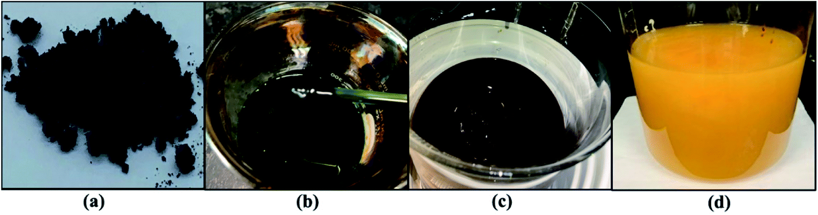 | ||
| Fig. 1 Graphene oxide reaction process: (a) graphite sample, (b) oxidation process, (c) graphene oxide exfoliation, (d) GO. | ||
2.3 Synthesis of RGO
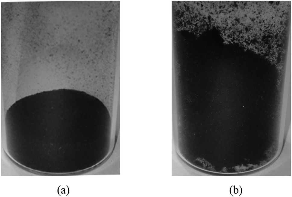 | ||
| Fig. 2 Visual inspection of: (a) RGOL and (b) TCRGOL. | ||
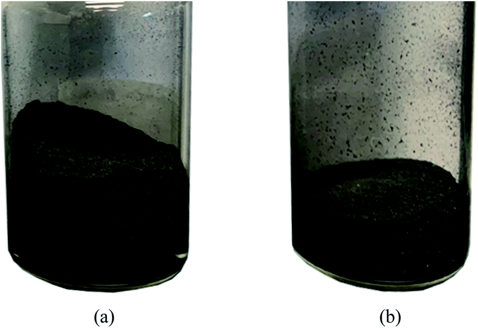 | ||
| Fig. 3 Visual inspection of: (a) RGOB and (b) TCRGOB. | ||
3. Characterization methods
3.1 Morphological
3.2 Crystallinity: XRD
A Bruker D8 Advance X-ray diffractometer equipped with a LYNXEYE linear position-sensitive detector (Bruker AXS, Madison, WI) was employed to record the samples' XRD patterns. The data collection was from 3 to 60° in a range of 2θ with an increase of 0.02° per step and the scanning rate was 0.2° s−1. The Cu-Kα source X-ray wavelength (λ = 0.15418 nm) was operated at a tube voltage of 40 kV and a current of 40 mA in the diffractometer. Powder samples were placed in a thin layer on a zero-background silicon crystal plate supported on a cup.3.3 Thermal stability
The thermogravimetric analysis (TGA) of 5 mg was carried out using TA Instruments Q-50 starting from room temperature to 800 °C with a heat rate of 5° min−1. Nitrogen gas flow was maintained at 20 ml min−1 in the reaction chamber as well as a similar flow to purge the balance chamber.303.4 Electrical conductivity
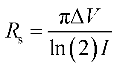
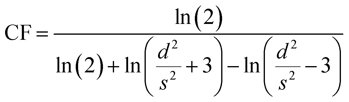
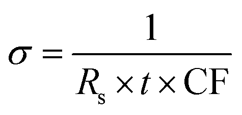
The Magnetron m-800 equipment equipped with a Jandel four-point probe (probe spacing 1 mm and 1013 ohms resistance between needles at 500 volts) connected to an Agilent B2902A voltage–current source measuring unit was used to measure the sample's electrical conductivity as pressed pellets at room temperature. Circular-shaped pellets with dimensions of 20 mm in diameter and 0.27 ± 0.09 mm in thickness were prepared by pressing 0.142 ± 0.037 g samples at 150 MPa for 1 min. Three pellets were produced for each sample for a total of 15 pellets and measured five times to obtain the mean values of the conductivity.Current–voltage (I–V) measurements were carried out via Agilent B2902A over a voltage range of 0.01 to 0.07 V with 0.01 V stepwise. The I–V values were collected, then the sheet resistance (Rs) was calculated as in eqn (1). Also, the shape correction factor (CF) was illustrated in eqn (2) to evaluate the conductivity (σ) in [S m−1] of the studied samples following eqn (3).31,32
 | (1) |
 | (2) |
 | (3) |
3.5 Chemical analysis
Raman spectra were performed on dry powder samples using the WITec RAMAN spectrometer equipped with an alpha300 access microscope with a motorized stage, which moves in planar (x–y-direction), CCD detector, and 1800 grooves per mm for optical grating.
The laser source was a 532 nm UHTS300S_GREEN_NIR laser with 18 mW of power. The sample spectra were obtained at 532.143 nm excitation wavelength with 100X: Zeiss EC Epiplan-Neofluar, WD0.31 mm, NA 0.9 DIC. The integration time was 10 seconds, and the number of accumulations was 20. Measurements were done in 5 different spots for each evaluated sample considering the most relevant spectrum. It is worth mentioning that the 2D band can be significantly different with different excitation laser frequencies. Accordingly, the same excitation laser frequency was applied for measurements and characterization.
3.6 Electromagnetic shielding
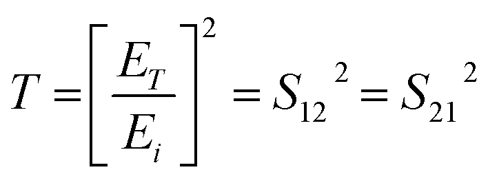
The Keysight PNA-X Network Analyzer Model N5247B was used to evaluate the electromagnetic shielding measurements over the X-band from 8.2 to 12.4 GHz at the Poly-Grames research center. The scattering S-parameters reflection and transmission parameters (e.g., S11, S12, S21, and S22) were gathered through two open-ended waveguides (WR-90) connected with a sample holder filled with samples as shown in Fig. 4(a), where the dimension of the cross-section of the waveguide and the sample holder was 22.86 mm × 10.16 mm. For measurement accuracy, the network analyzer was calibrated by the Thru-Reflect-Line (TRL) calibration.33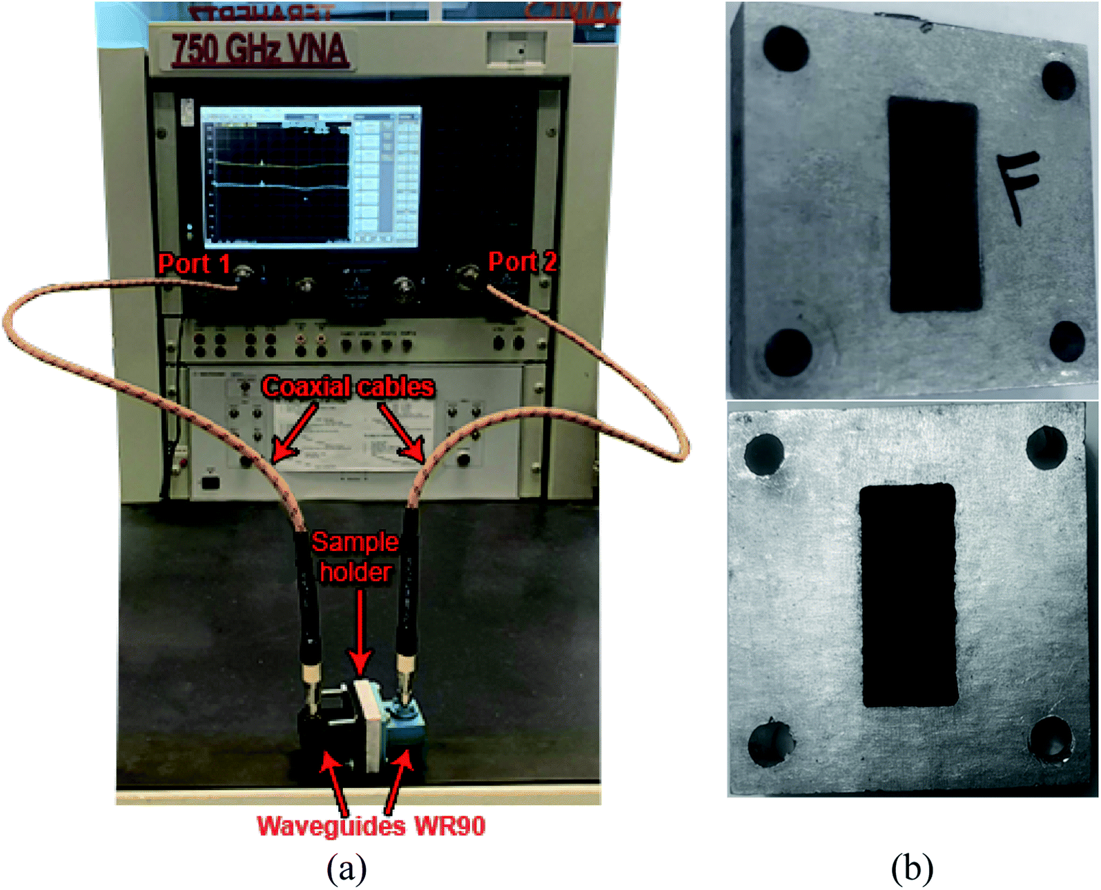 | ||
| Fig. 4 EMI waveguide: (a) measurement setup and (b) front and back views of filled sample holders. | ||
The sample holders were filled with graphite and different RGOs as a compressed powder with different known quantities with thicknesses ranging from 1 to 3 mm using a Carver hydraulic press under 25 MPa for 1 min. The sample formation as a compressed powder inside the WR-90 waveguide sample holder is shown in Fig. 4(b). The average transmission losses (TL) in decibels (dB) for each sample were evaluated regarding the concentration per unit area (g cm−2). This representation has been adopted to provide an explicit model for shielding efficiency evaluation and the loaded materials, considering the proportionality between the SE, the shield thickness, and the density factor per unit area out of the width.34
The reflection, absorption, and total shielding efficiencies (i.e., SER, SEA, and SET) were calculated over the X-band frequency as expressed in eqn (4)–(9).35
 | (4) |
 | (5) |
 | (6) |
SER = 10![[thin space (1/6-em)]](https://www.rsc.org/images/entities/char_2009.gif) log(1 − R) log(1 − R)
| (7) |
 | (8) |
 | (9) |
4. Results and discussion
4.1 Morphology
Graphite and different RGO morphologies were studied by SEM and TEM micrography as illustrated in Fig. 5. Fig. 5(a) is a typical graphite SEM image where the particles have a coarse and consistent shape. The image of RGOL in Fig. 5(b) shows some wrinkles reflecting a degree of sheet exfoliation due to the chemical treatment while after the thermal treatment the TCRGOL reaches a higher degree of exfoliation with a smoother and fluffy surface as shown in Fig. 5(c). The RGOB and TCRGOB both have nearly the same morphological appearance with a higher degree of exfoliation in comparison to RGOL, which has a crumpled or wavy silk-like structure elucidated in Fig. 5(d) and (e), respectively.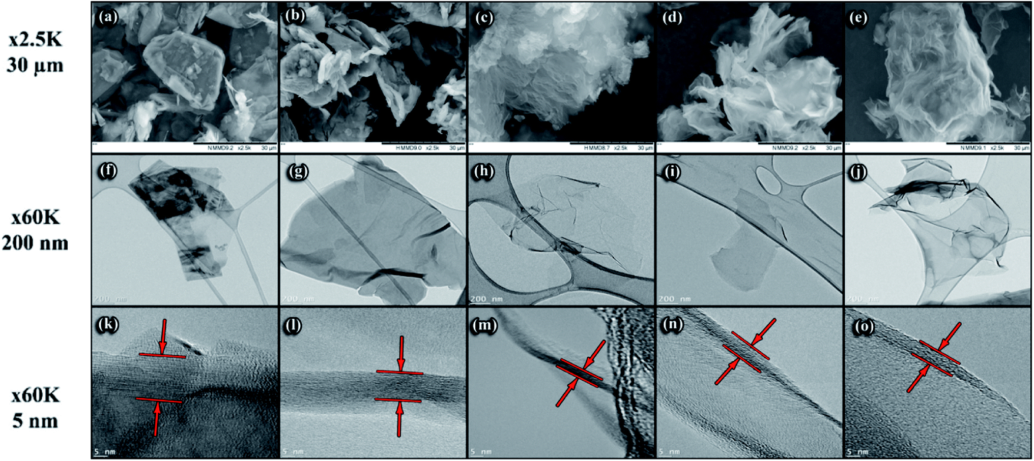 | ||
| Fig. 5 SEM and TEM images of graphite and different RGOs. SEM images [30 μm] (first raw): (a) graphite, (b) RGOL, (c) TCRGOL, (d) RGOB, and (e) TCRGOB. TEM images [200 nm] (second raw): (f) graphite, (g) RGOL, (h) TCRGOL, (i) RGOB, and (j) TCRGOB. TEM images [5 nm] for layer thickness identified with red arrows (third raw): (k) graphite, (l) RGOL, (m) TCRGOL, (n) RGOB, and (o) TCRGOB. | ||
Additionally, the TEM provides images where the sample flakes become detectable. The graphite sheets (Fig. 5(f)) show a coherent particle shape, which becomes a wrinkled flake with a smooth surface after the chemical exfoliation for RGOL (Fig. 5(g)) and RGOB (Fig. 5(i)), as well the thermally treated samples of TCRGOL and TCRGOB in Fig. 5(h) and (j), respectively. At the 60k magnification level, the major difference between the reduced forms of graphene is the transparency of the sheet surface, which correlates with the thickness of the particle. So, the TCRGOL sheet was more transparent than other samples suggesting the fewest number of layers.
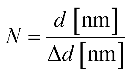
At the 5 nm scale, the graphene sheets can be observed by looking for where the graphene sheet folds over itself at the edges as the planes become parallel to the electron beam causing the appearance of fringes, which are visible dark lines forming the sheet thickness marked by the red arrows on Fig. 5(k)–(o). The lattice fringes (d-spacing or Δd) represent the interplanar spacing (dhkl). The sum of all fringes represents the whole layer thickness indicated by the two red lines (d). All dimensions were measured using the software ImageJ V1.53k.36 Consequently, it is possible to detect the number of layers (N) by implementing the correlation between the observed thickness and the interlayer spacing illustrated by eqn (10).37
 | (10) |
Table 1 summarizes the data evaluated from the TEM analysis. The thickness was recorded by averaging 5 different spots for each sample and the interlayer spacing was calculated from Bragg's law using X-ray diffraction (XRD) results for accurate d-spacing values (Table 2). Also, the carbon to oxygen ratio was evaluated to detect the restoration of the graphitic structure in comparison to graphite.38,39 By applying eqn (10), the number of layers was estimated where the RGOL had 25 layers and RGOB was 14 layers. A high impact was observed after the thermal treatment following the L-ascorbic acid reduction route (i.e., TCRGOL) providing 7 layers, while the sodium borohydride approach (i.e., TCRGOB) was 13 layers. Graphite is known for its high number of stacked layers, which are bonded together by van der Waals forces and the TEM shows one stack of graphite particles. The high deviation value of the tested thickness increases the uncertainty of delivering its number of layers and makes it difficult to estimate the accurate number of layers. It has, however, a high number of not less than 50 layers.
| Sample | Layer thickness [nm] | Number of layers | C/O ratio |
|---|---|---|---|
| Graphite | 15.5 ± 3 | >50 | 0.98 |
| RGOL | 9.5 ± 0.3 | ∼25 | 0.76 |
| TCRGOL | 2.3 ± 0.2 | ∼7 | 0.88 |
| RGOB | 4.9 ± 0.1 | ∼14 | 0.86 |
| TCRGOB | 4.5 ± 0.2 | ∼13 | 0.82 |
| Sample | Crystallinity index (%) | d-Spacing (nm) |
|---|---|---|
| Graphite | 81 | 0.334 @ (002) peak |
| Graphene oxide | 66 | 0.873 @ (001) peak |
| RGOL | 50 | 0.369 @ (002) peak |
| TCRGOL | 30 | 0.368 @ (002) peak |
| RGOB | 48 | 0.371 @ (002) peak |
| TCRGOB | 53 | 0.359 @ (002) peak |
The carbon to oxygen ratio (C/O ratio) was determined by applying energy-dispersive X-ray spectroscopy (EDS), correlating the average area under the curve of detected carbon and oxygen content of the material on a copper grid zone (three different spots for each sample) to estimate the expected restoration of graphene layers. It was found that the TCRGOL scores 89.5% of the starting material graphite surpassing the other reduction studied protocols. It is obvious that the proposed reduction protocol had a great influence on the final desired RGO structure, and the excess thermal treatment procedure should be considered with care as it may alter the final product based on the employed reducing agent.
4.2 XRD characterization
Fig. 6(a) confirms the successful transformation of graphite to GO after treatment with the improved Hummers' method. The graphite characteristic diffraction peak (002), located at 2θ = 26°, is transformed to the graphene oxide peak at 001 with an angle of 2θ = 10°.40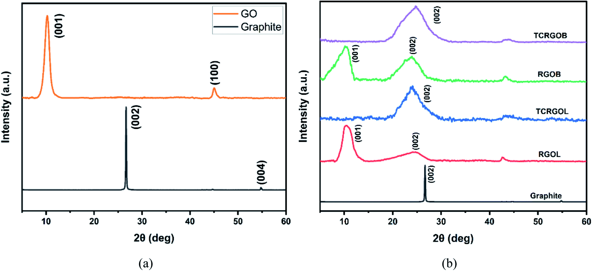 | ||
| Fig. 6 XRD patterns: (a) graphite and graphene oxide (GO) and (b) graphite and different reduced graphene oxides. | ||
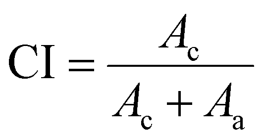
The XRD patterns of both reduced graphene oxide using L-ascorbic acid RGOL and sodium borohydride RGOB and their thermally treated equivalents are shown in Fig. 6(b). After the chemical reduction, RGOL and RGOB patterns showed 2θ = 24° while the GO characteristic peak at 10° peak remained visible. The relative intensity of the 2θ = 24° peak for the RGOB pattern reflects that the sodium borohydride (NaBH4) is a more effective reducing agent than the L-ascorbic acid.41 After the thermal treatment of both reduced forms (i.e., TCRGOL and TCRGOB), the peak at 2θ = 10° disappeared while the 2θ = 24° persisted indicating the transformation to an amorphous structure.42 The XRD pattern characteristic peak of TCRGOL and TCRGOB at 2θ = 24° matched 002 to establish the removal of functional groups and the expected partial recovery of the graphite-like structure.43 The crystallinity index (CI) was considered to detect the crystallinity percentage of the studied samples as follows:44
 | (11) |
|
nλ = 2dsinθ
| (12) |
Table 2 shows that the crystallinity structure becomes more amorphous with the restoration of graphene layers confirming that the chemical/thermal reduction route based on LAA (i.e., TCRGOL) is promising while the d-spacing calculation clarifies the typical graphite interspacing value (∼0.34 nm) between the layers, which dramatically increases with the oxidation and exfoliation treatment (i.e., improved Hummers' method) due to the introduction of the functional group expanding the space between the layers. After the reduction process, the spacing decreases reflecting the expected removal of functional groups.46,47
4.3 Thermogravimetric analysis (TGA)
Thermogravimetric analysis was conducted to detect the weight loss and thermal stability of graphite and different reduced forms of GO (i.e., RGOL, RGOB, TCRGOL, and TCRGOB). Fig. 7 indicates that the RGOL and RGOB, respectively, have 40% and 23% weight loss at 200 °C. The weight losses are due to water vapor evolution and the thermal decomposition of unstable oxygen-containing functional groups, such as hydroxyl, carbonyl, and alkoxy groups at the RGO's edges to produce CO, CO2, and H2O.48,49 As the temperature increases, the remaining oxygen-containing groups (e.g., epoxy) start to evolve releasing more CO and CO2 gases. This process creates distortions in the graphitic layer structure creating new structural defects in RGO layers.50 | ||
| Fig. 7 Thermogravimetric analysis (TGA) for graphite and different reduced graphene oxides. | ||
In light of this analysis, the chemically reduced graphene oxides (i.e., RGOL and RGOB) were thermally treated in a furnace at 200 °C under vacuum (1.5 bar) for 4 hours to obtain a higher degree of graphene sheet exfoliation depending on the pressure produced from the H2O, CO and CO2 evaporation. The produced samples were noted as TCRGOL and TCRGOB. After thermal treatment, the thermal stability of thermally treated RGO increases up to 500 °C, which is in agreement with the rule that the RGO's thermal stability increases with lower defects present in the layer structure.51 Above 500 °C, all samples start to deteriorate resulting in a highly defective layer structure due to the decomposition and sublimation of the carbon backbone.52,53
4.4 Electrical conductivity characterization
The conductivity (σ) of the studied samples at room temperature is demonstrated in Table 3. Graphite electrical conductivity was in the order of ∼104 [S m−1] scoring a value of 2.21 × 10⁴ [S m−1].54,55 After the improved Hummers' process and the formation of GO, the electrical conductivity decreases dramatically ∼0.5 [S m−1]. Upon the reduction, the electrical conductivity will be restored depending on the present amount of oxygenated functional group attached to the graphene layers.56,57 The L-ascorbic acid as a reducing agent produces the RGOL with 1.58 × 10³ [S m−1] and increased to 2.14 × 10³ [S m−1] after the thermal treatment. The sodium borohydride reduction approach RGOB is 2.04 × 10³ [S m−1] while after the thermal treatment the electrical conductivity decreases slightly with the value of 1.99 × 10³ [S m−1] due to the graphitic structure deterioration. Different reduction protocols lead to different RGO structures depending on their oxidation level and, hence, change in their electrical conductivity.| Sample | Conductivity (S m−1) |
|---|---|
| RGOL | 1575 ± 30 |
| TCRGOL | 2142 ± 23 |
| RGOB | 2036 ± 26 |
| TCRGOB | 1989 ± 20 |
It is well-known that the evaluation of RGO's electrical conductivity as a compressed powder is a challenging task since they are anisometric particles with a high surface area and, consequently, a high number of particle contacts affecting the bulk conductivity and lowering its values beyond the graphite. The values are therefore incomparable with graphite yet it remains practical for the sake of comparison with different RGO's when developing a new reduction synthesis protocol for carbon-based materials.58
The TCRGOL reduction protocol developed in this study provides the highest electrical conductivity value (2.14 × 10³ [S m−1]) over the other studied reduction approaches reflecting its high quality which enhances its performance with high expectations for a novel lightweight EMI shielding material.
4.5 Fourier transform infrared (FTIR) spectroscopy analysis
FTIR spectra of the graphite and RGO samples prepared with different reduction mechanisms are presented in Fig. 8 where the red line clarifies the vibrational stretching of C![[double bond, length as m-dash]](https://www.rsc.org/images/entities/char_e001.gif) C (v CC), which represents the RGO structure quality. First, the graphite peaks appear at 1570 cm−1 and 1220 cm−1 assigned for the vibrational stretching of CC (v CC) and vibrational stretching of C–O (v C–O) epoxy groups, respectively. The presence of the epoxy group clarifies that the starting material is a defected graphite.59
C (v CC), which represents the RGO structure quality. First, the graphite peaks appear at 1570 cm−1 and 1220 cm−1 assigned for the vibrational stretching of CC (v CC) and vibrational stretching of C–O (v C–O) epoxy groups, respectively. The presence of the epoxy group clarifies that the starting material is a defected graphite.59
 | ||
| Fig. 8 FTIR spectra of graphite and RGOs samples. | ||
The L-ascorbic acid as a reducing agent provides the RGO structure with (–OH) groups located at 3560 cm−1, the vibrational stretching of CO (v CO) at 1720 cm−1, the vibrational stretching of CC (v CC) at 1570 cm−1, the bending vibration of C–OH (δ C–OH) at 1400 cm−1, and finally two vibrational stretching C–O (v C–O) groups of epoxy and alkoxy at 1220 and 1040 cm−1, respectively. After the thermal treatment for RGOL samples, the structure was enhanced by restoring the vibrational stretching of CC (v CC) at 1570 cm−1 while the vibrational stretching of CO (v CO) at 1720 cm−1, the vibrational stretching of CC (v CC) at 1570 cm−1, and the vibrational stretching C–O (v C–O) epoxy groups at 1220 cm−1 are still present. This reflects the idea that the thermal treatment for RGO prepared by L-ascorbic acid is still able to exfoliate where the (–OH) groups, (δ C–OH) and the alkoxy groups have evolved in the form of gaseous products (e.g., CO, CO2, and H2O), providing sufficient pressure for more exfoliation to the graphene layers. Under these treatment conditions the RGO was able to restore the graphene structure and the quality was enhanced.
The sodium borohydride, which presents a different reduction mechanism, offers RGO with (–OH) groups, the vibrational stretching of CO (v CO), the vibrational stretching of CC (v CC), the bending vibration of C–OH (δ C–OH) and the vibrational stretching of C–O (v C–O) epoxy and alkoxy groups at 3560 cm−1, 1720 cm−1, 1570 cm−1, 1400 cm−1, 1220 and 1040 cm−1, respectively. From these results there is no doubt that the sodium borohydride is more efficient and favoured as a reducing agent in comparison with L-ascorbic acid. On the contrary, the tailored thermal treatment for RGOB increased the defective structure by evolving the CO and CO2 gases and deteriorating the graphene layer structure. Table 4 summarizes the FTIR analysis data for the studied samples.
| Sample | Wavenumber (cm−1) | Transmittance (%) | Functional groups |
|---|---|---|---|
| Graphite | 1237 | 96.9 | (v C–O) epoxy |
| 1517 | 98.9 | (v CC) |
|
| RGOL | 1043 | 87.8 | (v C–O) alkoxy |
| 1221 | 88.3 | (v C–O) epoxy | |
| 1406 | 95.5 | (δ C–OH) | |
| 1571 | 93.7 | (v CC) |
|
| 1724 | 94.8 | (v CO) |
|
| 3566 | 94.4 | (–OH) | |
| TCRGOL | 1204 | 84.2 | (v C–O) epoxy |
| 1568 | 86.3 | (v CC) |
|
| 1728 | 94.8 | (v CO) |
|
| RGOB | 1044 | 92.9 | (v C–O) alkoxy |
| 1220 | 94 | (v C–O) epoxy | |
| 1423 | 95.4 | (δ C–OH) | |
| 1573 | 95.3 | (v CC) |
|
| 1721 | 94.2 | (v CO) |
|
| 3527 | 97.5 | (–OH) | |
| TCRGOB | 1236 | 96.3 | (v C–O) epoxy |
| 1572 | 97 | (v CC) |
|
| 1728 | 94.6 | (v CO) |
From FTIR results, we can indicate that the developed thermal treatment for the L-ascorbic acid reduction route samples enhanced its quality with few defects while it was not effective for the other reduction mechanism under similar treatment conditions. So, the L-ascorbic acid reduction mechanism's type or any other similar mechanism is preferred to be thermally treated after the chemical reduction.
4.6 RAMAN spectroscopy analysis
RAMAN spectra were collected for graphite and reduced graphene oxide samples to detect detailed information about the graphitic structure and evaluate the reduction process.60 RAMAN data are presented in Fig. 9. All samples have D, G, and 2D bands located at ∼1350, ∼1600, and ∼2700 cm−1, respectively. The G band represents the relative vibrational motion of the sp2 hybridized carbon atom's graphitic structure. The D band intensity increases with the disorder in the sp2 hybridized carbon and defects present in the structure and reflects the strongly applied chemical treatment to the graphite. The ratio between the D and G bands (ID/IG) indicates the graphitization level of the carbonaceous samples and the highly intense peaks allow the implementation of a peak-to-peak height ratio. The low ratio confirms the successful reduction in restoring the graphitic structure, which provides better electrical conductivity and a higher shielding performance.61,62 The 2D band is always presented with graphitic samples and there is no need for defects to activate, like in the D band. It originated from the double-resonance impact, including a two-phonon scattering procedure, and represents the non-uniformity, number of layers, relative orientation, and different stacking. In contrast to the single graphene layer, the chemically reduced graphene oxides are distinguished with a broad 2D peak that covers from 2400 to 3100 cm−1 and usually consists of four components, 2D1B, 2D1A, 2D2A, and 2D2B. The broadness is due to the presence of a lattice disorder and layer defects.63,64 | ||
| Fig. 9 RAMAN spectra of graphite and RGOs. | ||
Graphite (e.g., the starting material) had an intense sharp G peak at 1585 cm−1 with the presence of D peak at 1351 cm−1, and with ID/IG equal to 0.34, which confirms it is defective graphite. It has a typical 2D peak at 2725 cm−1 and consists of two components, 2D1 and 2D2, with an I2D/IG ratio equal to 0.25.
The RGOL had a G peak detected at 1598 cm−1, and a D peak at 1357 cm−1, with an ID/IG ratio of 0.87. This increase was related to the presence of functional groups. While it has a broad 2D band characterized by 3 noticeable peaks located at 2719, 2928, and 3181 cm−1 with an I2D/IG ratio of 0.15, the broadness and low intensity of the 2D peak mean that we have a multilayer graphene structure. On the other hand, the RGOB peaks (G and D) were found at 1595 and 1357 cm−1, respectively, and the ID/IG ratio was 0.99, which reflects the presence of a highly defective structure and doping due to its reduction mechanism,9 even though it had a broad 2D band with two visible peaks at 2719, and 2922 cm−1 and an I2D/IG ratio of 0.1.
The thermal treatment of these RGO samples behaves differently. The TCRGOL RAMAN spectrum reveals an enhancement to the graphene structure with a G peak at 1600 and a D peak at 1359 cm−1, and an ID/IG ratio of 0.84. Also, its 2D peak broadness slightly changed as we detected two peaks at 2710 and 2926 cm−1, and the I2D/IG ratio was 0.16. The TCRGOL RAMAN results clarify that the thermal treatment done in this study did not increase the defects and enhanced its exfoliation providing a better graphene structure. Whereas the TCRGOB ID/IG ratio was 1.12 with G and D peaks at 1600 and 1356 cm−1, respectively, its barely remarkable broad 2D band at 2731 and 2924 cm−1 with a 0.05 I2D/IG ratio reflects that the thermal treatment causes a massive defect in the structure following the sodium borohydride reduction protocol. Moreover, the spectra were fitted using the Lorentzian curve fitting and full width at high maximum (FWHM) were retrieved to confirm the results.63,64
Fig. 10(a) illustrates the Lorentzian curve fitting for graphite, RGOL, TCRGOL, RGOB, and TCRGOB with 4, 5, 6, 7, and 5 fitted peaks, respectively. However, the 2D peak curve fitting is magnified and demonstrated in Fig. 10(b) where the graphite had a typical 2D band consisting of two peaks. In this study, the 2D band constituents for RGOL, TCRGOL, RGOB, and TCRGOB will be focused on the two major intense peaks known as 2D1A at 2700 cm−1 and 2D2A at 2920 cm−1, where the first reflects an indication about the number of layers and relative orientations while the later indicates the layer defects and its different stacking.65–67
 | ||
| Fig. 10 Raman curve fitting (a) Lorentzian curve fitting of graphite and RGOs, (b) 2D band curve fitting. | ||
The RGOL has a higher intense 2D2A peak than 2D1A (the ratio = 1.8) suggesting the presence of layer defects or different stacking due to the presence of functional groups in the lattice. The TCRGOL exhibits a more exfoliated structure with a nearly relative peak ratio between 2D1A and 2D2A and equal to 1.1 while the RGOB is 1, providing evidence for the enhancement of the graphene structure. At this point, we should consider the 2D band height intensity that provides an advantage to the TCRGOL samples. The TCRGOB presents one peak at 2723 cm−1 with a very low intensity (I2D/IG = 0.05) reflecting the truth about the criticality of the thermal treatment that starts to cause deterioration in the required graphitic structure. Finally, Table 5 summarizes the full width at height maximum (FWHM) for G and 2D peaks. According to the literature, the FWHM of the G peak increases when the disorder and defects increase, while the FWHM of the 2D peak increases with a decrease in the number of layers.68,69
| Sample | FWHM (G) peak | FWHM (2D) peak |
|---|---|---|
| Graphite | 19.9 | 77.1 |
| RGOL | 81.7 | 463.9 |
| TCRGOL | 67.8 | 539.5 |
| RGOB | 77.7 | 486.9 |
| TCRGOB | 75.2 | 514.1 |
The TCRGOL sample displays the lowest FWHM G peak and highest FWHM 2D peak values indicating that the thermal treatment for RGO samples reduced by L-ascorbic acid has relatively few defects and fewer layers than all the studied samples. These results confirm the advancement of the tailored reduction protocol based on the L-ascorbic acid, with expectations of high performance in many applications, especially for EMI shielding materials.
4.7 Electromagnetic measurements
The application of graphite and RGO's samples for EMI shielding production will be investigated as a compressed powder under appropriate forming conditions to evaluate the materials' shielding efficiency (SE) over the X-band (8.2–12.4 GHz) by a VNA line transmission waveguide method. The samples' SE behavior will be expressed in correlation to the employed amount per unit area (mass per area) known as areal density or area density (ρA). Furthermore, the samples will be investigated as a filler in some commercial matrices, such as silicon rubber and epoxy resins to confirm its SE behavior in composites.Fig. 11 elucidates the transmission losses (TL) in decibels (dB) for the studied samples as a compressed powder in a waveguide sample holder in terms of area density. Each sample was evaluated and linearly fitted with three different quantities. The TCRGOL exhibits a −94 dB average (TL) value over the X-band with 0.08 g cm−2 while the highest (TL) value was −98 dB scored with 0.6 g cm−2 of graphite. So, the TCRGOL exhibits the highest TL over all the other reduced graphene forms even surpassing the RGOB transmission losses by 175% applying the same areal density. The TCRGOL is a step forward for the final weight of the shielding products by providing the same total shielding efficiency (SET) with 13% of required graphite amounts as demonstrated in Fig. 11(a).
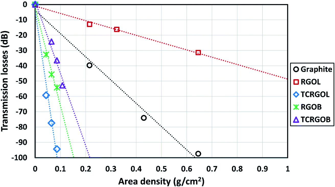 | ||
| Fig. 11 Graphite and RGOs transmission losses with linear relation identification. | ||
The SET is based on the ability of the materials to absorb the incident electromagnetic waves rather than reflection. Fig. 12(b) illustrates the absorption shielding efficiency (SEA) of the evaluated samples.
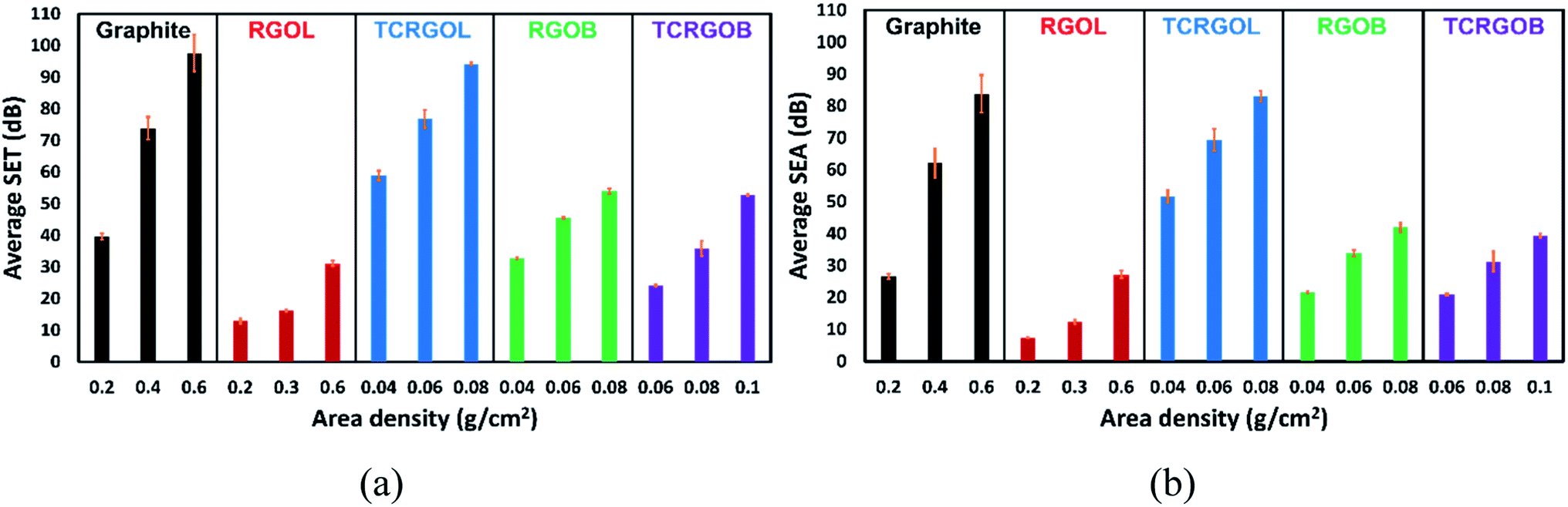 | ||
| Fig. 12 Averaged shielding effectiveness (SE) over the X-band from 8.2 to 12.4 GHz: (a) total (SET), (b) absorbance (SEA), the error bars represent standard deviations. | ||
The SET and SEA behavior of the highest load capacity of each sample over the X-band are presented in Fig. 13(a) and (b), respectively. The TCRGOL's total shielding efficiency performance is steady and stable over the X-band and equal to 94 dB with a 1 dB deviation. The detailed data of all studied compressed samples are shown in Table 6.
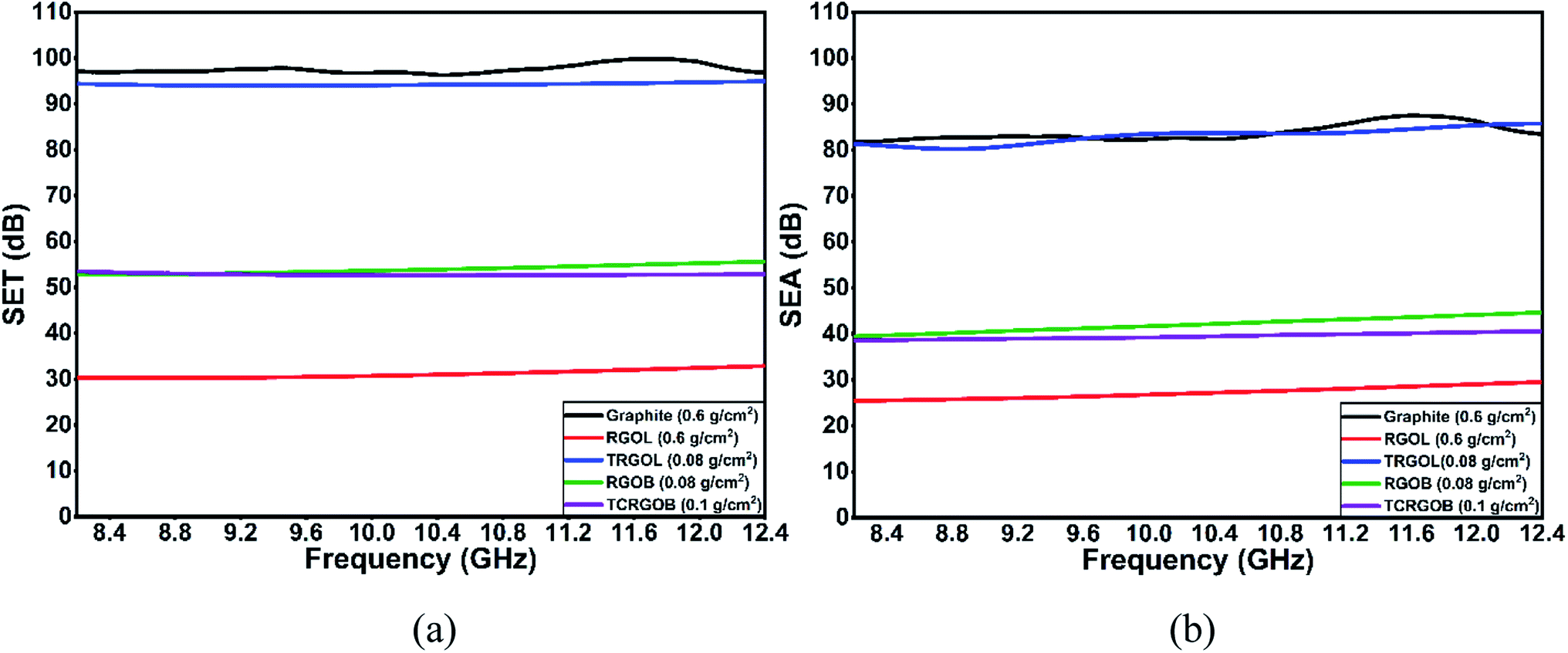 | ||
| Fig. 13 Shielding effectiveness (SE) over the X-band from 8.2 to 12.4 GHz: (a) total (SET), (b) absorbance (SEA). | ||
| Sample | Area density (g cm−2) | SER (dB) | SEA (dB) | SET (dB) |
|---|---|---|---|---|
| Graphite | 0.2 | 13 ± 2 | 26 ± 1 | 39 ± 2 |
| 0.4 | 12 ± 2 | 62 ± 5 | 74 ± 4 | |
| 0.6 | 14 ± 1 | 84 ± 6 | 98 ± 6 | |
| RGOL | 0.2 | 6 ± 1 | 7 ± 1 | 13 ± 1 |
| 0.4 | 4 ± 1 | 12 ± 1 | 16 ± 1 | |
| 0.6 | 4 ± 1 | 27 ± 1 | 31 ± 1 | |
| TCRGOL | 0.04 | 7 ± 1 | 52 ± 2 | 59 ± 2 |
| 0.06 | 7 ± 1 | 70 ± 3 | 77 ± 3 | |
| 0.08 | 11 ± 2 | 83 ± 2 | 94 ± 1 | |
| RGOB | 0.04 | 11 ± 1 | 22 ± 1 | 33 ± 1 |
| 0.06 | 12 ± 1 | 34 ± 1 | 46 ± 1 | |
| 0.08 | 12 ± 1 | 42 ± 2 | 54 ± 1 | |
| TCRGOB | 0.06 | 3 ± 1 | 21 ± 1 | 24 ± 1 |
| 0.08 | 5 ± 1 | 31 ± 3 | 36 ± 2 | |
| 0.1 | 13 ± 1 | 40 ± 1 | 53 ± 1 |
From the above results, a high-quality reduced graphene oxide (i.e., 7 layers) was achieved for the first time based on the top-down synthesis technique, through the chemical reduction of graphene oxide using L-ascorbic acid as the reducing agent, followed by a simple and effective thermal treatment offering a superior performance as a shielding agent over other studied shielding samples for various civilian and military applications.
5. Conclusions
The top-down synthesis method through the chemical reduction of graphene oxide is the most promising route for large-scale production at the current stage of graphene research. This approach suffers from poor RGO quality with many defects due to the severe chemical treatment during the production process compared with other graphene preparation techniques, such as the chemical vapor deposition (CVD), and is still less effective than the thermal reduction methods. Also, the safety issues with some types of reducing agents that may involve toxic or flammable gases during the production make a great case to look for a safe, non-toxic reducing agent, such as L-ascorbic acid.This work presents the development and characterization of high-quality reduced graphene oxide (TCRGOL) based on L-ascorbic acid as the reductant using an easy, scalable, high yield, and reliable two-stage protocol by applying the chemical reduction to GO followed by a thermal treatment under mild conditions, which surpasses other studied reduction routes (RGOL, RGOB, and TCRGOB). In addition, the study highlights the tolerance concerning the thermal treatment as a second step clarifying its criticality on the reduction mechanism used in the chemical process.
Furthermore, the study correlates the dependence of EMI shielding efficiency (SE) over the X-band with the different RGO preparation protocols. The tailored TCRGOL exhibits high shielding efficiency with very low amounts in comparison with the reference material graphite and the other reduction approaches achieving 94 dB of total shielding efficiency with 0.08 g cm−2 load capacity over the X-band from 8.2 to 12.4 GHz. The high-performance leads to a reliable and affordable lightweight EMI shielding material for several shielding applications, such as foams, paints, flexible sheets, etc., and paves the way for future hybrid composites investigation.
The developed two-step protocol presented in this work provides a scalable, affordable, and safe technique of RGO production, and overcomes the traditional chemical and thermal reduction approach drawbacks by enhancing the RGO quality, avoiding harm-reducing agents, the evolution of toxic or flammable gases, and the high temperature with ambient atmosphere restrictions. It exploits the advantage of the mild reduction property of L-ascorbic acid to put it in the foreground for diverse civilian and military applications, especially, EMI shielding carbon-based materials.
Conflicts of interest
There are no conflicts to declare.Acknowledgements
The authors gratefully acknowledge support for this research from Sylvain Simard Fleury (EM shielding sample holder fabrication), Matthieu Gauthier (SEM), Jean-Philippe Masse and the Centre for Characterization and Microscopy of Materials (CM)2 for (TEM), Chi-hyeong Kim (4-point probe), and Louis-Philippe Carignan (VNA assistance) and the Poly-Grames research center for providing the measurement setup of the microwave characterization.References
- G. Redlarski, et al., The Influence of Electromagnetic Pollution on Living Organisms: Historical Trends and Forecasting Changes, BioMed Res. Int., 2015, 2015, 234098, DOI:10.1155/2015/234098.
- A. Perrin and M. Souques, Electromagnetic Fields, Environment and Health, Springer Paris, 2013 Search PubMed.
- N. Violette, Electromagnetic Compatibility Handbook, Springer Netherlands, 2013 Search PubMed.
- R. J. Perez, Handbook of Aerospace Electromagnetic Compatibility, Wiley, 2018 Search PubMed.
- D. Jiang, et al., Electromagnetic Interference Shielding Polymers and Nanocomposites - A Review, Polym. Rev., 2019, 59(2), 280–337, DOI:10.1080/15583724.2018.1546737.
- J. P. Gogoi and A. Shabir, Chapter 23 - High-temperature electromagnetic interference shielding materials, in Materials for Potential EMI Shielding Applications, ed. K. Joseph, R. Wilson, and G. George, Elsevier, 2020, pp. 379–390 Search PubMed.
- M. Hotta, M. Hayashi, M. T. Lanagan, D. K. Agrawal and K. Nagata, Complex Permittivity of Graphite, Carbon Black and Coal Powders in the Ranges of X-band Frequencies (8.2 to 12.4 GHz) and between 1 and 10 GHz, ISIJ Int., 2011, 51(11), 1766–1772, DOI:10.2355/isijinternational.51.1766.
- A. K. Geim and K. S. Novoselov, The rise of graphene, in Nanoscience and Technology: a Collection of Reviews from Nature Journals, World Scientific, 2010, pp. 11–19 Search PubMed.
- C. K. Chua and M. Pumera, Chemical reduction of graphene oxide: a synthetic chemistry viewpoint, Chem. Soc. Rev., 2014, 43(1), 291–312 RSC.
- J. Cao, et al., Two-step electrochemical intercalation and oxidation of graphite for the mass production of graphene oxide, J. Am. Chem. Soc., 2017, 139(48), 17446–17456 CrossRef CAS.
- A. M. Dimiev and S. Eigler, Graphene Oxide: Fundamentals and Applications, Wiley, 2016 Search PubMed.
- D. C. Marcano, et al., Improved Synthesis of Graphene Oxide, ACS Nano, 2010, 4(8), 4806–4814, DOI:10.1021/nn1006368.
- T.-P. Teng, S.-C. Chang, Z.-Y. Chen, C.-K. Huang, S.-F. Tseng and C.-R. Yang, High-yield production of graphene flakes using a novel electrochemical/mechanical hybrid exfoliation, The International Journal of Advanced Manufacturing Technology, 2019, 104(5), 2751–2760 CrossRef.
- A. Kaniyoor, T. T. Baby, T. Arockiadoss, N. Rajalakshmi and S. Ramaprabhu, Wrinkled graphenes: a study on the effects of synthesis parameters on exfoliation-reduction of graphite oxide, J. Phys. Chem. C, 2011, 115(36), 17660–17669 CrossRef CAS.
- D. Luo, G. Zhang, J. Liu and X. Sun, Evaluation criteria for reduced graphene oxide, J. Phys. Chem. C, 2011, 115(23), 11327–11335 CrossRef CAS.
- C. Botas, et al., Critical temperatures in the synthesis of graphene-like materials by thermal exfoliation–reduction of graphite oxide, Carbon, 2013, 52, 476–485 CrossRef CAS.
- K. K. H. De Silva, H.-H. Huang, R. Joshi and M. Yoshimura, Restoration of the graphitic structure by defect repair during the thermal reduction of graphene oxide, Carbon, 2020, 166, 74–90 CrossRef CAS.
- X. Gao, J. Jang and S. Nagase, Hydrazine and thermal reduction of graphene oxide: reaction mechanisms, product structures, and reaction design, J. Phys. Chem. C, 2010, 114(2), 832–842 CrossRef CAS.
- W. Gao, L. B. Alemany, L. Ci and P. M. Ajayan, New insights into the structure and reduction of graphite oxide, Nat. Chem., 2009, 1(5), 403–408 CrossRef CAS PubMed.
- H. J. Shin, et al., Efficient reduction of graphite oxide by sodium borohydride and its effect on electrical conductance, Adv. Funct. Mater., 2009, 19(12), 1987–1992 CrossRef CAS.
- J. Zhang, H. Yang, G. Shen, P. Cheng, J. Zhang and S. Guo, Reduction of graphene oxide via L-ascorbic acid, Chem. Commun., 2010, 46(7), 1112–1114 RSC.
- K. K. H. De Silva, H.-H. Huang and M. Yoshimura, Progress of reduction of graphene oxide by ascorbic acid, Appl. Surf. Sci., 2018, 447, 338–346 CrossRef CAS.
- K. Erickson, R. Erni, Z. Lee, N. Alem, W. Gannett and A. Zettl, Determination of the local chemical structure of graphene oxide and reduced graphene oxide, Adv. Mater., 2010, 22(40), 4467–4472 CrossRef CAS PubMed.
- J. Gao, F. Liu, Y. Liu, N. Ma, Z. Wang and X. Zhang, Environment-friendly method to produce graphene that employs vitamin C and amino acid, Chem. Mater., 2010, 22(7), 2213–2218 CrossRef CAS.
- H. C. Schniepp, et al., Functionalized single graphene sheets derived from splitting graphite oxide, J. Phys. Chem. B, 2006, 110(17), 8535–8539 CrossRef CAS PubMed.
- W. Chen and L. Yan, Preparation of graphene by a low-temperature thermal reduction at atmosphere pressure, Nanoscale, 2010, 2(4), 559–563 RSC.
- S. N. Alam, N. Sharma and L. Kumar, Synthesis of graphene oxide (GO) by modified hummers method and its thermal reduction to obtain reduced graphene oxide (rGO), Graphene, 2017, 6(1), 1–18 CrossRef CAS.
- I. Sengupta, S. Chakraborty, M. Talukdar, S. K. Pal and S. Chakraborty, Thermal reduction of graphene oxide: How temperature influences purity, J. Mater. Res., 2018, 33(23), 4113–4122 CrossRef CAS.
- D. Mhamane, et al., From graphite oxide to highly water dispersible functionalized graphene by single step plant extract-induced deoxygenation, Green Chem., 2011, 13(8), 1990–1996 RSC.
- N. Saadatkhah, et al., Experimental methods in chemical engineering: Thermogravimetric analysis—TGA, Can. J. Chem. Eng., 2020, 98(1), 34–43 CrossRef CAS.
- I. Miccoli, F. Edler, H. Pfnür and C. Tegenkamp, The 100th anniversary of the four-point probe technique: the role of probe geometries in isotropic and anisotropic systems, J. Phys.: Condens. Matter, 2015, 27(22), 223201 CrossRef CAS.
- Ossila, Sheet Resistance Equations and Theory | Complete Guide, Ossila Ltd, https://www.ossila.com/pages/sheet-resistance-theory, accessed Search PubMed.
- J. R. Baker-Jarvis et al., Measuring the Permittivity and Permeability of Lossy Materials: Solids, Liquids, Metals, and Negative-index Materials, 2005 Search PubMed.
- H. R. Tantawy, D. E. Aston, J. R. Smith and J. L. Young, Comparison of Electromagnetic Shielding with Polyaniline Nanopowders Produced in Solvent-Limited Conditions, ACS Appl. Mater. Interfaces, 2013, 5(11), 4648–4658, DOI:10.1021/am401695p.
- M. H. Al-Saleh and U. Sundararaj, Electromagnetic interference shielding mechanisms of CNT/polymer composites, Carbon, 2009, 47(7), 1738–1746 CrossRef CAS.
- S. Nagarajan, G. Karthik, J. K. Jose and H. C. Barshilia, Sprayable reduced graphene oxide based high-temperature solar absorber coatings for concentrated solar power applications, Int. J. Energy Res., 2021, 45(15), 21487–21496, DOI:10.1002/er.7196.
- Z. H. Ni, et al., Graphene Thickness Determination Using Reflection and Contrast Spectroscopy, Nano Lett., 2007, 7(9), 2758–2763, DOI:10.1021/nl071254m.
- A. Al-Hagri, et al., Direct growth of single-layer terminated vertical graphene array on germanium by plasma enhanced chemical vapor deposition, Carbon, 2019, 155, 320–325 CrossRef CAS.
- V. Kumar, A. Kumar, D.-J. Lee and S.-S. Park, Estimation of Number of Graphene Layers Using Different Methods: A Focused Review, Materials, 2021, 14(16), 4590 CrossRef CAS.
- Y. Bai, H. Cai, X. Qiu, X. Fang and J. Zheng, Effects of graphene reduction degree on thermal oxidative stability of reduced graphene oxide/silicone rubber nanocomposites, High Perform. Polym., 2015, 27(8), 997–1006 CrossRef CAS.
- G. Yasin, et al., Exploring the nickel–graphene nanocomposite coatings for superior corrosion resistance: manipulating the effect of deposition current density on its morphology, mechanical properties, and erosion-corrosion performance, Adv. Eng. Mater., 2018, 20(7), 1701166 CrossRef.
- G. Liu, L. Wang, B. Wang, T. Gao and D. Wang, A reduced graphene oxide modified metallic cobalt composite with superior electrochemical performance for supercapacitors, RSC Adv., 2015, 5(78), 63553–63560 RSC.
- R. Mei, X. Song, Y. Hu, Y. Yang and J. Zhang, Hollow reduced graphene oxide microspheres as a high-performance anode material for Li-ion batteries, Electrochim. Acta, 2015, 153, 540–545 CrossRef CAS.
- A. Khan, et al., Influence of Fe doping on the structural, optical and thermal properties of α-MnO2 nanowires, Mater. Res. Express, 2019, 6(6), 065043 CrossRef CAS.
- B. Cullity and S. Stock, Elements of X-ray Diffraction, New York, 3rd edn, Pearson, 2014, p. 654 Search PubMed.
- R. S. Rajaura, et al., Role of interlayer spacing and functional group on the hydrogen storage properties of graphene oxide and reduced graphene oxide, Int. J. Hydrogen Energy, 2016, 41(22), 9454–9461 CrossRef CAS.
- J. Um, S. U. Yoon, H. Kim, B. S. Youn, H.-J. Jin, H.-K. Lim and Y. S. Yun, High-performance solid-solution potassium-ion intercalation mechanism of multilayered turbostratic graphene nanosheets, J. Energy Chem., 2022, 67, 814–823 CrossRef.
- S. Alam, N. Sharma and L. Kumar, Synthesis of graphene oxide (GO) by modified hummers method and its thermal reduction to obtain reduced graphene oxide (rGO)*, Graphene, 2017, 06, 1–18 CrossRef CAS.
- C. Zhang, X. Fu, Q. Yan, J. Li, X. Fan and G. Zhang, Study on the thermal decomposition mechanism of graphene oxide functionalized with triaminoguanidine (GO-TAG) by molecular reactive dynamics and experiments, RSC Adv., 2019, 9(57), 33268–33281 RSC.
- A. E. e. Galashev and O. R. Rakhmanova, Mechanical and thermal stability of graphene and graphene-based materials, Phys.-Usp., 2014, 57(10), 970 CrossRef CAS.
- F. Farivar, et al., Unlocking thermogravimetric analysis (TGA) in the fight against “Fake graphene” materials, Carbon, 2021, 179, 505–513 CrossRef CAS.
- H. Y. Nan, Z. H. Ni, J. Wang, Z. Zafar, Z. X. Shi and Y. Y. Wang, The thermal stability of graphene in air investigated by Raman spectroscopy, J. Raman Spectrosc., 2013, 44(7), 1018–1021 CrossRef CAS.
- J. Shen, Y. Hu, C. Li, C. Qin and M. Ye, Synthesis of amphiphilic graphene nanoplatelets, Small, 2009, 5(1), 82–85 CrossRef CAS PubMed.
- I. L. Spain, Electronic transport properties of graphite, carbons, and related materials, Chemistry and Physics of Carbon, 2021, pp. 119–304 Search PubMed.
- N. Deprez and D. McLachlan, The analysis of the electrical conductivity of graphite conductivity of graphite powders during compaction, J. Phys. D: Appl. Phys., 1988, 21(1), 101 CrossRef CAS.
- V. B. Mohan, R. Brown, K. Jayaraman and D. Bhattacharyya, Characterisation of reduced graphene oxide: Effects of reduction variables on electrical conductivity, Mater. Sci. Eng., B, 2015, 193, 49–60 CrossRef CAS.
- B. Alemour, M. Yaacob, H. Lim and M. R. Hassan, Review of Electrical Properties of Graphene Conductive Composites, International Journal of Nanoelectronics and Materials, 2018, 11(4), 371–398 Search PubMed.
- B. Marinho, M. Ghislandi, E. Tkalya, C. E. Koning and G. de With, Electrical conductivity of compacts of graphene, multi-wall carbon nanotubes, carbon black, and graphite powder, Powder Technol., 2012, 221, 351–358 CrossRef CAS.
- N. Bandara, Y. Esparza and J. Wu, Graphite oxide improves adhesion and water resistance of canola protein–graphite oxide hybrid adhesive, Sci. Rep., 2017, 7(1), 1–12 CrossRef CAS.
- E. I. Bîru and H. Iovu, Graphene nanocomposites studied by Raman spectroscopy, Raman Spectroscopy, IntechOpen, 2018, ch. 9, pp. 179–201, DOI:10.5772/intechopen.73487.
- S. Repp, et al., Synergetic effects of Fe3+ doped spinel Li4Ti5O12 nanoparticles on reduced graphene oxide for high surface electrode hybrid supercapacitors, Nanoscale, 2018, 10(4), 1877–1884, 10.1039/C7NR08190A.
- M. Buldu-Akturk, M. Toufani, A. Tufani and E. Erdem, ZnO and reduced graphene oxide electrodes for all-in-one supercapacitor devices, Nanoscale, 2022, 14(8), 3269–3278, 10.1039/D2NR00018K.
- A. C. Ferrari and D. M. Basko, Raman spectroscopy as a versatile tool for studying the properties of graphene, Nat. Nanotechnol., 2013, 8(4), 235–246 CrossRef CAS PubMed.
- D. López-Díaz, M. Lopez Holgado, J. L. García-Fierro and M. M. Velázquez, Evolution of the Raman spectrum with the chemical composition of graphene oxide, J. Phys. Chem. C, 2017, 121(37), 20489–20497 CrossRef.
- C. Casiraghi, et al., Raman spectroscopy of graphene edges, Nano Lett., 2009, 9(4), 1433–1441 CrossRef CAS PubMed.
- A. Jorio, M. S. Dresselhaus, R. Saito, and G. Dresselhaus, Raman spectroscopy in Graphene Related Systems, John Wiley & Sons, 2011 Search PubMed.
- D. Yoon, H. Moon, H. Cheong, J. S. Choi, J. A. Choi and B. H. Park, Variations in the Raman spectrum as a function of the number of graphene layers, J. Korean Phys. Soc., 2009, 55(3), 1299–1303 CrossRef CAS.
- E. M. Ferreira, et al., Evolution of the Raman spectra from single-, few-, and many-layer graphene with increasing disorder, Phys. Rev. B, 2010, 82(12), 125429 CrossRef.
- A. Jorio, E. H. M. Ferreira, M. V. Moutinho, F. Stavale, C. A. Achete and R. B. Capaz, Measuring disorder in graphene with the G and D bands, Phys. Status Solidi B, 2010, 247(11–12), 2980–2982 CrossRef CAS.
| This journal is © The Royal Society of Chemistry 2022 |