
 Open Access Article
 This Open Access Article is licensed under a
 Creative Commons Attribution 3.0 Unported Licence
Photocatalytic hydrogen production and storage in carbon nanotubes: a first-principles study†
Xiaohan Song a,
Hongxia Bub,
Yingcai Fanc,
Junru Wangd and
Mingwen Zhao*e
a,
Hongxia Bub,
Yingcai Fanc,
Junru Wangd and
Mingwen Zhao*e
aShandong Institute of Advanced Technology, Jinan, Shandong 250100, China
bCollege of Physics and Electronic Engineering, Qilu Normal University, Jinan, Shandong 250200, China
cSchool of Information and Electronic Engineering, Shandong Technology and Business University, Yantai, Shandong 264005, China
dDepartment of Physics, Yantai University, Yantai, Shandong 264005, China
eSchool of Physics and State Key Laboratory of Crystal Materials, Shandong University, Jinan, Shandong 250100, China. E-mail: zmw@sdu.edu.cn
First published on 8th June 2022
Abstract
As it is a promising clean energy source, the production and storage of hydrogen are crucial techniques. Here, based on first-principles calculations, we proposed an integral strategy for the production and storage of hydrogen in carbon nanotubes via photocatalytic processes. We considered a core–shell structure formed by placing a carbon nitride nanowire inside a carbon nanotube to achieve this goal. Photo-generated holes on the carbon nanotube surface promote water splitting. Driven by intrinsic electrostatic field in the core–shell structures, protons produced by water splitting penetrate the carbon nanotube and react with photo-generated electrons on the carbon nitride nanowire to produce hydrogen molecules in the carbon nanotube. Because carbon nanotubes have high hydrogen storage capacity, this core–shell structure can serve as a candidate system for photocatalytic water splitting and safe hydrogen storage.
Introduction
Hydrogen energy has attracted a great deal of attention as a sort of clean energy resource. The hydrogen production via photocatalytic overall water splitting is a regenerative, eco-friendly, and inexhaustible approach, where photocatalysts play a key role.1–3 The photocatalysts employed in these processes should have high absorption ability to light, suitable band gap and band edges that match with the redox potentials of water splitting, and high redox ability of the photogenerated carriers. So far, a large number of photocatalysts, such as metal-free photocatalysts, metal oxides, metal chalcogenides and so on, have been developed for hydrogen production from water splitting.4–12 Among these semiconductor catalysts, carbon-based materials were intensively studied because of their excellent catalytic performance.13–20 Graphitic carbon nitride (g-C3N4) with proper band edges has been widely studied, but its photocatalytic performance is hindered by poor light-harvesting ability and low charge mobilities.21–28 Fortunately, the construction of heterojunctions or modifications can improve the aforesaid problems.29The separation and storage of the generated hydrogen molecules in the photocatalytic water splitting processes are also crucial. In order to avoid the reverse reaction and possible dangerous explosion, hydrogen should be isolated from the oxygen products during water oxidation. Recently, Yang et al. reported that photocatalytic hydrogen generation and hydrogen storage can be realized in a two-dimensional multilayer system, where carbon nitride monolayer is sandwiched between two monolayers of graphene.30 The key is that the outer graphene layers allow only protons to pass through, separating the production and storage of hydrogen and oxygen.31 But the storage rate of hydrogen is limited by the interlayer distance, as effective interlayer charge transfer distance between 2D material is ∼7 Å.32,33
Carbon nanotubes (CNTs) have been widely studied for hydrogen storage due to abundant carbon elements, light mass density, highly and controllable porous structure, and good interaction between carbon and hydrogen molecules.34 But one challenge in storing hydrogen inside CNTs is how to put hydrogen in it. Notably, various nanowires have been successfully encapsulated in carbon nanotubes, such as carbon chain, metal nanowires, nitride nanowires, carbide nanowires and so on.35–39 Supposing a photosensitive material is placed inside a CNT, it will conduct photocatalytic reaction and generate hydrogen molecules inside the CNT. Because only the protons are allowed to pass through the wall of CNT,31 the produced hydrogen molecules are separated from oxygen, achieving safe and stable storage of hydrogen inside CNTs. The double-walled nanotubes can also achieve this goal.40
Using first-principles calculations, we proved the rationality and feasibility of this strategy in CNT containing a carbon nitride nanowire (CNNW). The electronic structures, separation of the photo-generated carriers and the subsequent chemical reactions in this photocatalytic system were systematically investigated. Our calculations showed that the oxygen evolution reaction (OER) and hydrogen evolution reaction (HER) take place on the outside wall of CNTs and the inner CNNWs, respectively, driven by the photo-generated carriers, enabling the separation and storage of hydrogen in CNTs. In view of the high hydrogen storage capacity of carbon nanotubes, this core–shell structure can serve as a candidate system for photocatalytic water splitting and safe hydrogen storage.
Computational methods
Our density functional theory (DFT) calculations were performed by using the Vienna Ab-initio Simulation Package (VASP) code.41 The electron–ion interactions and the electron–electron exchange–correlation were respectively described by the projector augmented wave (PAW) method42 and the generalized gradient approximation (GGA)43 in the form of Perdew–Burke–Ernzerhof (PBE) functional.44 The hybrid Heyd–Scuseria–Ernzerhof (HSE06) functional45 was used for accurately calculating the band structures. The van der Waals (vdW) interaction between CNT and CNNW was described by the DFT-D2 Grimme's method.46 The energy cutoff was set to 520 eV. The conjugate gradient (CG) algorithm was used to fully relax all the atom positions and the lattice constants. The convergence criteria for energy and force was 10−5 eV and 0.01 eV Å−1, respectively. A periodic boundary condition was applied along the axial (z-) direction of the CNT and CNNW, while a vacuum space of about 30 Å was included along the lateral (x- and y-) direction to avoid the interaction between the adjacent images. The Brillouin zone was sampled with the Monkhorst-Pack k-points meshes of 1 × 1 × 15 for CNTs, 1 × 1 × 7 for CNNWs and the core/shell structures, respectively.47 The electron transfer between the inner CNNWs and the outer CNTs was calculated by means of Bader analysis.48 We use the climbing image nudged elastic band (CNEB) method,49 which was implemented in the VASP transition state tools, to determine the energetic minimal path profiles for the water splitting at the CNTs surface. The nonadiabatic molecular dynamics (NAMD) simulations were also performed to examine the spatial evolution of photogenerated carriers based on the Hefei-NAMD code.50 The detailed description of NAMD can be found in the ESI.†The HER pathways were calculated according to the electrochemical framework developed by Nørskov et al.,51 the HER overall two-electron transfer reaction process in an acid electrolyte can be written as:
| H+ + e− + * ⇌ H* ⇌ 1/2H2(g) + * |
| ΔG = ΔE + ΔEZPE − TΔS + ΔGU |
| η = −|ΔGH*|/e |
Results and discussion
To achieve photocatalytic water splitting, the band gap of the photocatalysts should be at least 1.23 eV, which correspond the energy difference between hydrogen reduction potential (H+/H2) and water oxidation potential (O2/H2O). In this work, we took two CNNWs, C6N6 and C12N4 (Fig. 1a) as the photocatalysts. The lattice constants of the C6N6 and C12N4 nanowires are respectively 7.13 Å and 8.32 Å. The bandgaps, 3.65 eV (for C6N6) and 2.51 eV (for C12N4), and the band edge alignment as shown in Fig. S1 and S2,† fulfill the requirement of photocatalytic water splitting. The optical adsorption peaks of these CNNWs reside at the ultraviolet light regime, as shown in Fig. S3.† | ||
| Fig. 1 (a) The models of carbon nitride nanowires: C6N6 and C12N4. (b) The models of carbon nanotubes: (10,10) armchair CNT (aCNT) and (17,0) zigzag CNT (zCNT). (c) The solar-driven photocatalytic water splitting and safe hydrogen storage scheme: (1) separation of photo-generated carries; (2) photo-generated carriers promote water splitting to generate proton (H+); (3) proton penetrate the wall of CNTs, hydrogen generation and storage. Blue, grey, orange and red beads represent N, C, H (H+) and O atoms, the blue and orange clouds are photo-generated carries (e− and h+), and the orange arrows denote the particles migration. | ||
We considered two types of CNTs, (10,10) armchair CNT (aCNT) and (17,0) zigzag CNT (zCNT), as shown in Fig. 1b. The diameters of aCNT and zCNT are respectively 13.64 Å and 13.42 Å. In order to effectively reduce lattice mismatch, the core–shell structures were constructed by using similar shaped materials along radial direction. C6N6 and C12N4 nanowires were placed in the two CNTs, respectively, which are denoted as C6N6/aCNT and C12N4/zCNT, as shown Fig. 1c. The lattice parameters of C6N6/aCNT and C12N4/zCNT were set to be c = 7.27 Å and 8.44 Å, corresponding to the average values of the CNNWs and CNTs. We define the formation energy as Ef = ECNNW/CNT − ECNNW − ECNT, where ECNNW/CNT, ECNNW and ECNT represent energies of the CNNW/CNT structures, CNNW and CNT, respectively. Our calculations showed that C6N6/aCNT and C12N4/zCNT have similar minimum equilibrium interfacial distances between CNT and CNNW of 3.60 Å and 3.37 Å and formation energies of 0.89 eV and 0.14 eV, suggesting the weak vdW interaction between the two components. The semiconducting features of the CNNWs are well preserved with reduced bandgap in the core–shell structures (Fig. S1†). And these core–shell structures have direct bandgaps at the Γ point, the conduction band minimum (CBM) and valence band maximum (VBM) is dominated by CNNWs and CNTs, respectively. The range of light absorption has also been extended to visible and ultraviolet light (Fig. S3†).
The production and storage of hydrogen in these core–shell structures via photocatalytic processes are illustrated in Fig. 1c. (1) The core/shell structure generates excitons by absorbing visible or ultraviolet light. The subsequent charge separation i.e., electrons reside on the inner CNNWs while holes transfer to outer CNTs, facilitates the following reactions. (2) The holes on CNTs (CNTsCv) facilitate water adsorption to defect sites on CNTs surface and subsequent water splitting to generate protons (H+). (3) Under the action of electrostatic attraction driving force, the generated H+ penetrate the wall of CNTs and reach the N sites of CNNWs. (4) Driven by the photo-generated electrons in CNNW, HER takes place, producing H2 molecules inside the CNT. The produced H2 molecules cannot penetrate the wall of CNTs and thus are retained inside CNTs, realizing the purpose of safe capsule storage.
We first investigated the separation of photo-generated carriers in the photocatalytic systems. The direction of charge transfer can be predicted from the work function (WF) of the materials. Electrons prefer to transfer from a low WF material to a high WF material.52 Our calculations showed that CNNWs have higher WFs than those of CNTs, as shown in Fig. S4.† This is also consistent with Bader analysis for the neutral core–shell structures at the equilibrium state. The inner C6N6 and C12N4 NWs gain 0.082 and 0.068 electrons from the CNTs, respectively, exhibiting that the electrons are well separated from the hole carriers, as shown in Fig. S5.† The electron transfer also induces a built-in electric field in the core–shell structures, which promotes the subsequent separation of the photo-generated carriers and then proton penetration through the wall of CNTs.
Additionally, we also mimicked the spatial distribution of the photo-generated electrons in the CNNW/CNT structures. We plotted the band edge alignment of the CNNW/CNT structures (Fig. S2b and c†). The results showed CNNW/CNT structures have the staggered band alignment, in which electron and hole carriers are spatially separated. Band-decomposed charge density distributions for the CBM and VBM of CNNW/CNT structures also showed that the VBM are localized at the CNTs and the CBM are contributed by the CNNWs (Fig. S6†). The inner CNNWs accumulate electrons, whereas outer CNTs always collect hole carriers, as shown in Fig. 2. Bader charge analysis indicates that about 0.246 and 0.275 e− accumulate on the C6N6 and C12N4 NWs, as an additional electron was added into the unit cell of the photocatalytic systems, while the CNTs could collect 1.031 and 1.072 h+ for the hole-doped systems, respectively. The NAMD simulations showed that the hole on CNTs would almost not transfer to the CNNWs within 0.5 ps, while more than 50% electron carriers on the CNTs would transfer to the CNNWs within 0.3 ps and 0.4 ps respectively for C6N6/aCNT and C12N4/zCNT (Fig. S7†). This suggested that photo-generated electrons and holes are distributed on CNNWs and CNTs respectively.
 | ||
| Fig. 2 Charge density difference of the C6N6/aCNT and C12N4/zCNT structures with one extra electron (a and b) and hole (c and d). The isovalue was 2 × 10⁻³e/Å3. Yellow regions and blue regions indicate electron accumulation and loss, respectively. | ||
Water splitting processes starts with the water molecule adsorption on the surface of CNTs. We only need to produce protons in this step. The introduction of vacancy defects and single-atom catalysts, such as Fe, Co, Ni, Cu, Zn etc., on the wall of CNTs can improve the activity of the photocatalytic systems and lifetime of photogenerated carriers.53 Here we introduced a vacancy defect on the wall of CNTs (CNTsCv) as an example. The adsorption energy of H2O molecule on the vacancy defect of CNTs was defined as Ead = ECNT + EH2O − EH2O@CNT, where ECNT, EH2O and EH2O@CNT represent the energies of a CNT, H2O and the complex of CNT and H2O, respectively. Our calculations showed that a water molecule can be stably adsorbed on the vacancy defect of the CNTs with the adsorption energies of 1.46 eV and 0.74 eV for the aCNTsCv and zCNTsCv, respectively. Furthermore, the water splitting energy barrier (Eb) can be significantly reduced by vacancy defects. The transition state calculations based on the CNEB method revealed that the Eb values of the H2O adsorbed on the defective CNTs are only 0.81 eV (aCNTsCv) and 1.07 eV (zCNTsCv), as shown in Fig. 3. Such low energy barriers facilitate the subsequent photocatalytic water splitting processes.
 | ||
| Fig. 3 The energy profiles for water splitting at the (a) aCNTCv and (b) zCNTCv surface. The corresponding structural configurations of the reaction path for water molecule catalyzed by (c) aCNTCv and (d) zCNTCv. | ||
Driven by intrinsic electrostatic field in the core–shell structures, the protons produced in water splitting at the active site penetrate in to the CNTs31 and bond with the N atom of the inner CNNWs. As more protons enter the CNTs, HER takes place, producing H2 molecules in the CNTs, as shown in Fig. 4a and b.
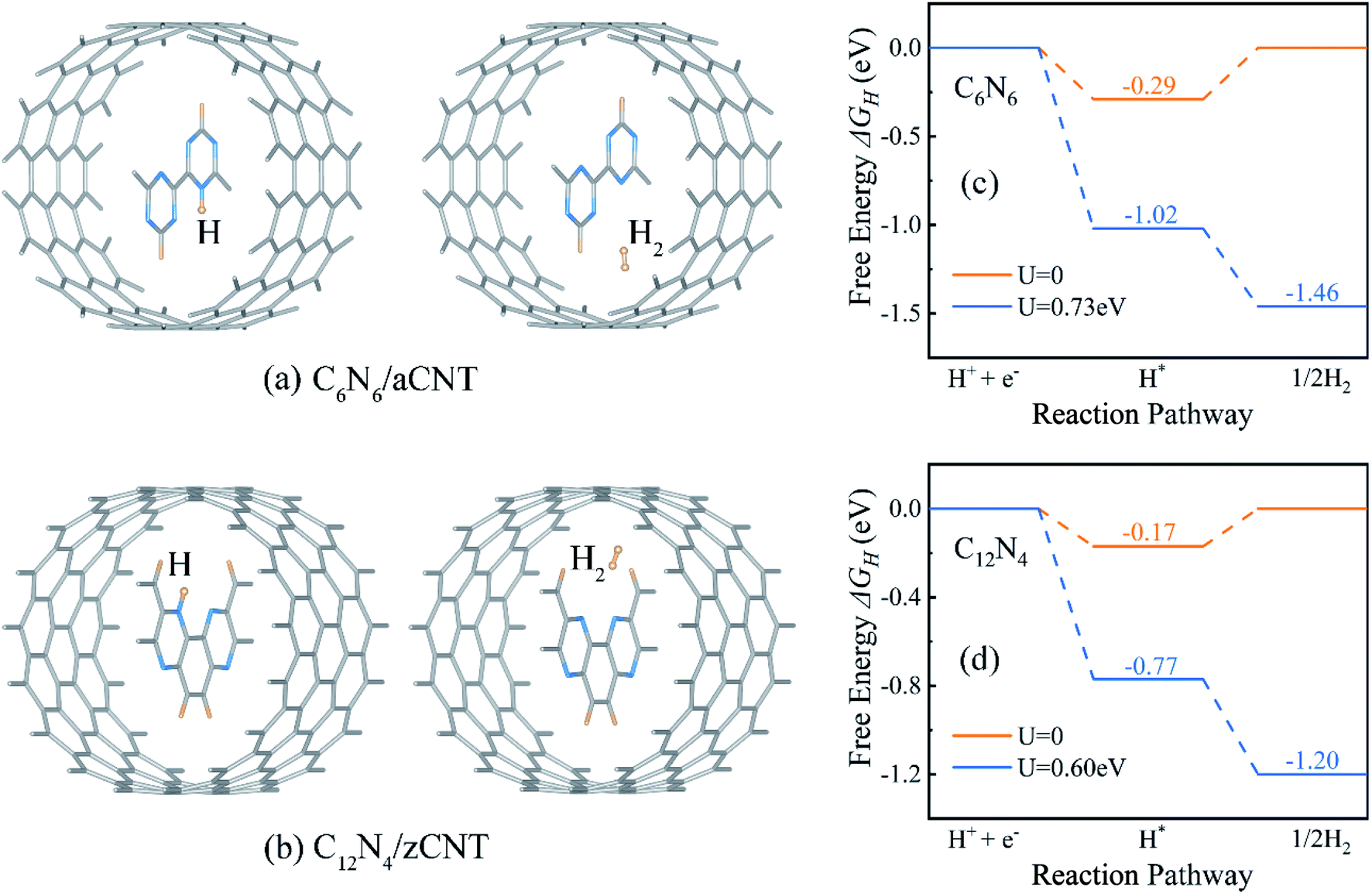 | ||
| Fig. 4 Optimized configurations of (a) C6N6/aCNT and (b) C12N4/zCNT structures with adsorption of one H atom (left) and one H2 molecule (right). The HER Gibbs free energy profile of (c) C6N6 and (d) C12N4. U = 0.73 V and U = 0.60 V are potentials provided by photo-generated electrons and applied on C6N6 and C12N4, respectively. | ||
Since HER occurred on CNNWs, we calculated HER performance on CNNWs to prove the feasibility of HER reaction on CNNW. Fig. 4c and d showed the HER performance of C6N6 and C12N4. Generally, the overall HER pathway is a two-electron process with one adsorbed intermediate H*. The activity of HER depends greatly on the Gibbs free-energy of this adsorbed intermediate, |ΔGH*|. The binding between H* and catalyst can't be too strong or too weak, in other words, the smaller the |ΔGH*| value, the higher the HER performance. Notably, the calculated ΔGH* is −0.29 eV for C6N6 and −0.17 eV for C12N4, corresponding to low overpotentials (η = −0.29 V for C6N6 and η = −0.17 V for C12N4). Because the Pt crystal is the widely-used efficiently commercial HER electrocatalyst, we calculated the overpotential of the Pt(111) surface using the same method for comparison. As a result, the HER overpotential of the precious Pt catalysts with the value of −0.12 V is very close to that of the CNNWs. Notably, the |ΔGH*| values are lower than the potentials of the photo-generated energetic electrons in the CNNWs, 0.73(0.60) V and 0.51(0.34) V respectively for isolated C6N6 (C12N4) and C6N6 (C12N4) in core–shell structures, which are defined as the energy difference between the CBM and the hydrogen reduction potential. Therefore, under the potentials provided by photo-generated energetic electrons, for both C6N6 and C12N4, the two steps of HER are downhill in the free energy profiles, and thus can proceed spontaneously under light irradiation.
Finally, H2 molecules stored inside the CNTs by physically blocking the penetration of H2. CNTs have been widely studied for hydrogen storage, the store rates for the CNTs ranged from 0.01 wt% to 10 wt%, and CNTs would not have large deformations caused by hydrogen storages.54
Notably, the honeycomb network of carbon atoms (graphene and CNTs) allows the penetration of protons,31,40 and blocks O2/H2 and other functional groups. Therefore, the two half reaction of water splitting, HER and OER, take place inside and outside of CNTs, respectively. The produced H2 molecules are naturally separated from O2 and stably confined in CNTs. In this way, unnecessary reversible reaction in water splitting can be avoided and complete H2 reduction process can be realized.
Conclusions
In summary, on the basis of density functional theory (DFT), we proposed one-dimensional core–shell CNNW/CNT structures to achieve efficient light absorption, photo-generated carrier separation, photocatalytic water splitting to generate hydrogen molecules and safe capsule hydrogen storage in a single system. It generates holes and electrons to be distributed respectively on active sites of the CNTs and the CNNWs by harvesting visible and ultraviolet light. Protons penetrate the wall of CNTs and HER takes place in the interior of CNT in the presence of CNNWs. The CNNWs exhibit excellent HER activity with the overpotentials of −0.29 V (for C6N6) and −0.17 V (for C12N4), which can be overcome by the potentials of the photo-generated energetic electrons in the CNNWs. The produced hydrogen molecules are naturally separated and stably stored inside the CNTs. These results are expected to pave a new feasible way for the production and storage of hydrogen molecules in CNTs.Conflicts of interest
There are no conflicts to declare.Acknowledgements
This study is supported by the National Natural Science Foundation of China (21833004), Basic Research Project of Natural Science Foundation of Shandong Province (ZR2018ZB0751), and the Taishan Scholar Program of Shandong Province.References
- K. Maeda and K. Domen, J. Phys. Chem. Lett., 2010, 1, 2655–2661 CrossRef CAS.
- F. X. Xiao, J. W. Miao, H. B. Tao, S. F. Hung, H. Y. Wang, H. B. Yang, J. Z. Chen, R. Chen and B. Liu, Small, 2015, 11, 2115–2131 CrossRef CAS PubMed.
- Z. Wang, C. Li and K. Domen, Chem. Soc. Rev., 2019, 48, 2109–2125 RSC.
- C. Gao, T. Wei, Y. Zhang, X. Song, Y. Huan, H. Liu, M. Zhao, J. Yu and X. Chen, Adv. Mater., 2019, 31, 1806596 CrossRef PubMed.
- S. Ida, N. Kim, E. Ertekin, S. Takenaka and T. Ishihara, J. Am. Chem. Soc., 2015, 137, 239–244 CrossRef CAS PubMed.
- Y. Xu, W. Zhao, R. Xu, Y. Shi and B. Zhang, Chem. Commun., 2013, 49, 9803–9805 RSC.
- R. Peng, L. Liang, Z. D. Hood, A. Boulesbaa, A. Puretzky, A. V. Ievlev, J. Come, O. S. Ovchinnikova, H. Wang, C. Ma, M. Chi, B. G. Sumpter and Z. Wu, ACS Catal., 2016, 6, 6723–6729 CrossRef CAS.
- C. Huang, C. Chen, M. Zhang, L. Lin, X. Ye, S. Lin, M. Antonietti and X. Wang, Nat. Commun., 2015, 6, 7698 CrossRef PubMed.
- G. Liao, X. Tao and B. Fang, Matter, 2022, 5, 377–379 CrossRef CAS.
- P. Shandilya, S. Sambyal, R. Sharma, P. Mandyal and B. Fang, J. Hazard. Mater., 2022, 428, 128218 CrossRef CAS PubMed.
- C. Li, G. Liao and B. Fang, Chem Catal., 2022, 2, 238–241 CrossRef.
- G. Liao, C. Li, S.-Y. Liu, B. Fang and H. Yang, Trends Chem., 2022, 4, 111–127 CrossRef CAS.
- Q. X. Liu, C. M. Zeng, Z. H. Xie, L. H. Ai, Y. Y. Liu, Q. Zhou, J. Jiang, H. Q. Sun and S. B. Wang, Appl. Catal., B, 2019, 254, 443–451 CrossRef CAS.
- M. Z. Rahman, K. Davey and S.-Z. Qiao, J. Mater. Chem. A, 2018, 6, 1305–1322 RSC.
- Y. Zheng, Y. Jiao, Y. Zhu, Q. Cai, A. Vasileff, L. H. Li, Y. Han, Y. Chen and S.-Z. Qiao, J. Am. Chem. Soc., 2017, 139, 3336–3339 CrossRef CAS PubMed.
- W. Che, W. R. Cheng, T. Yao, F. M. Tang, W. Liu, H. Su, Y. Y. Huang, Q. H. Liu, J. K. Liu, F. C. Hu, Z. Y. Pan, Z. H. Sun and S. Q. Wei, J. Am. Chem. Soc., 2017, 139, 3021–3026 CrossRef CAS PubMed.
- Q. Han, B. Wang, J. Gao and L. Qu, Angew. Chem., Int. Ed., 2016, 55, 10849–10853 CrossRef CAS PubMed.
- B. Zhu, B. Cheng, L. Zhang and J. Yu, Carbon Energy, 2019, 1, 32–56 CrossRef CAS.
- W. Pei, S. Zhou, Y. Bai and J. Zhao, Carbon, 2018, 133, 260–266 CrossRef CAS.
- S. Zhou, X. Yang, W. Pei, N. Liu and J. Zhao, Nanoscale, 2018, 10, 10876–10883 RSC.
- X. Wang, K. Maeda, A. Thomas, K. Takanabe, G. Xin, J. M. Carlsson, K. Domen and M. Antonietti, Nat. Mater., 2009, 8, 76–80 CrossRef CAS PubMed.
- P. Niu, L. Zhang, G. Liu and H.-M. Cheng, Adv. Funct. Mater., 2012, 22, 4763–4770 CrossRef CAS.
- F. Chang, Y. Xie, C. Li, J. Chen, J. Luo, X. Hu and J. Shen, Appl. Surf. Sci., 2013, 280, 967–974 CrossRef CAS.
- G. Liao, Y. Gong, L. Zhang, H. Gao, G.-J. Yang and B. Fang, Energy Environ. Sci., 2019, 12, 2080–2147 RSC.
- F. Chang, J. Zhang, Y. Xie, J. Chen, C. Li, J. Wang, J. Luo, B. Deng and X. Hu, Appl. Surf. Sci., 2014, 311, 574–581 CrossRef CAS.
- Y. Liu, S. Shen, Z. Li, D. Ma, G. Xu and B. Fang, Mater. Charact., 2021, 174, 111031 CrossRef CAS.
- Y. Liu, G. Xu, D. Ma, Z. Li, Z. Yan, A. Xu, W. Zhong and B. Fang, J. Cleaner Prod., 2021, 328, 129745 CrossRef CAS.
- G. Liao, C. Li, X. Li and B. Fang, Cell Rep. Phys. Sci., 2021, 2, 100355 CrossRef CAS.
- G. O. Hartley and N. Martsinovich, Faraday Discuss., 2021, 227, 341–358 RSC.
- L. Yang, X. Y. Li, G. Z. Zhang, P. Cui, X. J. Wang, X. Jiang, J. Zhao, Y. Luo and J. Jiang, Nat. Commun., 2017, 8, 16049 CrossRef CAS PubMed.
- S. Hu, M. Lozada-Hidalgo, F. C. Wang, A. Mishchenko, F. Schedin, R. R. Nair, E. W. Hill, D. W. Boukhvalov, M. I. Katsnelson, R. A. W. Dryfe, I. V. Grigorieva, H. A. Wu and A. K. Geim, Nature, 2014, 516, 227–230 CrossRef CAS PubMed.
- X. Hong, J. Kim, S.-F. Shi, Y. Zhang, C. Jin, Y. Sun, S. Tongay, J. Wu, Y. Zhang and F. Wang, Nat. Nanotechnol., 2014, 9, 682–686 CrossRef CAS PubMed.
- X. Zhu, N. R. Monahan, Z. Gong, H. Zhu, K. W. Williams and C. A. Nelson, J. Am. Chem. Soc., 2015, 137, 8313–8320 CrossRef CAS PubMed.
- H. Chen and D. S. Sholl, J. Am. Chem. Soc., 2004, 126, 7778–7779 CrossRef CAS PubMed.
- A. L. Elías, J. A. Rodríguez-Manzo, M. R. McCartney, D. Golberg, A. Zamudio, S. E. Baltazar, F. López-Urías, E. Muñoz-Sandoval, L. Gu, C. C. Tang, D. J. Smith, Y. Bando, H. Terrones and M. Terrones, Nano Lett., 2005, 5, 467–472 CrossRef PubMed.
- R. Kitaura, N. Imazu, K. Kobayashi and H. Shinohara, Nano Lett., 2008, 8, 693–699 CrossRef CAS PubMed.
- X. P. Gao, Y. Zhang, X. Chen, G. L. Pan, J. Yan, F. Wu, H. T. Yuan and D. Y. Song, Carbon, 2004, 42, 47–52 CrossRef CAS.
- Z. B. He, C. S. Lee, J. L. Maurice, D. Pribat, P. Haghi-Ashtiani and C. S. Cojocaru, Carbon, 2011, 49, 4710–4718 CrossRef CAS.
- H. Dai, E. W. Wong, Y. Z. Lu, S. Fan and C. M. Lieber, Nature, 1995, 375, 769–772 CrossRef CAS.
- L. Yang, X. Li, Y. Huang, S. Feng, X. Wang, X. Jiang, X. Li, J. Zhao, Y. Luo, G. Zhang and J. Jiang, J. Phys. Chem. Lett., 2019, 10, 3739–3743 CrossRef CAS PubMed.
- G. Kresse and J. Furthmuller, Phys. Rev. B, 1996, 54, 11169–11186 CrossRef CAS PubMed.
- P. E. Blochl, Phys. Rev. B, 1994, 50, 17953–17979 CrossRef PubMed.
- J. P. Perdew, J. A. Chevary, S. H. Vosko, K. A. Jackson, M. R. Pederson, D. J. Singh and C. Fiolhais, Phys. Rev. B, 1992, 46, 6671–6687 CrossRef CAS PubMed.
- J. P. Perdew, K. Burke and M. Ernzerhof, Phys. Rev. Lett., 1996, 77, 3865–3868 CrossRef CAS PubMed.
- J. Heyd, G. E. Scuseria and M. Ernzerhof, J. Chem. Phys., 2003, 118, 8207–8215 CrossRef CAS.
- S. Grimme, J. Comput. Chem., 2006, 27, 1787–1799 CrossRef CAS PubMed.
- H. J. Monkhorst and J. D. Pack, Phys. Rev. B, 1976, 13, 5188–5192 CrossRef.
- G. Henkelman, A. Arnaldsson and H. Jónsson, Comput. Mater. Sci., 2006, 36, 354–360 CrossRef.
- G. Henkelman and H. Jónsson, J. Chem. Phys., 2000, 113, 9978–9985 CrossRef CAS.
- Q. Zheng, W. Chu, C. Zhao, L. Zhang, H. Guo, Y. Wang, X. Jiang and J. Zhao, Wiley Interdiscip. Rev.: Comput. Mol. Sci., 2019, 9, e1411 CAS.
- J. K. Norskov, J. Rossmeisl, A. Logadottir, L. Lindqvist, J. R. Kitchin, T. Bligaard and H. Jonsson, J. Phys. Chem. B, 2004, 108, 17886–17892 CrossRef CAS.
- D. Xiang, C. Han, J. Wu, S. Zhong, Y. Liu, J. Lin, X.-A. Zhang, W. Ping Hu, B. Özyilmaz, A. H. C. Neto, A. T. S. Wee and W. Chen, Nat. Commun., 2015, 6, 6485 CrossRef CAS PubMed.
- W. Pei, S. Zhou, J. Zhao, Y. Du and S. X. Dou, J. Mater. Chem. A, 2020, 8, 20570–20580 RSC.
- S. V. Sawant, S. Banerjee, A. W. Patwardhan, J. B. Joshi and K. Dasgupta, Int. J. Hydrogen Energy, 2019, 44, 18193–18204 CrossRef CAS.
Footnote |
| † Electronic supplementary information (ESI) available. See https://doi.org/10.1039/d2ra02349k |
| This journal is © The Royal Society of Chemistry 2022 |