
 Open Access Article
 This Open Access Article is licensed under a
 Creative Commons Attribution 3.0 Unported Licence
Influence of Co2+, Cu2+, Ni2+, Zn2+, and Ga3+ on the iron-based trimetallic layered double hydroxides for water oxidation†
Jesus David Yong a,
Ricardo Valdez*b,
Miguel Ángel Armentac,
Noé Arjonad,
Georgina Pina-Luisb and
Amelia Olivas*a
a,
Ricardo Valdez*b,
Miguel Ángel Armentac,
Noé Arjonad,
Georgina Pina-Luisb and
Amelia Olivas*a
aCentro de Nanociencias y Nanotecnología – UNAM, Km. 107 Carr. Tijuana-Ensenada, C.P. 22860, Ensenada, BC, Mexico. E-mail: aolivas@cnyn.unam.mx
bTecnológico Nacional de México/Instituto Tecnológico de Tijuana, Centro de Graduados e Investigación en Química, Blvd. Alberto Limón Padilla S/N, Mesa de Otay, C.P. 22500, Tijuana, BC, Mexico. E-mail: ricardo.valdez@tectijuana.edu.mx
cUniversidad Estatal de Sonora, Departamento de Ingeniería en Geociencias, Av. Niños Héroes, San Javier, C.P. 84160, Magdalena de Kino, Son, Mexico
dCentro de Investigación y Desarrollo Tecnológico en Electroquímica, Parque Tecnológico Querétaro, Sanfandila, C.P. 76703, Pedro Escobedo, Qro, Mexico
First published on 8th June 2022
Abstract
In this work, we synthesized five novel iron-based trimetallic layered double hydroxides (LDHs) by the urea-assisted co-precipitation method for the electrocatalytic water oxidation reaction (WOR). In particular, the synthesized electrocatalysts were labeled CoCuFe-LDH, ZnNiFe-LDH, ZnCoFe-LDH, ZnCuFe-LDH, and CoGaFe-LDH. The electrocatalysts were thoroughly characterized by means of Ultraviolet-visible spectroscopy (UV-Vis), N2 adsorption/desorption, and X-ray photoelectron spectroscopy (XPS). We analyzed the changes in the electronic structures, changes in the surface area, and the oxygen vacancies, respectively. X-ray diffraction (XRD) and transmission electron microscopy (TEM) showed that the materials had the hydrotalcite-like structure typical of LDHs. Electrochemical results indicated that the best electrocatalyst was the CoGaFe-LDH achieving an overpotential of 369.9 mV at 10 mA cm−2 and a Tafel slope of 64.8 mV dec−1 in alkaline conditions (KOH 1 M). Additionally, this material displayed a charge transfer resistance (Rct) of 30.1 Ω cm2. Electrochemical measurements indicated that the materials containing Zn2+ exhibit low kinetics; whilst materials with Co2+ or Ga3+ yield the best performances. The catalytic activity of the CoGaFe-LDH can be attributed to the decrease of the Rct caused by electronic effects due to the addition of the Ga3+, lowering the thermodynamic barriers and thus enhancing the electron transfer. This work opens the door for a new approach to design efficient multimetallic catalysts based on the transition metals for WOR.
Introduction
The demand for energy increases continuously as technology, quality of life, and population density increases; for this reason, it is necessary to find viable ways to produce renewable and environmentally friendly fuels.1–3 Molecular hydrogen is a great alternative to accomplish the energetic demand because of its high calorific value, which can be produced by electro- and photochemical water splitting.1,3–5 Water oxidation reaction (WOR) is crucial for the development of chemical energy generation through excitonic chemical conversion devices like artificial photosynthesis systems (PS).2,6 The challenge to achieve a scalable WOR is to overcome the high applied potential due to the nature of this multi-electron reaction:| 2H2O → O2 + 4H+ + 4e− |
Precious metals like Ir or Ru and their oxides have been reported to be well-known active catalysts for the WOR in acid conditions, but these elements are expensive to be easily scalable.8–10 Moreover, several materials like perovskites, spinels, layered double hydroxides (LDHs), among others, have been reported for affordable WOR electrocatalysis.4,11–14 First-row transition metals like Fe, Co, Ni, Mn, Zn, and Cu have also been evaluated as cheaper catalysts and co-catalysts (more abundant on earth's surface) than precious metals for either photosystem of type 1 or 2.4,5,7,15–17
NiFe and CoFe LDHs have been engineered for enhancing the electrocatalytic activity and they are some of the most active catalysts for WOR based on transition metals.18–20 Nevertheless, few mechanisms or strategies have been proposed to modulate their electronic structure. Recently, Wang et al., proposed that the incorporation of transition metals with 5dn electronic configuration could modulate the electronic structure of materials based on 3d metals,21 however, they applied this only to the case of iridium which is a well-known catalyst for water splitting. Some studies indicate that trimetallic LDHs exhibit a higher performance than bimetallic LDHs. In particular, the electrocatalytic activity of CoNiFe-LDHs and CoFeV-LDHs of these materials were better than the bimetallic ones.22
One of the catalyst design strategies is to be guided by the existing ones and then varying the active species by doping, changing the synthesis method, and modifying the crystal structure or the catalyst morphology.23 The first parameter aims to modify the electronic structure of the catalysts by adding other atoms or ions. The second one refers to increase the amount of available active sites where the reaction will take place. The last one is seeking to change the energies of the active sites through modifying their molecular geometry or coordination.23–25
Lately, a novel strategy in the catalyst design is the incorporation and increasing of oxygen vacancies. In recent times, research groups have been demonstrated that the oxygen vacancies enhanced the water oxidation catalysis. For instance, Wang et al., synthesized an exfoliated nitrogen-doped oxygen vacancy-rich NiFe-LDH for enhancing the WOR.26 Furthermore, Wang et al., synthesized a LDH with oxygen vacancies grown on carbon nanotubes for efficient WOR.27
To the best of our knowledge, there are only a few reports related to the synthesis of catalysts based on chemical properties such as ionic radius, electron affinity, or energy of the orbitals involved in the electron transfer.28,29 Hence, it is imperative to develop new strategies for designing catalysts based on the concepts already mentioned.
Here, we propose a new strategy in the design of novel trimetallic LDHs based on iron by applying fundamental concepts like ionic radius, coordination number, spin state, and crystal field effects, relevant to improve the catalyst performance towards WOR. We synthesized a series of new iron-based trimetallic LDHs by the urea-assisted co-precipitation method and evaluated them in the electrocatalytic WOR. Moreover, we studied the UV-vis data, the specific surface area, and the XPS spectra of these materials to monitor the changes in their electronic structures, changes in the surface area, and the number of oxygen vacancies (Ov) respectively, aiming remarkable improvement in water oxidation electrocatalysis.
Experimental section
Materials
All chemical reagents were analytical grade and supplied by Sigma Aldrich. They were used without further purification. Deionized water, Fe(NO3)3·9H2O (purity ≥ 99.95%), Co(NO3)2·6H2O (purity ≥ 98%), Ni(NO3)2·6H2O (purity ≥ 98.5%), Cu(NO3)2·3H2O(purity ≥ 98%), Zn(NO3)2·6H2O, and Ga(NO3)3·xH2O (purity ≥ 98%) were used in the LDHs synthesis. The main text of the article should appear here with headings as appropriate.Synthesis of trimetallic LDHs
The trimetallic LDHs were synthesized through a slightly modified urea-assisted co-precipitation method.17 Typically, in a two-neck flask 100 mmol of urea, 10 mmol of divalent metals, and 4.28 mmol of trivalent metals (trivalent metal molar fraction = 0.33) were dissolved in 100 mL of distilled water. The homogeneous solution was heated at 90 °C for 8 h with moderated magnetic stirring. The resulting solution had a pH of ∼9 and was aged for 13 h at 65 °C. Subsequently, the slurries (∼1.2 g) were recovered by decantation and then the products were washed with distilled water and centrifuged 3 times at 5000 rpm for 30 min. Finally, the synthesized LDH materials were dried in a Lindberg Blue M programmable oven at 100 °C for 16 h.Physicochemical characterization of LDHs
X-ray powder diffraction (XRD) patterns were recorded on a D2 PHASER diffractometer using Cu Kα (λ = 1.54056 Å) radiation. The analyses were carried out in a Bragg–Brentano configuration from 10 to 80° in 2θ with a step size 0.02° and time of step of 0.5 s, with an operating voltage and current of 40 kV and 30 mA. N2 adsorption/desorption measurements were performed using a Micromeritics model Tristar II equipment at −196 °C. The specific surface area was calculated by the Brunauer–Emmett–Teller (BET) method, and the pore volume and diameter through the Barrett, Joyner, and Halenda (BJH) method. The samples were degassed overnight to 110 °C before the measurements.Fourier transform infrared (FT-IR) spectra were obtained by a Bruker Tensor 27 spectrometer from 350 to 4000 cm−1 for 50 scans with a spectral resolution of 6 cm−1. The FT-IR spectra were corrected to the blank (KBr), atmospheric noise, as well as shifted to the baseline. Thermogravimetric analyses (TGA) were carried out using a TA SDT-Q600 Instruments equipment. In a typical TGA analysis, ∼3 mg of catalyst were placed on alumina pans and heated from 30 to 830 °C using an airflow of 100 mL min−1 at a temperature ramp of 10 °C min−1.
Ultraviolet-visible (UV-vis) studies were carried out with an Agilent Technologies spectrophotometer (Cary 5000 UV-Vis-NIR) that uses a tungsten lamp as the visible and infrared light source and a deuterium lamp as the ultraviolet light source. Furthermore, the spectrophotometer counts with an integration sphere made with a reference material “spectralon”. UV-vis spectra were recorded from 200 to 1100 nm in the reflectance mode and corrected to a blank (MgO) and baseline.
X-ray photoelectron spectroscopy (XPS) measurements were performed in a SPECS PHI-548 spectrometer. The instrument is equipped with a monochromatic source consisting of an aluminum anode (Kα = 1486.6 eV, 300 W). Measurements were obtained for 4 cycles at an energy pass of 150 eV in the case of the survey and 16 cycles at an energy pass of 50 eV for high-resolution spectra. The XPS spectra were calibrated by adjusting the C1s peak of the adventitious carbon for charging effects at a binding energy of 284.8 eV.
Energy-dispersive X-ray spectroscopy (EDS) analyses were performed through a JEOL JIB-4500 microscope. The electron gun was lanthanum hexaboride (LaB6) and operated at an accelerating voltage of 200 kV.
Transmission electron microscopy (TEM), selected area electron diffraction (SAED), and chemical mapping analyses were carried out using a JEOL JEM-2100F (STEM) microscope. This microscope is equipped with a field emission-Schottky type electron gun operated at an acceleration voltage of 200 kV. The samples were dispersed in isopropanol by sonication for at least 30 min, and then a drop of the solution was dropped onto a 300 mesh copper grid covered with an amorphous carbon film to further use.
Electrochemical measurements
Electrochemical measurements were performed at room conditions using a three electrodes configuration; a glassy carbon electrode (GCE) was used as the working electrode, a saturated calomel electrode (SCE) as a reference electrode, and a graphite electrode as the counter electrode. The electrocatalytic evaluation was carried out in aqueous 1 M KOH solution (pH = 14) as electrolyte. From LDHs, catalytic inks were prepared, afterward, those inks were drop-casted on the GCEs, to form chemically-modified electrodes. Before the preparation of the composite electrodes, the GCEs were polished until mirror finish. The preparation of the catalytic inks consisted of mixing 3 mg of catalyst, a 77% V/V of 5 wt% isopropanol-Nafion® solution, and 0.5 mg of Vulcan® carbon per mg of catalyst, which was sonicated for at least 30 min. Then, the ink was added to the GCE and allowed to dry for at least 1 h at room conditions to give a final catalyst loading of ∼0.2 mg cm−2.LSV measurements were performed from 100 mV to 800 mV at a sweep rate of 5 mV s−1. The potentials measured against the SCE were converted to the scale of the reversible hydrogen electrode (RHE) using the eqn (1):30
| ERHE = ESCE + 0.241 + 0.059 × pH (V) | (1) |
On the other hand, electrochemical cyclic voltammetry (CV) tests were carried out at ±50 mV from the open circuit potential to ensure that the measurement was recorded in the non-faradaic region.8 Furthermore, EIS analyses were performed at a potential of 1.64 V vs. RHE due to the reaction is occurring at this potential, with a disturbance frequency of 100 kHz to 1 Hz and an amplitude of 10 mV. We chose that potential value in EIS measurements to ensure the reaction takes place in all catalysts. The WOR stability test of the CoGaFe-LDH and CoCuFe-LDH were carried out by chronoamperometry at a potential to achieve 10 mA cm−2 using a GCE-rotating disk electrode (RDE) with a geometrical area of 0.0707 cm2 at 1600 rpm. LSV and CV measurements were obtained through a Digi-Ivy DY2300 potentiostat, the EIS curves were carried out using a CH Instruments 920D potentiostat, and chronoamperometry measurements were performed using a Metrohm Autolab potentiostat.
Results and discussion
Structural determination and chemical composition
The crystalline structures of the synthesized materials were determined through XRD (Fig. 1). X-ray patterns of all materials showed hydrotalcite characteristic diffractions (JCPDS: 41-1428) at 2θ of 13° (003), 24° (006), 34° (101), 36° (012), 39° (018), and 60° (110). The most intense peak (003) is shifted approximately 1° to the right in most of the patterns. 2θ shifts are attributed to the expansion or contraction of the crystal lattice, according to Bragg's law, due to structural defects or ionic substitutions within it. LDH patterns of the synthesized catalysts were compared with other crystallographic reference patterns that matched more closely than the hydrotalcite one (Table 1). The only material that showed a predominant phase other than hydrotalcite was the one labeled as CoCuFe-LDH which exhibited the presence of copper nitrate hydroxide (JCPDS: 45-0594). The lack of the peak corresponding to the (006) plane in ZnNiFe-LDH could be due to the molar ratio (>0.33) between cations causing the (006) plane intensity decreases.31 In the ZnCoFe-LDH, the low crystallinity is attributed to the concentration of trivalent metal compared to that of divalent metal (as will be seen later in the EDS analyses), which exceeds the concentration limit that an LDH can handle before deforming its structure.32 | ||
| Fig. 1 X-ray diffraction patterns corresponding to the synthesized LDHs. | ||
| Material | JCPDS | BET area (m2 g−1) | Pore volume (cm3 g−1) | Pore size (nm) |
|---|---|---|---|---|
| CoCuFe-LDH | 45-0594 | 36.5 | 0.0813 | 8.74 |
| ZnNiFe-LDH | 51-046333 | 92.9 | 0.1679 | 7.26 |
| ZnCoFe-LDH | — | 72.2 | 0.1667 | 8.63 |
| ZnCuFe-LDH | 38-0154 | 72.4 | 0.1121 | 5.64 |
| CoGaFe-LDH | 50-023534 | 91.7 | 0.1071 | 4.84 |
We observed type IV isotherms showing an H3 hysteresis loop in all the synthesized materials, which are characteristic of mesoporous materials (Fig. S1†). This type of isotherm and hysteresis loop do not present any limiting adsorption at high relative pressure, which is observed in aggregates of plate-like particles such as that of the LDHs.33,34
Table 1 also shows the textural properties of the LDHs synthesized. Here, we observed that the specific surface area decreases as: ZnNiFe-LDH > CoGaFe-LDH > ZnCuFe-LDH > ZnCoFe-LDH > CoCuFe-LDH. Moreover, we observed that the pore size is ranging from 4.84 to 8.74 nm which, again, agrees with the definition of mesoporous materials.33
Interlaminar anions of the LDHs were identified by vibrational (FT-IR) spectroscopy. Fig. 2a displays the CoGaFe-LDH spectrum (see Fig. S2† for the FT-IR spectra of all the synthesized LDHs). The broad and intense bands observed between 3570–3390 cm−1 and the band centered around 1620 cm−1 are characteristic of the hydroxyl stretching modes on the LDH lattice and the bending modes of the interlaminar H2O molecules, respectively. The band around 2200 cm−1 is attributed to the presence of isocyanate anions from the decomposition of urea (eqn (2) and (3)), which decomposes at high temperatures to produce isocyanate and ammonium ions according to the following reaction:
| CO(NH2)2 → NH4CNO | (2) |
| NH4CNO + 2H2O → (NH4)2CO3 | (3) |
 | ||
| Fig. 2 (a) FT-IR spectrum of CoGaFe-LDH. (b) Thermograms of the synthesized LDHs. (c) EDS spectrum of CoGaFe-LDH. | ||
The intense and sharp band at ∼1380 cm−1 is characteristic of nitrate ions (NO3−) that come from the metal precursors used during synthesis. The bands at 1050 (ν1) and 875 (ν2) cm−1 are ascribed to the deformation modes of CO32− ions. The ν3 vibration band at ∼1415 cm−1 is not obvious, because it may be hidden by other more intense bands such as the NO3− one. However, the band at ∼1050 cm−1, which has been identified as characteristic of CO32− ions, was observed clearly in most of the LDH except for the CoGaFe, where the NO3− seems to be the dominant species in the interlaminar region.35 These CO32− species come from the dissolution of atmospheric CO2 into the aqueous solution, as well as, from the urea decomposition reaction. The vibrations in the fingerprint area, in the wavenumbers < 800 cm−1, are ascribed to the distinct vibrations of the M–OH bonds.
Thermogravimetric measurements were performed to confirm the weight loss stages corresponding to the phase change from LDHs to mixed oxides (Fig. 2b). We observed that a dehydration process of the materials occurred in 2 stages (black arrows); the first one between ∼30 and 200 °C is due to weakly bound water, such as, water within the pores between LDH agglomerates. The second one is located between 200 and 350 °C and attributed to the bound water in the interlaminar region of LDHs.32 The weight losses at higher temperatures were attributed to the decomposition of the interlaminar anions (CO32− and NO3−) and to the dehydroxylation process that leads to the mixed oxide formation. Furthermore, we observed that the thermal stability of the materials follows the order: ZnCuFe-LDH > ZnNiFe-LDH > ZnCoFe-LDH > CoGaFe-LDH > CoCuFe-LDH, which indicates that the Zn2+ is playing a significant role as a thermal stabilizer while Co2+ has the opposite effect. The ZnCoFe-LDH thermogram does not show the typical two-step weight losses as the other materials, which is in agreement with the poor crystallinity observed in the diffractogram of this mate-rial. The EDS spectrum of the CoGaFe-LDH material is shown in Fig. 2c. We confirmed through EDS analyses that the cations were incorporated into the LDH as observed in Fig. 2c and S3.† In the spectra we noted a small peak of N, this peak is due to the presence of the interlaminar NO3− anions. The low crystallinity of the ZnCoFe-LDH displayed in the diffractogram is due to the greater amount of Fe compared to that of Zn and Co, as shown in Table S2 and S3.† It is well-known that the LDHs allow only a 0.33 molar fraction of trivalent cations in comparison to all other cations present in a given LDH.36
UV-vis spectra of the synthesized LDHs are shown in Fig. 3a. We noted that all materials have a broad band from ∼200 to 570 nm, which is ascribed to several transitions that depend on the metal composition of the catalyst (Fig. S4†).37 In the Co2+ containing materials, the band at higher energy is attributed to 4T1g(F) → 4A2g(F) whereas the band at lower energy is assigned to 4T1g(F) → 4T1g(P) transitions.38 The CoCuFe-LDH material (Fig. 3b) has a wide absorption band ranging from 570 to 760 nm wavelengths with maximum absorption at ∼710 nm, this band is attributed to the 4T1g(F) → 4T1g(P) transition of Co2+.37 Additionally, these 3 bands are observed in all Co2+ containing materials as expected within a UV-vis spectrum, for a weak or moderately weak field octahedral material.38 The bands in the spectra should be shifted to higher or lower wavelengths if there are any metal cation that can shift the bands through an additional contribution from a transition to nearby energies, such as Cu2+ in the case of CoCuFe-LDH. In this case, we observed that the bands assigned to the Co2+ species shifted to lower energies because of the Cu2+ (5E2g → 5T2g) transition. This displacement toward lower energies could be due to the coulombic repulsion between electronic shields of Cu2+ and Co2+, which would make the electrons in these atoms have additional energy, consequently, further transitions would need less energy than those that do not have this repulsion effect. In the ZnNiFe-LDH spectrum showed in the Fig. S4,† we can observe 3 bands attributed to the Ni2+ electronic transitions 3A2g(F) → 3T2g(F), 3A2g(F) → 3T1g(F), and 3A2g(F) → 3T2g(P) in octahedral sites located from lower to higher wavelengths.38 Metals with d5 or d10 configuration do not show electronic transitions in weak or moderately weak fields (such as Fe3+ or Zn2+). For this reason, there are no bands assigned to Zn2+ or Fe3+ species. However, there are forbidden transitions by symmetry that can be “relaxed” and shoulders could appear due to these processes of violation or “relaxation” of the selection rules.38
 | ||
| Fig. 3 (a) UV-vis spectra of the LDHs. (b) UV-vis spectrum of CoCuFe-LDH and its electronic transitions. (c) Tauc plot of CoCuFe-LDH. (d) Band gaps of the LDHs. | ||
The complexity of UV-vis spectra, as in the case of ZnCuFe-LDH, may be due to effects such as Jahn–Teller type distortions (J–T) due to having cations with d5, d9, and d10 electronic configuration (Fe3+, Cu+, and Zn2+, respectively) within these materials. The first two electronic configurations are prone to octahedral distortions of this type (J–T), which would affect the crystallinity of the material. These observations are in agreement with the presence of other phases found in the CoCuFe-LDH material, as seen in XRD analyses. Fig. 3c shows the Tauc plot of the CoCuFe-LDH considering that the material presents a direct and allowed transition (see Fig. S5†).39,40 Besides, we observed that the curve of Fig. 3c has two absorption edges, which are attributed to different phases or different particle sizes, such as the CoCuFe-LDH. As seen in Fig. 3d, the Eg values from 1.45 to 2.49 eV indicate that the materials could have a potential application in semiconductor devices such as solar cells or in photocatalysis and photo-electrocatalysis.
The chemical state and composition on the surface of the LDHs were determined by XPS. In Fig. 4 are shown the XPS spectra of CoGaFe-LDH. Through the survey spectrum (Fig. 4a), the presence of the elements previously presented by EDS was confirmed, which were consistent with each other. The most intense photoemission peaks at 284.8 and 532.2 eV corresponding to the C1s and O1s peaks, respectively, as well as the photoemission lines Fe2p and Auger FeLMM at 711 and 781 eV, respectively, were identified in all materials (Fig. S6–S9†).
 | ||
| Fig. 4 XPS spectra of CoGaFe-LDH. (a) Survey spectrum of CoGaFe-LDH. (b) Ga high-resolution spectrum. (c) Fe high-resolution spectrum. (d) Co high-resolution spectrum. | ||
The main lines of photoemission and Auger peaks for the other metal components of the materials like Cu, Co, Ni, Zn, and Ga were identified in Fig. 4 and S6–S9† (Cu3s, Cu3p, CuLMM, Co2s, Co2p, Ni2p, NiLMM, Zn3p, ZnLMM, etc.). We identified the 2p3/2 peak and determined the spin–orbit splitting through the high-resolution spectra for the metal components of the samples presented in Fig. 4b–d, and in Fig. S6–S9.† The high-resolution spectra were meticulously analyzed to discard the presence of other chemical species.
Table S4† shows the position of the photoemission 2p3/2 peak in all materials. According to the literature, the Fe 2p3/2 peak located at 711.4 eV and the presence of two shake-up satellite peaks in all synthesized electrocatalysts suggest the presence of Fe3+ and Fe–OH bonding which appears in higher binding energies than Fe–O bond.41,42 Also, it is well-known that Cu2O appears at lower binding energies than 933 eV, instead, CuO appears shifted to higher binding energies.42,43 Also, 2p3/2 Cu peak in Cu(OH)2 is shifted to higher energies around 1.4 eV with respect to CuO.41 The values of 935.1 and 935.2 eV in Cu 2p3/2 peak of CoCuFe-LDH and ZnCuFe-LDH, respectively, suggest the presence of Cu2+ and the chemical species are bound with the OH− instead O2− anions. In Table S5† are presented the spin–orbit splitting values of the 2p doublets of all LDHs. Similarly, we carried out the same XPS analyses to determine the chemical state of all synthesized LDHs that turned out to be: Co2+, Ni2+, Zn2+, and Ga3+.44–46 These chemical species were those we expected according to the synthesis procedure and UV-vis analyses. Small differences between binding energies for the same species in different LDHs are attributed to different chemical environments. Table 2 shows the surface atomic percentages of the LDHs obtained by quantitative analysis. These results agree with those obtained by EDS.
| Material | %Ni | %Co | %Ga | %Cu | %Fe | %Zn |
|---|---|---|---|---|---|---|
| CoCuFe-LDH | — | 37.0 | — | 14.8 | 48.2 | — |
| ZnNiFe-LDH | 42.8 | — | — | — | 34.9 | 22.3 |
| ZnCoFe-LDH | — | 38.7 | — | — | 45.6 | 15.8 |
| ZnCuFe-LDH | — | — | — | 31.5 | 39.3 | 29.2 |
| CoGaFe-LDH | — | 61.2 | 7.4 | — | 31.4 | — |
Fig. 5 shows the O1s high-resolution XPS spectra of the materials synthesized. Through the O1s photoemission peak deconvolution, we observed 4 different O-bonded species for all materials, these peaks come from the oxygen atoms bonded to the cations of the LDHs (OI), the oxygen atoms bonded to the metal in the vicinity of an oxygen vacancy (OII), the oxygen belonging to the hydroxyl groups or the surface adsorbed oxygen (OIII), and the oxygen belonging to the water molecules (OIV) ranging from lowest to highest binding energies.26,27
 | ||
| Fig. 5 O1s XPS high-resolution deconvolved spectra of the materials synthesized. | ||
Table 3 displays the OI, OII, OIII, and OIV percentage of the materials synthesized. From here, we determined that the amount of oxygen vacancies in the materials follows the trend: ZnCoFe-LDH > CoCuFe-LDH > CoGaFe-LDH > ZnNiFe-LDH > ZnCuFe-LDH. The last four materials have a similar concentration of vacancies whereas the ZnCoFe-LDH presented around 15% more oxygen vacancies. In addition, Table S6† shows the position of the oxygen bands of the O1s deconvolved XPS spectra of the materials synthesized. The oxygen OI, OII, OIII, and OIV are located between 528.7–529.6 eV, 530.1–531.6 eV, 531.6–532.6 eV, and 533.2–533.7 eV, respectively. These differences arise from the different chemical compositions and environments in the materials.
| Material | OI (%) | OII (%) | OIII (%) | OIV (%) |
|---|---|---|---|---|
| CoCuFe-LDH | 10.64 | 29.98 | 47.86 | 11.52 |
| ZnNiFe-LDH | 10.68 | 24.71 | 50.22 | 14.39 |
| ZnCoFe-LDH | 20.08 | 43.65 | 26.69 | 9.58 |
| ZnCuFe-LDH | 15.35 | 23.95 | 52.88 | 7.83 |
| CoGaFe-LDH | 2.19 | 25.11 | 57.33 | 15.37 |
Morphological characterization
Fig. 6 shows the TEM and HRTEM images of CoGaFe-LDH. In Fig. 6a we see that the morphology for CoGaFe-LDH consists of nanosheets and nanoparticles. Additionally, we can see that the selected area electron diffraction (SAED) pattern shows a series of concentric rings, which indicates that the section is polycrystalline (inset of Fig. 6a). In Fig. 6b we measured a distance of 2.145 ± 0.025 Å, which agrees with the (018) plane of the hydrotalcite (JCPDS: 41-1428). The micrographs of the other materials are presented in the Fig. S10–S13.† We could also observe that Zn-containing materials have a very small amount of rich in cobalt nanorods and nanoparticles of LDHs (Fig. S12 and S13†). These results are in agreement with those of XRD in that both of them show characteristic planes of the hydrotalcite (JCPDS: 41-1428). Due to the last observation, we attributed the absence of nanorods and nanoparticles mainly to the presence of Zn2+. | ||
| Fig. 6 (a) TEM and selected area electron diffraction pattern of CoGaFe-LDH (b) HRTEM images of CoGaFe-LDH. | ||
Fig. 7 shows a dark-field TEM micrograph of the CoGaFe-LDH and its chemical mapping. We observed that CoGaFe-LDH is composed of Fe, Co, and Ga confirming that the metal elements were adequately incorporated in this material. Furthermore, it is observed that the nanorod on the right side of Fig. 7a, is composed mainly of Co (as seen in Fig. 7b), as long as the Ga and Fe are not observed (Fig. 7c and d). We also confirmed the morphology showed in the TEM and HRTEM micrographs, as well as we observed in all the materials, nanoparticles, and agglomerates of nanoparticles rich in iron (Fig. S14–S22†).
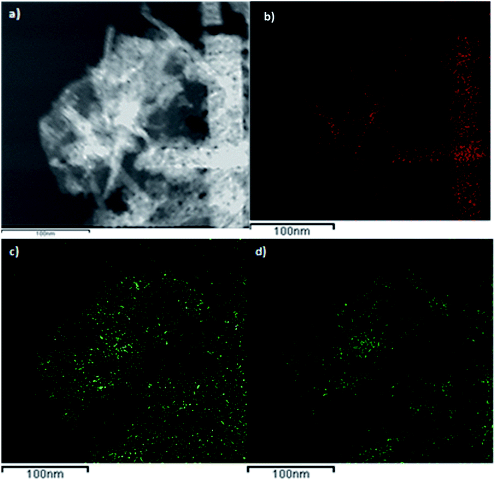 | ||
| Fig. 7 Chemical mapping of CoGaFe-LDH. (a) Dark-field micrograph. (b) Co, (c) Ga, and (d) Fe chemical mappings. | ||
Samples with higher cobalt loading promoted the formation of Co(OH)2 nanorods, as in the CoGaFe-LDH sample (Table S2†).
Electrochemical performance
Fig. 8 presents the electrocatalytic measurements that were carried out through LSV and CV. In Fig. 8a, the linear sweep voltammograms of the materials are shown. The overpotential “η” was calculated using the eqn (4):| η = ERHE − 1.23 V | (4) |
 | ||
| Fig. 8 (a) LSV measurements for the synthesized LDHs. (b) Tafel slopes, (c) and (d) double-layer capacitance measurements to determine the electrochemically active surface area for the CoGaFe-LDH catalyst. | ||
Fig. 8b shows the Tafel slopes derived from LSV measurements in Fig. 8a according to the Tafel equation (eqn (5)), by plotting the overpotential (or the potential) against the logarithm of the current density.
| η = b log(j) | (5) |
The capacitance of the electrical double layer was determined from CV recorded at the non-faradaic potential as the average of the absolute values of the slopes as shown in Fig. 8c and d. The capacitive current is related to the scan rate through eqn (6):
| Ic = νCdl | (6) |
Cyclic voltammograms, as well as the current vs. scan rate graphs for the other electrocatalysts are shown in Fig. S23 and S24.† Owing to there is a lack of an accurate and feasible method to measure the specific capacitance of the material, and knowing that the electrochemically active surface area (ECSA) is related to the specific capacitance by the eqn (7) and (8):
| SRF = Cdl/Cs | (7) |
| ECSA = SRF × Ag | (8) |
We also measured the electrode kinetics through the charge transfer resistance (Rct), which was obtained through Nyquist plots of the LDHs (Fig. 9a). From this plot, we observe the typical semicircles that are correlated with the Rct as follow; the smaller the semicircle the more active electrocatalytically the catalyst is. We noticed that the resistance due to the charge transfer in the materials follows the order: ZnNiFe-LDH > ZnCoFe-LDH > CoCuFe-LDH > CoGaFe-LDH. Hence, we concluded that Zn2+, Cu2+, or Ni2+ had higher Rct values than materials with Co2+ or Ga3+ which had lower Rct values. The lowest Rct was achieved by the CoGaFe-LDH reaching values as low as 30.1 Ω cm2. The decrease in the Rct in these materials could be due to the electronic effect of having a Ga3+ cation in octahedral coordination with OH− anions as we will see below.48
 | ||
| Fig. 9 (a) Nyquist plots for synthesized LDHs. (b) Chronoamperometric measurements of CoGaFe-LDH and CoCuFe-LDH. | ||
Table 4 show all electrocatalytic parameters calculated for the synthesized trimetallic LDHs. The values of Rct were calculated with the value measured by the Nyquist plot and then dividing by the ECSA. We noted that the materials with Zn2+ are the fewer actives, which suggests that Zn2+ could act as an inhibitor for this reaction. This could be due to Zn2+ has a closed electronic configuration, therefore it is more difficult to transfer the electronic charge, and the crystal field that this cation exerts in this coordination and oxidation state. On the other hand, the CoGaFe-LDH is the more active material which suggested that Ga3+ is the best promotor for WOR. In this case, despite the Ga3+ has the same electronic configuration than Zn2+, the Ga3+ has one positive charge more than the Zn2+. Also, the Ga3+ has an ionic radius equal to 76 pm when it has a coordination number of 6 whereas the Zn2+ in these conditions has an ionic radius to 88 pm leading to a different crystal field strength. We attributed this improvement in the electrocatalytic activity to the electronic properties of the Ga3+.
| Material | η at 10 mA cm−2 (mV) | Tafel slope (mV dec−1) | Cdl (μF cm−2) | ECSA (cm2) | Rct (Ω cm2) |
|---|---|---|---|---|---|
| CoCuFe-LDH | 415.5 | 91.9 | 38.8 | 0.0686 | 59.6 |
| ZnNiFe-LDH | 488.0 | 71.4 | 32.2 | 0.0570 | 482.0 |
| ZnCoFe-LDH | 413.2 | 64.9 | 34.6 | 0.0612 | 235.2 |
| ZnCuFe-LDH | 636.9 | 144.1 | 32.6 | 0.0577 | — |
| CoGaFe-LDH | 369.3 | 64.8 | 37.8 | 0.0669 | 30.1 |
Fig. 9b shows the stability tests during 10 h for the two most active materials (CoGaFe-LDH and CoCuFe-LDH). The CoGaFe-LDH exhibited an increase of 14% in current density in the first two hours owing to an electrochemical activation (see inset of Fig. 9b). At the end of the experiment, the current density of CoGaFe-LDH drops to 66% of its initial value. In contrast, the second most active material (CoCuFe-LDH) presented a gradual loss of current density, which lost 88% of its activity. The decrease in catalytic activity can be due to the detachment of the catalyst from the electrode as O2 evolves.49,50 Additional studies should be done to investigate the deactivation pathways of these materials.
Conclusions
In this work, we studied the electrocatalytic influence of Co2+, Cu2+, Ni2+, Zn2+, and Ga3+ on the ternary LDHs for WOR. UV-vis spectroscopy analyses showed that these materials absorb in the visible spectrum having Eg values from 1.45, to 2.45 eV for all the materials. Therefore, they could be applied to photocatalysis and photo-electrocatalysis fields. Through TGA analyses we notice that the Zn2+ is playing a significant role as a thermal stabilizer while Co2+ has the opposite effect. XPS O1s spectra of the materials showed that the amount of oxygen vacancies follows the order: ZnCoFe-LDH > CoCuFe-LDH > CoGaFe-LDH > ZnNiFe-LDH > ZnCuFe-LDH. Nevertheless, the electrocatalytic activity follows the order: CoGaFe-LDH > CoCuFe-LDH > ZnCoFe-LDH > ZnNiFe-LDH > ZnCuFe-LDH. However, despite the number of oxygen vacancies enhances the electrocatalytic activity toward the WOR, we suggested that this is not only the main factor for the enhancement of trimetallic LDHs for WOR. Also, the XPS and UV-vis studies reveal that CoGaFe-LDH material does not have mixed oxidation states for the same element, which excludes the possibility that the catalytic activity is due to the mixed oxidation state. Although CoGaFe-LDH exhibited lower specific surface area than that of ZnNiFe-LDH (Table 1), it showed better catalytic activity. Besides, the CoCuFe-LDH catalyst has the lowest specific surface area and is the second material more active among the synthesized samples.The above evidence the role of Ga3+ cation in enhancing the catalytic activity of the materials to improve the performance of these catalysts. The material that contains the highest amount of Fe on the surface (CoCuFe-LDH), is the second most active material, in the case of the material with the highest activity (CoGaFe-LDH), it is concluded that Ga3+ plays a role of promoter in this material. The Tafel plot analyses revealed that materials with Zn2+ and Cu2+ in their composition produce low kinetics whilst materials with Co2+ or Ga3+ in their composition yields better performance toward the WOR. The Rct and ECSA values obtained from EIS and CV, respectively, suggest that Zn2+, Ni2+, and Cu2+ decrease the electrocatalytic activity whereas the Co2+ or Ga3+ cations have the opposite effect. The presence of multi-valences and oxygen vacancies are not the main factors contributing to improve the reaction kinetics. However, the similarities in % vacancies and surface areas between the most active material (CoGaFe-LDH) and others of regular activity, indicate that there is a fourth factor that is promoting the dropping of energy barriers by decreasing the resistance to charge transfer. We believe that theoretical calculations could help us to understand this phenomenon. This new strategy to design trimetallic catalysts could be tested in other reactions.
Author contributions
David Yong: synthesis, characterization, writing, discussion, edition, data analysis and treatment, original draft, review. Ricardo Valdez: characterization, development of ideas, reviewing, edition. Miguel A. Armenta: development of ideas, reviewing, edition. Noé Arjona: development of ideas, reviewing and edition. Georgina Pina-Luis: development of ideas, reviewing and edition. Amelia Olivas: project management and administration, founding acquisition, supervision, reviewing and edition.Conflicts of interest
There are no conflicts to declare.Acknowledgements
We acknowledge the Centro de Nanociencias y Nanotecnología from UNAM, for providing the facilities to do this research. The authors also thank to F. Ruiz, E. Aparicio, E. Flores, I. Gradilla, and J. Mendoza for their invaluable technical support, and for economical support to the DGAPA-PAPIIT Grant No. IN-107220. David Yong is thankful to the CONACyT for his scholarship.Notes and references
- I. Dincer and C. Acar, Innovation in hydrogen production, Int. J. Hydrogen Energy, 2017, 42, 14843–14864 CrossRef CAS.
- K. Maeda, Photocatalytic water splitting using semiconductor particles: History and recent developments, J. Photochem. Photobiol., C, 2011, 12, 237–268 CrossRef CAS.
- M. Zhang, Z. Luo, M. Zhou, G. Zhang, K. A. Alamry, L. A. Taib, A. M. Asiri and X. Wang, Ni-Co layered double hydroxides cocatalyst for sustainable oxygen photosynthesis, Appl. Catal., B, 2017, 210, 454–461 CrossRef CAS.
- J. Wang, D. Zhong and T. Lu, Artificial photosynthesis: Catalytic water oxidation and CO2 reduction by dinuclear non-noble-metal molecular catalysts, Coord. Chem. Rev., 2018, 377, 225–236 CrossRef CAS.
- E. Ekebas, A. Cetin, A. Önal and E. Nalbant Esenturk, Magnesium substituted cobalt spinel nanostructures for electrocatalytic water oxidation, J. Appl. Electrochem., 2019, 49, 315–325 CrossRef CAS.
- F. Osterloh, Photocatalysis versus Photosynthesis: A Sensitivity Analysis of Devices for Solar Energy Conversion and Chemical Transformations, ACS Energy Lett., 2017, 2, 445–453 CrossRef CAS.
- J. Qi, W. Zhang, R. Xiang, K. Liu, H.-Y. Wang, M. Chen, Y. Han and R. Cao, Porous Nickel–Iron Oxide as a Highly Efficient Electrocatalyst for Oxygen Evolution Reaction, Adv. Sci., 2015, 2, 1500199 CrossRef PubMed.
- C. McCrory, S. Jung, J. Peters and T. Jaramillo, Benchmarking Heterogeneous Electrocatalysts for the Oxygen Evolution Reaction, J. Am. Chem. Soc., 2013, 135, 16977–16987 CrossRef CAS PubMed.
- Y. Lee, J. Suntivich, K. May, E. Perry and Y. Shao-Horn, Synthesis and Activities of Rutile IrO2 and RuO2 Nanoparticles for Oxygen Evolution in Acid and Alkaline Solutions, J. Phys. Chem. Lett., 2012, 3, 399–404 CrossRef CAS PubMed.
- F. Frame, T. Townsend, R. Chamousis, E. Sabio, T. Dittrich, N. Browning and F. Osterloh, Photocatalytic Water Oxidation with Nonsensitized IrO2 Nanocrystals under Visible and UV Light, J. Am. Chem. Soc., 2011, 133, 7264–7267 CrossRef CAS PubMed.
- N. Singh, Sol–gel-derived spinel Co3O4 films and oxygen evolution: Part II. Optimization of preparation conditions and influence of the nature of the metal salt precursor, Int. J. Hydrogen Energy, 2002, 27, 895–903 CrossRef CAS.
- B. Cui, H. Lin, J. Li, X. Li, J. Yang and J. Tao, Core–Ring Structured NiCo2O4 Nanoplatelets: Synthesis, Characterization, and Electrocatalytic Applications, Adv. Funct. Mater., 2008, 18, 1440–1447 CrossRef CAS.
- A. Vojvodic and J. Norskov, Chemistry. Optimizing perovskites for the water-splitting reaction, Science, 2011, 334, 1355–1356 CrossRef CAS PubMed.
- C. Bozal-Ginesta and J. Durrant, Artificial photosynthesis – concluding remarks, Faraday Discuss., 2019, 215, 439–451 RSC.
- J. Luo, J. Im, M. Mayer, M. Schreier, M. Nazeeruddin and N. Park, et al., Water photolysis at 12.3% efficiency via perovskite photovoltaics and Earth-abundant catalysts, Science, 2014, 345, 1593–1596 CrossRef CAS PubMed.
- X. Sun, Q. Shao, Y. Pi, J. Guo and X. Huang, A General Approach to Ultrathin NiM (M = Fe, Co, Mn) Hydroxide Nanosheets as High-Performance Low-Cost Electrocatalysts for Overall Water Splitting, J. Mater. Chem. A, 2017, 5, 7769–7775 RSC.
- S. Naseem, B. Gevers, R. Boldt, F. Labuschagné and A. Leuteritz, Comparison of transition metal (Fe, Co, Ni, Cu, and Zn) containing tri-metal layered double hydroxides (LDHs) prepared by urea hydrolysis, RSC Adv., 2019, 9, 3030–3040 RSC.
- H. Liu, Y. Wang, X. Lu, Y. Hu, G. Zhu, R. Chen, L. Ma, H. Zhu, z. Tie, J. Liu and Z. Jin, The effects of Al substitution and partial dissolution on ultrathin NiFeAl trinary layered double hydroxide nanosheets for oxygen evolution reaction in alkaline solution, Nano Energy, 2017, 35, 350–357 CrossRef CAS.
- M. Gong, Y. Li, H. Wang, Y. Liang, J. Z. Wu, J. Zhou, T. Regier, F. Wei and H. Dai, An Advanced Ni–Fe Layered Double Hydroxide Electrocatalyst for Water Oxidation, J. Am. Chem. Soc., 2013, 135, 8452–8455 CrossRef CAS PubMed.
- S. Kim, Y. Lee, D. Lee, J. Lee and J. Kang, Efficient Co–Fe layered double hydroxide photocatalysts for water oxidation under visible light, J. Mater. Chem. A, 2014, 2, 4136–4139 RSC.
- L. Wang, Y. Wen, Y. Ji, H. Cao, S. Li, S. He, H. Bai, G. Liu, L. Zhang, H. Bao, J. Wang, Y. Li, B. Zhang and H. Peng, The 3d–5d orbital repulsion of transition metals in oxyhydroxide catalysts facilitates water oxidation, J. Mater. Chem. A, 2019, 7, 14455–14461 RSC.
- J. Gonçalves, P. Martins, L. Angnes and K. Araki, Recent advances in ternary layered double hydroxide electrocatalysts for the oxygen evolution reaction, New J. Chem., 2020, 44, 9981–9997 RSC.
- J. Gu, Y. Zhang and F. Tao, Shape control of bimetallic nanocatalysts through well-designed colloidal chemistry approaches, Chem. Soc. Rev., 2012, 41, 8050–8065 RSC.
- J. Hou, M. Yang, C. Ke, G. Wei, C. Priest, Z. Qiao, G. Wu and J. Zhang, Platinum-group-metal catalysts for proton exchange membrane fuel cells: From catalyst design to electrode structure optimization, Energychem, 2020, 2, 100023 CrossRef.
- R. Zhang, B. Wu, Q. Li, L. Lu, W. Shi and P. Cheng, Design strategies and mechanism studies of CO2 electroreduction catalysts based on coordination chemistry, Coord. Chem. Rev., 2020, 422, 213436 CrossRef CAS.
- Y. Wang, C. Xie, Z. Zhang, D. Liu, R. Chen and S. Wang, In Situ Exfoliated, N-Doped, and Edge-Rich Ultrathin Layered Double Hydroxides Nanosheets for Oxygen Evolution Reaction, Adv. Funct. Mater., 2017, 28, 1703363 CrossRef.
- H. Wang, Y. Yuan, J. Gu, Z. Jia, Z. Lu, Z. Bai, L. Yang and X. Yang, Facile one-pot synthesis of layered double hydroxide nanosheets with oxygen vacancies grown on carbon nanotubes for efficient oxygen evolution reaction, J. Power Sources, 2020, 467, 228354 CrossRef CAS.
- J. Carey and M. Nolan, Cation doping size effect for methane activation on alkaline earth metal doping of the CeO2 (111) surface, Catal. Sci. Technol., 2016, 6, 3544–3558 RSC.
- S. Klokishner, O. Reu, C. Chan-Thaw, F. Jentoft and R. Schlögl, Redox properties of manganese-containing zirconia solid solution catalysts analyzed by in situ UV-vis spectroscopy and crystal field theory, J. Phys. Chem. A, 2011, 115, 8100–8112 CrossRef CAS PubMed.
- A. Bard and L. Faulkner, Electrochemical Methods, Fundamentals and Applications, John Wiley & Sons, 2001, 2nd edn Search PubMed.
- M. Weir, J. Moore and R. Kydd, Effects of pH and Mg:Ga Ratio on the Synthesis of Gallium-Containing Layered Double Hydroxides and Their Polyoxometalate Anion Exchanged Products, Chem. Mater., 1997, 9, 1686–1690 CrossRef CAS.
- V. Constantino and T. Pinnavaia, Structure-reactivity relationships for basic catalysts derived from a Mg2+/Al3+/CO3− layered double hydroxide, Catal. Lett., 1994, 23, 361–367 CrossRef CAS.
- Z. A. ALOthman, A Review: Fundamental Aspects of Silicate Mesoporous Materials, Materials, 2012, 5, 2874–2902 CrossRef CAS.
- M. Hu, X. Yan, X. Hu, R. Feng and M. Zhou, High-capacity adsorption of benzotriazole from aqueous solution by calcined Zn-Al layered double hydroxides, Colloids Surf., A, 2018, 540, 207–214 CrossRef CAS.
- Y. Zhang, B. Cui, C. Zhao, H. Lin and J. Li, Co–Ni layered double hydroxides for water oxidation in neutral electrolyte, Phys. Chem. Chem. Phys., 2013, 15, 7363–7369 RSC.
- A. Khan and D. O'Hare, Intercalation chemistry of layered double hydroxides: recent developments and applications, J. Mater. Chem., 2002, 12, 3191–3198 RSC.
- Y. Tanabe and S. Sugano, On the Absorption Spectra of Complex Ions II, J. Phys. Soc. Jpn., 1954, 9, 766–779 CrossRef CAS.
- J. Huheey, E. Keiter, R. Keiter and O. Medhi, Inorganic chemistry, Upper Saddle River, Prentice Hall, 4th edn, 1997, pp. 120–123 Search PubMed.
- J. Tauc, R. Grigorovici and A. Vancu, Optical Properties and Electronic Structure of Amorphous Germanium, Phys. Status Solidi, 1966, 15, 627–637 CrossRef CAS.
- J. Tauc, Optical properties and electronic structure of amorphous Ge and Si, Mater. Res. Bull., 1968, 3, 37–46 CrossRef CAS.
- Z. Huang, J. Cheng, X. Ren, J. Zhuang, V. Roy, J. Burkhartsmeyer, K. S. Wong and W. Choy, All-Room-Temperature Solution-Processed New Nanocomposites Based Hole Transport Layer from Synthesis to Film Formation for High-Performance Organic Solar Cells Towards Ultimate Energy-Efficient Fabrication, Nano Energy, 2018, 47, 26–34 CrossRef CAS.
- J. Chastain and J. Moulder, Handbook of X-ray photoelectron spectroscopy, Eden Prairie, Minn. Physical Electronics, 1995 Search PubMed.
- A. Jawad, J. Lang, Z. Liao, A. Khan, J. Ifthikar, Z. Lv, S. Long, Z. Chen and Z. Chen, Activation of persulfate by CuOx@Co-LDH: a novel heterogeneous system for contaminant degradation with broad pH window and controlled leaching, Chem. Eng. J., 2018, 335, 548–559 CrossRef CAS.
- T. Zhou, Z. Cao, H. Wang, Z. Gao, L. Li, H. Ma and Y. Zhao, Ultrathin Co–Fe hydroxide nanosheet arrays for improved oxygen evolution during water splitting, RSC Adv., 2017, 7, 22818–22824 RSC.
- M. Qi, L. Fan, Y. Shen, H. Zou, X. Tian, D. Liu and S. Li, Improved Visible-Light-Induced Photocatalytic Performance of ZnAl Layered Double Hydroxide by Incorporation of Ni2+, J. Nanosci. Nanotechnol., 2018, 18, 753–760 CrossRef CAS PubMed.
- P. Carey, F. Ren, D. Hays, B. Gila, S. Pearton, S. Jang and A. Kuramata, Valence and conduction band offsets in AZO/Ga2O3 heterostructures, Vacuum, 2017, 141, 103–108 CrossRef CAS.
- L. Stern, L. Feng, F. Song and X. Hu, Ni2P as a Janus catalyst for water splitting: the oxygen evolution activity of Ni2P nanoparticles, Energy Environ. Sci., 2015, 8, 2347–2351 RSC.
- T. Ishii, S. Tsuboi, G. Sakane, M. Yamashita and B. Breedlove, Universal spectrochemical series of six-coordinate octahedral metal complexes for modifying the ligand field splitting, Dalton Trans., 2009, 4, 680–687 RSC.
- Y. Zhou, W. Zhang, J. Hu, D. Li, X. Yin and Q. Gao, Inherent Oxygen Vacancies Boost Surface Reconstruction of Ultrathin Ni-Fe Layered-Double-Hydroxides toward Efficient Electrocatalytic Oxygen Evolution, ACS Sustainable Chem. Eng., 2021, 9, 7390–7399 CrossRef CAS.
- F. Dionigi and P. Strasser, NiFe-Based (Oxy)hydroxide Catalysts for Oxygen Evolution Reaction in Non-Acidic Electrolytes, Adv. Energy Mater., 2016, 6, 1600621 CrossRef.
Footnote |
| † Electronic supplementary information (ESI) available. See https://doi.org/10.1039/d2ra01980a |
| This journal is © The Royal Society of Chemistry 2022 |