
 Open Access Article
 This Open Access Article is licensed under a Creative Commons Attribution-Non Commercial 3.0 Unported Licence
Towards sustainable electrochemical energy storage: solution-based processing of polyquinone composites
Danny Illera-Perozo†
 *a,
Humberto Gomez-Vegaa and
Manoj Ramb
*a,
Humberto Gomez-Vegaa and
Manoj Ramb
aDepartment of Mechanical Engineering, Universidad Del Norte, km 5 Vía Puerto Colombia, Barranquilla, Atlántico 081007, Colombia
bPolyMaterials APP, LLC, Tampa, FL 33612, USA
First published on 25th March 2022
Abstract
Continuous adoption of renewable energy sources and the proliferation of electric transportation technologies push towards sustainable energy storage solutions. Consequently, a solution-based up-scalable synthesis approach is developed for polymeric quinone composites with graphene. Cellulose nanocrystals play a vital role in achieving greener processing and improving the composite electrochemical energy storage performance. The synthesis method emphasizes using aqueous reaction media, incorporates low-cost and biomass-derived feedstocks, avoids critical or scarce materials, and maintains temperatures below 200 °C. Stable aqueous graphene dispersions were obtained by hydrothermal reduction of electrochemically exfoliated graphene oxide in the presence of cellulose nanocrystals. Dispersions served as a reaction medium for quinone cationic polymerization, leading to core–shell type structures of polymer-covered mono-to-few layer graphene, thanks to the nanosheet restacking prevention effect provided by cellulose nanocrystal dispersions. A sample consisting of 5 wt% cellulose nanocrystals and 5 wt% graphene achieved storage metrics of 720.5 F g−1 and 129.6 mA h g−1 at 1 A g−1, retaining over 70% of the performance after 1000 charge/discharge cycles.
Introduction
Organic materials highlight growing awareness of the environment as a plausible substitute for inorganic counterparts used in electrochemical energy storage devices. Inorganic-based electroactive materials pose questions about the underlying geopolitics behind the availability and exploitation of ore reserves and disposal issues regarding toxicity and the recycling technological constraints. Traditional processing of these materials is also acknowledged as energy-consuming: a Li-ion battery capable of storing 1 W h is associated with a cumulative energy demand of 328 W h and generates around 110 g CO2 of greenhouse gas emissions.1 In this regard, organic-based electrodes are a rational option if they are synthesized from renewable resources following a “green processing” approach. Developing an easy, effective, and large-scale processing route to accomplish the aforementioned remains challenging.2–7A solution-based approach to synthesizing a quinone-based polymer composite with graphene and cellulose nanocrystals is described herein. The synthesis protocol is based on the twelve principles developed by Arbabzadeh et al. to design and apply green energy storage to the grid.8 The protocol characterizes: (a) aqueous reaction media, (b) inclusion of low-cost and biomass-derived feedstock, (c) avoidance of critical materials, and (d) processing temperatures below 250 °C. Regarding electrochemical performance, simultaneous polymerization and immobilization of the organic molecule on a carbon substrate are selected as design constraints for the synthesis route, a decision backed by previous research outcomes.9 In order to develop a one-pot scalable protocol, the approach followed to meet the design constraints is: (1) stabilize an aqueous dispersion of graphene (G) with the aid of cellulose nanocrystals (CNC) and (2) use the dispersion as a reaction medium for the cationic polymerization of an electroactive polymer. The cation is expected to be attracted to the carbon nanostructure π–π conjugated structure, making the polymerization to take place near the latter and enhancing the polymer chance of encapsulation. Encapsulation serves a twofold function for more effective use of the conductive additive. First, it prevents nanostructure aggregation or agglomeration, and second, allows the immobilization of the same on the electroactive composite. By principle, nanostructure high surface-area will not be compromised, implying that the resulting electroactive material requires a lower mass loading to improve its performance. Due to its high redox potential (2.5–3.0 V vs. Li+/Li) and theoretical efficiency (496 mA h g−1), quinone is selected as a precursor monomer.
Material and methods
Materials and reagents
Unless otherwise stated, the chemicals precursors were ACS quality and used as received without further purification.Graphene oxide + cellulose nanocrystals dispersions
Graphene oxide is exfoliated following a two-step electrochemical graphite oxidation process described by Cao and colleagues10 and previously reported by authors.11 The set-up consists of two graphite bars (d = 10 mm) separated by 45 mm (centre-to-centre). The bars are immersed in 30 mL 95% wt. H2SO4 and a 2.2 V DC voltage is applied and kept constant (without current limit) for 5 minutes. Next, the electrodes are submerged in 30 mL of 0.1 M Na2SO4, and the voltage is increased to 10 V and kept constant for 55 min. After the exfoliation process, the dispersion is placed in an ion-exchange membrane, and dialysis is performed against de-ionized water until constant conductivity is achieved. The suspension is sonicated for 30 minutes and then centrifuged (Centrific Model 228) for 1 h. The supernatant is extracted and stored for further use. As stated in a previous author's report, cellulose nanocrystal dispersion is prepared by cotton linter sulfuric acid hydrolysis.11 CNC/GO aqueous dispersions are prepared by adjusting the mass ratio of CNC to GO in a sonication bath for 30 minutes. The hydrothermal treatment of graphene and cellulose dispersions is carried out in a Teflon-lined autoclave. Hydrothermal treatment is conducted for 1–10 hours at 120–80 °C. The suspension is then put on an ion-exchange membrane, and dialysis against de-ionized water is conducted until constant conductivity is obtained.Quinone polymerization
The mass proportion of CNC/(G + CNC) ranged from 0–1. The reaction medium consists of a 0.025 M H2SO4 solution containing cellulose stabilized graphene mixture. 1,4-Benzoquinone (pBQ) is then added to the dispersion, varying the (CNC + G)/pBQ ratio between 0.05–0.10. The mixture is bath sonicated for 60 minutes then placed in a muffle oven at 90 °C for 10 hours without stirring. The precipitate is washed by filtration (Whatman) ten times using DI water, then vacuum dried at 60 °C for 24 hours. Each sample is labeled as XCNC–YG, where X and Y represent the CNC/pBQ and G/pBQ mass fraction percentages, respectively.Characterization
Samples are prepared for FTIR spectroscopy (Jasco FT/IR-6300 Spectrometer) using the KBr pellet method. For Transmission Electron Microscopy (FEI Tecnai G2-F20), the specimens are prepared by drop-casting 10 μL of a 0.1 mg mL−1 aqueous solution on a 300 mesh copper grid. For Atomic Force Microscopy (Veeco Dimension 3000 with Silicon Tips), the samples are prepared by drop-casting a diluted composite dispersion on a mica surface, then vacuum dried at 60 °C for 24 hours. UV-Visible measurements are collected using an Ocean Optics USB2000 Spectrometer in absorbance mode. Graphite sheets are used for all experiments as the current collector. The electrode slurry consists of polyquinone composite as the active material, carbon black as the conductive agent, and Nafion as the binder (60![[thin space (1/6-em)]](https://www.rsc.org/images/entities/char_2009.gif) :30:10). Nafion improves electrode hydrophilicity and proton conductivity. The slurry is cast on the current collector by drop-casting. Electrodes are dried at 75 °C for 6 hours, then at 150 °C for 3 hours. The electrolyte for electrochemical measurements is 1 M HCl. A three-electrode cell is arranged where the polymer-modified electrode is the working electrode, Saturated Calomel Electrode (SCE) is the reference electrode, and a graphite rod is the counter electrode. Electrodes are left overnight in the electrolyte before performing any measurement. Electrode “calibration” is achieved by charging/discharging under cyclic potential sweeping until voltammograms remained constant. Isopropyl alcohol (10% vol/vol) is also added to the electrolyte to improve its wettability by reducing its surface tension relative to pure water.
:30:10). Nafion improves electrode hydrophilicity and proton conductivity. The slurry is cast on the current collector by drop-casting. Electrodes are dried at 75 °C for 6 hours, then at 150 °C for 3 hours. The electrolyte for electrochemical measurements is 1 M HCl. A three-electrode cell is arranged where the polymer-modified electrode is the working electrode, Saturated Calomel Electrode (SCE) is the reference electrode, and a graphite rod is the counter electrode. Electrodes are left overnight in the electrolyte before performing any measurement. Electrode “calibration” is achieved by charging/discharging under cyclic potential sweeping until voltammograms remained constant. Isopropyl alcohol (10% vol/vol) is also added to the electrolyte to improve its wettability by reducing its surface tension relative to pure water.
Results and discussion
Achieving stable graphene mono- to few-layer aqueous dispersions depends strongly on the nature of the stabilizer agent's surface charge. Positively charged ions bind with the graphene π-conjugated systems, decreasing sheet electrostatic repulsion.12 Nanocrystalline cellulose whiskers extracted by acid hydrolysis stand as a suitable anionic-type stabilizer considering their ability to readily form aqueous dispersions due to electrostatic repulsion from negatively charged and de-protonated sulfate half-ester functional groups.13 Subsequently, authors have aborded the reduction of graphene oxide in nanocrystalline cellulose suspensions as a reaction medium, leading to long-term stable dispersions of restored graphene.11 Typical dimensions of whiskers lie between 5–10 nm in diameter and up to 500 nm in length, comparable to a typical graphene sheet for an added mechanical stabilizing effect. Rather than mechanically exfoliate graphite in the nanocrystalline cellulose suspension, working with an initial aqueous dispersion of graphene oxide removes the need for extensive high-energy sonication.14 Graphene oxide is extracted by electrochemical exfoliation of graphite because: (1) it is a high-yield technique and results in less disturbance of the graphene π-conjugated network15 and (2) it is a less toxic approach compared to the traditional Hummer's Method. The reduction of graphene oxide is further achieved following a hydrothermal approach as a simpler, faster, readily scalable, and environmentally friendlier alternative to traditional chemical reduction. Hydrothermal treatment is understood as a process carried on using subcritical water as a reaction medium within ranges of temperature and pressure of 150 °C < T < 370 °C and 0.5 MPa < P < 22 MPa. Graphene oxide and nanocrystalline cellulose aqueous dispersions are prepared, loaded into an autoclave, and processed for 1–10 hours at 120 °C–180 °C to assess the role of processing parameters.After the hydrothermal treatment, the reduction of graphene oxide is evaluated by tracking the evolution of the dispersion UV-Vis absorbance at 600 nm (refer to Fig. 1). Beer–Lambert law states that an increase in absorbance will result from an increase in analyte concentration or absorption coefficient. The light path length remains unmodified for all samples. The analyte concentration can only decrease upon hydrothermal treatment due to potential precipitation. Therefore, the absorbance increase is attributed to the restoration of the graphene π-conjugation network upon reduction. It is more critical to control temperature and time than compositions to obtain the most significant absorbance change (refer to Fig. 1). Consequently, the temperature and time are fixed at 150 °C and 1.0 hours for further hydrothermal treatments, respectively. Although it is clear that cellulose is not necessary to achieve graphene oxide reduction, it plays a vital role in improving long-term stability (refer to Fig. 1).
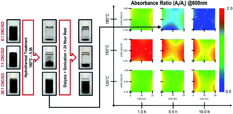 | ||
| Fig. 1 Evolution of CNC + GO dispersions upon hydrothermal treatment as evidenced by visual inspection and UV-VIS spectroscopy. | ||
The structural evolution of graphene oxide and nanocrystalline cellulose, upon the hydrothermal treatment, is evaluated individually, noting no evident interaction in UV-Vis absorbance results at 150 °C for 1.0 hours (refer to Fig. 1). Tracking the evolution of oxygen-containing functional groups on GO reveals that after hydrothermal treatment at 150 °C for 1 hour (refer to Fig. 2), the critical difference is that the peak at 1400 cm−1 disappears, indicating the removal of OH groups. In subcritical water, acid-catalyzed dehydration is the primary reaction experienced by graphene oxide at low concentrations.16 Rising temperature will favor a reverse mechanism: acid-catalyzed hydration and an increase in water ionic product (KW, proton and hydroxide ion concentration). Nanocrystalline cellulose experiences partial desulfation and preservation of the cellulose I crystal structure after hydrothermal treatment (refer to Fig. 2). Desulfation of nanocrystalline cellulose, tracked by a decrease of 810 cm−1 peak intensity in Fig. 2, is believed to occur by an acid-catalyzed ester hydrolysis mechanism.17 Excessive desulfation may lead to agglomeration and precipitation of nanocrystalline cellulose along with reduced graphene. Therefore, cellulose's partial desulfation is critical to simultaneously achieving stable dispersions and restoring inter-fiber hydrogen bonding to promote graphene sheets' covering. This physical blocking mechanism of the individual sheets prevents the restacking of the same (refer to Fig. 3a and b). The above further suggests that at 150 °C and 1.0 hour, a reduction and desulfation trade-off is met during the simultaneous hydrothermal processing of both species (refer to Fig. 1).
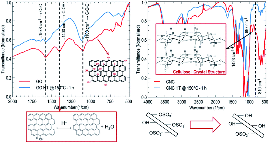 | ||
| Fig. 2 IR spectra of GO and CNC before and after hydrothermal treatment. | ||
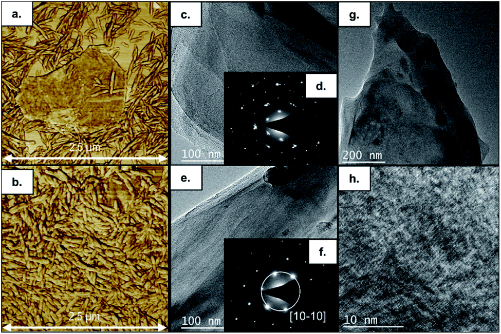 | ||
| Fig. 3 Evolution of CNC + GO dispersions before (a) and after (b) hydrothermal treatments as observed by AFM. TEM observation of 0CNC–5G (c) and 5CNC–5G (e, g, and h) samples with their corresponding electron diffraction patterns (d and f). | ||
In situ polymerization of 1,4-benzoquinone is performed in cellulose-nanocrystals/graphene, cellulose-nanocrystals, and graphene aqueous dispersions (refer to Fig. 4). After polymerization, a dark-brown precipitate is appreciated at the bottom of the flask. Upon precipitate filtering to remove low-weight oligomers, a sharp filtrate UV-Vis absorbance peak at 288 nm progressively reduces its intensity (refer to Fig. 4). The onset of the spectrum gradually redshifts, suggesting conjugation length increase due to polymerization (refer to Fig. 4). The absorbance peak corresponds to the π–π transition of electrons in hydroquinone. The precipitate molecular infrared ‘fingerprint’ reveals a co-polymer structure containing benzoquinone and hydroquinone rings (refer to Fig. 4 for 5CNC–0G case). Besides polymer chains' characteristic signature, there is no evidence of new covalent bonds suggesting that polymer-additive interaction only involves van der Waals interactions. Avoiding covalent bonding is particularly desirable to maintain the graphene conjugated structure. The polymerization mechanism for 1,4-benzoquinone (refer to Fig. 4) involves a cationic chain growth process.18,19 Each sample is labeled XCNC–YG, where X and Y represent the CNC/pBQ and G/pBQ mass fraction percentages.
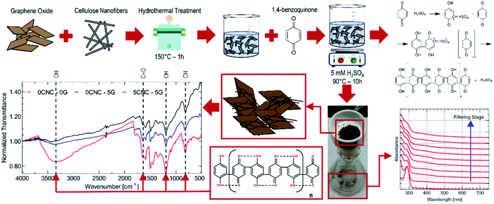 | ||
| Fig. 4 Polyquinone composite synthesis protocol and molecular fingerprint. | ||
The surface morphology for sample 0CNC–5G seems to be formed by a ladder-like arrangement of stacked sheets, while sample 5CNC–5G reveals a flatter pattern (refer to Fig. 3c and d). Under normal incidence, the electron diffraction pattern for sample 5CNC–5G (refer to Fig. 3f) is correlated with graphene.20 The intensity of peak [10–10] is stronger than that of [11–20], neglecting ABA… or ABC… graphene stacking and thus suggesting the presence of a monolayer. Although an AA⋯A stacking pattern would be possible; reports of such arrangement are scarce. In the absence of cellulose, a few-layer turbostratic stacking electron diffraction pattern is observed (refer to Fig. 3d). This particular agglomeration results from graphene stacking upon reduction from graphite oxide as remaining functional groups prohibit an ABA… pattern typical of mechanically exfoliated graphene.21 It should also be noted that the TEM image indicates that the sheet's surface is not uniform, and an amorphous layer is present on the top. Thus, cellulose nanocrystals stabilizing effect on graphene dispersions is retained during polymerization, enabling the polymer to coat monolayer graphene sheets. It should also be noted that the TEM images indicate that the sheet's surface is not uniform, and an amorphous layer is present on the top indicating coverage by the polymer (refer to Fig. 3g and h). For a capacitive behaviour, a relatively short diffusion path is beneficial for fast faradaic reactions to occur at electrode/electrolyte interface. Thus, porous nanostructures increase the contact area between electrolyte and active materials improving power performance and active material usage. This phenomenon has been documented for polymeric electroactive materials by adjusting surface morphology through the polymerization method, dopant content, oxidation level, type of surfactant, surfactant content, and coating over different nanostructures.22 A stable coating over the nanostructures can further provide a higher cycling life due to a more efficient strain accommodation upon charge/discharge.
Quinones reduce in aqueous acidic conditions in a single step involving two electrons and two protons, which is seen as a single reversible wave in the associated voltammogram23 (refer to Fig. 5). The addition of cellulose slows down redox transitions, with less-resolved peaks detected as nanofiber concentration increases. Graphene reduces peak separation substantially, implying an improvement in reaction kinetics. However, the peak separation for the 5CNC–5G case is even smaller, implying that redox kinetics greatly benefit from more effective graphene usage through the presence of cellulose nanocrystals as mono-to few-layer sheet stabilizers. Due to the significant peak separations in the corresponding voltammogram, the composite polymer displays an electrochemical fingerprint characteristic of battery-type materials with no apparent phase transition during the charging/discharging.
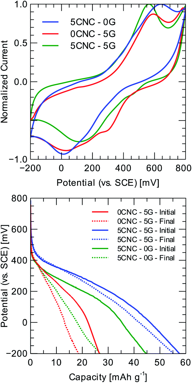 | ||
| Fig. 5 Cyclic voltammetry (5 mV s−1) and galvanostatic discharge (0.1 A g−1) profiles for selected polyquinone composite samples. Set-up: 1 M HCl as the electrolyte, saturated calomel electrode (SCE) as the reference electrode, and porous carbon rod as the counter electrode. | ||
A two-electrode cell is assembled to assess the material's cyclability and tested at 1 A g−1 for 50 charge/discharge cycles to perform a comparison between electrodes with different G and CNC loading. As the electrolyte, 1 M HCl is utilized, and the counter electrode is a porous carbon rod. The evolution of the composites discharge profiles (refer to Fig. 5 and Table 1) indicates that the single inclusion of graphene provides minimal improvement regarding specific capacity: 28.3 ± 1.2 mA h g−1, and capacity retention 67.8 ± 5.2% at 0.1 A g−1. It should be noted that the introduction of cellulose nanocrystals provides a substantial improvement in electrochemical performance: for the 5CNC–5G sample, the specific capacity reaches 57.3 ± 1.5 mA h g−1, and the capacitance retention is 97.1 ± 3.6% at 0.1 A g−1 after 50 cycles of charge/discharge. A 5CNC–0G control sample displayed a higher specific capacity than 0CNC–5G: 49.0 ± 2.4 mA h g−1. The above suggests that CNC is more effective at the same mass loading (5 wt%). CNC fiber-like morphology might favor ion diffusion on the one hand, and on the other, G alone tends to restack, reducing its specific surface area.
| Sample | Capacity (mA h g−1) | Capacity retention (%) | Coulombic efficiency (%) |
|---|---|---|---|
| 0CNC–5G | 28.3 ± 1.2 | 67.8 ± 5.2 | 94.6 ± 4.0 |
| 5CNC–0G | 49.0 ± 2.4 | 59.3 ± 5.6 | 94.5 ± 4.5 |
| 5CNC–5G | 57.3 ± 1.5 | 97.1 ± 3.6 | 98.9 ± 2.1 |
Electrochemical impedance spectroscopy is especially practical for tracking the evolution of composite properties upon cycling (refer to Fig. 6a–c). An equivalent circuit model is assumed to make a quantitative comparison. The model used to fit the impedance data could be viewed as a modified version of the Randles circuit or a partially blocked electrode model (refer to Fig. 7e). The double-layer capacitive (CDL) current is separated from the faradaic current, implying that different ions are involved in each process. This double-layer capacitance represents “uncoated” carbon material in contact with the current collector through possible percolation paths. The Warburg element (W) is incorporated to model the diffusion of electroactive species. Finite diffusion is expected considering that it is mainly commanded by the redox transitions of the electrochemically active polymer film immobilized on the current collector and that no other active species are present in the electrolyte (no leakage current is assumed). Therefore, faradaic reactions result from inter-chain electron hopping or electric conduction (along carbon backbones) upon polymer oxidation/reduction, accompanied by diffusion and migration ions within the electrode.24 The RA element accounts for the film's adsorption of charged species (ions or solvent molecules). These species are not expected to exchange electrons; however, they change the surface charge density of the electrochemically active regions of the electrode. The CPEA element in the parallel path of RA is thus incorporated to represent the capacitive effect of adsorbed species not involved in the faradaic reaction. The adsorption resistance is in series with the charge transfer resistance (RCT), accounting for the rate of the polymer's kinetically controlled redox reactions. RC represents the resistance of electron-conducting paths within carbon polymer-coated regions of the composite, that is, in principle, non-dependent of redox state. Finally, the ESR element represents the equivalent series resistance (ESR), collecting the electrolyte resistance with the current collector's internal resistance.
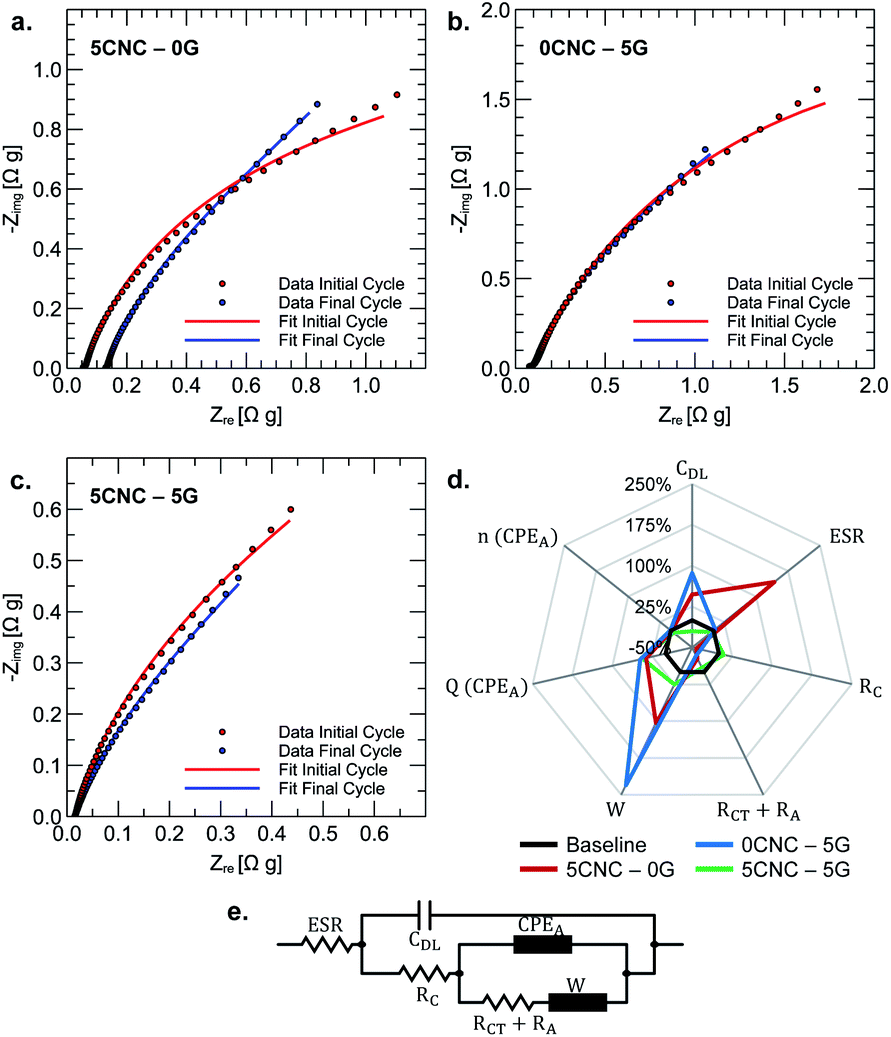 | ||
| Fig. 6 Nyquist plots at 600 mV vs. SCE for 5CNC–0G (a), 0CNC–5G (b), and 5CNC–5G (c) samples before and after cycling. Percentual change in the equivalent model parameters upon cycling (d). The equivalent circuit model to fit the impedance data (e). | ||
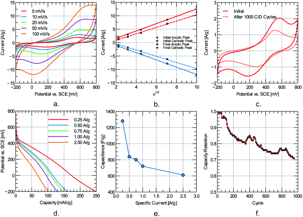 | ||
| Fig. 7 Electrochemical assessment of 5CNC–5G sample: (a) cyclic voltammetry at different scan rates, (b) peak current evolution with the square root of the scan rate, (c) voltammogram evolution at 5 mV s−1 after charging/discharging at 1000 cycles, (d) constant current discharge plots at different specific currents, (e) capacitance evolution with specific current and (f) capacity retention evolution versus charge/discharge cycle. | ||
The percentual change in the equivalent model parameters upon cycling is presented in the spider chart shown in Fig. 6d. The more pronounced changes associated with the polymer sample containing cellulose (5CNC–0G) are an increased ESR (142.8%) and Warburg coefficient (103.4%). The former is attributed to the loss of contact between the composite and current collector at some locations. The latter is due to increased resistance of the diffusion process due to the concomitant area reduction. This explanation suggests that the interchain interaction between cellulose fibers creates a film that cannot withstand the mechanical cycling due to the shrinking and swelling of the electrode upon charge and discharge.
In contrast, there is no significant change in ESR for the sample containing graphene (0CNC–5G) but a more notorious change in the Warburg coefficient (230.6%). The transition into a more compact and less porous film upon cycling is a plausible explanation for diffusion hindering. This compact layer could result from gradual graphene restacking promoted by the film's shrinking and swelling upon charge–discharge cycling. For both cases, the increased capacitances associated with adsorbed species and double layer indicate a wettability improvement. The improvement implies increasing the specific surface area composite-electrolyte, further reducing RC and RA + RCT resistances. The sample containing cellulose and graphene shows a stable ESR, RC, and RA + RCT resistance. There is an increase in capacitance associated with adsorbed species (CPAA) but a decrease in double-layer capacitance (CDL). Partial clogging of uncoated porous carbon could explain the decreased double-layer capacitance. Tomai et al. evidenced a degradation mechanism for quinone electrodes characterized by expansion of an inactive domain of hydroquinones.25 It could then be theorized that this inactive region expands toward un-coated carbon, diminishing the available surface for double layer formation. Overall, a synergic effect between cellulose nanocrystals and graphene gives rise to a mechanically stable composite upon continuous charge and discharge.
5CNC–5G sample is further electrochemically characterized to assess its charge storage performance in more detail. For subsequent studies, to increase the utilization rate of the electrode's Specific Surface Area (SSA), isopropyl alcohol was added to 1 M HCl to create a 10% v/v solution for the electrolyte. Isopropyl alcohol is chosen for its low surface tension and compatibility with carbon-based surfaces.26 The electrochemical evaluation is performed in a three-electrode set-up consisting of 5CNC–5G composite, porous carbon rod, and Saturated Calomel Electrode (SCE) as working, counter, and reference electrode, respectively. The electrode degradation is evaluated by galvanostatic charge and discharge up to 1000 cycles at 1 A g−1.
Cyclic voltammetry results reveal well-resolved redox peaks for the quinone two-electrons and two-protons transition up to a scan rate of 100 mV s−1 (refer to Fig. 7a). Redox kinetics of the electrode material is assessed by tracking the anodic and cathodic peak current dependency with scan rate. The ip–υ1/2 plot (refer to Fig. 7b) shows a linear relationship for the anodic and cathodic peaks. This behavior suggests a diffusion-limited charge transfer mechanism that could be approximately modeled with the Randles–Sevcik equation (at 25 °C):
| Ip = (2.69 × 10⁵)n3/2AD1/2Cv1/2 |
Ip is the peak current, n is the number of electrons involved in the charge transfer process, A (cm2) is the surface area, C (mol cm−3) is the concentration of the diffusing species, D (cm2 s−2) is the diffusion coefficient of the diffusing species, and v (V s−1) is the scan rate. Considering that ion diffusion within the polymer film is the limiting process, the diffusion coefficient of the system could be roughly estimated from the Randles–Sevcik relation. The diffusion coefficient for the oxidation step evolves from 1.70 × 10⁻⁸ cm s−2 to 2.07 × 10⁻⁸ cm s−2 after cycling. The order of magnitude is comparable to other high-rate organic-modified carbon electrodes for capacitive energy storage.27 A slight increase is noted upon cycling, suggesting that the electrode's degradation does not comprise a decrease of mass transport as the primary mechanism. The evolution of the diffusion coefficient correlates to the decrease in peak separation and peak anodic/cathodic current after cycling (refer to Fig. 7c). Upon continuous charge/discharge, diffusion paths within the electrode are consolidated, enhancing the rate of the mass transport phenomena. However, the reduction in peak current indicated that simultaneously, some degradation in the composite's electroactive characteristic (charge transfer kinetics) is expected.
The constant current discharge curves for the 5CNC–5G sample is shown in Fig. 7d at different specific currents. The curves resemble a linear discharge behavior for the whole range after neglecting the initial portion corresponding to the ohmic drop. The electrode specific capacitance is approximated from the slope of the linear region of the discharge plot. The largest measured capacitance is 1282.2 F g−1 at 0.25 A g−1 within a potential window of 700 mV. The electrode capacitance could be divided into a rate-independent and diffusion-limited components according to the relation:28
| C = C0 + at1/2 |
C0 represents the rate-independent component, a is a proportionality constant, and t represents the time to discharge. For the data shown in Fig. 7e, the rate-independent component is 416.6 F g−1, which is often attributed to the effective double-layer contribution and represents the minimum attainable capacitance of the electrode for the electrochemical cell set-up.
Considering that capacitance might not be a reliable performance metric for the diffusion-limited storage process evidenced by CV,29 the capacity of the electrode is also reported (refer to Fig. 7e). The maximum measured capacity is 249.9 mA h g−1 at 0.25 A g−1 and drops to 101.1 mA h g−1 at 2.50 A g−1.
Over 70% of the capacity is retained after 1000 charge/discharge cycles at 1 A g−1. To better understand capacity fade, the EIS fingerprint is compared before and after cycling using the equivalent circuit described in Fig. 6e. No apparent semi-circle is observed at high frequencies (refer to Fig. 8a and b), resembling a capacitive material where no charge transfer is expected cause the energy is stored physically. However, the active material performs redox reactions, which could give rise to interfacial effects. The lack of such effect in the Nyquist plot at different potentials suggests a low interfacial impedance at the current-collector/electrode-material interface. At low frequencies, the Nyquist curve resembles that of a capacitive material. However, no constant phase is identified on the corresponding Bode plot for a truly capacitive constant-phase behavior. Semi-infinite diffusion is not always met because diffusing species are either trapped in the electrolyte-filled nanopores or the solid phase of the nanoparticles.30 The lowest impedances are measured at 400 mV near the standard redox potential for quinone in acidic solutions. Fitting the spectra to the equivalent circuit shown in Fig. 6e reveals that the most profound changes involve the increase in RA + RCT resistance (1545%) and decrease in Warburg coefficient (−100%) (refer to Fig. 8c). Therefore, even at 1000 cycles, the degradation seems to involve inactive domain expansion.
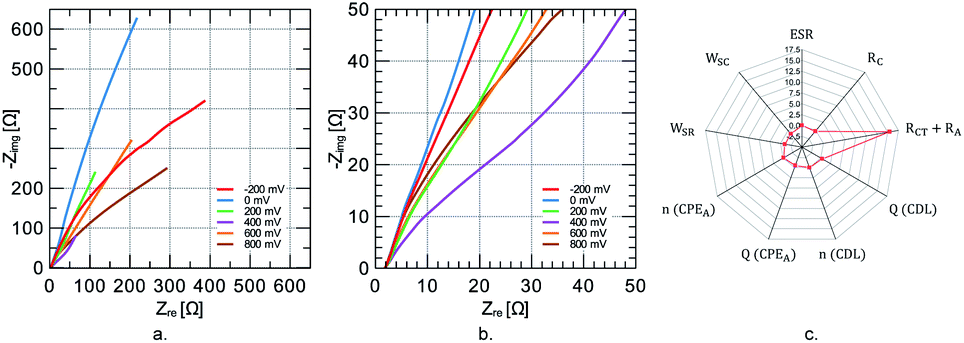 | ||
| Fig. 8 Nyquist plots at different potentials for 5CNC–5G sample (a) and (b). Percentual change in the equivalent model parameters upon cycling (c). | ||
Overall, the high capacity retention for the 5CNC–5G case could be explained by the more efficient exploitation of graphene loading than 0CNC–5G. Quinone molecules in nanopores of activated carbon display >90% capacity retention after 1000 charge/discharge cycles.31 The effect could be explained by considering the increase in the π–π interaction between the graphene surface and aromatic quinone rings. Hence, cellulose nanocrystals, helping reduce graphene restacking chances during polymerization, allow more contact between sheets and polymer.
Conclusions
1,4-Benzoquinone is cationically polymerized in a dilute (25 mM) H2SO4 aqueous dispersion containing cellulose nanocrystals and mono- to few-layer reduced graphene oxide. Hydrothermal treatment of graphene oxide dispersions in the presence of cellulose nanocrystals improves the stability of reduced graphene oxide in an aqueous medium. The restacking-prevention action of cellulose nanocrystals considerably improved graphene effectiveness as a nano-additive, improving the electrochemical performance of polyquinone-based composite electrodes. The interfacial area between polymer and nano-filler is particularly increased because 1,4-benzoquinone molecules coat mono to few-layer graphene sheets during polymerization. The specific capacitance and capacity of a sample consisting of 5 wt% CNC and 5 wt% G reached 720.5 F g−1 and 129.6 mA h g−1 at 1 A g−1. Further, at 1 A g−1, over 70% of the initial capacity was preserved after 1000 cycles. The degradation mechanism is theorized to be the expansion of polyquinone inactive domains. No evidence of kinetic degradation is measured over cycling thanks to cellulose nanocrystals' graphene restacking prevention effect.Author contributions
Conceptualization, DI; investigation, DI and HG; resources, HG; writing – original draft preparation, DI and HG; writing – review & editing, DI, MR and HG; supervision, MR and HG; project administration, HG.Conflicts of interest
There are no conflicts to declare.Acknowledgements
The authors would like to acknowledge Minciencias for the financial support given within the framework of the PhD National Scholarship Colciencias No. 617-2014 (UN-OJ-2014-26159).References
- J. F. Peters, M. Baumann, B. Zimmermann, J. Braun and M. Weil, Renewable Sustainable Energy Rev., 2017, 67, 491–506 CrossRef CAS.
- C. Liedel, ChemSusChem, 2020, 13, 2110–2141 CrossRef CAS PubMed.
- A. Mauger, C. Julien, A. Paolella, M. Armand and K. Zaghib, Materials, 2019, 12, 1770 CrossRef CAS PubMed.
- H. Oubaha, J. Gohy and S. Melinte, Chempluschem, 2019, 84, 1179–1214 CrossRef CAS PubMed.
- J. Heiska, M. Nisula and M. Karppinen, J. Mater. Chem. A, 2019, 7, 18735–18758 RSC.
- K. Amin, L. Mao and Z. Wei, Macromol. Rapid Commun., 2019, 40, 1800565 CrossRef.
- Z. Zhu, G. Xiao, J. Chen and S. Fu, Cellulose, 2020, 27, 8513–8526 CrossRef CAS.
- M. Arbabzadeh, J. X. Johnson, G. A. Keoleian, P. G. Rasmussen and L. T. Thompson, Environ. Sci. Technol., 2016, 50, 1046–1055 CrossRef CAS.
- C. Han, H. Li, R. Shi, T. Zhang, J. Tong, J. Li and B. Li, J. Mater. Chem. A, 2019, 7, 23378–23415 RSC.
- J. Cao, P. He, M. A. Mohammed, X. Zhao, R. J. Young, B. Derby, I. A. Kinloch and R. A. W. Dryfe, J. Am. Chem. Soc., 2017, 139, 17446–17456 CrossRef CAS PubMed.
- D. Illera, C. Wickramaratne, D. Guillen, C. Jotshi, H. Gomez and D. Y. Goswami, in Materials: Genetics to Structures, American Society of Mechanical Engineers, 2018, vol. 12 Search PubMed.
- M. Cao, N. Wang, L. Wang, Y. Zhang, Y. Chen, Z. Xie, Z. Li, E. Pambou, R. Li, C. Chen, F. Pan, H. Xu, J. Penny, J. R. P. Webster and J. R. Lu, J. Mater. Chem. B, 2016, 4, 152–161 RSC.
- N. Lin and A. Dufresne, Nanoscale, 2014, 6, 5384–5393 RSC.
- P. M. Carrasco, S. Montes, I. García, M. Borghei, H. Jiang, I. Odriozola, G. Cabañero and V. Ruiz, Carbon, 2014, 70, 157–163 CrossRef CAS.
- A. M. Abdelkader, A. J. Cooper, R. A. W. Dryfe and I. A. Kinloch, Nanoscale, 2015, 7, 6944–6956 RSC.
- Y. Zhou, Q. Bao, L. A. L. Tang, Y. Zhong and K. P. Loh, Chem. Mater., 2009, 21, 2950–2956 CrossRef CAS.
- S. Beck and J. Bouchard, Nord. Pulp Pap. Res. J., 2014, 29, 006–014 CrossRef CAS.
- M. W. Sabaa, T. M. Madkour and A. A. Yassin, Polym. Degrad. Stab., 1988, 22, 195–203 CrossRef CAS.
- T. M. Madkour, Polym. J., 1997, 29, 670–677 CrossRef CAS.
- J. C. Meyer, in Graphene, Elsevier, 2014, pp. 101–123 Search PubMed.
- C. Gómez-Navarro, J. C. Meyer, R. S. Sundaram, A. Chuvilin, S. Kurasch, M. Burghard, K. Kern and U. Kaiser, Nano Lett., 2010, 10, 1144–1148 CrossRef.
- Y. Xue, S. Chen, J. Yu, B. R. Bunes, Z. Xue, J. Xu, B. Lu and L. Zang, J. Mater. Chem. C, 2020, 8, 10136–10159 RSC.
- P. S. Guin, S. Das and P. C. Mandal, Int. J. Electrochem., 2011, 2011, 1–22 CrossRef.
- G. Inzelt, Conducting Polymers, Springer, Berlin, Heidelberg, 2012, pp. 191–244 Search PubMed.
- T. Tomai, H. Hyodo, D. Komatsu and I. Honma, J. Phys. Chem. C, 2018, 122, 2461–2466 CrossRef CAS.
- T. Liu, K. Wang, Y. Chen, S. Zhao and Y. Han, Green Energy Environ., 2019, 4, 171–179 CrossRef.
- Z. Song, L. Miao, L. Li, D. Zhu, Y. Lv, W. Xiong, H. Duan, Z. Wang, L. Gan and M. Liu, J. Mater. Chem. A, 2020, 8, 3717–3725 RSC.
- T. Lin, I.-W. Chen, F. Liu, C. Yang, H. Bi, F. Xu and F. Huang, Science, 2015, 350, 1508–1513 CrossRef CAS PubMed.
- T. S. Mathis, N. Kurra, X. Wang, D. Pinto, P. Simon and Y. Gogotsi, Adv. Energy Mater., 2019, 9, 1902007 CrossRef CAS.
- D. Qu, G. Wang, J. Kafle, J. Harris, L. Crain, Z. Jin and D. Zheng, Small Methods, 2018, 2, 1700342 CrossRef.
- T. Tomai, S. Mitani, D. Komatsu, Y. Kawaguchi and I. Honma, Sci. Rep., 2015, 4, 3591 CrossRef PubMed.
Footnote |
| † Current affiliation: Energy, Materials and Environment (GEMA) Research Group, Universidad de La Sabana, Campus Universitario del Puente del Común, Km 7 Autopista Norte de Bogotá, Chía, Cundinamarca, Colombia, Email: E-mail: danny.illera@unisabana.edu.co. |
| This journal is © The Royal Society of Chemistry 2022 |