DOI:
10.1039/D2RA00660J
(Paper)
RSC Adv., 2022,
12, 14535-14543
Room-temperature coalescence of Pd nanoparticles with sacrificial templates and sintering agents, and their catalytic activities in the Suzuki coupling reaction†
Received
31st January 2022
, Accepted 30th April 2022
First published on 13th May 2022
Abstract
Porous metal structures are very useful for heterogeneous catalysts in organic syntheses. This study reports a novel method to fabricate porous Pd structures by room-temperature (RT) coalescence of Pd nanoparticles (Pd NPs). First, oleylamine-capped Pd NPs were synthesized, and then Pd NP pastes were fabricated by mixing with tri-n-octylphosphine oxide as a sacrificial template. Finally, the Pd NP paste was dipped into methanol containing a sintering agent. When KOH was used as the sintering agent, porous Pd structures could be successfully obtained at RT. The catalytic activities of porous Pd structures were investigated in the Suzuki coupling reaction and they increased with the increase of the KOH concentration in the sintering process. These results indicate that pre-activation of porous Pd structures by KOH increased the catalytic activities.
Introduction
Pd is one of the most important and widely used metals in organic syntheses,1 purification of automotive exhaust gases2 and fuel cell technology.3 For example, Pd salts and Pd complexes, such as Pd(II) acetate and tetrakis(triphenylphosphine)palladium(0), are used as homogeneous catalysts.4,5 Homogeneous catalysts have potential problems such as difficult separation and recovery of catalysts from the reaction medium. In recent years, Pd nanoparticles (Pd NPs) have also been used as such catalysts due to their large surface area and excellent solvent dispersibility.1,6–12 However, Pd NPs tend to aggregate upon heating, which leads to serious decline in their catalytic abilities. To prevent Pd NPs from aggregation in the reaction, Pd NPs are normally covered with organic ligands. The ligands limit the reaction solvent where Pd NPs can disperse. The Pd NP-catalyzed reaction takes place less efficiently in unfavorable solvents due to the aggregation of NPs and the inhibition by ligands. The functional groups of ligands interact with the Pd NP surface and can potentially alter the bonding modes of the adsorbents, thereby affecting the catalytic activity.13
These days, porous metal structures (PMSs) have been reported as catalytic metals such as Ag,14,15 Ni,16,17 Au,18,19 Pt,20,21 Pd (ref. 22 and 23) and their alloy metals (e.g. Cu–Ag,24 Pd–Au (ref. 25) and Pd–Ni (ref. 26)). In contrast to traditional porous materials such as silica and carbon, they possess intrinsic catalytic properties depending on the type of metal. Especially, nanoporous/mesoporous metals have been used as heterogeneous catalysts due to their extremely-large surface area and easy separation. Many types of PMSs have been fabricated by electrochemical methods.27 This type of method typically involves four main steps: (1) formation of a sacrificial template on the substrate and electrode; (2) filling of pores with target metal precursors; (3) reduction of the precursors by reducing agent and electrochemical reduction (4) selective removal of the template.27 However, only conductive electrodes (e.g. carbon) can be used as a substrate in this method. Also, PMSs are fabricated by electrochemical dealloying of the base metal in alloy.27 For example, Tanaka et al. has fabricated PMS of Pd67Ni23P10 from a glassy metallic alloy of Pd30Ni50P20.28 Although the selective dealloying requires a large amount of energy, it is difficult to obtain pure PMSs by this method.
The room-temperature (RT) chemical sintering method is conducted by dipping into a solvent containing a sintering agent at RT. In this method, only sintering agents are added to desorb organic ligands easily from metal NPs. This brings about the coalescence of metal NPs at RT. For example, Cl− (by dipping into a solvent containing NaCl or exposing to a vapor such as HCl)29–32 and OH− (by dipping into a solvent containing e.g., NaOH)33 have been used as sintering agents for the RT chemical sintering of Ag NPs. In our previous study, the RT chemical sintering of tri-n-octylphosphine oxide (TOPO)-capped Ag NPs and Cu@Ag NPs was conducted by dipping into methanol containing Cl−, such as hexadecyltrimethylammonium chloride (CTAC) and HCl.34–36 As the obtained metal thin films had many voids generated by the removal of TOPO in the sintering process, they are thought to be a type of PMS.
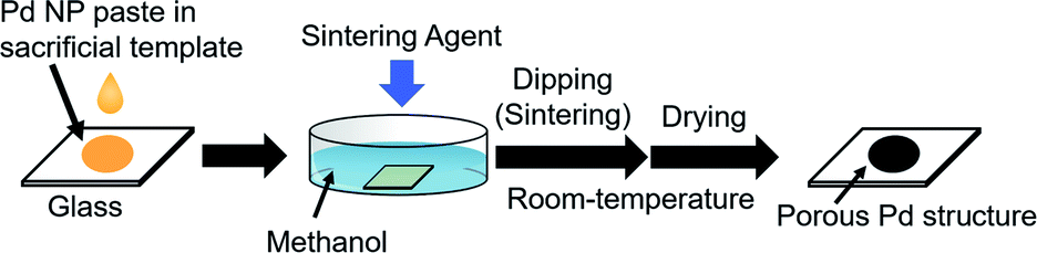
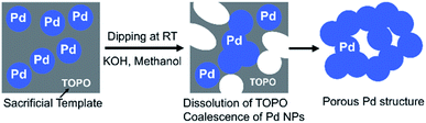
In this study, we created a new strategy for the fabrication of porous Pd structure by the RT chemical sintering of Pd NPs with sacrificial templates and sintering agents. The outline of the strategy is shown in Fig. 1. First, oleylamine-capped Pd NPs were mixed with TOPO as a sacrificial template to prepare the Pd NP paste. Then, porous Pd structures were fabricated at RT from Pd NPs by dipping into methanol containing a sintering agent. Since TOPO easily dissolves in methanol, the coalescence of Pd NPs proceeds even at RT with the aid of a sintering agent. Here, various sintering agents such as KOH, CTAC and HCl were examined. As porous Pd structures are expected to be heterogeneous catalysts, the Suzuki coupling reaction, which is a well-known Pd-catalyzed reaction,37–40 was performed for the evaluation of the catalytic abilities.
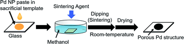 |
| | Fig. 1 Preparation of porous Pd structures on the glass substrate by RT chemical sintering of Pd NPs with a sacrificial template in methanol containing a sintering agent. | |
Experimental
Materials
All the chemicals and solvents were obtained commercially and used without further purification. Pd(II) acetylacetonate and borane–triethylamine complex were purchased from Sigma-Aldrich. n-Octadecane and TOPO were purchased from Aldrich. 1-Dodecanol was purchased from Nakarai Tesque, Inc. Potassium hydroxide (KOH), potassium carbonate (K2CO3), CTAC, oleylamine, iodobenzene and palladium-activated carbon (Pd 5 wt%, Pd/C) were purchased from Wako Pure Chemical Industries, Ltd. Hydrogen chloride methanol solution (6.6 w/w%), 4-iodophenol, phenylboronic acid and 4-methylphenylboronic acid were purchased from Tokyo Chemical Industries Co., Ltd.
Preparation of Pd NPs and Pd NP paste
Pd NPs were synthesized as below.41 Typically, Pd(II) acetylacetonate (70 mg) was dissolved in 15 mL of oleylamine by stirring at 60 °C for 10 min. After this solution was heated at 90 °C, 0.30 mL of borane–triethylamine complex as a reducing agent was added to this solution. Then, this solution was heated at 90 °C for 60 min. After the reaction, about 30 mL of methanol was added as an antisolvent to the dispersion of Pd NPs (about 20 mL). The dispersion was then centrifuged at 15![[thin space (1/6-em)]](https://www.rsc.org/images/entities/char_2009.gif) 000 rpm for 10 min. After the removal of the supernatant, about 20 mL of methanol was added to the residue again. The centrifugation was then performed at 5000 rpm for 10 min. The same procedure was repeated twice. The obtained oleylamine-capped Pd NPs (20 mg) were dried in air.
000 rpm for 10 min. After the removal of the supernatant, about 20 mL of methanol was added to the residue again. The centrifugation was then performed at 5000 rpm for 10 min. The same procedure was repeated twice. The obtained oleylamine-capped Pd NPs (20 mg) were dried in air.
Pd NP pastes were fabricated as below.35,36 First, oleylamine-capped Pd NPs (10 mg) were dispersed in 18 mL of n-heptane at a concentration of 0.56 g L−1. Next, the n-heptane solution of the sacrificial template (5.0 g L−1, 2 mL) was added to the dispersion of Pd NPs. The sacrificial templates used here were TOPO, n-octadecane and 1-dodecanol. The concentrations after mixing were adjusted to 0.50 g L−1 of Pd NP. The mixture was stirred at 40 °C for an hour. Then, n-heptane was completely removed by a rotary evaporator to increase the NP concentration in the paste. The concentrated sacrificial template dispersion of Pd NPs was used without purification as the Pd NP paste (metal/sacrificial template = 8.6/500 w/w%) in the preparation of porous Pd structures (see the following paragraph). Although the paste contains oleylamine as an impurity, the amount (about 1.4 mg) is very small compared with that (100 mg) of the sacrificial template. Therefore, the effect of impurities would be negligible.
Preparation of porous Pd structures
Glass substrates were washed with acetone and deionized water before use. Several drops of the fabricated Pd NP paste were cast onto the glass substrate (24 mm × 24 mm). This substrate was dipped in 20 mL of methanol containing a sintering agent at RT (about 25 °C) for 30 min in air. The sintering agents used here were CTAC, HCl and KOH. Methanol was used as a solvent in all cases. After the RT chemical sintering, the obtained porous Pd structures were washed by centrifugation with pure methanol (5000 rpm, 5 min). After the removal of the supernatant, pure methanol was again added to the residue under an ultrasonication. The centrifugation was conducted at 4000 rpm for 10 min. The same procedure was repeated twice. Then, the obtained porous Pd structures were dried in air for 30 min at RT.
General procedure of Suzuki coupling reaction with Pd as a catalyst
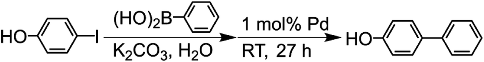
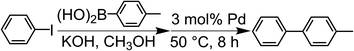
The Suzuki-coupling reaction in methanol was conducted based on the method reported by Tanaka et al. (Scheme 1).28 Typically, iodobenzene (1.0 mmol) and 4-methylphenylboronic acid (1.4 mmol) were added to the KOH methanol solution (5.0 mmol/4.0 mL) at RT. This solution was added into a centrifuge tube containing a 3 mol% Pd catalyst (porous Pd structure, Pd/C and Pd NPs) with respect to the substrate and the reaction mixture was stirred for 8 h at 50 °C. For tracing the reaction, 90 μL of the reaction solution was fractionated. The fractionated solution was filtrated by the membrane filter to remove Pd catalysts. The filtrated solution was added to the mixed solution of n-hexane and water. The organic compounds were extracted to the n-hexane phase. The reaction ratio of 4-methylbiphenyl was coursed by analyzing the extracted solution with gas chromatography-mass spectrometry (GC-MS). The reaction ratio was determined by the calibration curve described later.
 |
| | Scheme 1 Suzuki coupling reaction of iodobenzene with 4-methylphenylboronic acid catalyzed by Pd in methanol. | |
The Suzuki-coupling reaction in water was conducted based on the method reported by Sakurai et al. (Scheme 2).42 Typically, 4-iodophenol (3.0 mmol) and phenylboronic acid (5.0 mmol) were added to the K2CO3 aqueous solution (9.0 mmol/30 mL) at RT. This solution was added into a centrifuge tube containing a 1 mol% porous Pd structure with respect to the substrate, and the reaction mixture was stirred for 27 h at RT. For tracing the reaction, 90 μL of the reaction solution was fractionated. The fractionated solution was filtrated by the membrane filter for the removal of Pd catalysts. The filtrated solution was added to the mixed solution of n-hexane and 1.2 M HCl aqueous solution. The organic compounds were extracted from the aqueous phase to the n-hexane phase. The reaction ratio of 4-hydroxybiphenyl was determined by analyzing the extracted solution with GC-MS.
 |
| | Scheme 2 Suzuki coupling reaction of 4-iodophenol with phenylboronic acid catalyzed by Pd in water. | |
The leaching test of Pd in the Suzuki coupling reaction was performed by inductively coupled plasma atomic emission spectroscopy (ICP-AES). The sample solution was prepared by the following procedure. After the reaction was completed, the reaction solution (4.0 mL) was evaporated. The residue was dissolved in aqua regia (3.0 mL) and H2SO4 (1.0 mL), and then it was diluted with the 1% HNO3 and 2% HCl aqueous solution up to 9.0 mL. The precipitate was filtered off, and the filtrate was analyzed by ICP-AES. The conversion ratio (yield of biphenyl derivative) was determined by the calibration curve of the molar ratio (biphenyl/iodine phenyl) to the main peak area intensity ratio in mass chromatogram (MC). However, the peak area intensity contains about 10% of experimental errors in our study. MC was collected with the selected ion monitoring (SIM) method. The SIM method can detect selected ions at high sensitivity because only these ions were sent to a detector of MS. The calibration curves covered a wide range of molar ratios (biphenyl/iodine phenyl) (Fig. S1†).
Characterization
Transmission electron microscopy (TEM) images were taken at 100 kV with a JEM-2100 (JEOL, Japan) for the observation of synthesized Pd NPs and porous Pd structures. The diameter of NPs was evaluated by ImageJ software. The morphology of porous Pd structures was characterized by field emission scanning electron microscopy (FE-SEM, JSM-6700F and JSM-7800F, JEOL, Japan). Thermogravimetric analysis (TGA) was performed by a ThermoMass Photo (Rigaku, Japan). MC for the analysis of the conversion ratio (yield of biphenyl derivative) were obtained from GC-MS, PARVUM 2 (Shimadzu, Japan), equipped with DB-1 (Agilent J&W Scientific, USA) as a column. Total ion chromatograms (TICs) for the analysis of organic residue in Pd NPs were obtained from GC-MS, QP2010 Plus (Shimadzu, Japan). Here, Ultra ALLOY UA5-30M-0.25F (Frontier Laboratories Ltd., Japan) was used as a column. The Pd NPs for GC-MS were heated by a PY-3030D pyrolyzer (Frontier Laboratories Ltd, Japan) at 300 °C before injection. X-ray diffraction (XRD) patterns were recorded using a MiniFlexII (Rigaku, Japan, Cu Kα radiation) equipped with a Kα filter operating at 30 kV and 15 mA. The crystallite size was calculated by the Scherrer equation: D = 0.9λ/βcosθ, where D is the crystallite size, λ is the wavelength of X-ray, β is the full width at half maximum (FWHM) of the diffraction peak and θ is the diffraction angle.34–36 X-ray photoelectron spectroscopy (XPS) were performed by a KRATOS AXIS Ultra DLD X-ray photoelectron spectrometer (Shimadzu, Japan). The leached Pd was quantitated by ICP-AES (SPECTRO BLUE, Hitachi, Ltd., Japan). The N2-adsorption measurement was performed using an automatic N2-adsorption equipment, Belsorp-miniII (MicrotracMRB Corp., Japan). The sample was degassed and dried in a desiccator with silica gels at 293 K for 24 h prior to the N2-adsorption measurement at 77 K. The specific surface area was determined by BET analysis from the adsorption data in the range of relative pressure between 0.05 and 0.3.
Results and discussion
Preparation of Pd NP pastes and RT chemical sintering
The synthesis of oleylamine-capped Pd NPs was conducted based on the method reported by Mazumber et al.41 Regarding the obtained Pd NPs, TEM observation was performed (Fig. S2a†). From the analysis of TEM images, the average diameter of Pd NPs was determined to be 5.6 ± 0.6 nm (Fig. S2b†). This result clearly indicates that Pd NPs did not coalesce at all before the sintering process for the fabrication of porous Pd structures.
Pd NP pastes were prepared by mixing of oleylamine-capped Pd NP and a sacrificial template (TOPO, 1-dodecanol and n-octadecane). The melting points of all the sacrificial templates selected here are around 40 °C. The surface ligand of Pd NPs was characterized by pyrolysis GC-MS measurements after the RT chemical sintering with the 10 mM KOH methanol solution. Fig. S3† shows TICs of the sacrificial templates and Pd NPs before and after the RT chemical sintering. While the peak of oleylamine was detected in the case of Pd NPs before and after mixing the template, the peaks of the sacrificial template were scarcely detected in these cases. This result indicates that the ligand exchange from oleylamine to the sacrificial template hardly proceeded on the surface of Pd NPs and that the sacrificial templates were easily removed by washing with the 10 mM KOH methanol solution.
Effect of sacrificial templates on RT chemical sintering of Pd NPs
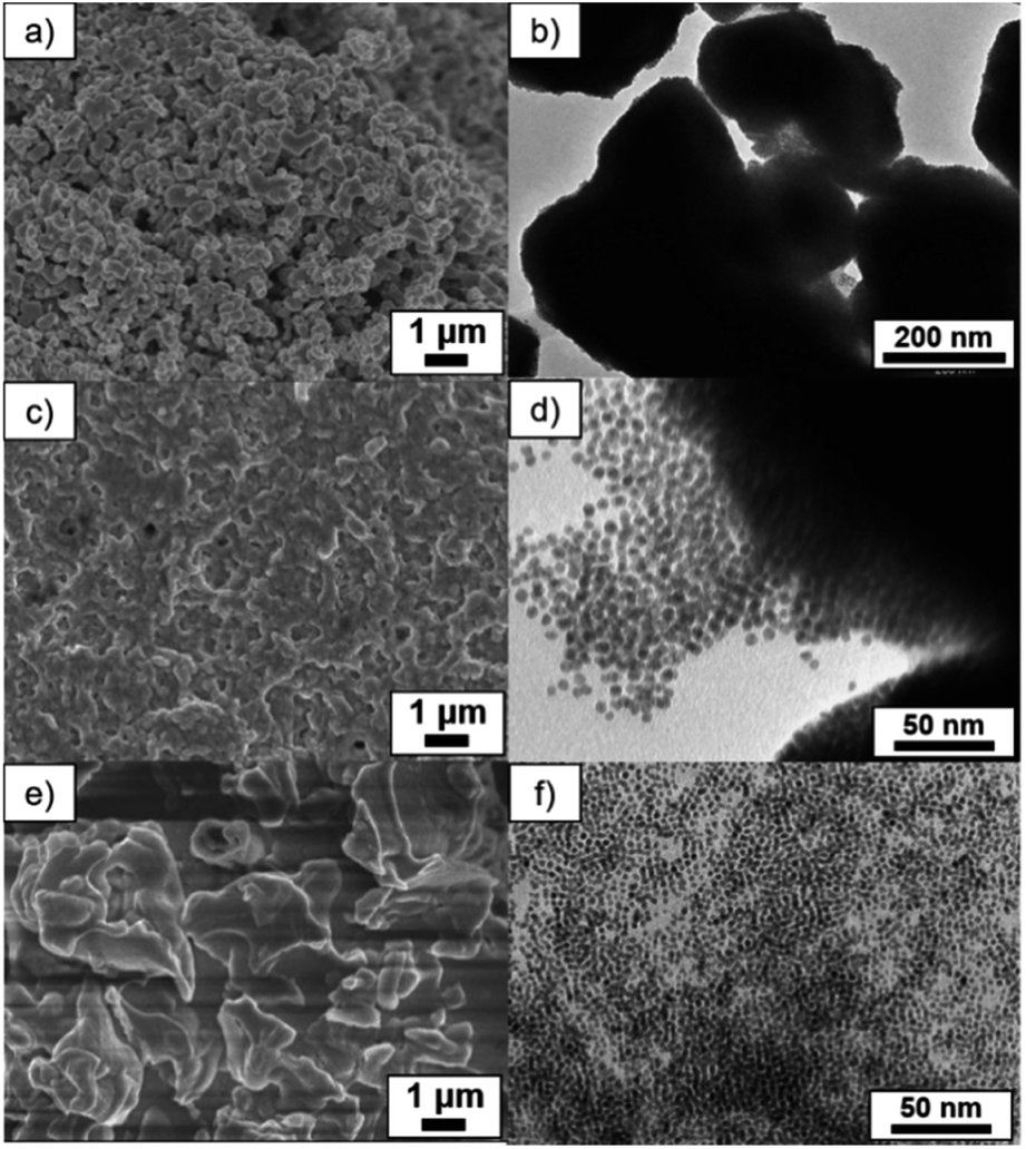
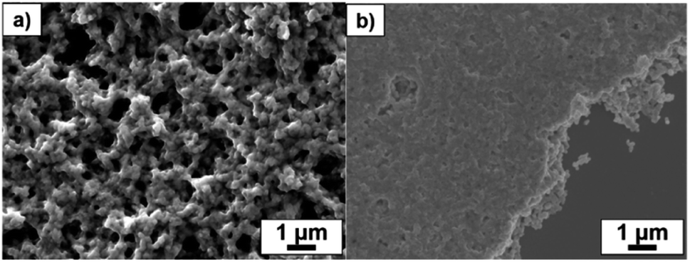
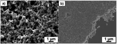
At first, KOH was used as the sintering agent. KOH is often used for the activation of Pd catalysts and it is easily soluble in methanol. The Pd NP paste containing a sacrificial template was cast on the glass substrate and it was sintered at RT by dipping into the 10 mM KOH methanol solution for 30 min. In order to obtain Pd porous structures by the RT chemical sintering, Pd NPs should be dispersed in the sacrificial template and then coalesce each other via removing the templates by the dissolution in methanol. In the case of the TOPO paste, organic residues were mostly removed and NPs were hardly observed after the RT chemical sintering, as shown in SEM and TEM images (Fig. 2a and b). On the other hand, NPs hardly coalesced in the case of the 1-dodecanol paste (Fig. 2c and d) because they aggregated in 1-dodecanol. In the case of the n-octadecane paste, organic residues covered NPs and inhibited their coalescence (Fig. 2e and f). Although Pd NPs dispersed in n-octadecane, n-octadecane was hardly removed by methanol due to its low solubility. These results demonstrate that in this RT chemical sintering, the miscibility of the sacrificial template with Pd NPs and methanol plays an important role and that TOPO is the best sacrificial template for the formation of porous Pd structures in methanol (Fig. 3).
 |
| | Fig. 2 SEM and TEM images of Pd structures prepared using (a), (b) TOPO, (c), (d) 1-dodecanol and (e), (f) n-octadecane by dipping into the 10 mM KOH methanol solution. | |
 |
| | Fig. 3 RT chemical sintering of the TOPO paste of Pd NPs by dipping into methanol containing a sintering agent. | |
Effect of sintering agents on RT chemical sintering of Pd NPs
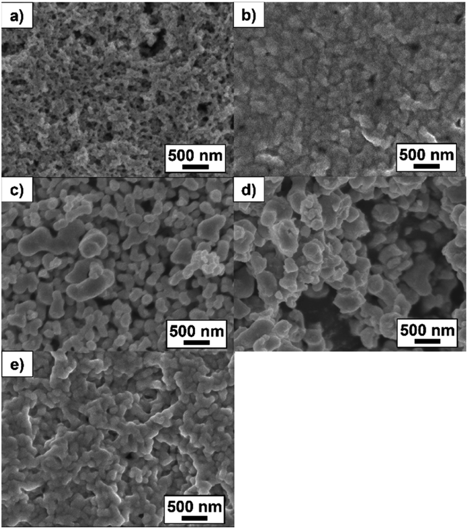
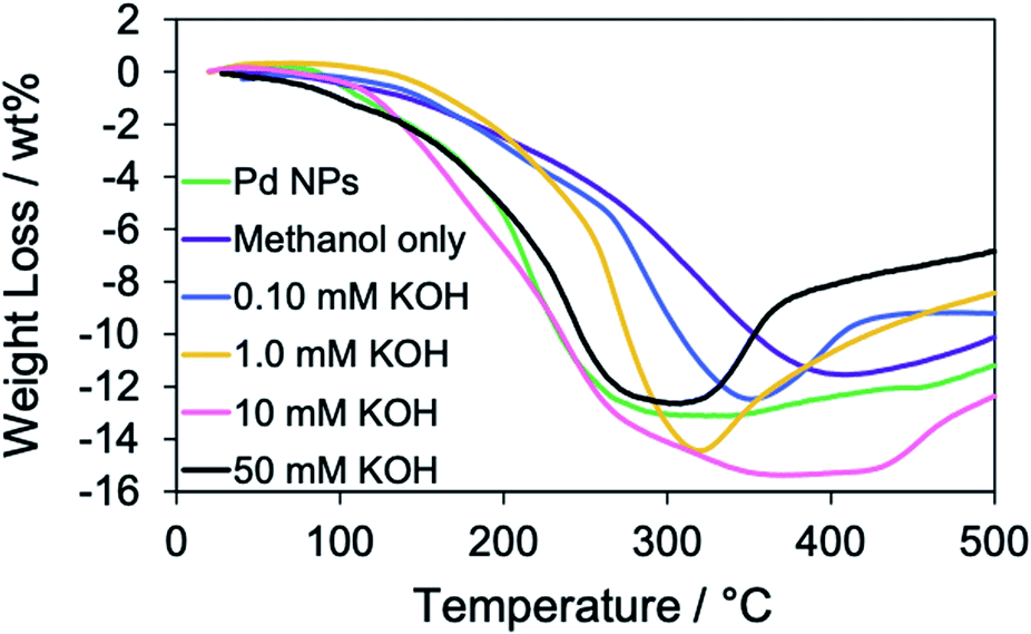
Next, the effect of the KOH concentration on the RT chemical sintering was investigated using the TOPO paste of Pd NPs. According to the SEM images (Fig. 4), the increase of the KOH concentration promoted the coalescence of Pd NPs. The amounts of organic compounds in the Pd structures were evaluated by TGA (Fig. 5). Heating was performed under a helium atmosphere at a rate of 10 °C min−1 in the temperature range from 30 to 500 °C. In the case of methanol only, the weight loss decreased compared with that of oleylamine-capped Pd NPs. This assumes the loss of ligands on the particle surface. The increase of the KOH concentration contributed to the increase of maximum weight losses at around 350 °C. This result indicates that the Pd methoxide and Pd–OH generated with the aid of KOH.1,43 In the case of 50 mM KOH, the weight loss decreased compared with that in the case of 10 mM KOH. Since the surface area of the Pd structure became smaller due to their coalescence, the amount of Pd methoxide and Pd–OH on the surface of Pd decreased. Namely, the optimized KOH concentration is required for the activation of porous Pd structures. The weight increase was observed at over 350 °C. This phenomenon may be originated from partial oxidation of Pd by residual oxygen.44
 |
| | Fig. 4 SEM images of Pd structures prepared from the TOPO paste of Pd NPs by dipping into methanol in the (a) absence and presence of (b) 0.10 mM, (c) 1.0 mM, (d) 10 mM and (e) 50 mM KOH. | |
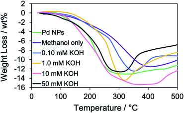 |
| | Fig. 5 TGA curves of oleylamine-capped Pd NPs (before the RT chemical sintering) and Pd structures prepared from the TOPO paste of Pd NPs by dipping into methanol in the absence and presence of 0.10 mM, 1.0 mM, 10 mM and 50 mM KOH in a helium atmosphere. | |
Other types of sintering agents, which are 1.0 mM CTAC and 29 mM HCl, were also examined using the TOPO paste of Pd NPs. The concentrations of sintering agents were set according to our previous study. In the case of HCl, organic residues were completely removed and the coalescence of Pd NPs was clearly observed (Fig. 6a). In the case of CTAC, however, organic residues were observed in almost all of the area (Fig. 6b). From these results, the coalescence of Pd NPs was affected by the acidity in the methanol solution. As TOPO is protonated under the acidic conditions, TOPO in the Pd NP paste is easily removed, which brings about the effective coalescence.36 Under the neutral conditions (CTAC), it may be difficult for TOPO to remove from the Pd NP paste because TOPO is not protonated. To confirm the point, the amounts of organic compounds in the Pd NPs after the RT chemical sintering were evaluated by TGA (Fig. S4†). When HCl was added into methanol, the weight loss decreased compared with those after the RT sintering with the 10 mM KOH and 1.0 mM CTAC methanol solutions.
 |
| | Fig. 6 SEM images of Pd structures prepared from the TOPO paste of Pd NPs by dipping into methanol in the presence of (a) 29 mM HCl and (b) 1.0 mM CTAC. | |
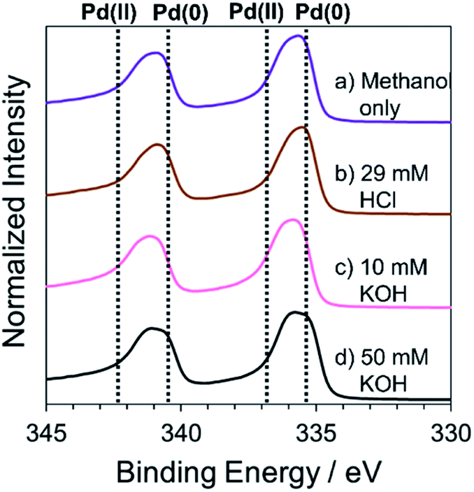
The elemental composition of Pd structures prepared by the RT chemical sintering was analyzed by XPS. The peaks at 335.3 eV and 340.5 eV were identified as Pd 3d5/2 and Pd 3d3/2 in Pd(0), respectively (Fig. 7). On the other hand, the peaks at 336.9 eV and 342.3 eV were identified as Pd 3d5/2 and Pd 3d3/2 in Pd(II), respectively.45,46 In all cases, the peaks of Pd(0) and Pd(II) were observed. The peak at around 336 eV was separated into two peaks using a software (Fig. S5†) and the molar ratio of Pd(0)/Pd(II) was determined based on the respective area of two peaks (Table 1). In the cases of KOH, the ratio of Pd(II) was larger than that in other cases. Namely, the addition of KOH induced the oxidation of Pd. This result also supports that the Pd methoxide and Pd–OH generated on the surface of Pd.
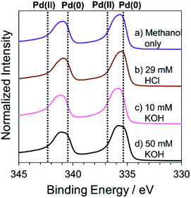 |
| | Fig. 7 High resolution XPS spectra of Pd structures prepared from the TOPO paste of Pd NPs by dipping into methanol (a) in the absence and the presence of (b) 29 mM HCl, (c) 10 mM KOH and (d) 50 mM KOH. | |
Table 1 The molar ratio of Pd(0) and Pd(II) in Pd structures determined by XPS
| Sintering agents |
Pd(0) (mol%) |
Pd(II) (mol%) |
| No addition (methanol only) |
48 |
52 |
| 29 mM HCl |
47 |
53 |
| 10 mM KOH |
39 |
61 |
| 50 mM KOH |
32 |
68 |
The crystallite sizes of porous Pd structures were evaluated by XRD (Fig. S6†). In all cases, the diffraction peaks at 2θ = 40°, 47° and 68° were identified as the (111), (200) and (220) planes of face-centered cubic Pd, respectively.47 The crystallite sizes were calculated based on the Scherrer equation using FWHM of the diffraction peaks at Pd (111). The calculated values of crystallite sizes are summarized in Table 2. In all cases (methanol only, CTAC, HCl and KOH), the crystallite size of porous Pd structures mostly remained compared with that of oleylamine-capped Pd NPs. These results indicate that the crystal reconstruction and growth in the neck hardly occurred in the sintering process. The similar FWHM of the diffraction peaks indicate that porous Pd structures were partly linked by residual organic compounds rather than the complete aggregation of Pd NPs. If Pd NPs severely aggregate, FWHM of the diffraction peaks should change.
Table 2 Crystallite sizes of oleylamine-capped Pd NPs and Pd structures prepared from the TOPO paste of Pd NPs by dipping into methanol containing a sintering agent
| Sintering agents |
Crystallite size ± standard error (nm) |
| Before RT chemical sintering (oleylamine-capped PdNPs) |
3.3 ± 0.1 |
| No addition (methanol only) |
3.1 ± 0.1 |
| 1.0 mM CTAC |
3.2 ± 0.1 |
| 29 mM HCl |
3.2 ± 0.1 |
| 10 mM KOH |
3.1 ± 0.1 |
| 50 mM KOH |
3.3 ± 0.1 |
The specific surface area of porous Pd structure in the case of 10 mM KOH was determined to be about 9 m2 g−1 by BET analysis. The value is much smaller than the calculated surface area (89 m2 g−1) of Pd NPs based on their average diameter (5.6 nm) and density of Pd (12 g cm−3). This result clearly shows that Pd NPs coalesce to form a porous structure.
Suzuki coupling reaction with porous Pd structures
In this section, the Suzuki coupling reaction of iodobenzene with 4-methylphenylboronic acid was investigated using porous Pd structures as heterogeneous catalysts (Scheme 1).28 The reactions were performed with KOH as a base in the presence of a 3 mol% Pd catalyst with respect to the substrate in methanol at 50 °C for 8 h. The conversion ratio (4-methylbiphenyl/(iodobenzene+4-methylbiphenyl)) was determined based on the peak area ratio at MCs obtained from GC-MS.
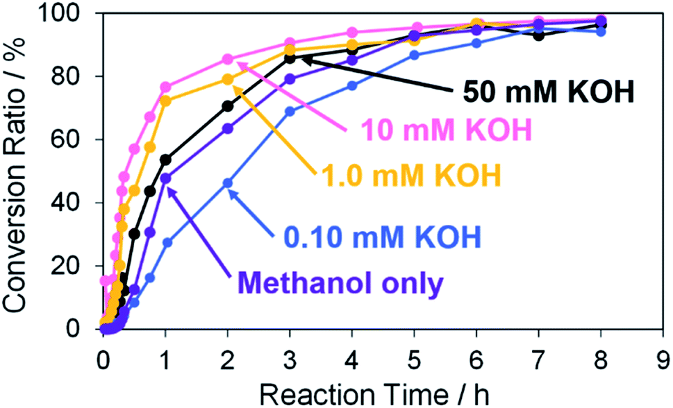
First, Pd structures prepared from the TOPO paste of Pd NPs by the RT chemical sintering with the various KOH concentrations were used as catalysts for the Suzuki coupling reaction. As for all catalysts, the coupling product was eventually obtained in ∼95% of the conversion ratio (Fig. 8). The catalytic ability of porous Pd structure was comparable to that of nanoporous Pd in the Tanaka' study (99%, 3 h).28 The slopes of the molar ratio against reaction time (≤3 h) were determined by linearly fitting the molar ratio (4-methylbiphenyl/iodobenzene) to reaction time (Fig. S7† and Table 3). The initial reaction rates were compared from the slopes. The reaction rate became larger with the increase of the KOH concentration (1.0–10 mM) in the RT chemical sintering. The increase of Pd methoxide and Pd–OH, which are generated with the aid of KOH, induces the activation of the Pd surface. Generally, Pd methoxide and Pd–OH promote transmetalation of boronic acid.1,43 However, the reaction rate in the case of 50 mM KOH was lower than that in the case of 10 mM KOH. In the case of 50 mM KOH, the coalescence of Pd NPs excessively proceeded (Fig. 4e) and then the surface area of the Pd structure became smaller due to their excess coalescence. This results in the decrease of the catalytic activity because the amount of Pd methoxide and Pd–OH on the surface of porous Pd structure decreases. In the TG measurements (Fig. 5), the weight loss in the case of 50 mM KOH decreased compared with that in the case of 10 mM KOH. This also supports the decrease in the amount of Pd methoxide and Pd–OH based on the excess coalescence in the case of 50 mM KOH.
 |
| | Fig. 8 Conversion ratios versus reaction time in the Suzuki coupling reaction of iodobenzene with 4-methylphenylboronic acid in the cases using Pd structures prepared from the TOPO paste of Pd NPs by dipping into methanol in the absence and presence of 0.10 mM, 1.0 mM, 10 mM and 50 mM KOH. | |
Table 3 Slopes of molar ratio (4-methylbiphenyl/iodobenzene) against reaction time (≤3 h) in the cases using Pd structures prepared by dipping into methanol in the presence of various KOH concentrations
| Sintering agents |
Slope (min−1) |
Coefficient of determination, R2 |
| No addition (methanol only) |
0.0177 |
0.934 |
| 0.10 mM KOH |
0.0098 |
0.903 |
| 1.0 mM KOH |
0.0378 |
0.974 |
| 10 mM KOH |
0.0513 |
0.993 |
| 50 mM KOH |
0.0273 |
0.926 |
Furthermore, a leaching test of Pd was performed by ICP-AES after the Suzuki coupling reaction with the porous Pd structure prepared by 10 mM KOH as the sintering agent. Dissolved Pd was detected in ∼0.0015 mol% (4.4 × 10⁻⁵ mmol of Pd). This result is comparable to the nanoporous Pd in the Tanaka' study (<0.02 mol%).28 Therefore, we can say that the leaching amount of Pd is quite small in the current catalytic system.
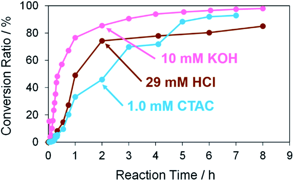
Next, Pd structures prepared from the TOPO paste of Pd NPs by the RT chemical sintering with other types of sintering agents, which are 1.0 mM CTAC and 29 mM HCl, were used as catalysts for the same Suzuki coupling reaction as above (Fig. 9). In both cases, the reaction rate was lower than that in the case of 10 mM KOH (Fig. S8† and Table 4). These results indicate that pre-activation of Pd by KOH affects the reactivity. In the cases of CTAC and HCl, Pd methoxide and Pd–OH are absent on the surface of porous Pd structures in advance. While the conversion ratio became finally 95% in the case of CTAC, the conversion ratio was 85% in the case of HCl. The Pd surface protonated in the sintering process may partly interrupt the formation of Pd methoxide and Pd–OH even in the Suzuki coupling reaction with KOH. As 10 mM KOH was the best sintering agent in this study, the porous Pd structure prepared from the TOPO paste of Pd NPs by the RT chemical sintering with the 10 mM KOH methanol solution was used for all of the following experiments.
 |
| | Fig. 9 Conversion ratios versus reaction time in the Suzuki coupling reaction of iodobenzene with 4-methylphenylboronic acid in the cases using Pd structures prepared from the TOPO paste of Pd NPs by dipping into methanol in the presence of 10 mM KOH, 29 mM HCl and 1.0 mM CTAC. | |
Table 4 Slopes of molar ratio (4-methylbiphenyl/iodobenzene) against reaction time (≤3 h) in the cases using Pd structures prepared by dipping into methanol in the presence of 10 mM KOH, 29 mM HCl and 1.0 mM CTAC
| Sintering agents |
Slope (min−1) |
Coefficient of determination, R2 |
| 10 mM KOH |
0.0513 |
0.993 |
| 29 mM HCl |
0.0157 |
0.933 |
| 1.0 mM CTAC |
0.0103 |
0.909 |
Reusability of porous Pd structure in the Suzuki coupling reaction
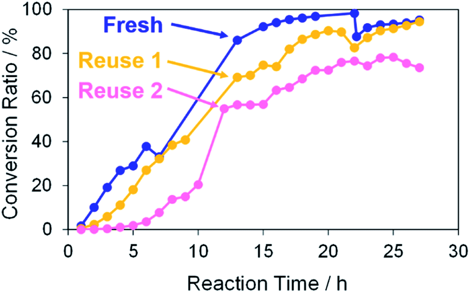
Finally, the reusability of the porous Pd structure was investigated in the Suzuki coupling reaction under the same reaction condition as above. The recovery process in the current catalytic reaction is very simple. The catalysts and products can be separated easily by centrifugation. The recovered catalyst was washed with methanol several times and then reused after drying without further treatments. In Fig. 10, the use numbers of catalysts were zero (fresh), one (reuse 1) and two (reuse 2). Indeed, 4-methylbiphenyl was obtained in a high conversion yield even using the reused catalyst reuse 1. However, the reaction rate of the reused catalyst was lower than that of “fresh”. This is because further coalescence of the porous Pd structure proceeded after the first Suzuki coupling reaction, as confirmed by SEM observation of the catalyst (Fig. S9†). It seemed that KOH in the reaction medium promoted the coalescence of porous Pd structures. In the case of “reuse 2”, the reaction rate decreased compared with those of “fresh” and “reuse 1”. Similarly, further coalescence of the porous Pd structure proceeded after the second Suzuki coupling reaction (Fig. S9†). Moreover, XPS analysis of the recovered porous Pd structure (reuse 1) was performed (Fig. S10†). In the spectrum of reuse 1, the peak of Pd(II) decreased and instead the peak of Pd(0) increased compared with that of fresh. This result indicates that Pd methoxide and Pd–OH on the surface of porous Pd structure were reduced to Pd(0) in the Suzuki coupling reaction.
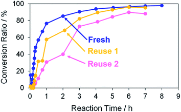 |
| | Fig. 10 Conversion ratios versus reaction time in the Suzuki coupling reaction of iodobenzene with 4-methylphenylboronic acid in methanol. The use numbers of catalysts were zero (fresh), one (reuse 1) and two (reuse 2). | |
The catalytic ability of the porous Pd structure was also examined in the Suzuki coupling reaction with other reactants and solvent. The reaction of 4-iodophenol with phenylboronic acid was performed with K2CO3 as a base in the presence of a 1 mol% porous Pd structure with respect to the substrate in water at RT for 27 h (Scheme 2),42 and 4-hydroxybiphenyl was obtained in 95% of the conversion ratio (Fig. 11). The catalytic activity of porous Pd structures was not affected by the reaction medium as opposed to that of the NP dispersion.48 This contrast result would be due to the non-dispersion of porous Pd structures and the absence of organic ligands which may prevent the surface of Pd NPs from interacting with reactants.
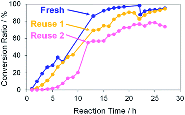 |
| | Fig. 11 Conversion ratios versus reaction time in the Suzuki coupling reaction of 4-iodophenol with phenylboronic acid in water. The use numbers of catalysts were zero (fresh), one (reuse 1) and two (reuse 2). | |
The porous Pd structure showed similar reusability to that described above. Whatever porous Pd structures were used, the reaction rate was lower than that of “fresh”. In the case of “reuse 2”, the conversion ratio significantly decreased. As in the above case, further coalescence of the porous Pd structure proceeded after the Suzuki coupling reaction (Fig. S11†).
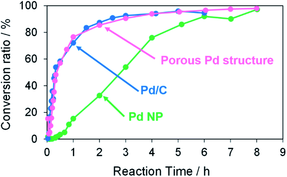
Performance comparison between porous Pd structure and Pd/C
The catalytic activity of the porous Pd structure was compared with those of commercial Pd/C (Pd 5 wt%) and oleylamine-capped Pd NP in the Suzuki coupling reaction as shown in Scheme 1. The reactions of iodobenzene with 4-methylphenylboronic acid were performed with KOH as a base in the presence of a 3 mol% Pd catalyst with respect to the substrate in methanol at 50 °C for 8 h (Fig. 12). The conversion ratio and reaction rate in the case using porous Pd structure were almost equal to that in the case using Pd/C (Fig. S12† and Table 5). In other words, the porous Pd structure showed similar catalytic activity to that of Pd/C. On the other hand, the reaction rate was significantly lower in the case using Pd NP. This result may be attributed to the fact that the surface of Pd NPs less effectively interacts with reactants due to the presence of oleylamine. All these results indicate that the RT chemical sintering makes the catalytic property of Pd more active.
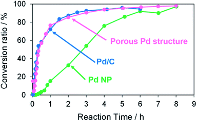 |
| | Fig. 12 Conversion ratios versus reaction time in the Suzuki coupling reaction of iodobenzene with 4-methylphenylboronic acid in the cases using porous Pd structure, commercial Pd/C, and oleylamine-capped Pd NP. | |
Table 5 Slopes of molar ratio (4-methylbiphenyl/iodobenzene) against reaction time (≤3 h) in the cases using Pd structures prepared by dipping into methanol in the presence of porous Pd structure, commercial Pd/C and oleylamine-capped Pd NP
| Catalysts |
Slope (min−1) |
Coefficient of determination, R2 |
| Porous Pd structure |
0.0513 |
0.993 |
| Pd/C |
0.0634 |
0.987 |
| Oleylamine-capped Pd NP |
0.0051 |
0.889 |
Conclusions
The porous Pd structures were prepared by the RT chemical sintering of the Pd NP paste. By using TOPO as a sacrificial template, porous Pd structures were obtained via dipping into methanol containing KOH or HCl as a sintering agent. The catalytic activities of porous Pd structures in the Suzuki coupling reaction increased with the increase of the KOH concentration in the sintering process. In contrast, the catalytic activity of the porous Pd structure obtained by HCl was low. These results indicate that pre-activation of porous Pd structures by KOH increases the catalytic activities. As opposed to the Pd NPs, the reaction solvent hardly affected the catalytic activity of porous Pd structures due to the absence of ligands. We expect that the porous Pd structure obtained by this method is a good candidate for environmentally-friendly heterogeneous catalysts and thus this method could be widely applicable to the preparation of various porous metal structures.
Author contributions
S. O., M. W., T. T. and Y. K. performed experiments and S. O. analyzed data. S. O. and Y. N. designed research and S. O. wrote the paper. Y. N., T. T. and S. Y. revised the paper.
Conflicts of interest
There are no conflicts to declare.
References
- D. Peral, F. Gómez-Villarraga, X. Sala, J. Pons, J. C. Bayón, J. Ros, M. Guerrero, L. Vendier, P. Lecante and J. García-Antón, Catal. Sci. Technol., 2013, 3, 475–489 RSC.
- S. Hosokawa, T. Shibano, H. Koga, M. Matsui, H. Asakura, K. Teramura, M. Okumura and T. Tanaka, ChemCatChem, 2020, 12, 4276–4280 CrossRef CAS.
- C. Bianchini and P. K. Shen, Chem. Rev., 2009, 109, 4183–4206 CrossRef CAS PubMed.
- N. Miyaura and A. Suzuki, Chem. Rev., 1995, 95, 2457–2483 CrossRef CAS.
- A. F. Littke and G. C. Fu, Angew. Chem., Int. Ed., 2002, 41, 4176–4211 CrossRef CAS PubMed.
- Y. Li, E. Boone and M. A. El-Sayed, Langmuir, 2002, 18, 4921–4925 CrossRef CAS.
- C. C. Cassol, A. P. Umpierre, G. Machado, S. I. Wolke and J. Dupont, J. Am. Chem. Soc., 2005, 127, 3298–3299 CrossRef CAS PubMed.
- T. Yonezawa, K. Kawai, H. Kawakami and T. Narushima, Bull. Chem. Soc. Jpn., 2016, 89, 1230–1232 CrossRef CAS.
- D. Chen, W. Yang, L. Jiao, L. Li, S.-H. Yu and H.-L. Jiang, Adv. Mater., 2020, 32, 2000041 CrossRef CAS.
- M. N. Shaikh, RSC Adv., 2019, 9, 28199–28206 RSC.
- X. Shao, X. Miao, X. Yu, W. Wang and X. Ji, RSC Adv., 2020, 10, 9414–9419 RSC.
- Y. Yang, H. Niu, W. Zhao, L. Xu, H. Zhang and Y. Cai, RSC Adv., 2020, 10, 29402–29407 RSC.
- H. R. Choi, H. Woo, S. Jang, J. Y. Cheon, C. Kim, J. Park, K. H. Park and S. H. Joo, ChemCatChem, 2012, 4, 1587–1594 CrossRef CAS.
- C. D. Gu, X. J. Xu and J. P. Tu, J. Phys. Chem. C, 2010, 114, 13614–13619 CrossRef CAS.
- Z. Li, J. Xu, X. Gu, K. Wang, W. Wang, X. Zhang, Z. Zhang and Y. Ding, ChemCatChem, 2013, 5, 1705–1708 CrossRef CAS.
- S. Li, C.-L. Chien and P. C. Searson, Chem. Mater., 2004, 16, 3125–3129 CrossRef.
- X. Niu, M. Lan, H. Zhao and C. Chen, Anal. Chem., 2013, 85, 3561–3569 CrossRef CAS PubMed.
- Q. Chen, X. Zhang, S. Su, Z. Xu, N. Li, Y. Li, H. Zhou, M. Bao, Y. Yamamoto and T. Jin, ACS Catal., 2018, 8, 5901–5906 CrossRef CAS.
- A. J. Welch, J. S. DuChene, G. Tagliabue, A. Davoyan, W.-H. Cheng and H. A. Atwater, ACS Appl. Energy Mater., 2019, 2, 164–170 CrossRef CAS.
- A. Kloke, F. von Stetten, R. Zengerle and S. Kerzenmacher, Adv. Mater., 2011, 23, 4976–5008 CrossRef CAS PubMed.
- E.-M. Steyskal, Z. Qi, P. Pölt, M. Albu, J. Weissmüller and R. Würschum, Langmuir, 2016, 32, 7757–7764 CrossRef CAS PubMed.
- S. Cherevko, N. Kulyk and C.-H. Chung, Nanoscale, 2012, 4, 103–105 RSC.
- Z. Li, S. Lin, L. Ji, Z. Zhang, X. Zhang and Y. Ding, Catal. Sci. Technol., 2014, 4, 1734–1737 RSC.
- T. T. H. Hoang, S. Verma, S. Ma, T. T. Fister, J. Timoshenko, A. I. Frenkel, P. J. A. Kenis and A. A. Gewirth, J. Am. Chem. Soc., 2018, 140, 5791–5797 CrossRef CAS PubMed.
- J. Son, S. Cho, C. Lee, Y. Lee and J. H. Shim, Langmuir, 2014, 30, 3579–3588 CrossRef CAS.
- L. Chen, H. Guo, T. Fujita, A. Hirata, W. Zhang, A. Inoue and M. Chen, Adv. Funct. Mater., 2011, 21, 4364–4370 CrossRef CAS.
- C. Li, M. Iqbal, J. Lin, X. Luo, B. Jiang, V. Malgras, K. C.-W. Wu, J. Kim and Y. Yamauchi, J. Am. Chem. Soc., 2018, 51, 1764–1773 CAS.
- S. Tanaka, T. Kaneko, N. Asao, Y. Yamamoto, M. Chen, W. Zhang and A. Inoue, Chem. Commun., 2011, 47, 5985–5987 RSC.
- S. Magdassi, M. Grouchko, O. Berezin and A. Kamyshny, ACS Nano, 2010, 4, 1943–1948 CrossRef CAS PubMed.
- M. Grouchko, A. Kamyshny, C. F. Mihailescu, D. F. Anghel and S. Magdassi, ACS Nano, 2011, 5, 3354–3359 CrossRef CAS PubMed.
- L. Shi, M. Layani, X. Cai, H. Zhao, S. Magdassi and M. Lan, Sens. Actuators, B, 2018, 256, 938–945 CrossRef CAS.
- P. Peng, L. Li, W. Guo, Z. Hui, J. Fu, C. Jin, Y. Liu and Y. Zhu, J. Phys. Chem. C, 2018, 122, 2704–2711 CrossRef CAS.
- Y. Xiao, Z. H. Zhang, M. Yang, H. F. Yang, M. Y. Li and Y. Cao, Mater. Lett., 2018, 222, 16–20 CrossRef CAS.
- S. Okada, Y. Nakahara, M. Watanabe, T. Tamai and S. Yajima, J. Nanosci. Nanotechnol., 2019, 19, 4565–4570 CrossRef CAS PubMed.
- S. Okada, Y. Nakahara, M. Watanabe, T. Tamai, Y. Kobayashi and S. Yajima, J. Phys. Chem. C, 2019, 123, 14118–14125 CrossRef CAS.
- S. Okada, Y. Nakahara, M. Watanabe, T. Tamai, Y. Kobayashi and S. Yajima, Bull. Chem. Soc. Jpn., 2021, 94, 1616–1624 CrossRef CAS.
- F.-X. Felpin, T. Ayad and S. Mitra, Eur. J. Org. Chem., 2006, 2006, 2679–2690 CrossRef.
- L. Yin and J. Liebscher, Chem. Rev., 2007, 107, 133–173 CrossRef CAS PubMed.
- M. Lamblin, L. Nassar-Hardy, J.-C. Hierso, E. Fouquet and F.-X. Felpin, Adv. Synth. Catal., 2010, 352, 33–79 CrossRef CAS.
- A. Ohtaka, M. Kawase, S. Aihara, Y. Miyamoto, A. Terada, K. Nakamura, G. Hamasaka, Y. Uozumi, T. Shinagawa, O. Shimomura and R. Nomura, ACS Omega, 2018, 3, 10066–10073 CrossRef CAS PubMed.
- V. Mazumder and S. Sun, J. Am. Chem. Soc., 2009, 131, 4588–4589 CrossRef CAS PubMed.
- H. Sakurai, T. Tsukuda and T. Hirao, J. Org. Chem., 2002, 67, 2721–2722 CrossRef CAS PubMed.
- C. Amatore, A. Jutand and G. L. Duc, Chem.–Eur. J., 2011, 17, 2492–2503 CrossRef CAS PubMed.
- M. Yamamoto, H. Kakiuchi, Y. Kashiwagi, Y. Yoshida, T. Ohno and M. Nakamoto, Bull. Chem. Soc. Jpn., 2010, 83, 1386–1391 CrossRef CAS.
- J. Batista, A. Pintar, D. Mandrino, M. Jenko and V. Martin, Appl. Catal., A, 2001, 206, 113–124 CrossRef CAS.
- S. Yamamoto, H. Kinoshita, H. Hashimoto and Y. Nishina, Nanoscale, 2014, 6, 6501–6505 RSC.
- S. Fujii, S. Matsuzawa, Y. Nakamura, A. Ohtaka, T. Teratani, K. Akamatsu, T. Tsuruoka and H. Nawafune, Langmuir, 2010, 26, 6230–6239 CrossRef CAS PubMed.
- S. Janani, P. Stevenson and A. Veerappan, Colloids Surf., B, 2014, 117, 528–533 CrossRef CAS PubMed.
|
| This journal is © The Royal Society of Chemistry 2022 |
Click here to see how this site uses Cookies. View our privacy policy here. 
 Open Access Article
 This Open Access Article is licensed under a Creative Commons Attribution-Non Commercial 3.0 Unported Licence
 a,
Yoshio Nakahara
a,
Yoshio Nakahara