
 Open Access Article
 This Open Access Article is licensed under a Creative Commons Attribution-Non Commercial 3.0 Unported Licence
Transformation of the coordination nanostructures of 4,4′,4′′-(1,3,5-triazine-2,4,6-triyl) tribenzoic acid molecules on HOPG triggered by the change in the concentration of metal ions†
Sihao Li,
Caimei Gong,
Yuyang Zhang,
Shizhang Fu,
Zhongping Wang,
Yan Lu,
Siyi Gu,
Xiaoqing Liu * and
Li Wang*
* and
Li Wang*
Department of Physics, Nanchang University, Nanchang 330031, China. E-mail: liuxiaoqing@ncu.edu.cn; liwang@ncu.edu.cn
First published on 31st January 2022
Abstract
The modulation effects of Cu2+/Fe3+ ions on the hydrogen-bonded structure of 4,4′,4′′-(1,3,5-triazine-2,4,6-triyl) tribenzoic acid (TATB) on a HOPG surface have been investigated at the liquid–solid interface by scanning tunneling microscopy (STM). STM observations directly demonstrated that the self-assembled honeycomb network of TATB has been dramatically transformed after introducing CuCl2/FeCl3 with different concentrations. The metal–organic coordination structures are formed due to the incorporation of the Cu2+/Fe3+ ions. Interestingly, a Cu2+ ion remains coordinated to two COOH groups and only the number of COOH groups involved in coordination doubles when the concentration of Cu2+ ions doubled. A Fe3+ ion changes from coordination to three COOH groups to two COOH groups after increasing the concentration of Fe3+ ions in a mixed solution. Such results suggest that the self-assembled structures of TATB molecules formed by metal–ligand coordination bonds can be effectively adjusted by regulating the concentration of metal ions in a mixed solution, which has rarely been reported before. It explains that the regulatory effect of concentration leads to the diversity of molecular architectures dominated by coordination bonds.
Introduction
Metal–organic coordination structures are materials comprising reticular metal centers and organic linkers in which the two constituents bind with each other via metal–ligand coordination interactions. The coordination-driven molecular self-assembly of nanostructures on solid surfaces has attracted much attention owing to the potential applications of such structures in nanodevices and nanopatterning in the future.1–4 Recently, coordination interaction has been used in the direct preparation of novel nanostructures ranging from clusters,5,6 1D chains or polymers,7–10 to 2D coordination frameworks,11–14 and even 3D structures.15–17 Moreover, their composition, morphology and properties have been well proved, and have opened up specific and targeted application in the areas of chemical and materials sciences.18,19 However, few studies have focused on regulating the coordination structures which involves changing the metal species for coordination, and more importantly, the concentrations of metal ions used to form the coordination structures.A variety of studies have demonstrated the coordination nanostructures by altering organic ligands, such as carboxylate,3,5,12,18 hydroxyl,14,20,21 pyridine,9,22–25 and triazine.26–30 The triazine derivatives are important in a range of areas as ligands for supramolecular self-assembly of more complex mixed layers, hence it may be interesting to study the coordination properties of the triazine derivatives. In this article, we fabricated different coordination nanostructures by 4,4′,4′′-(1,3,5-triazine-2,4,6-triyl) tribenzoic acid (TATB) molecules coordinating with Cu2+ or Fe3+ ion with different concentrations on highly oriented pyrolytic graphite (HOPG) surface. Scanning tunneling microscopy (STM) images directly demonstrated the transformation of the nanostructure from self-assembled honeycomb networks formed by TATB molecules via hydrogen bonding into coordination nanostructures formed through the TATB molecules coordinated with metal ions. Moreover, by varying the concentrations of Cu2+ or Fe3+ ions, coordination structures with different shapes and sizes have been fabricated, which illustrates the concentrations and valence states of the metal ions plays important roles in the coordination nanostructures.
Experimental
Sample preparation
4,4′,4′′-(1,3,5-Triazine-2,4,6-triyl) tribenzoic acid (TATB) molecules used in this work weren't further purified after purchased from Ark Pharm. Ferric chloride and copper chloride were purchased from DAMAO. Stock solutions of 30 mL each of TATB and metal chloride were prepared by dissolving these reagents in nonanoic acid purchased from Aladdin. The concentrations of TATB, CuCl2 and FeCl3 were 2.2 × 10⁻⁵ M, 4.4 × 10⁻⁵ M and 5.8 × 10⁻⁶ M, respectively. The molar ratio of TATB to metal chloride in the final product was controlled by the deposited volumes. STM samples were prepared by dropping about 3.0 μL of the solutions on a freshly cleaved HOPG substrate. Then, the samples were kept at room temperature for about 0.5 h. Finally, the samples were investigated by STM at the liquid/solid interface.STM measurements
The STM measurements were performed under atmospheric conditions, ambient temperature of about 25 °C. STM tips were made by cutting Pt/Ir (80/20) wire (California Fine Wire Co., Grover Beach, CA). All the STM images were acquired on a Pico-SPM (Molecular Imaging, Agilent Technology) scanning tunneling microscope operating in constant-current mode, the imaging parameters are stated in the figure captions, and extracted from raw data files using Pico Image Basic 6.2 program (Agilent, USA). To avoid possible experimental artifacts, each STM sample was repeatedly measured with different tips. The drift was calibrated using the underlying graphite lattice as a reference. High-resolution STM (HR-STM) images were low-pass-filtered.Constructed and computational details
The above structures are calculated by first-principles density functional theory (DFT), as implemented in the Vienna Ab initio Simulation Package (VASP), with the PBE generalized-gradient exchange and correlation functional. A plane-wave basis set with a kinetic energy cutoff of 400 eV is adopted and the van der Waals interaction is considered with the optB86b-vdW method. A 1 × 1 × 1 k-mesh was adopted for geometry optimization and total energy calculations. For structure relaxations, all atoms were fully relaxed until the residual force per atom was less than 0.02 eV Å−1.Results and discussion
After depositing a droplet of nonanoic acid solution containing TATB molecules onto a freshly cleaved HOPG surface, STM images show that TATB molecules form a uniform monolayer with molecules lying flat on the surface. Fig. 1a shows the typical honeycomb network of TATB on HOPG. The high resolution STM image in Fig. 1b revealed that each TATB molecule has a three-clover structure, where each clover can be assigned to a benzoic acid moiety on the bridge arm of TATB. The group composed of six TATB molecules forms a hexagonal network, and the unit cell of the assembly is marked in Fig. 1b (rhomboid in white solid line). The vectors for the unit cell, a and b, is respectively of (3.68 ± 0.2) Å and (3.68 ± 0.2) Å and the angle α between the vectors is (60 ± 1°). The proposed model of the supramolecular honeycomb network shown in Fig. 1c indicates that each TATB molecule can interact with three adjacent molecules by the O–H⋯O hydrogen bonds (as illustrated by yellow dashed lines in Fig. 1c). Simulated STM image in the Fig. 1d matches well with the STM result. We measured the distance of O–H⋯O hydrogen bonds is approximately 2.64 Å, which are in good agreement with the lengths as previously reported in organic crystals.31 | ||
| Fig. 1 The STM images and simulated STM images of TATB molecules on HOPG. (a) The large-scale STM image of self-assembly structure. Set point: I = 0.5 nA, V = −1 V. (b) High resolution STM image of honeycomb network. Set point: I = 0.6 nA, V = −0.8 V. (c) The fully relaxed model of the honeycomb network. Yellow dotted line: O–H⋯O hydrogen bond. (d) Simulated STM image of (c). | ||
When the nonanoic acid containing CuCl2 and TATB (the molar ratio was adjusted to 1![[thin space (1/6-em)]](https://www.rsc.org/images/entities/char_2009.gif) :2) is deposited on an HOPG surface, a well-ordered assembling structure composed of parallel chains labeled by white dotted line is found as shown in Fig. 2a, which is quite different from the honeycomb network composed of pure TATB molecules. Close examination in Fig. 2b reveals that these chains consist of some herringbone-like features and some dots. Since this structure only emerged after the introduction of CuCl2, these herringbone-like features and dots were attributed to TATB molecules and Cu2+ ions, respectively. The arrangement diagram of TATB molecules and Cu2+ was superimposed on Fig. 2b, in which the red graphics mark the distribution of TATB molecules and the light blue circles mark the arrangement of Cu2+ ions. Fig. 2c illustrates the corresponding optimized structure model. Two TATB molecules are bridged by Cu2+ ion to form coordination dimers, and the dimers are connected by two C–H⋯O hydrogen bonds as illustrated by green dashed lines in Fig. 2c. Simulated STM images in Fig. 2d demonstrate that the C–H⋯O hydrogen bond lengths are (3.0 ± 0.2) Å and the O–Cu–O coordination bond lengths are (4.0 ± 0.3) Å, which is consistent with the STM result.
:2) is deposited on an HOPG surface, a well-ordered assembling structure composed of parallel chains labeled by white dotted line is found as shown in Fig. 2a, which is quite different from the honeycomb network composed of pure TATB molecules. Close examination in Fig. 2b reveals that these chains consist of some herringbone-like features and some dots. Since this structure only emerged after the introduction of CuCl2, these herringbone-like features and dots were attributed to TATB molecules and Cu2+ ions, respectively. The arrangement diagram of TATB molecules and Cu2+ was superimposed on Fig. 2b, in which the red graphics mark the distribution of TATB molecules and the light blue circles mark the arrangement of Cu2+ ions. Fig. 2c illustrates the corresponding optimized structure model. Two TATB molecules are bridged by Cu2+ ion to form coordination dimers, and the dimers are connected by two C–H⋯O hydrogen bonds as illustrated by green dashed lines in Fig. 2c. Simulated STM images in Fig. 2d demonstrate that the C–H⋯O hydrogen bond lengths are (3.0 ± 0.2) Å and the O–Cu–O coordination bond lengths are (4.0 ± 0.3) Å, which is consistent with the STM result.
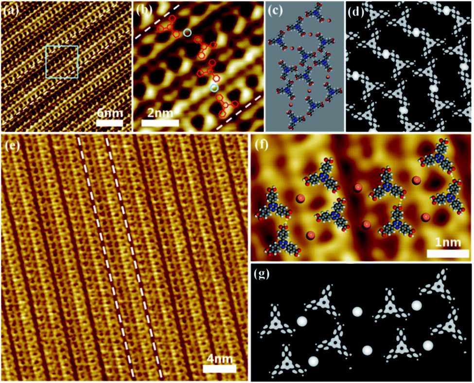 | ||
| Fig. 2 (a) STM image of Cu2+/TATB (Cu2+:TATB = 1:2) self-assembled chains on HOPG surface. Set point: I = 0.55 nA, V = −0.6 V. (b) The enlarged image of the area marked by the blue square in (a). The three-clover graphics label TATB molecules, and the blue circle represents the copper ions. (c) Schematic model of 1:2 Cu2+/TATB chain. (d) Simulated STM image of (c). (e) STM image of Cu2+/TATB (Cu2+:TATB = 1:1) self-assembled structures on HOPG surface. Set point: I = 0.57 nA, V = −0.6 V. (f) High resolution STM image of 1:1 Cu2+/TATB chain superimposed with the schematic model. (g) Simulated STM image of (f). Blue dotted line: C–H⋯O hydrogen bond; yellow dotted line: O–H⋯O hydrogen bond. | ||
If we tune the molar ratio of CuCl2/TATB from 1:2 to 1:1, another parallel chain labeled by white dotted line were obtained as shown in Fig. 2e. An overview image of the new chains reveals that such nanostructure is different with that above. Close examination in Fig. 2f reveals that these chains consist of some three-clover features and some dots. Similar to the above, these three-clover features and dots are designated as TATB molecules and Cu2+ ions, respectively. The optimized structure model superimposed on Fig. 2f illustrates two TATB molecules are bridged by Cu2+ ion to form coordination dimers, and the dimers on the same chain are connected by two O–H⋯O hydrogen bonds while the dimers on adjacent chains interact through O–Cu–O coordination bond. The corresponding simulated STM image in Fig. 2g coincides well with the experimental STM image in Fig. 2f and shows that O–H⋯O hydrogen bond lengths are approximately 2.6 ± 0.2 Å and O–Cu–O coordination bond lengths are approximately 4.0 ± 0.2 Å, which confirms that the O–Cu–O coordination bonds are the main driving force within the structure. Compared with the above chains, the dimers are also formed by O–Cu–O coordination bond. However, the driving force between the dimers on the adjacent chain changes from C–H⋯O hydrogen bond into O–Cu–O coordination bond, which results to the transformation of self-assembly structure of the chains. The result shows that the polymorphic self-assembly of TATB molecules and Cu2+ is realized on HOPG by increasing the concentration of metal ions.
Similar structural transformation was obtained by depositing a mixed solution of TATB molecules and FeCl3 on HOPG. Fig. 3a shows the typical STM image of the assembled structure formed by depositing a mixture of TATB molecules and FeCl3 with a molar ratio of 1:1 on the HOPG surface. The estimated coverage of iron on the surface is about 1.67 ion per nm2. It can be seen that the building blocks for the structure are the trimers of TATB molecules in which one bright dot is surrounded by three bright clover-shaped structures with a local threefold symmetry as marked by a green dotted circle in Fig. 3a. As the proposed model superimposed on the STM image in Fig. 3b, the central small bright spot is attributed to Fe3+ and the three clover-shaped bright spots represents three TATB molecules. In this model of TATB/Fe3+ trimers, three carboxyl groups linked with one Fe3+ ion through metal coordination, and the three carboxyl groups are connected to each other through O–H⋯O hydrogen bonds. The corresponding simulated STM image in Fig. 3c is consistent with the experimental STM image in Fig. 3b and shows that the length of three Fe–O coordination bonds between three oxygen atoms within the carboxyl groups of TATB molecules and the centered Fe3+ ion are 2.110 Å, 2.089 Å and 2.106 Å respectively, which is in good agreement with typical length of Fe–O bond in previous studies.
 | ||
| Fig. 3 (a) STM image of Fe3+/TATB (Fe3+:TATB = 1:1) self-assembled line network on HOPG surface. Fe ions in the STM image is marked with a solid green circle. Set point: I = 0.7 nA, V = −0.8 V. (b) The enlarged image of the area denoted by the green circle in (a) superimposed with the schematic model of TATB/Fe3+ trimers. (c) Simulated STM images of (b). (d) STM image of Fe3+/TATB (Fe3+:TATB = 3:2) self-assembled chains on HOPG surface. Set point: I = 0.7 nA, V = −0.6 V. (e) The enlarged image and schematic model of the (Fe3+:TATB = 3:2) chain in the white square of (d). Fe ions in the STM image is marked with a solid red circle. Yellow dashed line: O–H⋯O hydrogen bond. (f) Simulated STM images of (e). | ||
After adjusting the molar ratio of FeCl3:TATB to 3:2, the self-assembly structure of TATB molecules and Fe3+ ions have undergone an obvious change from trimer structure to chain structure (Fig. 3d). Close examination in Fig. 3e allows us to propose the structure model: TATB molecules between adjacent chains interact via O–Fe–O coordination bond, while TATB molecules on the same chain are contact with each other by O–H⋯O hydrogen bonds. In the Fig. 3e, Fe3+ ions are marked by small brown dots and red circles, and TATB molecules are presented with optimized structural formulas. Obviously, O–Fe–O coordination bond plays a dominant role in the assembly structure. It is worth noting that one Fe3+ ion coordinates with two carboxyl groups instead of three carboxyl groups mentioned above, as a consequence, the self-assembly structure of TATB and FeCl3 changes from network into chain. Fig. 3f shows the corresponding simulated STM image obtained by DFT calculation.
The DFT calculation provides an insight into the adsorption of Cu2+ or Fe3+ ion in the self-assembled structures of TATB molecules via metal–organic coordination bonding. Fig. 4 illustrates seven potential sites of metal adsorbed on TATB dimer and the DFT results for seven adsorption sites are listed in Table 1. The corresponding optimized structure models and STM simulation images are shown in ESI Fig. 1 and 2.† In the system of Cu2+/Fe3+ and TATB dimer, the lowest total energy is ES7 and ES5, respectively, indicating that the best adsorption site of Cu2+ is S7 and that of Fe3+ is S5. On this basis, DFT calculations are performed on four systems with multiple potential configurations according to our experimental system mentioned above as shown in Fig. 5. The DFT results demonstrate that the configurations S4, S8, S12 and S16 have the lowest total energy of −1359.54 eV, −1362.14 eV, −686.99 eV and −692.16 eV in the system with the molar ratio Cu2+/TATB of 1:2, Cu2+/TATB of 1:1, Fe3+/TATB of 1:1 and Fe3+/TATB of 3:2, respectively. Comparing several configurations in each system, it is easy to find that Cu2+/Fe3+ ions are all coordinated with TATB molecules in configurations S4, S8, S12 and S16 rather than one or more Cu2+/Fe3+ ions only adsorbed on TATB molecules in other configurations. Significantly, the configuration in S4, S8, S12 and S16 is in good agreement with the corresponding model proposed in each system, which further proves the correctness of our proposed model.
 | ||
| Fig. 4 Seven potential sites (S1, S2, S3, S4, S5, S6 and S7) of Cu2+/Fe3+ adsorbed on TATB dimer. | ||
| Energy | Cu | Fe |
|---|---|---|
| ES1 | −678.26 | −681.18 |
| ES2 | −678.35 | −679.2 |
| ES3 | −678.73 | −680.86 |
| ES4 | −678.410 | −682.35 |
| ES5 | −678.00 | −682.38 |
| ES6 | −678.33 | −681.63 |
| ES7 | −679.18 | −681.64 |
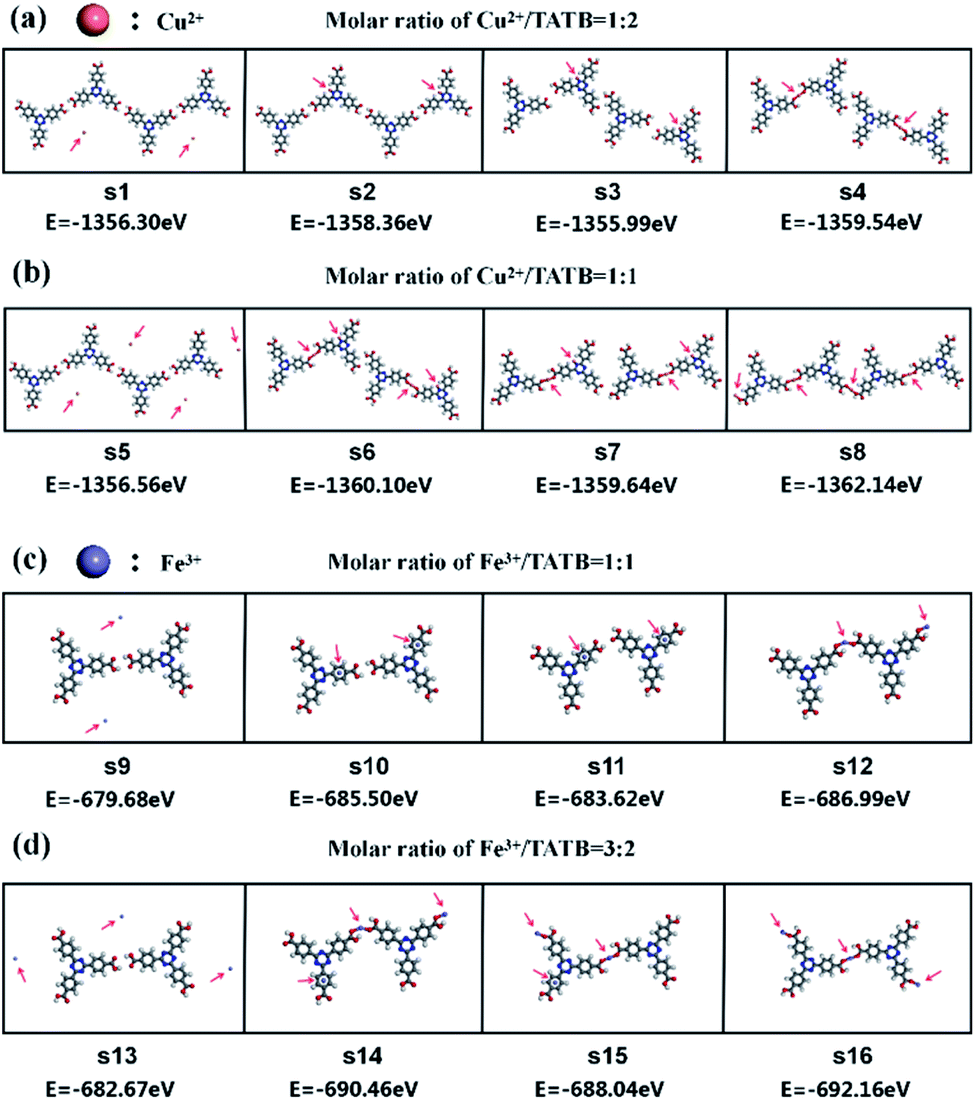 | ||
| Fig. 5 DFT calculation results of the total energy for the system of Cu2+/Fe3+ and TATB dimer. (a) The total system energy for 1:2 Cu2+/TATB structure. (b) The total system energy for 1:1 Cu2+/TATB structure. (c) The total system energy for 1:1 Fe3+/TATB structure. (d) The total system energy for 3:2 Fe3+/TATB structure. The red arrows indicate the sites of Cu2+ or Fe3+ ions. | ||
Conclusions
The self-assembled hydrogen-bonded molecular network of TATB has been dramatically transformed after introducing CuCl2/FeCl3 with different concentrations. The deposited monolayer of TATB molecules shows honeycomb structure. The Cu2+/Fe3+ ions can incorporate with TATB molecule via metal–organic coordination to form new structures, and the self-assembled structures of TATB molecules on HOPG formed by metal–ligand coordination bond can by effectively adjusted by tuning the concentration of metal ions in mixed solution.Author contributions
X. L. and L. W. conceived and designed the experiment, discussed and analyzed data, and wrote the manuscript. S. L. and X. L. performed sample preparation and STM. S. L., S. G., X. L., Y. Z. and Z. W. analyzed the data. S. L., S. F., C. G., and Y. L. performed the DFT calculations and theoretical analyses. All authors discussed the results and commented on the manuscript.Conflicts of interest
There are no conflicts to declare.Acknowledgements
This work was financially supported by National Natural Science Foundation of China (Grant No. 11727902, 61864007, 22162018, 61927813 and 11774341) and Natural Science Foundation of Jiangxi Province (20202BABL203013).Notes and references
- S. Xing, Z. Zhang, X. Fei, W. Zhao, R. Zhang, T. Lin, D. Zhao, H. Ju, H. Xu, J. Fan, J. Zhu, Y. Q. Ma and Z. Shi, Nat. Commun., 2019, 10, 70 CrossRef CAS PubMed
.
- T. Sirtl, S. Schlogl, A. Rastgoo-Lahrood, J. Jelic, S. Neogi, M. Schmittel, W. M. Heckl, K. Reuter and M. Lackinger, J. Am. Chem. Soc., 2013, 135, 691–695 CrossRef CAS PubMed
- W. Li, J. Jin, X. Leng, Y. Lu, X. Liu and L. Wang, J. Phys. Chem. C, 2016, 120, 12605–12610 CrossRef CAS
- X. Qiu, X. Xiang, T. Liu, H. Huang and Y. Hu, Process Biochem., 2020, 95, 47–54 CrossRef CAS
- Q. Li, L. Yan, Z. Wang, Y. Lu, S. Wei, X. Liu and L. Wang, J. Chem. Phys., 2020, 152, 044704 CrossRef CAS PubMed
- X. Meng, E. Kolodzeiski, X. Huang, A. Timmer, B. Schulze Lammers, H. Y. Gao, H. Mönig, L. Liu, W. Xu, S. Amirjalayer, D. Zhu and H. Fuchs, ChemNanoMat, 2020, 6, 1479–1484 CrossRef CAS
- M. Telychko, J. Su, A. Gallardo, Y. Gu, J. I. Mendieta-Moreno, D. Qi, A. Tadich, S. Song, P. Lyu, Z. Qiu, H. Fang, M. J. Koh, J. Wu, P. Jelinek and J. Lu, Angew. Chem., Int. Ed., 2019, 58, 18591–18597 CrossRef CAS PubMed
- J. F. Schultz, B. Yang and N. Jiang, J. Chem. Phys., 2021, 154, 044703 CrossRef CAS PubMed
- S. Xing, Z. Zhang, H. Liang, B. Sun, H. Xu, J. Fan, Y. Q. Ma and Z. Shi, Langmuir, 2020, 36, 6286–6291 CrossRef CAS PubMed
- J. Li, L. Solianyk, N. Schmidt, B. Baker, S. Gottardi, J. C. Moreno Lopez, M. Enache, L. Monjas, R. van der Vlag, R. W. A. Havenith, A. K. H. Hirsch and M. Stohr, J. Phys. Chem. C, 2019, 123, 12730–12735 CrossRef CAS PubMed
- Y. Guo, A. Nuermaimaiti, N. D. Kjeldsen, K. V. Gothelf and T. R. Linderoth, J. Am. Chem. Soc., 2020, 142, 19814–19818 CrossRef CAS PubMed
- A. Dmitriev, H. Spillmann, N. Lin, J. V. Barth and K. Kern, Angew. Chem., 2003, 115, 2774–2777 CrossRef
- C. Wäckerlin and K.-H. Ernst, J. Phys. Chem. C, 2021, 125, 13343–13349 CrossRef
- A. Rochefort, L. Vernisse, A. C. Gómez-Herrero, C. Sánchez-Sánchez, J. A. Martín-Gago, F. Chérioux, S. Clair, J. Coraux and J. I. Martínez, J. Phys. Chem. C, 2021, 125, 17333–17341 CrossRef CAS
- L. Shao, B. Hua, X. Hu, D. Stalla, S. P. Kelley and J. L. Atwood, J. Am. Chem. Soc., 2020, 142, 7270–7275 CrossRef CAS PubMed
- L. Shao, X. Hu, K. Sikligar, G. A. Baker and J. L. Atwood, Acc. Chem. Res., 2021, 54, 3191–3203 CrossRef CAS PubMed
- Y. Jin, Q. Zhang, Y. Zhang and C. Duan, Chem. Soc. Rev., 2020, 49, 5561–5600 RSC
- S. O. Parreiras, D. Moreno, B. Cirera, M. A. Valbuena, J. I. Urgel, M. Paradinas, M. Panighel, F. Ajejas, M. A. Nino, J. M. Gallego, M. Valvidares, P. Gargiani, W. Kuch, J. I. Martinez, A. Mugarza, J. Camarero, R. Miranda, P. Perna and D. Ecija, Small, 2021, e2102753 CrossRef PubMed
- X. Bi, Y. Zhang, F. Zhang, S. Zhang, Z. Wang and J. Jin, ACS Appl. Mater. Interfaces, 2020, 12, 49101–49110 CrossRef CAS PubMed
- X. Chen, L. Shang, H. Cui, H. Yang, L. Liu, Y. Ren and J. Wang, CrystEngComm, 2020, 22, 5900–5913 RSC
- U. Manna and G. Das, Coord. Chem. Rev., 2021, 427, 213547 CrossRef CAS
- V. Velasco, D. Aguila, L. A. Barrios, I. Borilovic, O. Roubeau, J. Ribas-Arino, M. Fumanal, S. J. Teat and G. Aromi, Chem. Sci., 2015, 6, 123–131 RSC
- A. Rajput and R. Mukherjee, Coord. Chem. Rev., 2013, 257, 350–368 CrossRef CAS
- D. Urankar, B. Pinter, A. Pevec, F. De Proft, I. Turel and J. Kosmrlj, Inorg. Chem., 2010, 49, 4820–4829 CrossRef CAS PubMed
- T. R. Umbach, M. Bernien, C. F. Hermanns, L. L. Sun, H. Mohrmann, K. E. Hermann, A. Krüger, N. Krane, Z. Yang, F. Nickel, Y.-M. Chang, K. J. Franke, J. I. Pascual and W. Kuch, Phys. Rev. B: Condens. Matter Mater. Phys., 2014, 89, 235409 CrossRef
- N. Shekarlab, R. Ghorbani-Vaghei and S. Alavinia, J. Organomet. Chem., 2021, 949, 121971 CrossRef CAS
- N. Portolés-Gil, A. M. López-Periago, A. Borrás, J. Fraile, E. Solano, O. Vallcorba, J. G. Planas, J. A. Ayllón and C. Domingo, Cryst. Growth Des., 2020, 20, 3304–3315 CrossRef
- T. Schäfer, A. E. Sedykh, J. Becker and K. Müller-Buschbaum, Z. Anorg. Allg. Chem., 2020, 646, 1555–1562 CrossRef
- S. Rajak, M. Mohan, A. A. Tremblay, T. Maris, S. Leal do Santos, E. C. Venancio, S. Ferreira Santos and A. Duong, ACS Omega, 2019, 4, 2708–2718 CrossRef CAS PubMed
- F. Marandi, K. Moeini, B. Mostafazadeh and H. Krautscheid, Polyhedron, 2017, 133, 146–154 CrossRef CAS
- T. Steiner, Angew. Chem. Int. Ed, 2002, 41, 48–76 CrossRef CAS
Footnote |
| † Electronic supplementary information (ESI) available. See DOI: 10.1039/d1ra09073a |
| This journal is © The Royal Society of Chemistry 2022 |