 Open Access Article
Highly luminescent MAPbI3 perovskite quantum dots with a simple purification process via ultrasound-assisted bead milling†
Junya Enomoto a,
Ryota Sato
 a,
Masaaki Yokoyamaa,
Taisei Kimura
 a,
Naoaki Oshitaa,
Kazuki Umemoto
 a,
Satoshi Asakuraab and
Akito Masuhara
 *ac
*ac
aGraduate School of Science and Engineering, Yamagata University, 4-3-16, Jonan, Yonezawa, Yamagata 992-8510, Japan
bIse Chemicals Corporation, 1-3-1, Kyobashi, Chuo-ku, Tokyo, Japan
cFrontier Center for Organic Materials (FROM), Yamagata University, 4-3-16, Jonan, Yonezawa, Yamagata 992-8510, Japan
First published on 16th February 2022
Abstract
Organic–inorganic hybrid lead halide perovskite quantum dots (QDs) have various excellent optical properties, and they have drastically enhanced the field of light-emitting diode (LED) research. However, red-emissive CH3NH3 (MA) PbI3 QDs have worse optical properties compared with those of green-emissive MAPbBr3 QDs due to their instability under high-moisture and high-temperature conditions. Therefore, it is quite difficult to prepare MAPbI3 QDs with good optical properties via bottom-up methods using conditions involving high temperature and high-solubility solvents. On the other hand, top-down methods for preparing MAPbI3 QDs under an air atmosphere have attracted attention; however, there are issues, such as PL emission with a wide FWHM being obtained due to the wide particle-size distribution. In this research, red-emissive MAPbI3 QDs were prepared via an ultrasound-assisted bead milling (UBM) method, and the MAPbI3 QDs were purified using various carboxylate esters. As a result, we solved the issue of the wide particle-size distribution unique to top-down methods via purifying the MAPbI3 QDs, and they achieved the following excellent optical properties: a FWHM of 44 to 48 nm and a PLQY of over 60%. Notably, a fabricated LED device with MAPbI3 QDs purified using methyl acetate showed a PL peak at 738 nm and a FWHM of 49 nm, resulting in an excellent EQE value of 3.2%.
1. Introduction
Organic–inorganic hybrid lead halide perovskite (APbX3; A = CH3NH3 (MA) or NH2CHNH2 (FA); X = Cl, Br, or I) quantum dots (QDs) have attracted attention as novel light sources for use in light-emitting diodes (LEDs) owing to their high photoluminescence quantum yields (PLQYs), narrow full-width at half-maximum (FWHM) values, and tunable emission wavelengths upon adjusting the halide component.1–5 Notably, green-emissive MAPbBr3 QDs exhibit narrow emission with a FWHM of approximately 25 nm, a PLQY of over 90%, and structural stability, maintaining PL emission over 3 months.6–8 In contrast, the optical properties of MAPbI3 QDs with PL emission in the red and near-infrared regions are inferior to those of green-emissive MAPbBr3 QDs. This is because MAPbI3 QDs containing iodide at the X site are more sensitive to moisture, heat, and solvent polarity due to the weak ionic bonding between the inorganic PbI2 framework and organic MA+ cations.3,9–11 As a result of the instability of these MAPbI3 QDs, they rapidly decompose under ambient conditions,12 which has prevented the advancement of fundamental studies and future applications. Therefore, it is significantly important to demonstrate stable MAPbI3 QDs that can retain the perovskite structure under air.To date, the synthesis of highly luminescent iodide-based (red-emissive) perovskite QDs has been achieved using two bottom-up methods: the hot injection method13,14 and the ligand-assisted reprecipitation (LARP) method.15,16 In hot injection, a perovskite precursor is injected into a hot solution containing the other precursor, capping ligands, and a high-boiling solvent under a nitrogen atmosphere. After injection, rapid nucleation occurs and perovskite QDs are generated. However, the synthesis of perovskite QDs using hot injection generally requires a high temperature of over 100 °C, and this high temperature decomposes MAPbI3 into PbI2, NH3, and CH3I.17 On the other hand, in the LARP method, the perovskite precursors are dissolved in a polar solvent (e.g., dimethyl sulfoxide or N,N-dimethylformamide), and then the precursor solution is injected into a nonpolar solvent (e.g., toluene, or octane) to prepare colloidal perovskite QDs. The LARP method makes it easy to prepare perovskite QDs without requiring some conditions, such as high temperature and a nitrogen atmosphere. The challenge when using the LARP method to prepare iodide-based perovskite QDs is that the polar solvent used during synthesis strongly coordinates the PbI2 framework, forming Pb–O bonds.18 As a result, a perovskite structure is not formed or the structure is destroyed rapidly after formation. As another method for overcoming the problems faced when using bottom-up processes, such as the hot injection method and LARP method, the preparation of perovskite QDs via top-down methods has attracted attention in recent years.19,20 A typical top-down method is the ball-milling method, which uses centrifugal force as the driving force. This method makes it possible to prepare red-emissive MAPbI3 QDs without needing a high temperature of over 100 °C or polar solvent; however, there are some issues, such as a low PLQY of below 10%, a wide particle size distribution, and PL emission with a wide FWHM based on unreacted perovskite precursors.19–21 Recently, to overcome the issues associated with previous top-down methods, an ultrasound-assisted bead milling (UBM) method was developed. In UBM, a combination of ultrasound cavitation and mechanical shear force promotes the production of perovskite QDs. In detail, through ultrasound irradiation in a reaction vessel containing the perovskite precursors, zirconia beads, and capping ligands, the intensity of collisions between zirconia beads and the precursors accelerates and, finally, the particle size was minimized on the nanoscale to improve the PLQY.22 However, the problem of PL emission with a wide FWHM from red-emissive MAPbI3 QDs has still not been solved, resulting in difficulties for LED applications. To achieve LEDs, the purification of MAPbI3 QDs is significantly critical to remove the impurities such as unreacted perovskite precursors that cause PL emission with a wide FWHM. According to a previous report on the purification process, an ester solvent like ethyl acetate can be added into the as-synthesized perovskite QD dispersion, resulting in the division of perovskite QDs by particle size.23,24 However, structurally unstable ionic MAPbI3 QDs are sensitive to a high dielectric constant, so the selection of a purifying solvent for purifying MAPbI3 QDs is significantly important to achieve high purity and PL emission with a narrow FWHM.
In this work, MAPbI3 QDs synthesized through the UBM method were purified using various carboxylate esters due to differences in the dispersibility of MAPbI3 QDs in each solvent, and narrow emission with a FWHM of 44 to 48 nm was obtained. This is because unreacted precursors and small MAPbI3 QDs, which were affected by quantum confinement effects, were completely removed. As a result, we synthesized highly luminescent MAPbI3 QDs with a PLQY of 63% without using high temperature or polar solvents. MAPbI3 QD thin film made using MAPbI3 QDs purified with methyl acetate showed a high PLQY of 48%. An LED containing MAPbI3 QDs purified using methyl acetate exhibited a high external quantum efficiency (EQE) of over 3%.
2. Experimental methods
2.1. Materials
Lead(II) iodide powder (PbI2, 99.0%), oleic acid (OAc, 90.0%), and n-octylamine (OAm, 99.0%) were purchased from Aldrich. Hydroiodic acid (HI, 57 wt%), toluene (99.5%), methyl acetate (98.0%), and butyl acetate (99.0%) were purchased from Wako Pure Chemical Industries. Propyl acetate (98.0%) was purchased from Tokyo Chemical Industry. Ethyl acetate (99.3%) was purchased from Kanto Chemical Co., Inc. YTZ® balls (ZrO2 beads 50 μm in diameter) were purchased from Nikkato Co., Ltd. Poly(3,4-ethylenedioxythiophene):poly(styrenesulfonate) (PEDOT:PSS, AI4083), poly(4-butylphenyl-diphenyl-amine) (poly-TPD), and tris-[1-phenyl-1H-benzimidazole] (TPBi) were purchased from Clevious and American Dye Source and e-Ray Optoelectronics Technology Co., Ltd. All chemicals were used without purification.2.2. Synthesis of methylammonium halide (MAX)
Methylammonium halide salts (MAX, X = Br and I) were synthesized following a previously reported method.15 As an example, 7 ml of HI solution was reacted with 30 ml of methylamine solution (in methanol) in a 250 ml round-bottom flask under stirring for 2 h at 0 °C using an ice bath. Then, the solution was evaporated and the white color precipitate was collected. We purified the product via recrystallization using methanol and diethyl ether. The obtained product was dried under vacuum overnight.2.3. Preparation of MAPbX3 QDs
MAPbI3 QDs were prepared via ultrasound-assisted bead milling with modifications.22 92.0 mg of PbI2 (0.20 mol), 25.5 mg of MAI (0.16 mol), and 23.5 g of zirconia beads (Φ = 50 μm) were loaded into a glass vessel. 350 μl of OAc, 25 μl of OAm, and 20 ml of toluene were added into the vessel. Then, an ultrasound homogenizer was inserted into the vessel and ultrasound irradiation was carried out for 3 h. The temperature of the solution was controlled at 0 °C with a chiller to avoid undesirable heating as a result of ultrasound. After ultrasonic irradiation, the as-synthesized MAPbI3 QD dispersion was centrifuged at 6000 rpm for 5 min to remove ZrO2 beads and the supernatant was collected. MAPbBr3 and MAPb(Br/I)3 were prepared using the corresponding halide precursors. The moles of precursors used were fixed based on the experimental conditions for MAPbI3 QDs.2.4. Purification process of MAPbX3 QDs
MAPbX3 QD powder was collected via evaporating 4 ml of QD dispersion. The QD powder was dispersed in 300 μl of carboxylate ester (methyl, ethyl, propyl, and butyl acetate) as a purifying solvent. Then, the QDs in carboxylate ester were centrifuged at 16![[thin space (1/6-em)]](https://www.rsc.org/images/entities/char_2009.gif) 500 rpm for 5 min, and the obtained precipitate was dispersed in octane.
500 rpm for 5 min, and the obtained precipitate was dispersed in octane.
2.5 Fabrication of MAPbI3 QD LEDs
PEDOTPSS (55 wt% containing AI4083) was spin-coated onto a cleaned indium tin oxide (ITO) substrate and annealed at 150 °C for 10 min, resulting in a 40 nm-thick layer. Poly-TPD was dissolved in chlorobenzene at a concentration of 4 mg ml−1. This solution was spin-coated onto the PEDOT:PSS layer and annealed at 100 °C for 10 min. Colloidal MAPbI3 QDs (10 mg ml−1 in octane) were spin-coated onto poly-TPD at 2000 rpm for 30 s in a N2-filled glovebox. A TPBi (50 nm), Liq (1 nm), and Al (100 nm) anode was deposited via thermal evaporation under high vacuum conditions (∼1 × 10⁻⁵ Pa). The active area of the device was 2 mm2.2.6 Characterization
X-ray diffraction (XRD) patterns of samples were obtained based on out-plane diffraction and were measured using Rigaku Smart Lab apparatus (using Cu Kα radiation at 45 kV and 200 mA). The samples were observed using a JEOL JEM-2100F transmission electron microscope (TEM) (accelerating voltage of 200 kV). Visible absorption spectra of the samples were obtained using a JASCO V-670 spectrophotometer (detecting wavelength range of 400 to 900 nm). Photoluminescence (PL) spectra and photoluminescence quantum yields (PLQYs) of samples were obtained with a JASCO FP-8000 luminescence spectrometer (excitation wavelength of 400 nm and detection wavelength range of 400 to 900 nm). PL lifetimes were obtained using Hamamatsu C11367 Quantaurus-Tau apparatus. Electroluminescence (EL) spectra were recorded using a Hamamatsu PMA-11 photonic multichannel analyser. The current–density–voltage and luminance–voltage characteristics were measured using a Keithley 2400 source measure unit and a Minolta CS200 luminance meter, respectively.3. Results and discussion
Colloidal MAPbI3 QDs capped with OAc and OAm have been successfully synthesized via an UBM method with a few modifications, using MAI, PbI2, toluene, and ZrO2 beads. After sufficient ultrasonic irradiation, a dark red suspension was obtained. To remove impurities, including unreacted perovskite precursors and small MAPbI3 QDs, a low-dielectric-constant carboxylate ester (methyl, ethyl, propyl, or butyl acetate) was added as a purifying solvent to the synthesized MAPbI3 QD dispersion for purification. A schematic illustration of the perovskite QD synthesis and purification process for obtaining MAPbI3 QDs is shown in Fig. 1. Table 1 shows that MAPbI3 QDs were collected via centrifugation from all samples dispersed by different purifying solvents after the evaporation of the solvent. The differences in MAPbI3 QD dispersibility are attributed to interactions between the ligands on the MAPbI3 QD surface and the purifying solvent, such as methyl acetate.3,23,25 The MAPbI3 QD surface capped with OAc and OAm as ligands is hydrophobic, and the MAPbI3 QDs are greatly dispersed in a solvent with a low dielectric constant and hydrophobic groups, such as toluene. On the other hand, upon using a carboxylate ester with the hydrophilic –COO– group as a dispersion solvent, interactions between the ligands on the MAPbI3 QD surface and the carboxylate ester occurred as follows: some MAPbI3 QDs were aggregated, and they can be easily collected via centrifugation. The purified MAPbI3 QD dispersions show clear red emission under UV irradiation (excitation wavelength: 400 nm) (Table 1). As shown in Fig. 2, the PL spectrum of the prepared MAPbI3 QDs before purification shows not only a main PL emission peak at 739 nm but also a double-shoulder PL emission peak from 600 to 700 nm, resulting a wide FWHM of 60 nm. This shoulder peak can be caused by emission from PbI2 nanocrystals or from MAPbI3 QDs with a particle size of less than 6 nm, which show quantum size effects (Fig. ES1†).18,26 In contrast, MAPbI3 QDs purified using a carboxylate ester showed narrower PL emission, with a FWHM of 44 to 48 nm, than before purification as a result of not having a PL shoulder peak attributed to impurities. The narrowing of the PL spectrum was confirmed for other types of perovskite QDs, such as MAPbBr3 QDs and MAPb(Br/I)3 QDs (Fig. ES2†). This implied that the purification process was adaptable to other types of perovskite QDs. However, it must be noted that the optimal purifying solvent depends on the type of perovskite QDs. Based on UV spectra, it was confirmed that the absorbance of the MAPbI3 QDs gradually improved upon increasing the dielectric constant of the purifying solvent from 5.01 to 6.68 (Fig. 2b and ES3†). This implied that upon decreasing the hydrophobicity of the purifying solvent, the MAPbI3 QDs were more strongly aggregated, resulting in the collection of more of them. In addition, the PLQY of the MAPbI3 QDs was slightly improved from 57% to a maximum value of 63%, which implied that PbI2 with weak PL emission was completely removed (Table ES1†).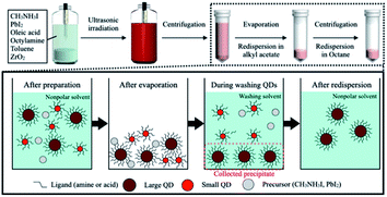 | ||
| Fig. 1 A schema tic illustration of the synthesis and purification processes for obtaining MAPbI3 QDs. | ||
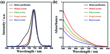 | ||
| Fig. 2 (a) PL spectra and (b) absorption spectra of MAPbI3 QDs before purification and MAPbI3 QDs purified using methyl, ethyl, propyl, and butyl acetate. | ||
To investigate the MAPbI3 QD crystallinity and morphology, XRD patterns and TEM images were obtained (Fig. 3 and 4). From the XRD patterns, all the MAPbI3 QDs showed the following diffraction peaks: 13.9° (110); 28.4° (220); 31.6° (114); 40.4° (321); and 42.9° (402), which were attributed to perovskite crystal structure.18,27,28 Focusing on the XRD pattern of the MAPbI3 QDs before purification, diffraction peaks at 12.6°, 25.9°, and 39.5° were also observed, which were attributed to the perovskite precursor PbI2. These results clearly indicated that unreacted PbI2 was removed from the prepared MAPbI3 QD dispersion through this purification process. Diffraction peaks attributed to ZrO2 beads and MAI, which is another perovskite precursor, were not seen (Fig. ES4†). The TEM images of the MAPbI3 QDs before purification confirmed that there are two types of particles: cubic-shaped particles of about 10 nm and dot-shaped ones of less than 5 nm. On the other hand, the dot-shaped particles disappeared in all the MAPbI3 QD samples after purification. Moreover, the average MAPbI3 QD particle size before purification is 7.2 nm; however, after purification using methyl, ethyl, propyl, and butyl acetate, the average sizes are 11.3 nm, 11.1 nm, 11.0 nm, and 11.2 nm, respectively, showing an increase in the average particle size (Fig. ES5†). This indicates that the purification of MAPbI3 QDs was critical for removing the small particles. The time-resolved PL decay curves of the prepared MAPbI3 QDs are shown in Fig. 5. The average PL lifetime was determined before purification to be 32.0 ns, while after purification, the lifetimes were 46.3 ns (methyl acetate), 41.8 ns (ethyl acetate), 45.6 ns (propyl acetate), and 46.1 ns (butyl acetate), showing a drastic improvement. According to previous reports,18,29 the lifetime of MAPbI3 QDs is related to the particle size, and the PL lifetime can be determined based on this. Therefore, it is possible to easily predict that the increase in the PL lifetime was related to the removal of the small-sized particles. In addition, the PLQY was slightly improved when comparing QDs before and after purification. This suggests that the number of non-luminescent sites, which are short-lived components, decreased, resulting in an increase in the PL lifetime.30,31 From the above results, the unreacted precursors and small MAPbI3 QDs causing PL emission with a wide FWHM were successfully removed and, notably, it was clearly proved that the best purifying solvent is methyl acetate.
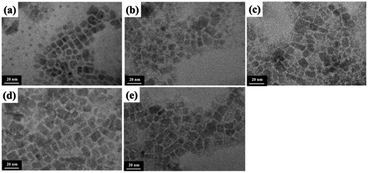 | ||
| Fig. 3 TEM images of MAPbI3 QDs (a) before purification and after purification with (b) methyl acetate, (c) ethyl acetate, (d) propyl acetate, and (e) butyl acetate. | ||
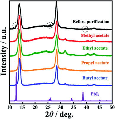 | ||
| Fig. 4 XRD patterns of MAPbI3 QDs before purification, MAPbI3 QDs purified using methyl, ethyl, propyl, and butyl acetate, and the precursor PbI2. | ||
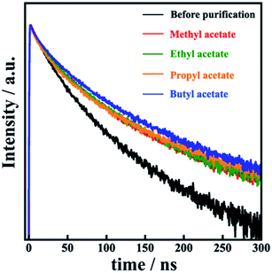 | ||
| Fig. 5 Time-resolved PL decay curves of colloidal MAPbI3 QDs before purification and MAPbI3 QDs purified using methyl, ethyl, propyl, and butyl acetate. | ||
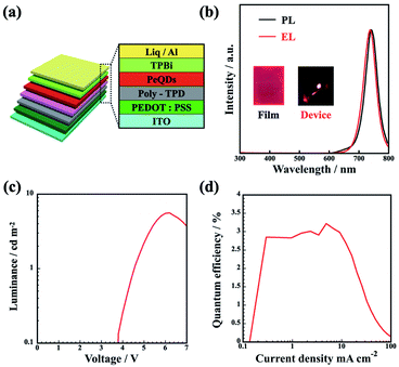
Finally, in order to confirm the effectiveness of the purification process for LED applications, we demonstrated a MAPbI3 QD LED with the following structure: indium tin oxide (ITO)/poly(3,4-ethylenedioxythiophene):poly(styrenesulfonate) (PEDOT:PSS; 40 nm)/poly(4-butylphenyl-diphenyl-amine) (poly-TPD; 20 nm)/MAPbI3 QDs (10 nm)/tris-(1-phenyl-1H-benzimidazole) (TPBi; 50 nm)/lithium 8-quinolate (Liq; 1 nm)/Al (100 nm), as shown in Fig. 6a. Before evaluating the LED device characteristics, the optical properties of the MAPbI3 QD thin film were clarified. The prepared MAPbI3 QD thin film shows a lower PLQY of 48% than the dispersion sample, which indicates the denser packing of MAPbI3 QDs on the substrate causing energy transfer to non-radiative recombination sites.32,33 Fig. 6b shows the PL spectrum of purified MAPbI3 QD thin film prepared via a spin-coating method and the EL spectra of the LED device with MAPbI3 QDs as an emission layer. As seen in Fig. 6b, the EL spectrum of the fabricated LED has an EL peak at 738 nm and a FWHM of 49 nm, which is almost the same as the PL emission spectrum during photoexcitation (a PL peak at 741 nm and a FWHM of 48 nm). In addition, there are no differences in the EL spectrum shape at different current values (Fig. ES6a†). As shown in Fig. 6c, the turn-on voltage is 3.8 V (at 0.1 cd m−2) and the maximum luminance is 5.6 cd m−2 at 6.2 V. The maximum EQE of the prepared LED is 3.2%, as shown in Fig. 6d; as far as we know, the EQE of these MAPbI3 QDs is a new record value.5,34,35 As a result, it can be seen that the suggested MAPbI3 QD purification process utilizing the UBM method has a significant effect on the optical properties and LED device characteristics.
4. Conclusions
In summary, MAPbI3 QDs with good optical properties, e.g., a PLQY of over 60%, were successfully prepared via an UBM method, purifying the QDs using methyl acetate. This is because unreacted perovskite precursors and unsuitably sized MAPbI3 QDs were removed, and the FWHM of PL emission became narrower as a result. The dielectric constant of the carboxylic acid ester used as a purifying solvent affected the absorbance (collected amount) of MAPbI3 QDs, and a linear relationship was confirmed. This was caused by interactions between the alkyl ligands capping the MAPbI3 QD surface and the carboxylic acid ester, especially after a decrease in the hydrophobicity of the carboxylic acid ester. In addition, the MAPbI3 QD thin film based on MAPbI3 QDs purified using methyl acetate showed a PLQY of 48%. A fabricated LED showed brightly luminescent EL at 738 nm with a FWHM of 49 nm, luminance of 5.6 cd m−2, and maximum EQE of 3.2%, which, as far as we know, is a new record EQE for MAPbI3 QDs. Interestingly, the preparation of MAPbI3 QDs via UBM and the purification process can all be performed under air, without needing a glove box. These results indicate that the process is a simple and practical approach for optoelectronic device applications.Conflicts of interest
There are no conflicts to declare.Acknowledgements
This research was supported by Network Joint Research Center for Materials and Devices (20211084), Iketani Science and Technology Foundation (2020), and The Society of Iodine Science (2020).Notes and references
- Q. V. Le, K. Hong, H. W. Jang and S. Y. Kim, Adv. Electron. Mater., 2018, 4, 1800335 CrossRef
.
- P. Lu, M. Lu, H. Wang, N. Sui, Z. Shi, W. W. Yu and Y. Zhang, InfoMat, 2019, 1, 430–459 CrossRef CAS
.
- J. Shamsi, A. S. Urban, M. Imran, L. De Trizio and L. Manna, Chem. Rev., 2019, 119, 3296–3348 CrossRef CAS PubMed
.
- C. Zhang, D. B. Kuang and W. Q. Wu, Small Methods, 2019, 4, 1900662 CrossRef
.
- K. Ji, M. Anaya, A. Abfalterer and S. D. Stranks, Adv. Opt. Mater., 2021, 9, 2002128 CrossRef CAS
.
- S. Paul and A. Samanta, ACS Energy Lett., 2019, 5, 64–69 CrossRef
.
- F. Krieg, S. T. Ochsenbein, S. Yakunin, S. Ten Brinck, P. Aellen, A. Suess, B. Clerc, D. Guggisberg, O. Nazarenko, Y. Shynkarenko, S. Kumar, C. J. Shih, I. Infante and M. V. Kovalenko, ACS Energy Lett., 2018, 3, 641–646 CrossRef CAS PubMed
.
- Y. Tezuka, K. Umemoto, M. Takeda, Y. Takahashi, H. Ebe, J. Enomoto, S. Rodbuntum, T. Nohara, D. Fontecha, S. Asakura, T. Chiba, M. I. Furis, T. Yoshida, H. Uji-i and A. Masuhara, Jpn. J. Appl. Phys., 2020, 59, SDDC04 CrossRef CAS
.
- A. M. A. Leguy, Y. Hu, M. Campoy-Quiles, M. I. Alonso, O. J. Weber, P. Azarhoosh, M. van Schilfgaarde, M. T. Weller, T. Bein, J. Nelson, P. Docampo and P. R. F. Barnes, Chem. Mater., 2015, 27, 3397–3407 CrossRef CAS
.
- R. J. Sutton, G. E. Eperon, L. Miranda, E. S. Parrott, B. A. Kamino, J. B. Patel, M. T. Hörantner, M. B. Johnston, A. A. Haghighirad, D. T. Moore and H. J. Snaith, Adv. Energy Mater., 2016, 6, 1502458 CrossRef
.
- H. Zhao, S. Wang, M. Sun, F. Zhang, X. Li and Y. Xiao, J. Mater. Chem. A, 2018, 6, 10825–10834 RSC
.
- F. Chun, B. Zhang, Y. Li, W. Li, M. Xie, X. Peng, C. Yan, Z. Chen, H. Zhang and W. Yang, Chem. Eng. J., 2020, 399, 125715 CrossRef CAS
.
- L. Protesescu, S. Yakunin, M. I. Bodnarchuk, F. Krieg, R. Caputo, C. H. Hendon, R. X. Yang, A. Walsh and M. V. Kovalenko, Nano Lett., 2015, 15, 3692–3696 CrossRef CAS PubMed
.
- A. Pan, B. He, X. Fan, Z. Liu, J. J. Urban, A. P. Alivisatos, L. He and Y. Liu, ACS Nano, 2016, 10, 7943–7954 CrossRef CAS PubMed
.
- F. Zhang, H. Zhong, C. Chen, X.-g. Wu, X. Hu, H. Huang, J. Han, B. Zou and Y. Dong, ACS Nano, 2015, 9, 4533–4542 CrossRef CAS PubMed
.
- Y. Tang, N. Yan, Z. Wang, H. Yuan, Y. Xin and H. Yin, J. Alloys Compd., 2019, 773, 227–233 CrossRef CAS
.
- L. Ma, D. Guo, M. Li, C. Wang, Z. Zhou, X. Zhao, F. Zhang, Z. Ao and Z. Nie, Chem. Mater., 2019, 31, 8515–8522 CrossRef CAS
.
- F. Zhang, S. Huang, P. Wang, X. Chen, S. Zhao, Y. Dong and H. Zhong, Chem. Mater., 2017, 29, 3793–3799 CrossRef CAS
.
- L. Protesescu, S. Yakunin, O. Nazarenko, D. N. Dirin and M. V. Kovalenko, ACS Appl. Nano Mater., 2018, 1, 1300–1308 CrossRef CAS PubMed
.
- S. Yun, A. Kirakosyan, S.-G. Yoon and J. Choi, ACS Sustainable Chem. Eng., 2018, 6, 3733–3738 CrossRef CAS
.
- M.-G. Jeon, S. Yun, A. Kirakosyan, M. R. Sihn, S.-G. Yoon and J. Choi, ACS Sustainable Chem. Eng., 2019, 7, 19369–19374 CrossRef CAS
.
- K. Umemoto, H. Ebe, R. Sato, J. Enomoto, N. Oshita, T. Kimura, T. Inose, T. Nakamura, T. Chiba, S. Asakura, H. Uji-i and A. Masuhara, ACS Sustainable Chem. Eng., 2020, 8, 16469–16476 CrossRef CAS
.
- J. Li, L. Xu, T. Wang, J. Song, J. Chen, J. Xue, Y. Dong, B. Cai, Q. Shan, B. Han and H. Zeng, Adv. Mater., 2017, 29, 1603885 CrossRef PubMed
.
- K. Hoshi, T. Chiba, J. Sato, Y. Hayashi, Y. Takahashi, H. Ebe, S. Ohisa and J. Kido, ACS Appl. Mater. Interfaces, 2018, 10, 24607–24612 CrossRef CAS PubMed
.
- S. Zhou, RSC Adv., 2021, 11, 28410–28419 RSC
.
- M. Anaya, A. Rubino, T. C. Rojas, J. F. Galisteo-López, M. E. Calvo and H. Míguez, Adv. Opt. Mater., 2017, 5, 1601087 CrossRef
.
- C. C. Stoumpos, C. D. Malliakas and M. G. Kanatzidis, Inorg. Chem., 2013, 52, 9019–9038 CrossRef CAS PubMed
.
- O. Vybornyi, S. Yakunin and M. V. Kovalenko, Nanoscale, 2016, 8, 6278–6283 RSC
.
- S. B. Naghadeh, B. Luo, Y.-C. Pu, Z. Schwartz, W. R. Hollingsworth, S. A. Lindley, A. S. Brewer, A. L. Ayzner and J. Z. Zhang, J. Phys. Chem. C, 2019, 123, 4610–4619 CrossRef CAS
.
- C. Sun, Z. Gao, H. Liu, L. Wang, Y. Deng, P. Li, H. Li, Z.-H. Zhang, C. Fan and W. Bi, Chem. Mater., 2019, 31, 5116–5123 CrossRef CAS
.
- J. Butkus, P. Vashishtha, K. Chen, J. K. Gallaher, S. K. K. Prasad, D. Z. Metin, G. Laufersky, N. Gaston, J. E. Halpert and J. M. Hodgkiss, Chem. Mater., 2017, 29, 3644–3652 CrossRef CAS
.
- T. Chiba, Y. Hayashi, H. Ebe, K. Hoshi, J. Sato, S. Sato, Y.-J. Pu, S. Ohisa and J. Kido, Nat. Photonics, 2018, 12, 681–687 CrossRef CAS
.
- L.-P. Cheng, J.-S. Huang, Y. Shen, G.-P. Li, X.-K. Liu, W. Li, Y.-H. Wang, Y.-Q. Li, Y. Jiang, F. Gao, C.-S. Lee and J.-X. Tang, Adv. Opt. Mater., 2019, 7, 1801534 CrossRef
.
- Y. Hassan, O. J. Ashton, J. H. Park, G. Li, N. Sakai, B. Wenger, A. A. Haghighirad, N. K. Noel, M. H. Song, B. R. Lee, R. H. Friend and H. J. Snaith, J. Am. Chem. Soc., 2019, 141, 1269–1279 CrossRef CAS PubMed
.
- P. Vashishtha, S. Bishnoi, C. H. A. Li, M. Jagadeeswararao, T. J. N. Hooper, N. Lohia, S. B. Shivarudraiah, M. S. Ansari, S. N. Sharma and J. E. Halpert, ACS Appl. Electron. Mater., 2020, 2, 3470–3490 CrossRef CAS
.
Footnote |
| † Electronic supplementary information (ESI) available. See DOI: 10.1039/d1ra08887d |
| This journal is © The Royal Society of Chemistry 2022 |


