
 Open Access Article
 This Open Access Article is licensed under a
 Creative Commons Attribution 3.0 Unported Licence
Corrosion protection performance of silicon-based coatings on carbon steel in NaCl solution: a theoretical and experimental assessment of the effect of plasma-enhanced chemical vapor deposition pretreatment†
Amel Delimiab,
Hana Ferkous ab,
Manawwer Alamc,
Souad Djellalid,
Amel Sedikef,
Kahlouche Abdesalemg,
Chérifa Boulechfarab,
Amina Belakhdarh,
Krishna Kumar Yadavi,
Marina M. S. Cabral-Pintoj,
Byong-Hun Jeon*k and
Yacine Benguerba*l
ab,
Manawwer Alamc,
Souad Djellalid,
Amel Sedikef,
Kahlouche Abdesalemg,
Chérifa Boulechfarab,
Amina Belakhdarh,
Krishna Kumar Yadavi,
Marina M. S. Cabral-Pintoj,
Byong-Hun Jeon*k and
Yacine Benguerba*l
aLaboratoire de Génie mécanique et Matériaux, Faculté de Technologie, Université de 20 août 1955 de Skikda, Skikda 21000, Algeria
bDépartement de Technologie, Université de 20 août 1955 de Skikda, Skikda 21000, Algeria
cDepartment of Chemistry, College of Science, King Saud University, P.O. Box 2455, Riyadh, 11451, Saudi Arabia
dLaboratoire de Physico-Chimie des Hauts Polymères (LPCHP), Faculty of Technology, University Ferhat Abbas Setif1, 19000, Setif, Algeria
eScientific and Technical Research Center in Physico-chemical Analysis, BP 384, Bou-Ismail industrial zone, RP 42004, Tipaza, Algeria
fNanomaterials, corrosion and surface treatment laboratory (LNMCT), BP 12, Badji Mokhtar University, 23000 Annaba, Algeria
gCRTI Research Centre in Industrial Technologies – CRTI, P.O. Box 64, Cheraga 16014, Algiers, Algeria
hLaboratoireMatériaux et SystèmesElectroniques, Universityof BordjBouArreridj, 34000, Algeria
iFaculty of Science and Technology, Madhyanchal Professional University, Ratibad, Bhopal 462044, India
jGeobiotec Research Centre, Department of Geoscience, University of Aveiro, 3810-193, Aveiro, Portugal
kDepartment of Earth Resources and Environmental Engineering, Hanyang University, Seoul 04763, Republic of Korea. E-mail: bhjeon@hanyang.ac.kr
lDepartment of Process Engineering, Faculty of technology, Ferhat Abbas Setif1 University, Setif, Algeria. E-mail: yacinebenguerba@univ-setif.dz
First published on 25th May 2022
Abstract
Using a plasma-assisted chemical vapor deposition (PACVD) process, carbon steel samples were coated with an organosilicon layer less than 2.5 microns thick. Ellipsometry, Fourier transform infrared (FTIR) spectroscopy, contact angle, scanning electron microscopy (SEM), and atomic force microscopy (AFM) were used to analyze the films. Additionally, gravimetric experiments were used to determine the electrochemical properties of the organosilicon coatings. Organosilicon-coated carbon steel specimens demonstrated significantly enhanced resistance to corrosive conditions, such as 3% aqueous sodium chloride solutions. The surface preparation method has a considerable influence on the morphological and electrochemical properties of the steel. Argon pretreatment significantly enhances the corrosion resistance of organosilicon-coated steel. Gravimetric research demonstrated that pretreatment with argon plasma resulted in less weight loss and corrosion than pretreatment with nitrogen plasma. The link between quantum computing and experimental data using density functional theory (DFT) and molecular dynamics (MD) was used.
1. Introduction
Metals that rust can't be utilized in key sectors like aircraft and transportation because of the natural process known as corrosion. Corrosion is a common problem for metallic alloys in industrial applications because of the conditions in which they are used. Applying a protective coating or paint is highly recommended as the most cost-effective and practical strategy to prevent corrosion. Even though coatings and paints are relatively thin, they may be quickly applied over broad areas and provide protection. In most cases, the cost of materials and labor is less than the value of what is being protected. Corrosion-resistant coating and paint technology have advanced consistently over the past 150 years, resulting in a diverse spectrum of solutions for preserving a variety of substrates in a variety of situations. The coatings industry, a mature field, is continually developing novel substrates and application procedures to meet new needs. Coating technology has advanced dramatically during the previous three decades to respond to environmental concerns. As a result, new coating systems and application procedures are being developed.Organic coatings and anticorrosive paint mixes are a common means of preventing corrosion on metal surfaces. The hydrophobic nature can be studied with a dynamic contact angle. This quantitative method shows the increase in hydrophobicity and the decrease in the wettability when organic coatings include fluorinated groups.5 Corrosion mitigation techniques include covering metals with protective coatings that prevent corrosion ions and molecules from accessing their surfaces.
Numerous organic coatings may be modified to improve their surface and bulk properties. Numerous modern coatings are formulated to produce hydrophobic/superhydrophobic surfaces, reliable substrate/coatings interface adhesion, and long-term corrosion protection.1
Amorphous films such as hydrogenated silicon carbide (a-SiCx![[thin space (1/6-em)]](https://www.rsc.org/images/entities/char_2009.gif) :H), silicon nitride (a-SiNx:H), and silicon carbonitride (a-SiCxNy:H) were used as protective coatings on stainless steel.1–3 Corrosion tests performed in 1% sodium chloride solution revealed that the coated samples possessed substantially better corrosion resistance than the bare substrate.
:H), silicon nitride (a-SiNx:H), and silicon carbonitride (a-SiCxNy:H) were used as protective coatings on stainless steel.1–3 Corrosion tests performed in 1% sodium chloride solution revealed that the coated samples possessed substantially better corrosion resistance than the bare substrate.
Chromate conversion coatings have gained popularity due to their application ease.2 These procedures have significant environmental consequences because of the need for potentially hazardous reactants and the generation of toxic waste. As a result, other technologies have been examined. PACVD (plasma-assisted chemical vapor deposition) is used in various sectors, including semiconductor production.3,4 Different organosilicon (ORGS) precursors may be used to fabricate thin films with regulated physicochemical properties. The features of the growing film may be precisely controlled by modifying parameters such as gas flow rates, gas ratios, and even the kind of plasma employed.5 Plasma Assisted Chemical Vapor Deposition (PACVD) is a technique of choice for developing amorphous materials.4 This character is generally associated with a low electrical conductivity of the layers, which avoids any galvanic coupling with the metal substrate, which is thus protected. This technique results in adherent and dense films with a relatively high deposition rate (μm h−1).
The substrate may be prepared immediately before beginning the coating process to improve adhesion further. The researchers believe this, along with the process's low impact on the environment, makes it a viable option for improving metal corrosion resistance. PACVD-grown amorphous ORGS films exhibit a high electrical resistivity (109 to 1015 cm), characteristic of amorphous ORGS films.6,7 In other words, the conditions surrounding the formation of deposits may significantly impact their quality. To boost the barrier properties for corrosion applications, the number of Si–O bonds must be increased, and the hydrogen concentration in the coating decreased.8
Corrosion inhibition was investigated using ORGS coatings, which improved the material's corrosion protection properties and can be synthesized using a straightforward PACVD process.
Furthermore, Density Functional Theory (DFT) is an effective technique for analyzing the corrosion inhibition of many ORGS, with findings correlating with actual data.9 Additionally, DFT simulations were used to deduce the mechanism of ORGS adsorption on the carbon steel surface. This study focuses on the corrosion behavior of carbon steel that has been insulated and prevented from rusting by thin ORGS coatings. After 100 hours of immersion in a solution containing 3% sodium chloride, the corrosion resistance of the interface materials was determined.
2. Materials and methods
2.1. Materials
Arcelor in France provided the carbon steel substrates, which contain 0.37% C, 0.23% Si, 0.68% Mn, 0.5% Cr, 0.16% Cu, 0.059% Ni, 0.016% S, 0.011% Ti and 97.9% Fe. The NaCl was provided by Aldrich.2.2. Surface coating
The following settings were used before the deposit: (i) Ar Pre-treatment: flow rate = 500 SCCM, time = 5 min; N2 pre-treatment: flow rate = 2500 SCCM, time = 5 min.
2.3. Surface characterization
2.4. Theoretical study
From the ionization (I) and electron affinity (A) ground states, it can deduce the hardness (η) and chemical potential (μ) or electronegativity (χ) equations, respectively.
 | (1) |
 | (2) |
| I = −EHOMO | (3) |
| A = −ELUMO | (4) |
EHOMO and ELUMO represent the energy of HOMO and LUMO orbitals, respectively.
The electronegativity and hardness values determine an ion, atom, or molecule's electrophilicity index (ω).14
 | (5) |
The percentage of electrons transported from the ORGS molecule to the carbon steel sample's surface is computed as follows:14
| ΔN = (χFe − χORGS)/2(ηORGS + ηFe) | (6) |
V(r) and G(r), the capacity to aggregate electrons and dilute them via electronic mobility, are in rivalry.17 As a consequence, H(r) = V(r) + G(r) may have a negative or positive total energy density.
Furthermore, positive, ∇2ρ(r) and H values indicate electrostatic contact, while negative values suggest a covalent bond. A partly covalent bond18 is defined as a positive ∇2ρ(r) and a negative H value. The categorization of interactions is therefore based on the values of that indicator, according to these many possibilities: (I) pure shell interaction, |V|/G < 1; (II) shell interaction, 1 < |V|/G < 2; (III) layer sharing interaction, |V|/G > 2. The first two forms of interactions are based on hydrogen bonds, whereas the third type is covalent bonds.
ADF software19,20 was used to calculate AIM. For molecular structure optimization, the DFT-B3LYP was utilized using the def-TZVP basis set.20,21
3. Results and discussion
3.1. ORGS film preparation and characterization
The deposition duration determined the deposited layer's thickness, which was 20 minutes. Profilometric data were used to determine the ORGS layer's thickness, which came out to 2.5 ± 0.1 μm. The interfaces were treated with nitrogen and argon plasmas before the coating was deposited. The final wetting parameters of the coated sample were significantly influenced by the kind of carbon steel surface pretreatment. The static contact angle of polished uncoated carbon steel is 89 ± 2°. With and without any specific preparation or nitrogen plasma treatment, a 2.5-micron thick organosilicon layer significantly increased the water contact angle to 95 ± 2° and 98 ± 2°. However, when pretreated with argon, hydrophobic water contact angles were determined to be 117 ± 2°. This result indicates that the argon-treated film minimizes the contact area between the solution and the solid surface of the metal, thus reducing corrosion.
The wetting parameters of the argon-pretreated contact are very stable throughout time. Indeed, after 20 days, no change in the wetting properties was observed.
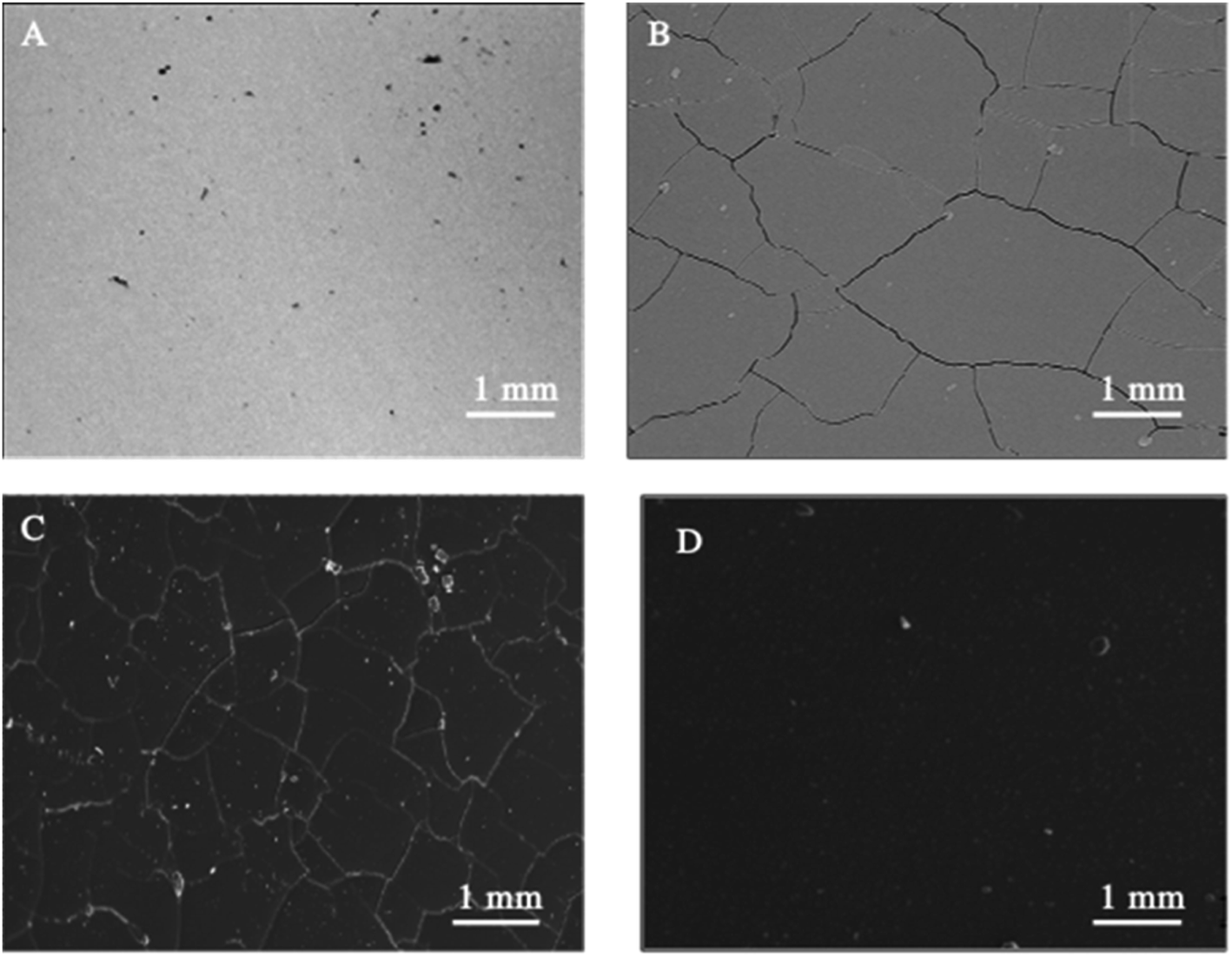
SEM (Fig. 1) and electron microprobe (Fig. 2) investigations examined the interface morphology. The argon pretreatment of carbon steel surfaces before the deposit of the ORGS layer results in an ultra-thin polymer coating with refined grains as contrasted to carbon steel surfaces that have not had nitrogen pretreated or have not been treated at all. The findings of the SEM may be verified using images of back-scattered electrons taken with an electron microprobe. Argon pretreatment results in a smooth surface with minimal defects, while untreated and nitrogen plasma pretreated samples show fractures due to the lack of treatment. Corrosion-resistant coatings may be less effective if exposed to moisture. Although imperfections like holes and cracks make it easier for solutions to penetrate, the carbon steel surface underneath is targeted.
 | ||
| Fig. 1 Surface microstructure of XC38 with various surface pretreatments coated with ORGS: (A) XC38 polished, (B) no pretreat. (C) N2 pretreat. (D) Ar pretreat. | ||
 | ||
| Fig. 2 Microprobe characterization of XC38 with various pretreats coated with ORGS: (A) XC38 polished. (B) no pretreat. (C) N2 pretreat. (D) Ar pretreat. | ||
3.2. Raman characterization
Spectroscopic data has been gathered using Raman spectroscopy (Fig. 3). Because of the deposit's pseudo amorphous structure, the band at 183 cm−1 is ascribed to the crystal lattice mode, while the 486 and 701 cm−1 bands are attributed to the semiconductor Si–O–Si.22–24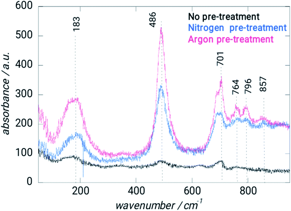 | ||
| Fig. 3 Raman spectrum of XC38 steel without and with different treatments. | ||
Between 750 and 860 cm−1, the CH deformation modes may be detected. EDS analysis verified the coating's amorphous nature (Table 1). Pretreatment with argon results in a bit of reduction in the Si/C ratio, but the Si/O composition remains mostly constant. The Ar–Ar plasma treatment of ORGS resulted in a smooth and homogenous surface. Because of the enhanced energy transfer from the Ar plasma to the ORGS surface, the formerly loose nanostructure has become more compact as the treatment time with Ar plasma has risen, which explains why the carbon content is growing as a percentage.
| Sample | Atomic percentage/% | ||||
|---|---|---|---|---|---|
| Si | O | C | Si/O | Si/C | |
| ORGS coated steel (no pretreatment) | 31.1 | 51.6 | 17.3 | 0.6 | 1.8 |
| ORGS coated steel (N2 pretreatment) | 30.8 | 50.6 | 18.6 | 0.6 | 1.7 |
| ORGS coated steel (Ar pretreatment) | 28.9 | 53.1 | 18.0 | 0.5 | 1.6 |
3.3. Investigation of the corrosion protection efficiently
ORGS coating on carbon steel after many surface treatments has been studied electrochemically and gravimetrically in 3% NaCl aqueous solutions to understand the corrosion prevention mechanism better.
 | (7) |
 | (8) |
For coated and uncoated carbon steel, the gravimetric findings of pretreatment in 3% NaCl with various pretreatments are presented in Table 2: Interfaces that have been pretreated with argon or coated provide superior corrosion resistance. After 30 days of corrosion in 3%, NaCl solutions on argon pretreated samples, protection effectiveness of 81% was found. To evaluate the corrosion behavior of carbon steel interfaces after various pretreatments, coated and uncoated carbon steel interfaces were submerged in a 3% aqueous NaCl solution for up to one month. Silicon-based coatings on carbon steel are believed to help protect metals from corrosion due to their enhanced hydrophobicity, which repels water from the steel/ORGS layer. Additionally, the coating's adhesion stability is intended to be satisfactory in aqueous solutions for an extended time.
| Interface | Duration of submersion (days) | Weight loss (g × 10−3) | υcorr (mpy) | PE (%) |
|---|---|---|---|---|
| Carbon steel | 7 | 3.04 ± 0.03 | 1.51 | 0 |
| 15 | 5.13 ± 0.04 | 1.19 | 0 | |
| 30 | 28.71 ± 0.04 | 3.33 | 0 | |
| Coated steel – no pre-treatment | 7 | 0.95 ± 0.03 | 0.47 | 69 |
| 15 | 2.66 ± 0.03 | 0.61 | 48 | |
| 30 | 19.01 ± 0.03 | 2.20 | 34 | |
| Coated steel – nitrogen pre-treatment | 7 | 0.27 ± 0.03 | 0.18 | 91 |
| 15 | 0.21 ± 0.03 | 0.48 | 59 | |
| 30 | 20.72 ± 0.03 | 2.40 | 28 | |
| Coated steel – argon pre-treatment | 7 | 0.19 ± 0.03 | 0.09 | 99 |
| 15 | 0.38 ± 0.03 | 0.08 | 93 | |
| 30 | 0.55 ± 0.03 | 0.63 | 81 |
Indeed, it is well established that one of the critical factors affecting corrosion stability is the adhesion of metal/ORGS film interfaces, which is influenced by the quantity of water present, the temperature, the build-up of mechanical stress, and the existence of flaws and pores. To determine the efficiency of the ORGS film in protecting carbon steel against corrosion and its adherence to the metal, SEM images were taken after one month of immersion in 3% NaCl aqueous solutions (Fig. 4). In the case of unprotected carbon steel, the production of corrosion products in the form of rust is readily visible in the SEM picture (Fig. 4B). The identical phenomenon was found on a carbon steel surface pretreated with N2. As a result, this ORGS film is unsuitable for protecting the underlying metal contact. In the case of Ar pretreatment, no apparent corrosion products are seen (Fig. 4C), confirming the polymer's firm adherence to the polished steel surface and its corrosion-protective character.
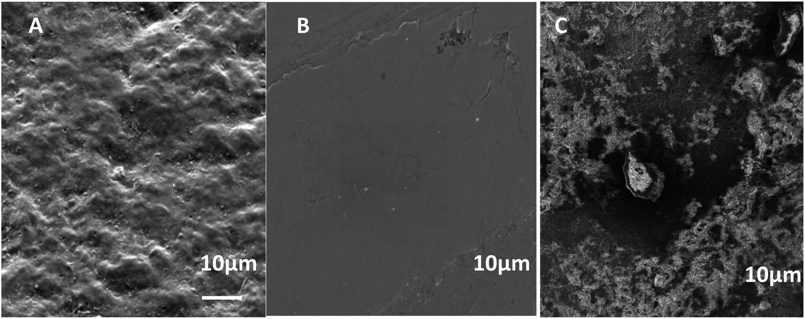 | ||
| Fig. 4 SEM images of (A) XC38 polished, (B) N2 pretreat. (C) Ar pretreat after immersion in a 3% NaCl aqueous solution for one month. | ||
 | ||
| Fig. 5 Time-dependent evolution in a 3% NaCl solution of the abundant potential of (a) XC38 for different surface pretreatments (b) without pretreatment; (c) pretreated with N2; (d) pretreated with Ar. | ||
After roughly 40 hours of immersion in NaCl 3%, a drop in EOCP is seen due to iron dissolution.29 The steel covered with ORGS films had a different behavior from that of the uncoated steel. Because the EOCP was shifted to more positive potential values, the interfaces showed increased corrosion resistance, and there was no noticeable change in EOCP throughout the tests.
 | ||
| Fig. 6 Polarization curves of XC38 for various treatment methods in 3% NaCl of solution during seven days. | ||
Corrosion protection properties of silicon coatings Fig. 5 shows the potentiodynamic polarization curves of uncoated and coated steel with different pretreatment. The corrosion current density (icorr) decreased, and the corrosion potential (Ecorr) increased (positive shift) for steel with argon and nitrogen pretreatment. The coated surface has a protection efficiency of 96% and 93% coated steel – argon pretreatment and coated steel – nitrogen pretreatment, respectively (Table 3). Overall, these results indicate adequate corrosion protection on the surface of the steel and more marks for argon pretreatment in corrosive environments. This coating may be helpful for potential applications that require chemically stable deposits. Eqn (8) can use the corrosion current densities jcorr and j0corr for coated and uncoated steel to determine the corrosion protection (CP) coating.30,31 As with the mass loss studies, the data show that the argon-treated interface has the greatest corrosion resistance.
| Interface | The duration in days of submersion | Ecorr (V) | jcorr (A cm−2) | PE (%) |
|---|---|---|---|---|
| Carbon steel | 7 | −0.88 | 7.2 × 10⁻⁶ | 0 |
| 15 | −0.88 | 3.5 × 10⁻⁵ | 0 | |
| 30 | −0.88 | 1.1 × 10⁻⁴ | 0 | |
| Coated steel – no pre-treatment | 7 | −0.46 | 2.5 × 10⁻⁶ | 65 |
| 15 | −0.46 | 3.6 × 10⁻⁶ | 50 | |
| 30 | −0.48 | 4.7 × 10⁻⁶ | 37 | |
| Coated steel – nitrogen pre-treatment | 7 | −0.58 | 4.5 × 10⁻⁷ | 93 |
| 15 | −0.59 | 2.9 × 10⁻⁶ | 59 | |
| 30 | −0.59 | 5.3 × 10⁻⁶ | 26 | |
| Coated steel – argon pre-treatment | 7 | −0.67 | 2.7 × 10⁻⁷ | 96 |
| 15 | −0.67 | 5.3 × 10⁻⁷ | 92 | |
| 30 | −0.67 | 1.3 × 10⁻⁶ | 82 |
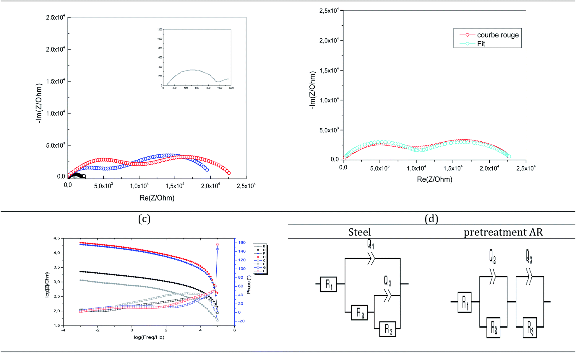 | ||
| Fig. 7 (a) Experimental and (b) fitting EIS (Nyquist) of XC38 (inset, grey) 2.5 μm ORGS coated (black: without pretreatment; blue: pretreated with N2; red: pretreated with Ar), (c) experimental EIS (BODE) and (d) equivalent circuit proposed of XC38 (steel, and pretreated with Ar). | ||
EIS analysis was used to evaluate the corrosion resistance of coatings without affecting the performance of the layer. Thus, EIS analysis was performed on uncoated steel and various pretreated coatings. Nyquist and Bode's plots were collected for these coatings during immersion in a 3.5% NaCl solution (Fig. 7). The Nyquist plot of the carbon steel without coating consisted of one capacitive loop (Fig. 7b). In contrast, the coated samples with different pretreatments indicate two loops generally included the high-frequency semicircular loop, which contained the information about the coating, and the low-frequency semicircular loop had information about the processes related to the reactions of the electrode surface.31 According to the literature, the low-frequency impedance modulus (Z|0.01 Hz) is a suitable parameter to characterize the protective properties of the coating.32 The Bode plot of argon pretreatment (Fig. 7c) showed that the value of |Z|0.01 Hz was 105 Ω cm2. However, it has is of the order of 103 Ω cm2 for untreated steel. This means that the protective property is lower than the coating with argon pretreatment at immersion.
The Nyquist and Bode plots of the coatings with different pretreatments were fitted via the equivalent circuit (Fig. 7d), where R1, R2, R3, Q1, and Q3 are the solution resistance, polarization resistance, constant phase element representing double-layer capacitance, and charge transfer resistance, respectively. The equivalent circuit was used when two capacitive loops appeared in the Nyquist plot. The green line indicates the fitted curves in Fig. 6 and corresponds well to the experimental data. Table 4 shows that the coated carbon steel interfaces have better charge transfer resistance than the uncoated carbon steel interfaces. The untreated coated carbon steel measured 341.8 Ω cm2, while the nitrogen and argon plasma-treated surfaces recorded 9.150 and 9.881 Ω cm2. The charge transfer of a coated steel specimen after immersion in a 3% NaCl solution is shown in Fig. 7.
| Inset | Without pretreatment | Pretreated with N2 | Pretreated with Ar | |
|---|---|---|---|---|
| R1 (Ω) | 47.59 | 115.6 | 22.68 | 103.8 |
| Q2 (F s(a − 1)) | 5.29 × 10⁻⁶ | 1.49 × 10⁻⁶ | 2.51 × 10⁻⁶ | 2.81 × 10⁻⁷ |
| a2 | 0.7836 | 0.6573 | 0.4742 | 0.6427 |
| R2 (Ω) | 341.8 | 1824 | 9150 | 9881 |
| Q3 (F s(a − 1)) | 2.74 × 10⁻⁸ | 0.02635 |
2.36 × 10⁻⁵ | 5.23 × 10⁻⁵ |
| a3 | 0.4882 | 0.5017 | 0.6707 | 0.5267 |
| R3 (Ω) | 580 | 197 | 11180 |
13298 |
| s3 (Ω s−1/2) | 17.38 |
The steel sample exhibited a reduced initial charge transfer resistance, which increased throughout the 100 hour immersion.
3.4. Theoretical study
Frontier molecular orbitals include the highest occupied (HOMO) and lowest unoccupied (LUMO) molecular orbitals. Single-electron excitation of HOMO to LUMO describes the transition from the ground state to the first excited state, known as electronic absorption. As the HOMO–LUMO gap widens, so does the system's kinetic stability. Electron transport from the ground state HOMO to the excited state LUMO needs more energy. Consequently, the HOMO–LUMO gap and other chemical descriptors (e.g., chemical potential (μ), global hardness (η), and electrophilicity index (ω)) are provided in Table 5 for ORGS and Fe18 cluster pure components.| EHOMO (eV) | ELUMO (eV) | GAP (eV) | χ | η | Ω | ΔN | |
|---|---|---|---|---|---|---|---|
| ORGS | −6.401 | 0.128 | 6.529 | 3.137 | 3.265 | 1.507 | 0.251 |
| Fe18 | −3.868 | −3.691 | 0.177 | 3.780 | 0.089 | 80.650 | — |
The ORGS molecule is the most stable because it has the most significant HOMO–LUMO gap and hardness, measuring 6.529 and 3.265 eV (Table 5). Due to its low gap and hardness, the Fe18 cluster was the most reactive material. The donor/acceptor ability could be calculated by calculating the cross-gap values:
| GAP1 = ELUMO(Fe) − EHOMO(ORGS); GAP2 = ELUMO(ORGS) − EHOMO(Fe) | (9) |
GAP1 and GAP2 calculated values were 2.71 and 3.996 eV, respectively. The lowest Gap value shows the possible way of electrons transfer, which means that ORGS is the electron donor (HOMO) and Fe18 is the electron acceptor (LUMO). The higher calculated global electrophilicity index (ω) of Fe18 compared with ORGS confirms the acceptor character of Fe18.
The positive calculated value of ΔN indicates a more remarkable electron-donating ability of the ORGS to the metal surface.
As shown in Fig. 8, the ORGS the HOMO locations are located on the methyl carbons, Si, and O atoms. HOMO or LUMO iron orbitals represent the ability to behave as a donor or an electron acceptor. The ORGS and Fe18 binary interacting system's charge distribution may be seen on the Cosmo surfaces. The complex's non-polar regions are green, the hydrogen bond acceptor (HBA) region is red, and the hydrogen bond donor (HBD) region is blue.
 | ||
| Fig. 8 DFT global reactivity descriptors and COSMO-RS results. | ||
The σ-profiles show that the two molecules are mainly non-polar except low HBA regions characteristic of the oxygen atoms of the ORGS and some iron atoms of the Fe18 cluster. σ-Potentials show that the interaction between ORGS and Fe18 clusters is not possible in the polar region (HBA or HBD) because Fe18 can't make H-bonding (μ(σ) > 0). The only possible interaction could be done in the non-polar region where μ(σ) < 0 of the Fe18 cluster.
Fig. 9 demonstrates that the van der Waals type H(vdW) = −20.40 and −18.07 kcal mol−1 for ORGS and Fe18 is the major contributor to the interaction energy in mixing the two molecules. H(MS) enthalpy electrostatic contributions were found to be less critical. Precisely as was expected, there was no hydrogen bonding (HB). For the ORGS, −17.82 kcal mol−1 was the maximum mixing enthalpy, H(int).
 | ||
| Fig. 9 ORGS@Fe18 interaction energies. | ||
As seen in Fig. 10, the optimized ORGS/Fe18 complex exhibits a molecular graph, and the topological properties of the interaction contacts at the BCP are listed in Table 6.
 | ||
| Fig. 10 ORGS@Fe18 AIM analysis. | ||
| BCP | ρ(r) (Ha) | ∇2ρ(r) (Ha) | G(r) (Ha) | V(r) (Ha) | EHB (eV) | HC (Ha) = G + V | G/|V| |
|---|---|---|---|---|---|---|---|
| 75 | 1.62 × 10⁻² | 2.68 × 10⁻² | 7.46 × 10⁻³ | −8.21 × 10⁻³ | −1.12 × 10⁻¹ | −7.47 × 10⁻⁴ | 9.09 × 10⁻¹ |
| 95 | 1.35 × 10⁻¹ | 8.36 × 10⁻¹ | 2.42 × 10⁻¹ | −2.74 × −1 | −3.73 | −3.27 × 10⁻² | 8.81 × 10⁻¹ |
| 111 | 1.79 × 10⁻² | 1.56 × 10⁻¹ | 2.95 × 10⁻² | −2.01 × 10⁻² | −2.73 × 10⁻¹ | 9.48 × 10⁻³ | 1.47 |
| 118 | 2.44 × 10⁻² | 1.66 × 10⁻¹ | 3.36 × 10⁻² | −2.56 × 10⁻² | −3.49 × 10⁻¹ | 7.98 × 10⁻³ | 1.31 |
| 168 | 1.59 × 10⁻¹ | 4.61 × 10⁻¹ | 2.11 × 10⁻¹ | −3.08 × 10⁻¹ | −4.19 | −9.62 × 10⁻² | 6.87 × 10⁻¹ |
| 173 | 7.27 × 10⁻² | 6.92 × 10⁻¹ | 1.52 × 10⁻¹ | −1.30 × 10⁻¹ | −1.77 | 2.13 × 10⁻² | 1.16 |
In BCPs, the ρ(r) values range from [0.0162, 0.159] Ha and ∇2ρ(r) is positive, indicating the existence of Hydrogen bonds interaction in the case of O⋯Fe and H⋯Fe, respectively (see Fig. 9). A summary of the findings may be found in the ESI.†
For BCPs 111, 118, and 173, positive ∇2ρ(r) and HC values imply a weak molecular bonding (electrostatic interaction) between the atoms of the compounds (see Fig. 9). In this case G/|V| > 1, the ability to group electrons, V(r) is less than the ability to dilute them, G(r). EHB < 0 characterizes the poor hydrogen bonding.33 The bonds O (25)⋯Fe (17), H (48)⋯Fe (11) and O (23)⋯Fe (16) are all determined to be of a physical character (no covalent bonding). At the BCPs 75, 95, and 168, the negative HC and positive ∇2ρ(r) values in the case of H (43)⋯Fe (10), 0 (27)⋯Fe (18) and H (49)⋯Fe (10) demonstrates the partially covalent character. This result is corroborated by the fact that the ability to group electrons, V(r), is stronger than the ability to dilute them through electronic mobility, G(r) where  .
.
4. Conclusion
The present study demonstrates the successful deposition of thin SiOx-like coatings onto carbon steel using plasma-assisted chemical vapor deposition. The concept is straightforward to apply to massive surfaces. The created architecture was hydrophobic and adhered to the underlying steel contact. A 2.5 μm thick argon pretreatment coating demonstrated exceptional adhesion stability and hydrophobicity (water contact angle of 117 ± 2°). In a 3% NaCl aqueous solution, the inhibition efficacy of the silica films against corrosion was determined. While shallow SiOx-like coating layers (2.5 μm) without pretreatment do not protect carbon steel surfaces from corrosion, larger silica layers with argon pretreatment do. Indeed, polarization investigations on an argon pretreatment steel surface revealed a protection efficiency of 96%. This is somewhat less than the 99% protection efficiency observed by Pech et al.8 and Delimi et al.34 on steel samples covered by a 600 nm thick silica-based coating.3,34 However, the findings indicate that three times thinner amorphous silica films already possess a significant level of protection. Thus, thin SiOx-like layers constitute an intriguing possibility for easily and affordably increasing the anticorrosion performance of diverse materials. The coatings adhered effectively to the carbon-steel surface according to the theoretical study. The van der Waals forces were revealed to account for the bulk of the interaction energy. Electrostatic forces were discovered to have a lesser effect.Author contributions
Amel Delimi, Hana Ferkous: experimental investigation, discussion of results, draft preparation. Souad Djellali, Amel Seddik, Kahlouche Abdessalem, Chérifa Boulechfar, Amina Belakhdar: discussion of results, draft preparation. Marina M. S. Cabral-Pinto, Manawwer Alam: theoretical investigation, discussion of results. Krishna Kumar Yadav, Byong-Hun Jeon: editing and writing, funding research. Yacine Benguerba: theoretical investigation, discussion of results, editing and writing.Conflicts of interest
There are no conflicts to declare.Acknowledgements
The authors are grateful to the researchers supporting project number (RSP-2021/113), King Saud University, Riyadh, Saudi Arabia, and the Korea Institute of Energy Technology Evaluation and Planning (KETEP) grant by the Ministry of Trade, Industry and Energy (MOTIE) of South Korean Govt. (No. 20206410100040) for the support.References
- U. Eduok, O. Faye and J. Szpunar, Recent developments and applications of protective silicone coatings: A review of PDMS functional materials, Prog. Org. Coat., 2017, 111, 124–163 CrossRef CAS.
- Z. L. Long, Y. C. Zhou and L. Xiao, Characterization of black chromate conversion coating on the electrodeposited zinc-iron alloy, Appl. Surf. Sci., 2003, 218(1), 124–137, DOI:10.1016/S0169-4332(03)00572-5.
- A. Pfuch, A. Heft, R. Weidl and K. Lang, Characterization of SiO2 thin films prepared by plasma-activated chemical vapour deposition, Surf. Coat. Technol., 2006, 201(1), 189–196, DOI:10.1016/j.surfcoat.2005.11.110.
- D. R. Cote, et al., Plasma-assisted chemical vapor deposition of dielectric thin films for ULSI semiconductor circuits, IBM J. Res. Dev., 1999, 43(1.2), 5–38, DOI:10.1147/rd.431.0005.
- H. K. Yasuda, T. F. Wang, D. L. Cho, T. J. Lin and J. A. Antonelli, Corrosion protection of cold-rolled steel by low temperature plasma interface engineering II. Effects of oxides on corrosion performance of E-coated steels, Prog. Org. Coat., 1997, 30(1), 31–38, DOI:10.1016/S0300-9440(96)00651-0.
- Y. Matsumoto, Hot wire-CVD deposited a-SiOx and its characterization, Thin Solid Films, 2006, 501(1), 95–97, DOI:10.1016/j.tsf.2005.07.132.
- C. Régnier, P. Tristant and J. Desmaison, Remote microwave plasma-enhanced chemical vapour deposition of insulating coatings (SiO2) on metallic substrates: film properties, Surf. Coat. Technol., 1996, 80(1), 18–22, DOI:10.1016/0257-8972(95)02679-7.
- D. Pech, P. Steyer, A.-S. Loir, J. C. Sánchez-López and J.-P. Millet, Analysis of the corrosion protective ability of PACVD silica-based coatings deposited on steel, Surf. Coat. Technol., 2006, 201(1), 347–352, DOI:10.1016/j.surfcoat.2005.11.130.
- G. Dakroub, T. Duguet, J. Esvan, C. Lacaze-Dufaure, S. Roualdes and V. Rouessac, Comparative study of bulk and surface compositions of plasma polymerized organosilicon thin films, Surf. Interfaces, 2021, 25, 101256 CrossRef CAS.
- F. Z. Bouanis, F. Bentiss, M. Traisnel and C. Jama, Enhanced corrosion resistance properties of radiofrequency cold plasma nitrided carbon steel: Gravimetric and electrochemical results, Electrochim. Acta, 2009, 54(8), 2371–2378, DOI:10.1016/j.electacta.2008.10.068.
- F. Bentiss, M. Lagrenee, M. Traisnel and J. C. Hornez, Corrosion Inhibition of Mild Steel in 1 M Hydrochloric Acid by 2,5-Bis(2-Aminophenyl)-1,3,4-Oxadiazole, Corrosion, 1999, 55(10), 968–976, DOI:10.5006/1.3283933.
- T. Aissaoui, Y. Benguerba and I. M. AlNashef, Theoretical investigation on the microstructure of triethylene glycol based deep eutectic solvents: COSMO-RS and TURBOMOLE prediction, J. Mol. Struct., 2017, 1141, 451–456, DOI:10.1016/j.molstruc.2017.04.009.
- H. Ferkous, S. Djellali, R. Sahraoui, Y. Benguerba, H. Behloul and A. Çukurovali, Corrosion inhibition of mild steel by 2-(2-methoxybenzylidene) hydrazine-1-carbothioamide in hydrochloric acid solution: Experimental measurements and quantum chemical calculations, J. Mol. Liq., 2020, 307, 112957, DOI:10.1016/j.molliq.2020.112957.
- A. Belakhdar, et al., Computational and experimental studies on the efficiency of Rosmarinus officinalis polyphenols as green corrosion inhibitors for XC48 steel in acidic medium, Colloids Surf., A, 2020, 606, 125458, DOI:10.1016/j.colsurfa.2020.125458.
- K. A. Kurnia, F. Lima, A. F. M. Cláudio, J. A. P. Coutinho and M. G. Freire, Hydrogen-bond acidity of ionic liquids: an extended scale, Phys. Chem. Chem. Phys., 2015, 17(29), 18980–18990, 10.1039/c5cp03094c.
- B. A. Shainyan, N. N. Chipanina, T. N. Aksamentova, L. P. Oznobikhina, G. N. Rosentsveig and I. B. Rosentsveig, Intramolecular hydrogen bonds in the sulfonamide derivatives of oxamide, dithiooxamide, and biuret. FT-IR and DFT study, AIM and NBO analysis, Tetrahedron, 2010, 66(44), 8551–8556, DOI:10.1016/j.tet.2010.08.076.
- S. J. Grabowski and J. M. Ugalde, Bond paths show preferable interactions: Ab initio and QTAIM studies on the X-H⋯π hydrogen bond, J. Phys. Chem. A, 2010, 114(26), 7223–7229, DOI:10.1021/jp103047p.
- I. Rozas, I. Alkorta and J. Elguero, Behavior of ylides containing N, O, and C atoms as hydrogen bond acceptors, J. Am. Chem. Soc., 2000, 122(45), 11154–11161, DOI:10.1021/ja0017864.
- G. te Velde, et al., Chemistry with ADF, J. Comput. Chem., 2001, 22(9), 931–967, DOI:10.1002/jcc.1056.
- W. Bououden, et al., Surface Adsorption of Crizotinib on Carbon and Boron Nitride Nanotubes as Anti-Cancer Drug Carriers: COSMO-RS and DFT Molecular Insights, J. Mol. Liq., 2021, 338, 116666, DOI:10.1016/j.molliq.2021.116666.
- L. Chen, et al., Performance of DFT functionals for properties of small molecules containing beryllium, tungsten and hydrogen, Nucl. Mater. Energy, 2020, 22, 100731, DOI:10.1016/j.nme.2020.100731.
- S. Shoval, M. Boudeulle, S. Yariv, I. Lapides and G. Panczer, Micro-Raman and FT-IR spectroscopy study of the thermal transformations of St. Claire dickite, Opt. Mater., 2001, 16(1), 319–327, DOI:10.1016/S0925-3467(00)00092-6.
- A. Mackova, et al., The combined study of the organosilicon films by RBS, ERDA and AFM analytical methods obtained from PECVD and PACVD, Surf. Sci., 2004, 566–568, 1143–1146, DOI:10.1016/j.susc.2004.06.072.
- B. Champagnon, G. Panczer, C. Chemarin and B. Humbert-Labeaumaz, Raman study of quartz amorphization by shock pressure, J. Non-Cryst. Solids, 1996, 196, 221–226, DOI:10.1016/0022-3093(95)00590-0.
- Y. Yan, W. Li, L. Cai and B. Hou, Electrochemical and quantum chemical study of purines as corrosion inhibitors for mild steel in 1M HCl solution, Electrochim. Acta, 2008, 53(20), 5953–5960, DOI:10.1016/j.electacta.2008.03.065.
- F. Bentiss, et al., Corrosion control of mild steel using 3,5-bis(4-methoxyphenyl)-4-amino-1,2,4-triazole in normal hydrochloric acid medium, Corros. Sci., 2009, 51(8), 1628–1635, DOI:10.1016/j.corsci.2009.04.009.
- G. A. Moraga, G. G. Silva, T. Matencio and R. M. Paniago, Poly(2,5-dimethoxy aniline)/fluoropolymer blend coatings to corrosion inhibition on stainless steel, Synth. Met., 2006, 156(16), 1036–1042, DOI:10.1016/j.synthmet.2006.06.026.
- A. Ouerd, C. Alemany-Dumont, B. Normand and S. Szunerits, Reactivity of CoCrMo alloy in physiological medium: Electrochemical characterization of the metal/protein interface, Electrochim. Acta, 2008, 53(13), 4461–4469, DOI:10.1016/j.electacta.2008.01.025.
- E. Akbarinezhad, M. Ebrahimi and H. R. Faridi, Corrosion inhibition of steel in sodium chloride solution by undoped polyaniline epoxy blend coating, Prog. Org. Coat., 2009, 64(4), 361–364, DOI:10.1016/j.porgcoat.2008.07.018.
- P. E. Hintze and L. M. Calle, Electrochemical properties and corrosion protection of organosilane self-assembled monolayers on aluminum 2024-T3, Electrochim. Acta, 2006, 51(8), 1761–1766, DOI:10.1016/j.electacta.2005.02.147.
- D. Zhu and W. J. van Ooij, Corrosion protection of metals by water-based silane mixtures of bis-[trimethoxysilylpropyl]amine and vinyltriacetoxysilane, Prog. Org. Coat., 2004, 49(1), 42–53, DOI:10.1016/j.porgcoat.2003.08.009.
- F. Fracassi, R. d'Agostino, F. Palumbo, E. Angelini, S. Grassini and F. Rosalbino, Application of plasma deposited organosilicon thin films for the corrosion protection of metals, Surf. Coat. Technol., 2003, 174–175, 107–111, DOI:10.1016/S0257-8972(03)00422-5.
- M. Yoosefian, A. Pakpour and N. Etminan, Nanofilter platform based on functionalized carbon nanotubes for adsorption and elimination of Acrolein, a toxicant in cigarette smoke, Appl. Surf. Sci., 2018, 444, 598–603 CrossRef CAS.
- A. Delimi, Y. Coffiniera, B. Talhi, R. Boukherroub and S. Szunerits, Investigation of the corrosion protection of SiOx-like oxide films deposited by plasma-enhanced chemical vapor deposition onto carbon steel, Electrochimica Acta, 2010, 55(28), 8921–8927 CrossRef CAS.
Footnote |
| † Electronic supplementary information (ESI) available. See https://doi.org/10.1039/d1ra08848c |
| This journal is © The Royal Society of Chemistry 2022 |