 Open Access Article
Co,N-co-doped graphene sheet as a sulfur host for high-performance lithium–sulfur batteries
Haili Zhaoa,
Peng Chen *a,
Yu Fana,
Junkai Zhang
 b,
HongSheng Jiab,
Jianxun Zhaoa,
Heng Liua,
Xin Guo
 a,
Xinwei Wanga and
Wanqiang Liu
 *a
*a
aSchool of Materials Science and Engineering, Changchun University of Science and Technology, Changchun 130022, China. E-mail: chenp044@nenu.edu.cn; wqliu1979@126.com
bChina Key Laboratory of Functional Materials Physics and Chemistry of the Ministry of Education, Jilin Normal University, Siping 136000, China
First published on 6th January 2022
Abstract
To improve the performance of lithium-sulfur (Li–S) batteries, herein, based on the idea of designing a material that can adsorb polysulfides and improve the reaction kinetics, a Co,N-co-doped graphene composite (Co–N–G) was prepared. According to the characterization of Co–N–G, there was a homogeneous and dispersed distribution of N and Co active sites embedded in the Co–N–G sample. The 2D sheet-like microstructure and Co, N with a strong binding energy provided significant physical and chemical adsorption functions, which are conducive to the bonding S and suppression of LiPSs. Moreover, the dispersed Co and N as catalysts promoted the reaction kinetics in Li–S batteries via the reutilization of LiPSs and reduced the electrochemical resistance. Thus, the discharge specific capacity in the first cycle for the Co–N–G/S battery reached 1255.7 mA h g−1 at 0.2C. After 100 cycles, it could still reach 803.0 mA h g−1, with a retention rate of about 64%. This phenomenon proves that this type of Co–N–G composite with Co and N catalysts plays an effective role in improving the performance of batteries and can be further studied in Li–S batteries.
1. Introduction
Based on the increasing demands on electricity storage devices, Li–S batteries have received tremendous attention due to their high energy storage ability, offering a theoretical specific capacity of 1675 mA h g−1 and energy density of 2600 W h g−1.1–5 Moreover, Li–S batteries have many advantages, such as low cost, available materials, and environmental friendliness.6–11 However, Li–S batteries still have many problems to be solved urgently. Among them, the main issues that impede the commercialization of Li–S batteries are as follows: (i) sulfur as an active material is and insulator, and thus it cannot effectively transport ions and electrons in the electrode.12,13 (ii) During the reaction, the “shuttle effect” leads to loss of the active material, Li electrode passivation, and serious overcharge in the battery.14–16 (iii) The terrible volume expansion of the active material destroys the structural stability.17–19 Furthermore, all the above-mentioned problems cause a rapid capacity decay, low discharge capacity, and incomplete cathode structure.20,21Many researchers have focused substantial effort to solve the above-mentioned problems, adopting various strategies such as modifying the separator,22,23 exploiting new electrolytes,24,25 protecting the Li anode,26,27 and improving the sulfur hosting.8,28,29 One of the common methods is designing unique nanostructure materials to host sulfur by physical adsorption or/and chemical bonding.30 Graphene has special significance as a sulfur host material because of its atomically thin 2D structure, large specific surface area, good conductivity, catalytic activity, and excellent mechanical properties.31–33 It has been reported that the graphene can be combined with polar metal oxides, metal sulfides, and metal nitrides as active sites to anchor LiPSs by strong chemical bonding.34 The combination of graphene with transition metals effectively solves its problems, such as irreversible agglomeration, non-porous structure, and nonpolar physical barrier, and further enhances its electrochemical properties.35 However, transition metal/graphene compounds still exhibit the following key issues. Firstly, their interaction with the polar polysulfides is very weak. Secondly, their intrinsic low electronic conductivity increases the internal resistance. In addition, their high weight density counteracts the superior energy density of Li–S batteries.
Recently, much effort has been devoted to the development of nano-electrocatalysts with a high surface free energy, which not only can trap LiPSs due to their superior polarity, but also serve as electrocatalytic centers with sufficient exposure and accessibility.36 Moreover, transition metal catalysts on graphene ensure it acts as a conductive and flexible mechanical host for sulfur. Qiu et al. fabricated cobalt-embedded nitrogen-doped hollow carbon nanorods as sulfur hosts.9,37 Li et al. prepared N-doped carbon dodecahedron-supported Co as a sulfur host, exhibiting a good rate performance and recyclability.38 Kong and co-workers reported a cobalt-based catalyst for Li–S batteries with a high content of sulfur, certifying that the electrocatalysis enabled the accelerated formation and decomposition of lithium sulfides during the cycling processes.39 Huang et al. provided a porphyrin-derived atomic catalyst and discussed the dynamics of LiPSs.40 All these researchers have proven that transition metals can effectively promote the kinetics in Li–S batteries, resulting in an enhancement in their electrochemical performance. However, these methods usually involve sophisticated design and complicated processes, further hindering the scalable application of Li–S batteries. In this regard, it is urgent to design and develop simple and universal methods to produce transition metal/graphene composite-supporting electrocatalysts for high-performance Li–S batteries. Moreover, this method can open a new avenue for the doping of other metals in carbon materials.
In this work, we synthesized Co and N-doped graphene (Co–N–G) with well-dispersed Co and N catalysts embedded in graphene, which was used as a multi-functional anchor material for Li–S batteries. The Co, N catalysts were uniformly dispersed in graphene, hindering the crossover of polysulfides due to their strong physisorption–chemisorption. Moreover, the Co and N catalysts have a synergistic facilitation effect for the conversion of LiPSs into soluble short-chain LiPSs, reduction of short-chain LiPSs into Li2S and the oxidation of Li2S to sulfur, promoting the reaction kinetics during the battery charge and discharge process. Consequently, the battery with the Co–N–G cathode displayed the discharge specific capacity in the first cycle of 1255.7 mA h g−1 at 0.2C, concurrently with a satisfactory capacity retention of 64% after 100 cycles. This demonstrates the great potential of atom-scale Co–N–G composites for application in high-energy Li–S batteries.
2. Experimental section
2.1. Synthesis of Co–N–G
100.0 mg RGO was initially suspended in 30.0 mL formamide under sonication for 0.5 h, followed by the addition of 0.087 g Co(NO3)2·6H2O under sonication for another 0.5 h to form a homogeneous solution containing 0.01 mol L−1 Co2+. Then the Co2+/GO/FA suspension was transferred to a Teflon-lined autoclave and heated at 180 °C for 12 h.2.2. Synthesis of Co–N–G/S composites
Sulfur cathode materials were prepared via the melt diffusion method using different proportions of the composite materials as supports. Co–N–G and sublimed sulfur were ground in an agate mortar at a mass ratio of 3![[thin space (1/6-em)]](https://www.rsc.org/images/entities/char_2009.gif) :
:![[thin space (1/6-em)]](https://www.rsc.org/images/entities/char_2009.gif) 7 for 30 min to mix them well. This mixture was placed in an autoclave, and the reactor was tightened in an argon-filled glove box. Then, the reaction kettle was placed in an electric blast drying box, heated to 155 °C at a heating rate of 5 °C min−1 and kept for 12 h. Finally, the Co–N–G/S composite cathode material was obtained.
7 for 30 min to mix them well. This mixture was placed in an autoclave, and the reactor was tightened in an argon-filled glove box. Then, the reaction kettle was placed in an electric blast drying box, heated to 155 °C at a heating rate of 5 °C min−1 and kept for 12 h. Finally, the Co–N–G/S composite cathode material was obtained.
2.3. Material characterizations
We adopted the following testing methods to observe the physical appearance and chemical properties of the different materials. We used an Ultima VI (Rigaku Corporation) type X-ray diffractometer (XRD) to analyze the crystal structure and for the phase identification of the different samples and selected the copper target excitation ray (Cu-Kα, λ = 1.54 Å). The microscopic morphology such as atomic-resolution aberration-corrected high-angle annular dark-field image-scanning transmission electron microscopy (HAADF-STEM), high-resolution TEM (HRTEM) and elemental mappings were detected using a JSM-6701F type transmission electron microscope (TEM). XPS was performed on an ESCALABMKLL (Thermo Fisher Scientific Company). Raman spectroscopy was carried out using a LabRAM HR800 Raman spectrometer at an emission wavelength of 532 nm.2.4. Electrochemical measurements
Electrochemical measurements were performed herein using CR2025 coin cell batteries. The sulfur cathode materials were mixed with acetylene black and polyvinylidene fluoride (PVDF) with a mass ratio of 7![[thin space (1/6-em)]](https://www.rsc.org/images/entities/char_2009.gif) :
:![[thin space (1/6-em)]](https://www.rsc.org/images/entities/char_2009.gif) 2
2![[thin space (1/6-em)]](https://www.rsc.org/images/entities/char_2009.gif) :
:![[thin space (1/6-em)]](https://www.rsc.org/images/entities/char_2009.gif) 1. The mixture was dissolved in N-methyl-2-pyrrolidone (NMP) solvent. The prepared slurry was coated on carbon-coated aluminum foil and kept at 60 °C in a vacuum environment for 12 h for drying treatment. The above-mentioned material was then cut into a disc with a diameter of 12 mm to be used as the cathode in the coin cells. We used Li foil as the counter electrode and reference electrode in the batteries and assembled the CR2025 batteries in a glove box filled with argon. The electrolyte was prepared using 1 M lithium bis(trifluoromethane sulfonyl)imide (LiTFSI) and 0.1 wt% LiNO3 in cosolvents of 1,3-dioxolane and 1,2-dimethoxyethane (v/v = 1
1. The mixture was dissolved in N-methyl-2-pyrrolidone (NMP) solvent. The prepared slurry was coated on carbon-coated aluminum foil and kept at 60 °C in a vacuum environment for 12 h for drying treatment. The above-mentioned material was then cut into a disc with a diameter of 12 mm to be used as the cathode in the coin cells. We used Li foil as the counter electrode and reference electrode in the batteries and assembled the CR2025 batteries in a glove box filled with argon. The electrolyte was prepared using 1 M lithium bis(trifluoromethane sulfonyl)imide (LiTFSI) and 0.1 wt% LiNO3 in cosolvents of 1,3-dioxolane and 1,2-dimethoxyethane (v/v = 1![[thin space (1/6-em)]](https://www.rsc.org/images/entities/char_2009.gif) :
:![[thin space (1/6-em)]](https://www.rsc.org/images/entities/char_2009.gif) 1). Cyclic voltammetry (CV) measurements were performed on an electrochemical station (CS350, Wuhan Corrtest Instrument Corp., Ltd.). Electrochemical impedance spectroscopy (EIS) tests were performed on a CHI660B electrochemical workstation from 105 Hz to 10−2 Hz with an applied amplitude of 5 mV. The rate capacity and cycling stability were tested using a battery testing system (LAND CT2001A) between 1.7 V and 2.8 V (vs. Li/Li+).
1). Cyclic voltammetry (CV) measurements were performed on an electrochemical station (CS350, Wuhan Corrtest Instrument Corp., Ltd.). Electrochemical impedance spectroscopy (EIS) tests were performed on a CHI660B electrochemical workstation from 105 Hz to 10−2 Hz with an applied amplitude of 5 mV. The rate capacity and cycling stability were tested using a battery testing system (LAND CT2001A) between 1.7 V and 2.8 V (vs. Li/Li+).
3. Result and discussion
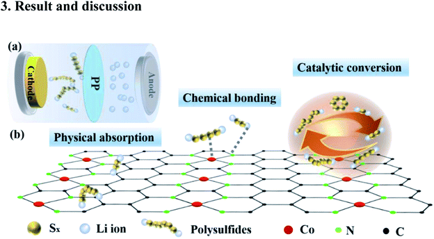
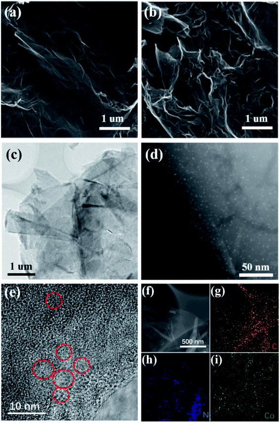
We designed the two-dimensional graphene with dispersed Co–N catalysts as a multifunctional S holding material in Li–S batteries to improve the retention of LiPSs and accelerate the reaction kinetics. As described in Fig. 1, for the first function, the layered multicomponent Co–N–G with a two-dimensional network structure and mechanical strength significantly improves the sulfur bonding and the physical absorption of LiPSs. Moreover, the second function is that the Co and N sites contribute to the binding of LiPSs and Li ions via strong chemical absorption, which can enhance the reutilization of inactivated LiPSs. Specially, the third function is the catalysis by Co and N, which can increase the sulfur utilization by prompting the reversible conversion of LiPSs.We used a modified solvothermal method with AF as an intermediary to synthesize the monodispersed Co catalyst embedded in nitrogen-doped graphene. The morphology and microstructure of Co–N–G were investigated using SEM, TEM and HAADF-STEM. The SEM images of the pristine RGO and the Co–N–G composite are shown in Fig. 2a and b. The Co–N–G composite still maintained a complete layer structure and smooth surface and no large cobalt nanoparticles or big clusters were formed on the sample. In the TEM image in Fig. 2c, the wrinkles on the Co–N–G surface can be seen clearly, proving the well-defined 2D sheet-like microstructure of the Co–N–G composite. The 2D sheet structure is beneficial to significantly improve the sulfur loading and effectively enhance the physical adsorption to trap LiPSs owing to its large specific surface area.41 To directly investigate the morphology of the Co catalyst on graphene, we performed resolution aberration-corrected HAADF-STEM for the Co–N–G sample. The image in Fig. 2d shows numerous individual bright dots randomly dispersed in the 2D nanosheets, suggesting that the Co catalyst did not exhibit obvious serious agglomeration and was embedded on graphene.42 Moreover, in Fig. 2e, there are some red circles marking the aligned lattice fringes in the HRTEM image of Co–N–G, corresponding to the nano Co catalyst. The EDAX mapping images of Co–N–G are shown in Fig. 2f–i, which indicate that there is a homogeneous and dispersive distribution of C, N, and Co elements in the Co–N–G sample.43
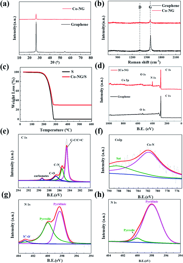
The XRD spectra of Co–N–G and graphene were further analyzed to investigate their crystal structure, where only one diffraction peak at 26.4°, corresponding to the (002) crystal plane, was observed for both Co–N–G and graphene (Fig. 3a).44 This result indicates that no large cobalt-containing clusters could be detected by XRD examination, which is consistent with the result from the HRTEM images. Obviously, with the participation of Co and N, the intensity of the diffraction peak was reduced significantly. This implies that the sp2 ordered arrangement in the carbon catalyst became irregular with the embedding of Co and N.32 According to the analysis of Raman spectroscopy on Co–N–G, there are two characteristic peaks located at 1345 cm−1 for the D peak and 1575 cm−1 for the G peak (Fig. 3b).45 The value of ID/IG is usually used to indicate the disorder degree of the C![[double bond, length as m-dash]](https://www.rsc.org/images/entities/char_e001.gif) C vibration mode. By calculation, the values of the ID/IG ratios of graphene and Co–N–G are 0.17 and 0.52, respectively.46 This proves that the atomic arrangement is more irregular for Co–N–G than graphene, suggesting the doping of Co and N. The sulfur content measured by TGA for the composite was 66.3 wt% (Fig. 3c). It was observed that the vaporization of sulfur started at around 150 °C and was completed at around 300 °C. The composition and the bonding between the catalyst and graphene were investigated by XPS measurement. As shown in Fig. 3d, the elements of C, N, O and Co can be detected in the XPS full spectrum of the Co–N–G sample. In the XPS spectra of C element (Fig. 3e), the peaks at 286.7, 285.5 and 284.8 eV correspond to the C–O, C–N and C–C/C
C vibration mode. By calculation, the values of the ID/IG ratios of graphene and Co–N–G are 0.17 and 0.52, respectively.46 This proves that the atomic arrangement is more irregular for Co–N–G than graphene, suggesting the doping of Co and N. The sulfur content measured by TGA for the composite was 66.3 wt% (Fig. 3c). It was observed that the vaporization of sulfur started at around 150 °C and was completed at around 300 °C. The composition and the bonding between the catalyst and graphene were investigated by XPS measurement. As shown in Fig. 3d, the elements of C, N, O and Co can be detected in the XPS full spectrum of the Co–N–G sample. In the XPS spectra of C element (Fig. 3e), the peaks at 286.7, 285.5 and 284.8 eV correspond to the C–O, C–N and C–C/C![[double bond, length as m-dash]](https://www.rsc.org/images/entities/char_e001.gif) C bonds, indicating the interaction between the introduced heterocatalyst and the carbon matrix.47 The XPS Co2p spectrum in Fig. 3f shows that the Co species are present in the oxidation state of Co2+ at 781.8 eV, confirming the coordination configuration of Co bonding in Co–N.48,49 Three peaks for pyridinic, pyrrolic, and oxidized N groups can be observed in the fitting spectrum of N 1s for the samples of Co–N/G and N/G (Fig. 3g and h, respectively). The N 1s peak assigned to pyridinic N in Co–N–G shifted by 0.4 eV for N–G, indicating the Co catalyst bonded to pyridinic N.50 N doping gives rich Lewis basic sites, which are beneficial for chemical adsorption and the catalytic effect.51
C bonds, indicating the interaction between the introduced heterocatalyst and the carbon matrix.47 The XPS Co2p spectrum in Fig. 3f shows that the Co species are present in the oxidation state of Co2+ at 781.8 eV, confirming the coordination configuration of Co bonding in Co–N.48,49 Three peaks for pyridinic, pyrrolic, and oxidized N groups can be observed in the fitting spectrum of N 1s for the samples of Co–N/G and N/G (Fig. 3g and h, respectively). The N 1s peak assigned to pyridinic N in Co–N–G shifted by 0.4 eV for N–G, indicating the Co catalyst bonded to pyridinic N.50 N doping gives rich Lewis basic sites, which are beneficial for chemical adsorption and the catalytic effect.51
The photograph and UV-vis spectra of the Li2S4 solutions with and without Co–N–G are shown in Fig. 4a. The absorption peak intensity of the Li2S4 solutions treated with Co–N–G was lower than that of the pristine solution, revealing that Co–N–G had superior Li2S4 adsorption ability. To detect the chemical adsorption ability of Co–N–G, XPS measurements on the Li2S4-absorbed Co–N–G samples were carried out. In Fig. 4b, there are three obvious binding energy peaks for Coma2p3/2 at 780.4 eV, Comi2p3/2 at 779.9 eV and Co–N at 782.2 eV in the Co 2p XPS patten. Compared to Co–N–G without Li2S4 (Fig. 3f), two overlapping peaks for Coma2p3/2 and Comi2p3/2 emerged, and the binding peak for Co–N shifted by about 0.4 eV. Both phenomena indicate the formation of the S–Co bond, confirming the stronger interaction of Li2S4–Co.52,53 In Fig. 4c, we found that the bonding peaks of N+–O−, Ngr and Npyr in the Li2S4-absorbed Co–N–G all show slight shifts, and Npyr exhibits a binding energy shift of 0.3 eV compared with that for the Li2S4-untreated sample, implying that the N element in Co–N–G also has adsorption power.38 The S2p spectrum shows binding energy peaks at 169.6, 168.4, 166.9, and 166.1 eV (Fig. 4d), which correspond to Co–S, S–O, S2p1/2 and S2p3/2 assigned to S–S and S–C, respectively.53,54 The results of the UV-vis absorption spectra and XPS spectra explained the Li2S4 adsorption capability of Co–N–G.
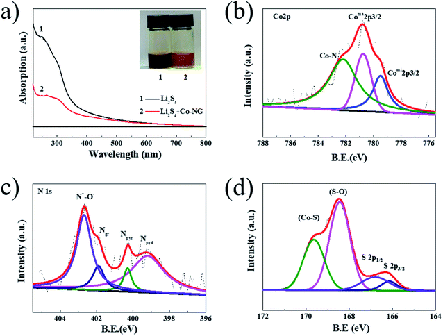 | ||
| Fig. 4 (a) UV-vis absorption spectra and photograph (inset) of Li2S4 solutions with and without Co–N–G. (b) Co 2p, (c) N 1s and (d) S 2p XPS spectra of the Li2S4-absorbed samples. | ||
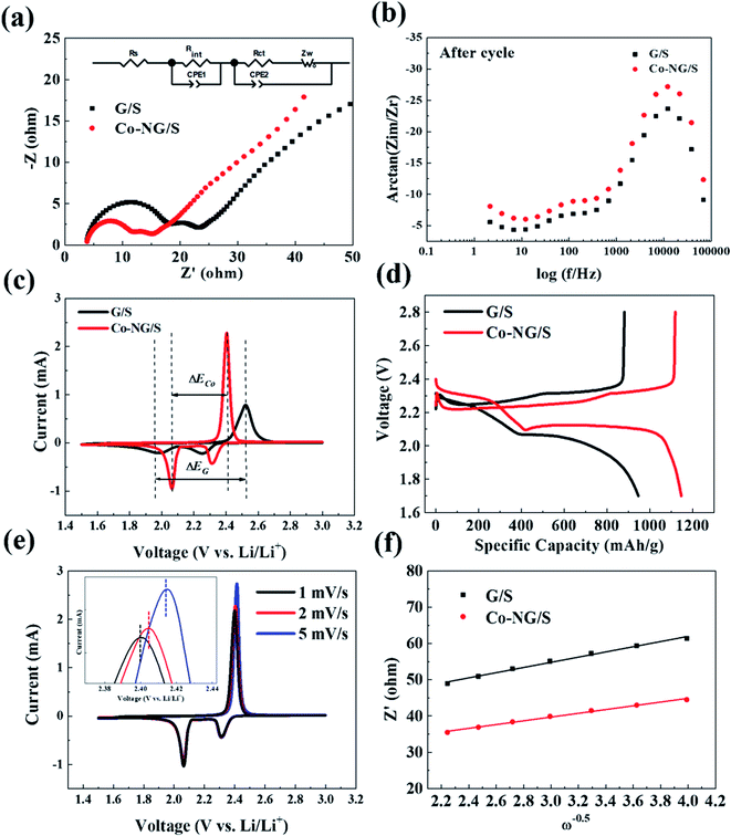
The overall electrochemical performances are usually used to demonstrate the catalytic effect for the conversion of lithium polysulfides by analyzing their conversion reaction rate and the lithium-ion diffusivity. The electrochemical measurements were performed using a sulfur areal loading of 3.6 mg cm−2 at a potential of 1.7 to 2.8 V (vs. Li/Li+).55 As the reference sample, the cell with a pristine graphene electrode was fabricated under the same conditions. The Nyquist plot and the phase-Bode plot were measured after 50 cycles, as shown in Fig. 5a and b, respectively. The ohmic resistance (Rs) comes from the electrolyte resistance. This semi-circle at HF (100 kHz–1 kHz) is associated with the interfacial resistance (Rint) of the Li surface or the contact points between carbon and sulfur. This semi-circle at MF (1 kHz to 1 Hz) is related to the polysulfide is formed in the electrolyte, indicating the charge transfer reaction of the actual reduction/oxidation reaction of polysulfide. The (Rct) charge-transfer resistance reflects the charge-transfer process at the interface between the conductive agent and the electrolyte. The fitting values are presented in Table 1. The Co–N–G electrode presented a lower Rct than that of the G/S electrode. In an Li–S battery, a lower Rct is often related to less cumulative agglomerates, indicating an increase in electrical conductivity on the cathode surface, enhancement ion transportation, and a rapid ionic exchange process.56 Thus, the EIS results suggest that the Co and N catalysts effectively improved the reaction kinetics in the Li–S battery.
| Sample | Rs/Ω | Rint/Ω | Rct/Ω |
|---|---|---|---|
| G/S | 6.024 | 8.397 | 13.27 |
| Co–N–G/S | 3.888 | 3.708 | 6.226 |
The oxidation–reduction reactions on the electrodes were explored via CV tests, as shown in Fig. 5c. For the Co–N–G cell, there are two reduction peaks and one oxidation peak, corresponding to the conversion of sulfur to LiPSs, reduction of short-chain LiPSs to Li2S and the oxidation of Li2S to sulfur, respectively. By comparison, a narrower potential hysteresis and higher peak currents and area were observed for the Co–N–G electrode than that in the pristine graphene electrode, representing the rapid catalytic ability of the doped Co–N. The potential difference ΔECo–N–G between the oxidation and reduction platform of the Co–N–G/S cell is 0.34 V, and the electrode potential difference ΔEG for the pristine cell is 0.51 V. The polarization of the Co–N–G battery is relatively weaker, proving that the introduction of the Co and N catalysts relieved the electrochemical energy barrier due to their superior catalytic effect.57 Besides, the charge–discharge platform curves are exhibited in Fig. 5d, which are consistent with the CV results. To further explore the reaction kinetics, the transport rate of lithium ions was analyzed by CV scanning at different rates, which was carried out in the low-frequency region in the impedance map.58 With an increase in the CV scan rate from 0.1 to 0.5 mV s−1 (Fig. 5e), the redox-reduction peak exhibited a slight shift, confirming the catalytic activity of the Co atom. To calculate the diffusion coefficient of lithium ions, the fitted Z′ and ω−0.5 of the electrodes after 50 cycles were calculated, where Z′ is the actual measured Warburg impedance and ω represents the angular frequency, following a linear function relationship, as shown in eqn (1). The specific value of the Weber factor σ was obtained by calculating the slope in Fig. 5f. The lithium-ion diffusion coefficient DLi+ can be obtained using eqn (2), the absolute temperature T, the gas constant R, the Faraday constant F, the normalized area of the positive electrode A, the lithium-ion concentration CLi+, and the number of electrons participating in the reaction.59 The lithium-ion diffusion coefficients are presented in Table 2, indicating that the Co–N–G electrode has fast ion transport. Thus, the results of the electrochemical measurements prove that the Co–N–G/S cell has lower resistances, lower electrode potential difference, ΔE, and faster ion transport than that of the G/S cell, resulting in a rapid electronic and ionic exchange process in the Co–N–G/S cell. Thus, it can be concluded that the Co–N–G electrode exhibits significant catalytic effect to enhance the reaction kinetics in Li–S batteries.
| Z′ = Rs + Rct + σω−0.5 | (1) |
 | (2) |
| G/S | Co–N–G/S | |
|---|---|---|
| σ | 7.15 | 5.17 |
| DLi+/10−17 (cm2 s−1) | 3.83 | 7.32 |
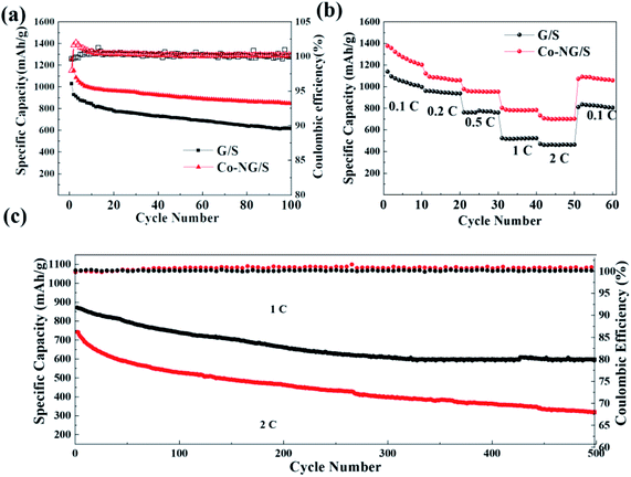
Base on the superior function of Co–N–G in catalytic action for improving the kinetics of the conversion reaction, the Li–S battery exhibited an excellent performance. The Co–N–G electrode battery delivered a high capacity of 1255.7 mA h g−1 with almost 64% retention of its initial capacity at 0.2C after 100 cycles (Fig. 6a). The good rate performance is shown in Fig. 6b, where even at 2C, the Co–N–G electrode endowed the batteries with a high reversible capacity of 704.6 mA h g−1, which is almost twice that in the pristine batteries. This further confirms the superior catalytic activity of the active Co and N catalysts in trapping the immobilized LiPSs and the enhanced kinetic conversion of the LiPSs on Co–N–G. To further explore the Co–N–G battery, its long cycling performance at a larger current density of 1C and 2C was investigated (Fig. 6c). Interestingly, the battery with Co–N–G had the highest initial capacity of 821.9 mA h g−1 at 1C and 736.0 mA h g−1 at 2C, with about 60% and 45% capacity retention after 500 cycles, respectively. The enhanced performance is ascribed to the accelerated conversion reaction of polysulfide intermediates, resulting from the significant adsorption ability and catalysis of Co–N–C.
4. Summary
In conclusion, the solvothermal method using formamide as the reaction medium successfully compounded Co–N–G with a uniform distribution of Co and N catalysts on graphene, which was utilized as a host material in the electrode of Li–S batteries. The well-distributed nano catalysts with a large binding energy not only could anchor the LiPSs by physical and chemical adsorption, but also reversibly catalyze the conversion of LiPSs. The electrochemical experiments revealed that the ionic diffusion barrier was significantly reduced by the catalysts. Owing to the catalytic activity function and enhancement in reaction kinetics, the Li–S battery with the Co–N–G cathode exhibited high cycling capability and excellent rate performance, displaying a reversible capacity of 1225.7 mA h g−1 at 0.2C, with a high capacity retention of 64% after 100 cycles.Conflicts of interest
There are no conflicts to declare.Acknowledgements
This work was supported by the National Natural Science Foundation of China [51802026]; Natural Science Foundation of Jilin Province [20200201094JC, 20190103023JH, 20200201254JC]; Education Department of Jilin Province [JJKH20210825KJ, JJKH20200770KJ, JJKH20200763KJ].References
- D. Bradley, Educ. Chem., 2010, 47, 124–125 Search PubMed.
- L. Kai, L. Yayuan, L. Dingchang, P. Allen and C. Yi, Sci. Adv., 2018, 4, eaas9820 CrossRef PubMed.
- A. Manthiram, ACS Cent. Sci., 2017, 3, 1063–1069 CrossRef CAS PubMed.
- K. Turcheniuk, D. Bondarev, V. Singhal and G. Yushin, Nature, 2018, 559, 467–470 CrossRef CAS PubMed.
- R. Marom, S. F. Amalraj, N. Leifer, D. Jacob and D. Aurbach, J. Mater. Chem., 2011, 21, 9938–9954 RSC.
- T. Maihom, S. Kaewruang, N. Phattharasupakun, P. Chiochan, J. Limtrakul and M. Sawangphruk, J. Phys. Chem. C, 2018, 122, 7033–7040 CrossRef CAS.
- W. Ren, W. Ma, S. Zhang and B. Tang, Energy Storage Mater., 2019, 23, 707 CrossRef.
- M. Shaibani, M. S. Mirshekarloo, R. Singh, C. D. Easton and M. Majumder, Sci. Adv., 2020, 6, eaay2757 CrossRef CAS PubMed.
- D. Larcher and J. M. Tarascon, Nat. Chem., 2015, 7, 19–29 CrossRef CAS PubMed.
- Y. Zhang, Z. Gao, N. Song, J. He and X. Li, Mater. Today Energy, 2018, 9, 319–335 CrossRef.
- B. Dunn, H. Kamath and J. M. Tarascon, Science, 2011, 334, 928–935 CrossRef CAS PubMed.
- R. Elazari, G. Salitra, Y. Talyosef, J. Grinblat, C. Scordilis-Kelley, A. Xiao, J. Affinito and D. Aurbach, J. Electrochem. Soc., 2010, 157, A1131 CrossRef CAS.
- J. Zhang, H. Huang, J. Bae, S. H. Chung, W. Zhang, A. Manthiram and G. Yu, Small Methods, 2018, 1700279 CrossRef.
- J. G. Wang, K. Xie and B. Wei, Nano Energy, 2015, 15, 413–444 CrossRef CAS.
- G. Zhou, S. Pei, L. Li, D.-W. Wang and S. Wang, Adv. Mater., 2014, 26, 625–631 CrossRef CAS PubMed.
- Y. V Mikhaylik and J. R. Akridge, J. Electrochem. Soc., 2004, 151, A1969 CrossRef.
- C. Dai, J.-M. Lim, M. Wang, L. Hu, Y. Chen, Z. Chen, H. Chen, S.-J. Bao, B. Shen, Y. Li, G. Henkelman and M. Xu, Adv. Funct. Mater., 2018, 28, 1704443–1704451 CrossRef.
- H. J. Peng, J. Q. Huang and Q. Zhang, Chem. Soc. Rev., 2018, 46, 5237 RSC.
- Y. Xiang, J. Li, J. Lei, D. Liu, Z. Xie, D. Qu, K. Li, T. Deng and H. Tang, ChemSusChem, 2016, 9, 3023 CrossRef CAS PubMed.
- S. H. Chung, C. H. Chang and A. Manthiram, ACS Nano, 2016, 10462 CrossRef CAS PubMed.
- D. Aurbach, J. Electrochem. Soc., 2018, 165, 2020 CrossRef.
- G. Li, J. Sun, W. Hou, S. Jiang, Y. Huang and J. Geng, Nat. Commun., 2016, 7, 10601 CrossRef CAS PubMed.
- X. Wang, G. Li, J. Li, Y. Zhang and Z. Chen, Energy Environ. Sci., 2016, 9, 2533 RSC.
- E. Umeshbabu, B. Zheng and Y. Yang, Electrochem. Energy Rev., 2019, 2, 199 CrossRef CAS.
- M. Zhao, B. Li, H. Peng, H. Yuan, J. Wei and J. Huang, Angew. Chem., Int. Ed., 2020, 59, 12636 CrossRef CAS PubMed.
- W. Zeng, M. C. Cheng and K. Y. Ng, Electrochim. Acta, 2019, 319, 511–517 CrossRef CAS.
- W. Chen, Y. Hu, W. Lv, T. Lei and C. Yan, Nat. Commun., 2019, 10, 4973 CrossRef PubMed.
- Z. Yu, M. Liu, D. Guo, J. Wang, X. Chen, J. Li, H. Jin, Z. Yang, X. Chen and S. Wang, Angew. Chem., Int. Ed., 2020, 59, 6406 CrossRef CAS PubMed.
- A. Fu, C. Wang, F. Pei, J. Cui, X. Fang and N. Zheng, Small, 2019, 15, 1804786 CrossRef PubMed.
- B. Zhang, R. Qin, R. R. Li and R. P. Gao, Energy Environ. Sci., 2010, 3, 1531–1537 RSC.
- L. Zhang, D. Liu, Z. Muhammad, F. Wan and J. Chen, Adv. Mater., 2019, 31, 1903955 CrossRef CAS PubMed.
- Y. Xu, W. Tu., B. Zhang, S. Yin, Y. Huang., M. Kraft. and R. Xu, Adv. Mater., 2017, 29, 1605957 CrossRef PubMed.
- X. R. Wang, J. Y. Liu., Z. W. Liu., W. C. Wang, J. Luo, X. P. Han, X. W. Du., S. Z. Qiao. and J. Yang, Adv. Mater., 2018, 30, 1800005 CrossRef PubMed.
- P. Chen, Z. Wang, B. Zhang, J. Zhao and Z. Su, Int. J. Energy Res., 2020, 44, 3231 CrossRef CAS.
- P. Chen, Z. Wang, B. Zhang, H. Liu, W. Liu, J. Zhao, Z. Ma, W. Dong and Z. Su, RSC Adv., 2020, 10, 4538–4544 RSC.
- G. Cao, Z. Wang, D. Bi, J. Zheng, Q. Lai and Y. Liang, Chem.–Eur. J., 2020, 12, 10314 CrossRef PubMed.
- Z. Du., X. Chen., W. Hu., C. Chuang., S. Xie, A. Hu., W. Yan., X. Kong., X. Wu. and H. Ji, J. Am. Chem. Soc., 2019, 141, 3977–3985 CrossRef CAS PubMed.
- Y. Li, P. Zhou, H. Li, T. Gao, L. Zhou, Y. Zhang, N. Xiao, Z. Xia, L. Wang and Q. Zhang, Small Methods, 2020, 4, 3 Search PubMed.
- Z. H. Zhuang, Q. Kang, D. S. Wang and Y. D. Li, J. Nano Res., 2020, 13, 1856–1866 CrossRef CAS.
- Y. Liang, C. Zhao, H. Yuan, Y. Chen, W. Zhang, J. Huang, D. Yu, Y. Liu, M. Titirici and Y. Chueh, InfoMat., 2019, 1, 6 CrossRef CAS.
- F. Pei, L. Lin, D. Ou, Z. Zheng, S. Mo, X. Fang and N. Zheng, Nat. Commun., 2017, 8, 482 CrossRef PubMed.
- L. Fang, Z. Feng, L. Cheng, R. E. Winans and T. Li, Small Methods, 2020, 4, 10 CrossRef.
- J. Wang, L. Jia, S. Duan, H. Liu and Y. Zhang, Energy Storage Mater., 2020, 28, 375 CrossRef.
- M. P. Yu, J. S. Ma, H. Y. Ye, H. Q. Song, D. X. Wang, Y. T. Zhao, W. Gong and H. Qiu, Mater. Chem. Front., 2019, 3, 1807–1815 RSC.
- M. Yu, R. Li, M. Wu and G. Shi, Energy Storage Mater., 2015, 1, 51 CrossRef.
- H. Wang, Y. Yang, Y. Liang, J. T. Robinson, Y. Li, A. Jackson, Y. Cui and H. Dai, Nano Lett., 2011, 11, 2644–2647 CrossRef CAS PubMed.
- Y. Xiao, Z. Yi, H. Zeng, W. Zhang, B. Tian and Y. Deng, J. Alloys Compd., 2019, 787, 1356 CrossRef CAS.
- P. Yin, T. Yao, Y. Wu, L. Zheng, Y. Lin, W. Liu, H. Ju, J. Zhu, X. Hong and Z. Deng, Angew. Chemie., 2016, 55, 10800 CrossRef CAS PubMed.
- X. Zhou, Q. Liao, T. Bai and J. Yang, J. Mater. Sci., 2017, 52, 7719–7732 CrossRef CAS.
- O. Ogoke, S. Hwang, B. Hultman, M. Chen and G. Wu, J. Mater. Chem. A, 2019, 7, 13389 RSC.
- D. Cheng, Y. Zhao, X. Tang, T. An and T. Fan, Carbon, 2019, 149, 750–759 CrossRef CAS.
- W. Ren, W. Ma, M. Umair, S. Zhang and B. Tang, ChemSusChem, 2018, 11, 16 Search PubMed.
- M. Jin, F. He, L. Cai, X. Huang, H. Liu and P. Li, J. Power Sources, 2016, 328, 536–542 CrossRef.
- S. Jiang, S. Huang, M. Yao, J. Zhu, L. Liu and Z. Niu, Chin. Chem. Lett., 2020, 31, 209–214 Search PubMed.
- H. Ye and J. Y. Lee, Small Methods, 2020, 4, 1900864 CrossRef CAS.
- Z. Deng, Z. Zhang, Y. Lai, J. Liu, J. Li and Y. Liu, J. Electrochem. Soc., 2013, 160, A553–A558 CrossRef CAS.
- W. A. Jian, B. Lj, C. Jz, A. Qx, W. B. Chong, D. Kz, E. Hl, C. Hz, D. Jl and Y. A. Jin, Energy Storage Mater., 2019, 18, 246–252 CrossRef.
- B. Li, L. Kong, C. Zhao, Q. Jin and J. Huang, InfoMat., 2019, 1, 9 Search PubMed.
- X. Du, W. He, X. Zhang, Y. Yue, H. Liu, X. Zhang, D. Min, X. Ge and Y. Du, J. Mater. Chem., 2012, 22, 5960–5969 RSC.
| This journal is © The Royal Society of Chemistry 2022 |

