 Open Access Article
Spoiling of tunability of on-substrate graphene strip grating due to lattice-mode-induced transparency
Fedir O. Yevtushenko *a,
Sergii V. Dukhopelnykov
 ab,
Yuriy G. Rapoport
 c,
Tatiana L. Zinenko
 ad and
Alexander I. Nosich
 *a
*a
aLaboratory of Micro and Nano Optics, Institute of Radio-Physics and Electronics NASU, Kharkiv, 61085, Ukraine. E-mail: anosich@yahoo.com
bDepartment of Applied Mathematics, V. N. Karazin Kharkiv National University, Kharkiv, 61022, Ukraine
cSchool of Physics, Taras Shevchenko National University of Kyiv, Kyiv, 01601, Ukraine
dDepartment of Quasi-Optics, Institute of Radio-Physics and Electronics NASU, Kharkiv, 61085, Ukraine
First published on 4th February 2022
Abstract
We report a prediction of the optical effect apparently not discussed earlier. As known both from theory and experiment, the gratings of flat graphene strips lying on dielectric substrates display moderate-Q resonances on the strip plasmon modes in the H-polarization case. In the plasmon resonances, high reflectance and absorbance are observed. These characteristics are tunable with the aid of the graphene chemical potential, which controls the plasmon-mode frequency. However, if this frequency coincides with the high-Q lattice-mode frequency, a narrow-band regime of electromagnetically induced transparency (EIT) appears. A new point in our finding is that, in the EIT regime, the tunability of the reflectance and absorbance of a grating of narrow graphene strips get spoiled profoundly. This is established using a full-wave meshless code based on the method of analytical regularization, which leads to a Fredholm second-kind matrix equation that guarantees the code convergence. Numerical results are presented for the strip width and period, having the microsize dimensions so that all resonances lie in the THz range. However, the same effect takes place in the infrared range for narrower strips and smaller periods. The lattice modes are caused by the periodicity and can have ultra-high Q-factors; however, they do not exist if the substrate is absent. The loss of tunability at EIT is explained by the lattice-mode field pattern, which has deep E-field minima at the strips.
Electromagnetic-wave devices and systems working in the terahertz, infrared, and visible-light ranges depend critically on a progress in nanotechnologies. In this connection, the appearance of graphene has opened numerous exciting opportunities. This is because graphene has high electron mobility, controlled with the aid of DC biasing.1–4 Owing to this, a surface plasmon-guided wave can propagate in a tunable manner on a sheet of graphene in the terahertz and infrared ranges – this is at two orders lower frequencies than on the metal surface.5 On the patterned graphene, such a surface wave creates Fabry–Perot resonances, i.e., plasmon modes, the frequencies of which are also tunable using the chemical potential. Therefore, it is no surprise that graphene elements are proposed and used in various frequency-selective antennas, filters, absorbers and sensors.1–10
Graphene-strip gratings are among the most important configurations of the patterned graphene, considered in ref. 6, 9, 11 and 12 (see also references therein), and used in the real-life tunable plasmonic mid-infrared biosensors3 and THz nanoantennas.4 Recently, we have analyzed the scattering and absorption of THz waves by such a grating, lying on a dielectric substrate,13 using the method of analytical regularization based on the explicit solution of the Riemann–Hilbert Problem. This meshless technique has an advantage in the absence of numerical integrations needed to fill in the resulting matrix and possesses a mathematically guaranteed convergence. Owing to the convergence, the accuracy of computations can be easily brought to the level of machine precision.
Using this extremely fast and reliable numerical code, we have studied in ref. 13 the interplay, in the entire THz range of the resonances in the scattering and absorption caused by the H-polarized natural modes of three types: low-Q slab modes (SMs) of the substrate, moderate-Q plasmon modes (PMs) of the graphene strips, and ultrahigh-Q lattice modes (LMs). In this research, the EIT regimes appeared if the PM frequencies coincided with the frequencies of sharper LM resonances. Now, we report on the important details of this regime that have not been noticed earlier.
The LM resonances, which do not exist on the suspended air graphene-strip gratings, need a brief introduction. They have been frequently overlooked or neglected earlier but became exposed recently.8,11,14 The LMs are specific natural modes of the gratings as periodic open resonators first reported in ref. 15 and then largely forgotten. Now, they attract increasingly wider attention.16–19 This is because in theory they may have whatever high (albeit still finite) Q-factors;14 in our case, this happens if the substrate gets thinner.13 More specifically, if h → 0, then the complex LM poles of the field as a function of the frequency tend towards the purely real-valued frequencies of Rayleigh Anomalies (RAs), which are the field branch points. The other natural modes of our metasurface, namely the plasmon modes of the strips and the slab modes of the substrate, do not have such a property. The LM fields, which dominate in the resonances are built as either running Floquet harmonic (at inclined incidence) or a standing wave of two such harmonics (at normal incidence). These harmonics remain non-propagating in the host medium and hence their amplitudes, scaling as Q-factors, also grow unlimitedly.14 Note that the use of rougher computational instruments, e.g., commercial codes, does not allow an accurate enough quantification of the extremely fine LM resonances. As a consequence, the LMs are sometimes misinterpreted as having infinite Q-factors.
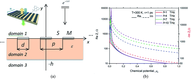
The analyzed metasurface is shown in Fig. 1(a). This is an infinite grating of monolayer graphene strips lying on the upper surface of a dielectric-slab substrate of thickness h and relative permittivity ε. The strips have the widths d and the period is p. The H-polarized plane wave is incident normally from above and depends on time as e−iωt.
The graphene complex-valued surface impedance, Z, is the inverse of the surface electron conductivity, and the latter is available from the Kubo formalism.5 Note also that non-local effects in conductivity can be neglected if the strip is wider than 100 nm. Besides, in the THz range (in fact, up to the visible light) only the conductivity intraband part, which is the Drude-like term, can be kept while the interband part can be neglected,5 so that
| Z ≈ Z0(−iω + τ−1)Ω−1 | (1) |
Ω = Z0q2ecBT(πℏ2)−1{μc(cBT)−1 + 2![[thin space (1/6-em)]](https://www.rsc.org/images/entities/char_2009.gif) ln[1 + e−μc/(cBT)]}, ln[1 + e−μc/(cBT)]},
| (2) |
Z0 is the free-space impedance, T is the temperature, qe is the electron charge, cB is the Boltzman constant, ℏ is the reduced Planck's constant, and μc is the chemical potential. The variation of the real and imaginary parts of Z with chemical potential is demonstrated in Fig. 1(b).
In computations, we took the graphene parameters as T = 300 K and τ = 1 ps. The latter choice helped to emphasize the PM resonances (today, CVD-graphene samples show, at best,τ = 0.5 ps). Here, we selected the strip width, grating period, and substrate thickness in tens of micrometers. This placed the frequencies of all natural modes in the terahertz range. However, similar effects occurred in the near-infrared region if the mentioned parameters were taken in the tens of nanometers.
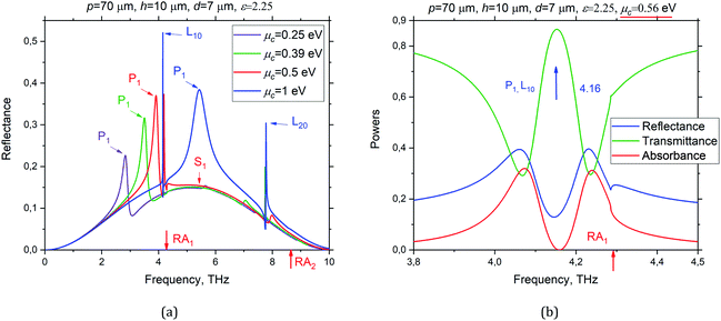
It is known that the DC tunability of conductivity is graphene's most important feature for applications. The plots in Fig. 2(a) correspond to the normal incidence. They showed the behavior of the reflectance of the studied metasurface with p = 70 μm, d = 7 μm and h = 10 μm as a function of the THz frequency at four different values of the graphene chemical potential, μc = 0.25 eV, 0.39 eV, 0.5 eV, and 1 eV.
Here, the marks RA1,2 indicate the positions of the first and second Rayleigh Anomalies, where the ±1-st and ±2-nd diffraction orders start propagating. Broad bell-like resonance at 5 THz is caused by the lowest SM, which is S1. Its frequency is controlled by h and ε and does not depend on μc. The sharp spikes just below RAs are the LM resonances L10 and L20, respectively. They are controlled by the grating period p and the wavelength of the lowest guided mode of the dielectric slab (see ref. 13 for details). A moderate-Q peak, which shifts to the blue for the larger chemical potentials is for the PM resonance, P1. Note that the latter peak had the Fano shape if it sat on the slope of the broader S1 peak.
The PM frequencies and associated Q-factors of a single graphene strip can be found analytically, viewing the strip as a one-dimensional surface-wave Fabry–Perot resonator, i.e., neglecting the radiation losses of PMs. Then, the approximate characteristic equation is
| sin(gplasd + ψ) = 0, | (3) |
As shown in10, the value ψ = π/4 provides the best fit and, if |Z| ≫ Z0, then (see Appendix in that paper),
| gplas ≈ ik(ε + 1)Z/Z0, | (4) |
Then, we obtained the following expressions for the PM resonance frequencies and Q-factors:
 | (5) |
 | (6) |
Assuming additionally that μc ≫ cBT, we can conclude that both the graphene-strip PM frequencies and their Q-factors scale as  . This behavior is clearly visible on the color maps of the reflectance, transmittance and absorbance of the same metasurface, as shown in Fig. 3.
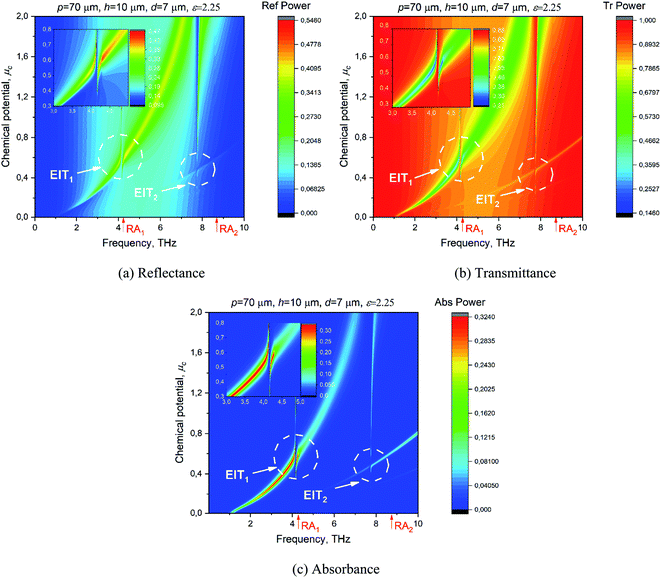 | ||
| Fig. 3 The color maps of the reflectance (a), transmittance (b) and absorbance (c) versus the frequency and chemical potential at the normal incidence of the H-polarized plane wave at the same grating as in Fig. 2. | ||
These maps demonstrate a complicated interplay of the tunable medium-Q plasmon-mode resonances, P1, P2, with the fixed-frequency high-Q lattice-mode resonances, L10, L20, if their frequencies coincide. In addition, the background was set by the fixed-frequency very-low-Q resonance S1. The cuts of these maps at μc = 0.56 eV are shown in Fig. 2(b). Here, the broad peak of high reflection on P1 is split by a narrower band of very low reflection on L10, accompanied by the negligible absorption – this is the EIT-1 regime. Similarly, however, a weaker EIT effect occurred at a higher frequency, where P2 hybridizes with L20, marked as EIT-2. Note that earlier the EIT effect was reported for the gratings of thin silver nanostrips and nanowires in the visible-light range;14 it appeared due to the coupling between the low-Q plasmon mode and the ultrahigh-Q lattice mode if their frequencies coincided.
It is known that EIT takes place in electric circuits and even in mechanics when two resonance contours are coupled: one with low Q-factor and another with high Q-factor, and their frequencies coincide.20 More recently, all-optical EIT effects have started attracting attention;21 they can be found both in configurations with two coupled cavities and within a single cavity. In our case, each graphene strip is an open cavity, supporting the plasmon modes, and the whole grating is also an open cavity, supporting the lattice modes; they are optically coupled. What is less expected is that the absorbance of the graphene-strip grating at EIT is extremely low. Moreover, the cuts through the maps of Fig. 3 at the frequency of EIT-1 and EIT-2, as shown in Fig. 4(a) and (b), respectively, reveal practically the total loss of tunability of the metasurface with respect to the chemical potential. This combined effect has not been, apparently, reported earlier and is explained by the same reason, which became clear after visualizing the near-field pattern at EIT, i.e., at the LM frequency.
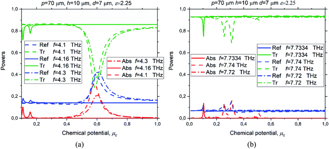 | ||
| Fig. 4 The reflectance, transmittance and absorbance of the on-substrate graphene strip grating of the same parameters as in Fig. 2–3 versus the chemical potential of graphene at the frequencies of 4.1 THz, 4.16 THz (EIT-1 regime) and 4.3 THz (a) and 7.72 THz, 7.7334 THz (EIT-2 regime) and 7.74 THz (b). | ||
In Fig. 5(a), such a pattern is shown for the absolute value of the magnetic field (normalized by the incident plane wave magnitude) at the L10 frequency.
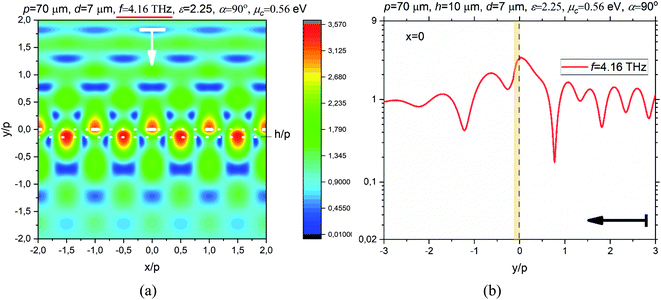 | ||
| Fig. 5 The magnetic field pattern on four periods of graphene-strip grating at the frequency of EIT-1 due to the hybridization of the LM resonance on L10 and the PM resonance on P1 (a), and the magnetic field absolute value along the normal to the strip midpoint, x = 0, at this frequency (b), for the same parameters as in Fig. 2–4 and μc = 0.56 eV. | ||
This pattern reveals two bright spots on the unit period: one at the strip and the other at the slot. These two spots have opposite phases, and such a standing wave was a signature of the first-order LM.14 As already mentioned, according to14 at the L10 resonance frequency this standing wave was formed by the ±1-st Floquet harmonics, which dominated over all other harmonics with amplitudes scaling as the Q-factor, however remained attenuating at |y| → ∞.
The cut of the near magnetic field magnitude through the strip center (Fig. 5(b)) also shows a maximum at the strip, together with the field continuity. Now, one should remember that, in the case of the H-polarization, the electric field vector is within a constant the gradient of the magnetic field z-component. Therefore, the bright spots of electric field appear at the nods of the magnetic field and vice versa. This means that, in the LM resonance, the imperfect graphene strips (which are one-tenth of the period in our case) sit in the deep minima of the electric field. Besides, as the magnetic field in EIT is continuous across the strip, the induced electric current is close to zero. These LM-field features minimize the graphene strip losses, which are a product of Re Z and the integral, over the strip width, of the squared absolute value of the current.
In addition, these features spoil the tunability of the grating scattering characteristics, in the sense that the DC bias in EIT has no effect on the transmittance-to-reflectance ratio of our metasurface. Alternatively, in the EIT regime, the graphene tunability as a material becomes irrelevant because of a stronger all-optical mechanism, which is enforced by the periodicity.
Such a behavior is observed so far as the strips are narrow, narrower than approximately a quarter of the period if the EIT is associated with the lowest lattice mode, L10. If the strips are wider and approach a half of the period, then certain absorption appears in the form of small bumps at the LM frequency, and the bump height is larger for the larger chemical potential. This is because, if the strips are wide, then their edges “stretch out” of the near-zero E-field spots of the lattice mode L10 and therefore some current is induced that leads to absorption. In the EIT regimes associated with the higher-order lattice modes, L20, L30, etc., the strips have to be even narrower to spoil the tunability because these mode E-fields have 4, 6, etc., near-zero spots on the period.
This interpretation is supported by the near magnetic field pattern and its corresponding y-dependence, as presented in Fig. 6(a) and (b), respectively.
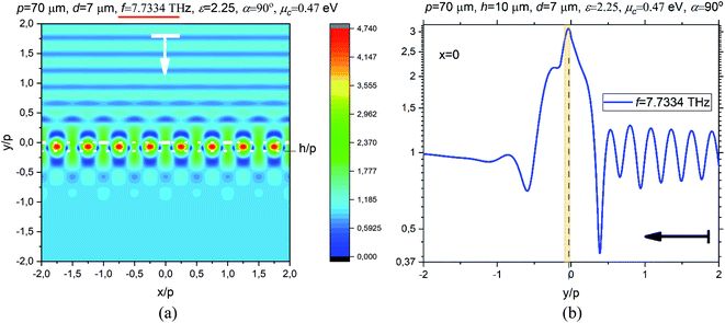 | ||
| Fig. 6 The magnetic field pattern on four periods of graphene-strip grating at the frequency of EIT-2 due to the hybridization of the LM resonance on L20 and the PM resonance on P3 (a), and the magnetic field absolute value along the normal to the strip midpoint, x = 0, at this frequency (b), for the same parameters as in Fig. 2–4 and μc = 0.47 eV. | ||
Although the tunability of the scattering from the studied grating is lost at EIT, the effect of the chemical potential is still present even then, however, in a different manner. From (1) and (2), for the larger chemical potentials, graphene's bulk absorption scales approximately as the inverse chemical potential. Due to this, the IET band gets slightly narrower if the potential is larger.
In conclusion, we have reported the narrow-band all-optical electromagnetically induced transparency regimes, appearing due to the plane-wave excitation of the high-Q lattice modes on a dielectric substrate-backed graphene-strip grating. As we have found, in these regimes, the tunability of the scattering from the grating can be spoiled because of the specific features of the lattice-mode field. This phenomenon may cause the failure of the sensors consisting of such graphene strip gratings, particularly, operating in the reflection mode, both in the infrared and THz parts of spectrum. We believe that these research results are helpful for sensor design as they enable allocating the frequency band without the occurrence of EIT.
We have considered only the H-polarization case because in the E-polarization the DC-tunable plasmon modes and resonances associated to them do not exist, although both lattice modes and slab modes are present. Note that the lattice modes, in either polarization, do not exist on a graphene-strip grating in the free space;6 however, they exist on such a grating supported by a thin substrate;13 their Q-factors, for infinite grating, grow up unlimitedly if the substrate gets thinner, or its contrast with the host medium vanishes.13 Taking this into account, we would like to stress that accurate assessment of such fine resonance effects is possible only with equally fine numerical techniques, more accurate than today's commercial codes.
Funding
This work was funded, in part, by the National Research Foundation of Ukraine, grant #2020-02-0150, and the National Academy of Sciences of Ukraine, project #6541230.Conflicts of interest
The authors declare no conflicts of interest.References
- F. J. Garcia de Abajo, Graphene plasmonics: challenges and opportunities, ACS Photonics, 2014, 1(3), 135–152 CrossRef CAS.
- T. Low and P. Avouris, Graphene plasmonics for terahertz to mid-infrared applications, ACS Nano, 2014, 8(2), 1086–1101 CrossRef CAS PubMed.
- D. Rodrigo, O. Limaj, D. Janner, D. Etezadi, F. Abajo, V. Pruneri and H. Altug, Mid-infrared plasmonic biosensing with graphene, Science, 2015, 349(6244), 165–168 CrossRef CAS PubMed.
- Z. Ullah, G. Witjaksono, I. Nawi, N. Tansu, M. Khattak and M. Junaid, A review on the development of tunable graphene nanoantennas for terahertz optoelectronic and plasmonic applications, Sensors, 2020, 20(5), 1401 CrossRef CAS PubMed.
- G. W. Hanson, Dyadic Green's functions and guided surface waves for a surface conductivity model of graphene, J. Appl. Phys., 2008, 103, 064302 CrossRef.
- O. V. Shapoval, J. S. Gomez-Diaz, J. Perruisseau-Carrier and J. R. Mosig, Integral equation analysis of plane wave scattering by coplanar graphene-strip gratings in the THz range, IEEE Trans. Terahertz Sci. Technol., 2013, 3(5), 666–673 Search PubMed.
- W. Fuscaldo, P. Burghignoli, P. Baccarelli and A. Galli, Efficient 2-D leaky-wave antenna configurations based on graphene metasurfaces, Int. J. Microw. Wireless Techn., 2017, 9(6), 1293–1303 CrossRef.
- T. L. Zinenko, A. Matsushima and A. I. Nosich, Surface-plasmon, grating-mode and slab-mode resonances in THz wave scattering by a graphene strip grating embedded into a dielectric slab, IEEE J. Sel. Top. Quantum Electron., 2017, 23(4), 4601809 Search PubMed.
- M. Kaliberda, L. Lytvynenko and S. Pogarsky, Singular integral equations in diffraction by multilayer grating of graphene strips in the THz range, EPJ Appl. Phys., 2018, 82(2), 21301 CrossRef CAS.
- S. V. Dukhopelnykov, R. Sauleau and A. I. Nosich, Integral equation analysis of terahertz backscattering from circular dielectric rod with partial graphene cover, IEEE J. Quantum Electron., 2020, 56(6), 8500208 CAS.
- T. L. Zinenko, A. Matsushima and A. I. Nosich, Terahertz range resonances of metasurface based on double grating of microsize graphene strips inside dielectric slab, Proc. R. Soc. A, 2020, 476(2240), 20200173 CrossRef.
- R.-B. Hwang, A theoretical design of evanescent wave biosensors based on gate-controlled graphene surface plasmon resonance, Sci. Rep., 2021, 11, 1999 CrossRef CAS PubMed.
- F. O. Yevtushenko, S. V. Dukhopelnykov, T. L. Zinenko and Y. G. Rapoport, Electromagnetic characterization of tuneable graphene-strips-on-substrate metasurface over entire THz range: Analytical regularization and natural-mode resonance interplay, IET Microwaves, Antennas & Propagation, 2021, 15(10), 1225–1239 Search PubMed.
- V. O. Byelobrov, T. L. Zinenko, K. Kobayashi and A. I. Nosich, Periodicity matters: grating or lattice resonances in the scattering by sparse arrays of sub-wavelength strips and wires, IEEE Antennas Propag. Mag., 2015, 57, 34–45 Search PubMed.
- A. Hessel and A. A. Oliner, A new theory of Wood's anomalies on optical gratings, Appl. Opt., 1965, 4(10), 1275–1297 CrossRef.
- V. G. Kravets, A. V. Kabashin, W. L. Barnes and A. N. Grigorenko, Plasmonic surface lattice resonances: a review of properties and applications, Chem. Rev., 2018, 118, 5912–5951 CrossRef CAS PubMed.
- V. V. Yachin, T. L. Zinenko and S. V. Mizrakhy, Resonance enhancement of Faraday rotation in double-periodic gyromagnetic layers analyzed by the method of integral functional, J. Opt. Soc. Am. B, 2018, 35, 851–860 CrossRef CAS.
- G. W. Castellanos, P. Bai and J. Gómez Rivas, Lattice resonances in dielectric metasurfaces, J. Appl. Phys., 2019, 125, 213105 CrossRef.
- A. D. Utyushev, V. I. Zakomirnyi and I. L. Rasskazov, Collective lattice resonances: plasmonics and beyond, Rev. Phys., 2021, 6, 100051 CrossRef.
- C. L. Garrido and M. A. G. Martinez, Classical analog of electromagnetically induced transparency, Am. J. Phys., 2002, 70(1), 37–41 CrossRef.
- Y.-C. Liu, B.-B. Li and Y.-F. Xiao, Electromagnetically induced transparency in optical microcavities, Nanophotonics, 2017, 6(5), 789–811 Search PubMed.
| This journal is © The Royal Society of Chemistry 2022 |

