
 Open Access Article
 This Open Access Article is licensed under a Creative Commons Attribution-Non Commercial 3.0 Unported Licence
Exploration of conjugated π-bridge units in N,N-bis(4-methoxyphenyl)naphthalen-2-amine derivative-based hole transporting materials for perovskite solar cell applications: a DFT and experimental investigation†
Puhang Cheng‡
,
Qian Chen‡,
Hongyuan Liu and
Xiaorui Liu *
*
Key Laboratory of Luminescence Analysis and Molecular Sensing, Ministry of Education, School of Chemistry and Chemical Engineering, Southwest University, Chongqing 400715, P. R. China. E-mail: liuxiaorui@swu.edu.cn
First published on 5th January 2022
Abstract
Organic small molecules as hole-transporting materials (HTMs) are an important part of perovskite solar cells (PSCs). On basis of the arylamine-based HTM (e.g. H101), two N,N-bis(4-methoxyphenyl)naphthalen-2-amine derivative-based HTMs (CP1 and CP2) with different conjugated π-bridge cores of fused aromatic ring are designed. The CP1 and CP2 were investigated by DFT and TD-DFT in combination with Marcus theory. The calculated results indicate that the designed CP1 and CP2 have better properties with good stability and high hole mobility compared with the parent H101. To validate the computational model for the screening of N,N-bis(4-methoxyphenyl)naphthalen-2-amine derivative-based HTMs, the promising CP1 and CP2 were synthesized and applied to PSC devices. The results show that the experimental data used in this paper can reproduce the theoretical results, such as frontier molecular orbital energies, optical properties and hole mobility, very well. Among them, the results show that the power conversion efficiency (PCE) of the H101-based PSC device is 14.78%, while the CP1-based PSC shows a better PCE of 15.91%, due to its high hole mobility and uniform smooth film morphology, which ultimately promoted a higher fill factor. Finally, this work shows that the computational model is a feasible way to obtain potential N,N-bis(4-methoxyphenyl)naphthalen-2-amine derivative-based HTMs.
1. Introduction
Perovskite materials [e.g. (FAPbI3)0.875(MAPbBr3)0.075(CsPbI3)0.05(PbI2)0.03] used as light absorbers in perovskite solar cells (PSCs) have excellent photoelectric properties such as high extinction coefficient, long charge-diffusion length, broad optical absorption and high stability.1–5 PSCs as a new type of solar cell have become a highly sought-after terrestrial energy acquisition device due to their rapidly rising power conversion efficiency (PCE). At present, the PCE of PSC devices has reached about 25%.6 In PSC devices, hole-transport materials (HTMs) as hole-transporting layers play a significant role to extract holes from perovskite to metal electrodes (e.g. Ag) in order to reducing non-radiative recombination at the interface, thus achieving high efficiency of devices.7 For the HTMs, organic small molecules have the advantages of accurate molecular weight, high purity, easy adjustment of molecular structure, controllable energy level, etc., and are considered as ideal HTMs for PSC applications.8,9 Therein, the typical HTM of 2,2′,7,7′-tetrakis (N,N-di-p-methoxyphenylamino)-9,9′-spirobifluorene (Spiro-OMeTAD) in PSC device applications can yield high PCE.10,11 However, the core configuration of spiro in Spiro-OMeTAD with the complexity and high cost of synthesis limited the widespread application.12,13 In addition, the hole mobility of the HTMs should be as high as possible, but many organic HTMs including Spiro-OMeTAD, polytriarylamine (PTAA), benzon[1,2-b:3,4-b′:5,6-b′′] trithiophene have a relatively low hole mobility of about 10−5 cm2 V−1 s−1 order of magnitude.14 Therefore, the development of organic HTMs with good stability and high mobility will play an important role in improving the efficiency of PSCs.Arylamine derivatives are an important class of electron-rich groups used to build HTMs with deep HOMO energy levels and high hole mobility, which are widely used in organic optoelectronic devices, such as PSCs, organic light-emitting diodes, organic solar cells and dye-sensitized solar cells, and many other fields.15 Among them, the interaction between the methoxy on the diphenylamine and arylamine derivatives and the perovskite absorber can enhance the coupling between their interfaces.16 For arylamine derivative-based HTMs, the structures are mostly composed of arylamine derivatives as end-site electron-rich groups with different conjugated π-bridges. There exist significant differences in PCE of perovskite solar cells.14 For example, the HTMs of NH-2,6 and NH-2,7 consisting of triphenylamine derivatives as end-site electron-rich groups to connect different conjugated π-bridges, and the PCEs under the same PSC devices and conditions differ significantly, at 18.7% and 14.7%, respectively.17 Therefore, it is important to explore the relationship between conjugated π-bridges on the properties of arylamine derivative HTMs and the efficiency of PSCs to help the design and cost control of efficient HTMs.
In fact, Density Functional Theory (DFT) and Time-Dependent Density Functional Theory (TD-DFT) in combination with Marcus theory are important way to obtain the geometric structure, optical absorption and charge mobility of organic materials.18–22 Some article point out that Marcus theory is used to simulate the charge transfer process, which ignores the high-frequency modes that may play an important role in the charge transfer process.23–26 In our previous work, an important correlation between the theoretical HOMO/LUMO energy levels and the experimental HOMO/LUMO energy levels was established and can be used to evaluate the HOMO/LUMO energy of new designed arylamine derivative-based HTMs theoretically.27 Afterwards, on basis of the provided computational model, we designed three triphenylamine derivative-based HTMs (CQ1–CQ3) with different cores (dibenzofuran, dibenzothiophene, and dibenzoselenophene, respectively).28 According to theoretical calculation, CQ2 has better charge separation ability and higher hole mobility compared with CQ1 and CQ3. A potential HTM of CQ2 was synthesized and further applied in dopant-free PSC devices with a PCE of 15.21%.28 In addition, the results reveal that the experimental data of triphenylamine derivative-based CQ2 was reproduced the theoretical results, such as the frontier molecular orbital energy, optical properties, and hole mobilities, very well. The providing theoretical models can achieve the completion of the screening for the promising arylamine derivative-based HTMs for further putting these HTMs into PSC device applications. The strategy not only can have an insight into the influence of molecular structure on material properties theoretically, but also can shorten the development cycle and reduce the development cost for promising HTMs.
In molecular design on based of donor–π–donor (D–π–D) configuration, our calculated results indicated that the D–π–D HTMs with N,N-bis(4-methoxyphenyl)naphthalen-2-amine derivative as terminal groups (D) and conjugated π-bridged units can exhibit appropriate frontier molecular orbitals, good solubility and high hole mobility.27 However, N,N-bis(4-methoxyphenyl)naphthalen-2-amine derivative-based D–π–D HTMs were lack of experimental verification at that time. Moreover, it's reported that the D–π–D configuration of N,N-bis(4-methoxyphenyl)naphthalen-2-amine derivative-based HTMs, conjugated π-bridged units play an important role in material properties. Kong and co-works17 reported the triphenylamine derivative-based D–π–D HTMs with the (NH-2,6) naphthalene derivatives as π-bridged unit in PSC devices (FTO/compact-TiO2/meso-TiO2/(FAPbI3)0.85(MAPbI3)0.15/HTM/Au) exhibit a PCE of 18.7%. Wang and co-works29 designed an HTM of PYR27 with pyrene derivatives as π-bridged unit in dopant-free PCS device can yield a PCE of 14.67%.
Herein, we designed two D–π–D HTMs of CP1 and CP2 using N,N-bis(4-methoxyphenyl)naphthalen-2-amine derivative as electron-donating groups and electron-deficient groups (naphthalene and pyrene derivatives as π-bridges, respectively). A typical triphenylamine derivative-based HTM was selected as the reference molecule (H101).30 The N,N-bis(4-methoxyphenyl)naphthalen-2-amine derivative-based HTMs with the introduction of π-bridge unit with a higher degree of conjugation was compared with the conjugated π-bridge of the reference molecule. The chemical structures of H101, CP1 and CP2 are presented in Fig. 1. For these HTMs, on basis of the provided computational model in our previous work,27 the properties such as geometry, spectral absorption, electronic properties, recombination energy, and hole mobility were investigated using the DFT and TD-DFT in combination with Marcus theory. The theoretical evaluation indicated that the designed HTMs of CP1 and CP2 with better performance than H101, such as suitable frontier molecular orbital energy, better stability and higher hole mobility, may embody promising HTMs to yield good performance in PSCs. Therefore, the potential HTMs of CP1 and CP2 were synthesized. The PSC devices based on CP1 and CP2 were fabricated. The results show that the experimental data used in this paper can reproduce the theoretical results. Among them, the power conversion efficiency (PCE) of the H101-based PSC device is 14.78%, while the CP1-based PSC shows a better PCE of 15.91%, due to its high hole mobility and uniform smooth film morphology, which ultimately promoted a higher fill factor. Finally, this work shows that the computational approach is a feasible way to accomplish the screening of potential N,N-bis(4-methoxyphenyl)naphthalen-2-amine derivative-based HTMs for PSC application.
 | ||
| Fig. 1 Chemical structures of H101, CP1 and CP2. | ||
2. Results and discussion
2.1 Theoretical prediction of CP1 and CP2
On basis of H101, the differently conjugated π-bridge units such as naphthalene and pyrene derivatives were introduced to design two N,N-bis(4-methoxyphenyl)naphthalen-2-amine derivative-based HTMs (CP1 and CP2), as shown in Fig. 1. The theoretical model in this paper can be used to initially explore the effect of changing the conjugated π-bridges in N,N-bis(4-methoxyphenyl)naphthalen-2-amine derivative-based HTMs on the HOMO, LUMO, and charge transporting ability of HTMs and the performance of PSCs devices. Hence, we investigated various properties of the designed HTMs (CP1 and CP2), such as their geometries, molecular stability, optical properties and hole mobility. The calculations of properties were realized by DFT, TD-DFT in combination with Marcus theory.The main role of HTMs in PSC devices is to inject and transfer holes to metal electrons.31,32 To ensure injection of holes from perovskite layer into the hole transport layer, HTMs need to have a higher HOMO energy level than the valence band (VB) of perovskite (e.g. CsFAMA, −5.6 eV (ref. 33 and 34)). Correspondingly, the LUMO energy level of HTMs should be higher than the conduction band (CB) of CsFAMA (−3.9 eV (ref. 33 and 34)), in order to prevent electron collection to the metal electrode. The chemical structures of the designed CP1 and CP2 are presented in Fig. 1. H101 was taken as a reference. As shown in Table S1,† we calculated the HOMO and LUMO energy levels of H101, CP1 and CP2 for HSE, B3LYP, B3P86, BMK and PBE0 functional on the 6-311G(d,p) basis set. The optimized structures of HTMs (CP1, CP2 and H101) from the B3P86/6-311G(d,p) method and basis set are presented in Fig. S1.† In consideration of the matching of energy levels between the HTMs and perovskite, accurate evaluation of HOMO/LUMO energy for the designed HTMs is very necessary. Fortunately, two empirical correlation of the theoretical HOMO [HOMO(cal.)]/LUMO [LUMO(cal.)] and experimental HOMO [HOMO(exp.)]/LUMO [LUMO(exp.)] for these HTMs (H101, CP1 and CP2) were fitted as follows:27
| HOMO(exp.) = 0.66HOMO(th.) − 1.75, R = 0.79 | (1) |
| LUMO(exp.) = 0.69LUMO(th.) − 1.07, R = 0.88 | (2) |
Combined B3P86/6-311G(d,p) functional and basis set with eqn (1) and (2), the calculated results of HOMO/LUMO for H101, CP1 and CP2 were calculated as shown in Fig. 2(a). The calculated data are presented in Table S1.† For H101 (see Fig. 2(a) and Table S1†), on can see that the calculated values of HOMO (−5.07 eV) and LUMO (−2.37 eV) are consistent with the experimental values of HOMO (−5.18 eV) and LUMO (−2.48 eV) obtained by cyclic voltammogram (CV).35 Hence, the HTMs designed in this work can use eqn (1) and (2) to predict their HOMO/LUMO based on the B3P86/6-311G(d,p) calculation. The predicted values of HOMO energy are ordered as follows: H101 (−5.07 eV) > CP1 (−5.30 eV) > CP2 (−5.33 eV), as presented in Fig. 2(a). The data in Fig. 2(a) and Table S1† indicate that the HOMO levels of H101, CP1 and CP2 match well with the valence band of CsFAMA. Furthermore, the frontier molecular orbitals in Fig. 2(a) show that HOMOs and LUMOs of H101, CP1 and CP2 are delocalized throughout the molecular chain and π-bridge unit, respectively. The HOMO of HTMs, with the widely delocalized chains of molecules, has a better coupling between adjacent molecules.36 Depending on the HOMO distribution of the HTMs (H101, CP1 and CP2), it is possible to improve the hole mobility and increase the short-circuit current and fill factor in their PSC applications. And the predicted LUMO values (Fig. 2(a)) of H101, CP1 and CP2 are −2.37, −2.58 and −2.65 eV, respectively. Apparently, the LUMO levels of H101, CP1 and CP2 match the conduction band of the perovskite (e.g. −3.9 eV of CsFAMA), which prevents electron transfer from CsFAMA to the metal electrode.
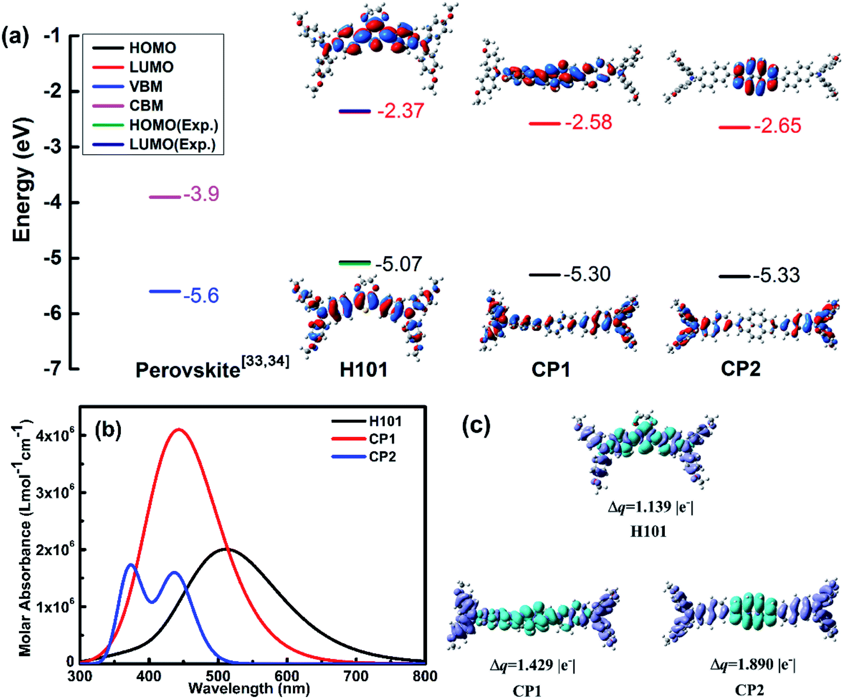 | ||
| Fig. 2 (a) Energy levels and frontier molecular orbitals of H101, CP1 and CP2 at the B3P86/6-311G(d,p) levels; (b) simulated absorption spectra of molecules H101, CP1 and CP2 using the TD-BMK/6-31g(d) functional and basis set in dichloromethane solution; (c) electron density difference plots of electronic transition for H101, CP1 and CP2 (isovalue: 4 × 10⁻² e au−3), Δq is transferred charge amount in |e−|. | ||
The optical properties of H101, CP1 and CP2 were calculated by TD-BMK/6-31g(d) in dichloromethane solution. The simulated absorption spectra of H101, CP1 and CP2 are presented in Fig. 2(b). The optical parameters of absorption and emission are listed in Table 1. As presented in Table 1 and Fig. 2(b), the absorption peak of H101 in dichloromethane solution is 398 nm from TD-BMK/6-31g(d) in according with that of experimental result (400 nm) in the same solution.35 Therefore, simulation on optical properties based on TD-BMK/6-31g(d) in dichloromethane solution is an effective way to obtain the optical properties of molecules H101, CP1 and CP2. The maximum absorption of H101 and CP1 in the S0–S1 states is mainly from the HOMO to LUMO transitions. Moreover, for CP2, the absorption is generated mainly from the HOMO to LUMO+1 transition, as evidenced by its maximum absorption in the S0–S2 states. As illustrated in Fig. 2(b) and Table 1, the maximum absorption wavelengths of H101, CP1 and CP2 at 398 nm, 372 nm and 365 nm, respectively, while the corresponding oscillator strength are 1.81, 2.10 and 1.94, respectively. The emission wavelength λem values for molecules H101, CP1 and CP2 are 513 nm, 446 nm and 437 nm, respectively. Therefore, the Stokes shifts of H101, CP1 and CP2 are 115 nm, 74 nm and 72 nm, respectively.
The electron density difference (EDD) plots can reflect the electron density distribution of H101, CP1 and CP2. As shown in Fig. 2(c), for H101, CP1 and CP2, the blue region is restricted to the π-bridge units in these molecules, which reflects the increasing in electron density, while the decreasing in electron density is distributed throughout the chains of H101, CP1 and CP2, which is represented by the purple part. The transfer charge (Δq) values of H101, CP1 and CP2 are 1.139, 1.429 and 1.890 |e−|, respectively. The results show that CP1 and CP2 have larger Δq than H101, which facilitates charge separation and thus can promote the performance of HTM in PSC applications.
When HTMs have good solubility, they can obtain a thicker film with spin-coating in PSC devices. The solubility of these HTMs are theoretically estimated by the solvation free energy (ΔG).37,38 In this paper, chlorobenzene was chosen as the solvent for the calculation of ΔG, which describes the difference between the free energy of the organic materials in the solvent and the gas.34,37 The calculated ΔG values of H101, CP1 and CP2 are −14.54, −11.72 and −12.95 kcal mol−1, respectively (Table 2). The ΔG values CP1 and CP2 are small than that of H101.
| IPa | EAa | η | ΔG | |
|---|---|---|---|---|
| H101 | 5.22 | 0.17 | 2.52 | −14.54 |
| CP1 | 5.60 | 0.34 | 2.63 | −11.72 |
| CP2 | 5.61 | 0.28 | 2.67 | −12.95 |
To ensure the normal application of PSC devices, the good stability of HTMs is required. The stability can be estimated by calculating the absolute hardness (η) of the HTMs (H101, CP1 and CP2). As shown in Table 2, calculation on the values of η for H101, CP1 and CP2 can be obtain from the equation, η = (IP − EA)/2, which are 2.52, 2.63 and 2.67 eV, respectively.39,40 The values of η for the CP1 and CP2 are over that of H101 (2.52 eV). It means that these HTMs of CP1 and CP2 may have good stability.
Hole transport properties of HTMs are extremely crucial parameters that affect the performance of PSC devices. In theory, the charge transport rate of organic electronic materials is evaluated using Marcus theory.41 The detailed description of Marcus theory was presented in ESI.† It is known that the recombination energy (λ) and the hole transfer integral (v) are the key parameters to determine the kh. In term of Marcus theory in eqn (S1),† a large v and a small λ is always to obtain a higher charge-transfer rate. The λh values for H101, CP1 and CP2 are 0.596, 0.115 and 0.114 eV, respectively. Both the designed CP1 and CP2 have a smaller λh than the parent H101 and may obtain a larger kh or hole mobility (uh) (see Table 3). The result of the reduced recombination energy of CP1 and CP2 can be explained by introducing the π-bridge groups with higher conjugated unit in HTMs than that of H101. Thus, the change in molecular structures of CP1 and CP2 was reduced when electron transfer occurs between adjacent molecules. In addition, the charge-transfer rate is also affected by another parameter of v. For the v, it strongly depends on the electron coupling strength of adjacent molecules.42 In order to obtain the main hole transfer pathways, the crystal structure of H101, CP1 and CP2 are predicted from the Material Studio software.43 The details of these calculations are written in the ESI.† For H101, CP1 and CP2, the crystal structures with the lowest total energy were presented in Fig. S2.† The predicted crystal data are listed in Table S2.† Table S2† indicated that the predicted results of the crystal structures for H101, CP1 and CP2 are P212121, P1 and P21 space group, respectively.
| HTMs | Pathways | λh | vh | kh | D | uh | uh(exp.)a |
|---|---|---|---|---|---|---|---|
| a Experimental value from ref. 35. | |||||||
| H101 | 1 | 0.596 | 2.895 × 10⁻³ | 5.71 × 10⁸ | 10.163 | 7.01 × 10⁻⁵ | 6.57 × 10⁻⁵ |
| 2 | −9.610 × 10⁻⁴ | 6.29 × 10⁷ | 11.265 | ||||
| 3 | −8.031 × 10⁻³ | 4.39 × 10⁹ | 5.170 | ||||
| 4 | 2.551 × 10⁻⁴ | 4.43 × 10⁶ | 23.995 | ||||
| 5 | −3.171 × 10⁻⁶ | 6.85 × 10² | 23.930 | ||||
| 6 | −1.051 × 10⁻⁴ | 7.53 × 10⁵ | 23.283 | ||||
| 7 | 6.350 × 10⁻⁵ | 2.75 × 10⁵ | 23.559 | ||||
| 8 | −8.471 × 10⁻⁵ | 4.89 × 10⁵ | 23.493 | ||||
| 9 | −9.710 × 10⁻⁴ | 6.42 × 10⁷ | 11.265 | ||||
| CP1 | 1 | 0.115 | 6.749 × 10⁻⁵ | 7.39 × 10⁷ | 7.937 | 2.98 × 10⁻² | |
| 2 | 1.534 × 10⁻⁴ | 1.22 × 10⁷ | 18.324 | ||||
| 3 | −2.745 × 10⁻⁵ | 3.82 × 10⁸ | 13.291 | ||||
| 4 | 4.062 × 10⁻⁴ | 8.66 × 10¹¹ | 11.062 | ||||
| 5 | −1.705 × 10⁻² | 2.68 × 10⁹ | 11.180 | ||||
| 6 | −7.308 × 10⁻³ | 9.02 × 10⁸ | 21.435 | ||||
| 7 | 2.358 × 10⁻⁴ | 1.04 × 10¹⁰ | 16.907 | ||||
| 8 | −8.006 × 10⁻⁴ | 1.55 × 10⁸ | 11.750 | ||||
| CP2 | 1 | 0.114 | 1.218 × 10⁻³ | 2.44 × 10¹⁰ | 10.714 | 4.18 × 10⁻³ | |
| 2 | 3.000 × 10⁻⁵ | 1.48 × 10⁷ | 21.637 | ||||
| 3 | −1.502 × 10⁻³ | 3.71 × 10¹⁰ | 15.447 | ||||
According to the predicted crystal structure, the main hole-hopping pathways of H101, CP1 and CP2 are obtained and presented in Fig. 3. On basis of the parameters of hole recombination energy (λh) and the transfer integral (vh), the hole-transfer rate (kh) and hole mobility (uh) of HTMs molecules can be calculated by the Marcus equation and Einstein relation, respectively.41 According to Fig. 3 and Table 3, the predicted uh of H101 (7.01 × 10⁻⁵ cm2 V−1 s−1) agrees well with the experimental value (6.57 × 10⁻⁵ cm2 V−1 s−1).35 This result can support the reliability of the theoretical model for calculating the hole mobility of HTMs in this work. The uh values of the designed CP1 and CP2 are 2.98 × 10⁻² and 4.18 × 10⁻³ cm2 V−1 s−1, respectively (Table 3). In comparison with H101, the larger hole mobility values of CP1 and CP2 are attributed to the larger transfer integral and smaller recombination energy. It is also for this reason that the introduction of conjugated π-bridge units should be an efficient method to obtain promising HTMs with high hole mobility. This may improve the performance of CP1 and CP2 as HTM in PSC applications.
 | ||
| Fig. 3 Main hole hopping pathways selected on basis of the crystal structures for H101, CP1 and CP2. | ||
The results indicated that the designed CP1 and CP2 with suitable frontier molecular orbital energy are in good matching with the valence band and conduction band of CsFAMA. In comparison with H101, the designed CP1 and CP2 exhibit better performance such as better stability, good solubility and higher hole mobility. The designed CP1 and CP2 with the high hole mobility (2.98 × 10⁻² and 4.18 × 10⁻³ cm2 V−1 s−1) may act as promising HTMs in PSC applications. To achieve a goal that verifies the computational method for the material design of the alternative HTMs, the potential CP1 and CP2 as the target was further synthesized and used it as an HTM to explore its performance in PSC devices.
2.2 Synthesis and material characterization
As shown in Fig. 4(a), CP1 and CP2 were synthesized by one-step Suzuki reaction cross-coupling. Molecules CP1 and CP2 can be synthesized based on previous reports for route rationalization.17,44 The detailed synthesis of CP1 and CP2 is given in the SI. CP1 and CP2 was characterized by 1H NMR, 13C NMR and high-resolution mass spectrometry (HR-MS) shown in Fig. S3–S8.† Materials of CP1 and CP2 can be dissolved in common solvents, such as chlorobenzene, tetrahydrofuran, ethyl acetate, dichloromethane, etc.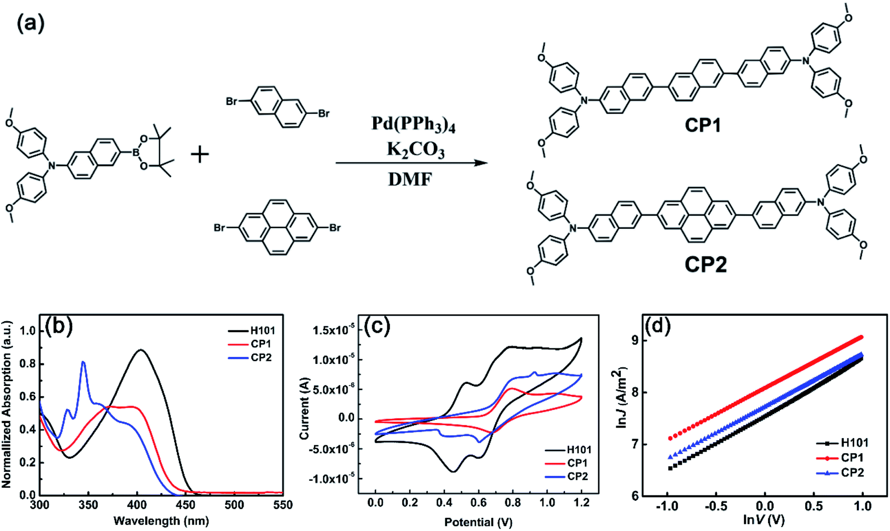 | ||
| Fig. 4 (a) Synthesis process of CP1 and CP2. (b) Normalized absorption spectra of H101, CP1 and CP2 in dichloromethane. (c) Cyclic voltammetry of H101, CP1 and CP2 in dichloromethane solution. (d) Space-charge-limited current (SCLC) J–V characteristics of H101, CP1 and CP2 based hole-only devices. | ||
The UV-vis absorption spectra of H101 CP1 and CP2 have been investigated in dichloromethane solution. Normalized absorption spectra and corresponding parameters of H101, CP1 and CP2 are presented in Fig. 4(b) and Table 4, respectively. As shown in Fig. 4(b) and Table 4, the maximum absorption peaks and absorption onset (in parentheses) of H101, CP1 and CP2 were 404 (450), 372 (433) and 344 (429) nm, corresponding to optical energy gaps (Eg) of 2.75, 2.86 and 2.89 eV, respectively. The calculated parameters of UV spectra for HTMs are consistent with the experimental values. As shown in Tables 1 and 4, the maximum absorption of CP1 in dichloromethane solution (372 nm) was compared with the calculated value (372 nm) is in general agreement, and the same is true for CP2.
| HTM | λmaxa | Egb | λonset | HOMO | LUMOc | Hole mobilityd |
|---|---|---|---|---|---|---|
| a Absorption spectra were measured in dichloromethane solution.b Optical band gap (Eg) obtained from the onset values of absorption (λonset).c LUMO = HOMO + Eg.d Hole mobility was measured by using the space-charge-limited current (SCLCs) method (ITO/PEDOT:PSS/HTM/MoO3/Ag). | ||||||
| H101 | 404 | 2.75 | 450 | −5.10 | −2.35 | 9.54 × 10⁻⁵ |
| CP1 | 372 | 2.86 | 433 | −5.33 | −2.47 | 1.46 × 10⁻⁴ |
| CP2 | 344 | 2.89 | 429 | −5.37 | −2.48 | 1.20 × 10⁻⁴ |
To investigate the frontier molecular orbital information of HTMs (H101, CP1 and CP2), cyclic voltammetry (CV) tests were performed. As shown in Fig. 4(c) and Table 4, CV measurements indicate that the HOMO levels of H101, CP1 and CP2 are −5.10 eV, −5.33 eV and −5.37 eV, respectively. The experimental values of the LUMO energy levels for H101, CP1 and CP2 are −2.35 eV, −2.47 eV and −2.48 eV, respectively. In addition, the energy values of the HOMO for CP1 and CP2 on the theoretical simulations are −5.30 and −5.33 eV, respectively. Since the VB of CsFAMA in the PSC device (−5.6 eV) is lower than the HOMO energy levels of CP1 and CP2, this indicates that the HOMO of CP1 and CP2 matches the VB of CsFAMA. The energy level of LUMO is higher than the CB of CsFAMA (−3.9 eV), which can effectively prevent the electron transfer from CsFAMA to the metal electrode.
In the theoretical calculation section, the hole mobilities of H101, CP1 and CP2 have been simulated and obtained as 7.01 × 10⁻⁵, 2.98 × 10⁻² and 4.18 × 10⁻³ cm2 V−1 s−1, respectively (see Table 3). To verify the accuracy of the results, the current–voltage (J–V) response was measured by the space charge-limited current (SCLC) method by using ITO/PEDOT:PSS/HTM/MoO3/Ag devices under dark conditions. The results as follows (see Fig. 4(d) and Table 4) indicate that the hole mobilities of both CP1 (1.46 × 10⁻⁴ cm2 V−1 s−1) and CP2 (1.20 × 10⁻⁴ cm2 V−1 s−1) are higher than that of the parent H101 (9.54 × 10⁻⁵ cm2 V−1 s−1), which is consistent with the trend of the theoretical calculation results. However, compared with the calculated results of hole mobility for CP1 and CP2, the smaller experimental values of hole mobility are mainly influenced by that the calculated values are based on the crystal structure, while the experimental values are based on the amorphous film.41
Based on the above analysis, in PSC applications, CP1 and CP2 may be more promising than H101. Hence, we fabricated devices with structure FTO-TiO2/CSFAMA/HTMs/Ag to study the performance of CP1 and CP2 in PSC devices (see Fig. 5(a)).
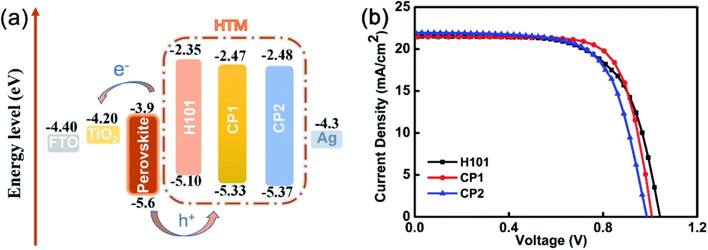 | ||
| Fig. 5 (a) Energy level diagram of H101, CP1 and CP2 in PSCs. (b) J–V curves of PSCs based on H101, CP1 and CP2. | ||
2.3 Photovoltaic performance
On basis of H101, CP1 and CP2 as HTMs, the photovoltaic properties of PSC devices were investigated. The device configuration of FTO-TiO2/CSFAMA/HTMs/Ag were fabricated. CsFAMA is an ion-mixed perovskite active layer (FAPbI3)0.875(MAPbBr3)0.075(CsPbI3)0.05(PbI2)0.03, which was reported by Wang and co-workers.34 The current density–voltage (J–V) curves of the best devices for H101, CP1 and CP2 as HTMs are presented in Fig. 5(b). The corresponding photovoltaic parameters are listed in Table 5. As shown in Table 5, the J–V curves were measured at 100 mW cm−2 (AM 1.5 G) under simulated sunlight and yielded a PCE of 15.91%, Jsc of 21.45 mA cm−2, Voc of 1.007 V, and FF of 73.61% for the best CP1-based PSC device. Meanwhile, the best CP2-based PSC device exhibited a PCE of 14.68%, Jsc of 21.96 mA cm−2, Voc of 0.986 V, and FF of 67.83%. Under the same conditions, the H101-based PSC device exhibited a PCE of 14.78%, Jsc of 21.53 mA cm−2, Voc of 1.042 V and FF of 65.87%. Obviously, the CP1-based device possesses better FF because of the better hole transporting ability. The CP1-based device also possesses a performance that is not inferior to that of the H101-based device, and the actual performance trend of the PSCs is consistent with the hole mobilities previously obtained based on these three HTMs. However, the CP2-based device with smaller PCE than H101 and CP1 may be attribute to its poor film-formation.| HTM | Jsc [mA cm−2] | Voc [V] | FF [%] | PCE [%] |
|---|---|---|---|---|
| a The maximum value.b The average value were obtained from 12 devices. | ||||
| H101 | 21.53(21.49 ± 0.12) | 1.042(1.018 ± 0.018) | 65.87(64.40 ± 1.97) | 14.78a(14.08 ± 0.39)b |
| CP1 | 21.45(21.24 ± 0.21) | 1.007(1.004 ± 0.006) | 73.61(73.44 ± 0.59) | 15.91(15.66 ± 0.18) |
| CP2 | 21.96(21.40 ± 0.96) | 0.986(0.977 ± 0.015) | 67.83(65.99 ± 3.30) | 14.68(13.79 ± 0.82) |
In addition, we also performed the forward and reverse voltage scans (Fig. S9 and Table S3†) for the devices at the optimal devices for H101, CP1 and CP2 as HTMs. HI = [PCE (forward) − PCE (reverse)]/PCE (forward) is the equation for the hysteresis index (HI).46 The hysteresis of both H101, CP1 and CP2 devices are correlated with defects, ion migration, ferroelectric polarization.45 The box charts of photovoltaic parameters (Fig. S10†) and statistical parameters (Table 5) based on 12 identical devices were used to explore the PCE test reproducibility of PSC devices based on HTMs (H101, CP1 and CP2). The results show that both H101, CP1 and CP2 have excellent reproducibility in PSC devices. In addition, stability tests were performed with CP1 as unencapsulated PSCs under N2 conditions, and the results showed that the devices have good stability (see Fig. S11†).
2.4 Hole extraction and charge recombination at interfaces
The film-forming property of HTMs may have a significant impact on the performance of PSC devices. The film morphologies of the H101, CP1 and CP2 were investigated by the atomic force microscopy (AFM), and the topographic AFM images of H101, CP1 and CP2 capping on the perovskite layers are shown in Fig. 6(a)–(d). The root mean square (RMS) roughness of the perovskite layer is 20.9 nm, and the RMS value is significantly reduced after spin-coating H101, CP1 and CP2. After coating H101, CP1 and CP2 on the perovskite layer, their RMS roughness was 14.8 nm, 13.3 nm and 16.4 nm, respectively. All HTMs films showed a significant decrease in RMS roughness after rotational coating, which indicates a much better interface between the HTMs films (H101, CP1 and CP2) and the perovskite layer. The RMS roughness of CP1 film is significantly lower than that of H101 and CP2 films. Therefore, the film of CP1 in PSC device can provide the good charge transfer from the perovskite to HTM and the reducing recombination loss, which leads to an ultimately increased FF. | ||
| Fig. 6 (a–d) AFM image of perovskite film without or with capping different HTMs of H101, CP1 and CP2. (e) Steady-state PL spectra of the perovskite films with and without HTMs. (f) Time-resolved PL decay of pristine perovskite film and perovskite/HTM films (H101, CP1 and CP2). | ||
Steady-state photoluminescence (PL) spectroscopy is an efficient way to investigate the hole extraction on the perovskite/HTMs interface. As shown in Fig. 6(e) and (f), the film of perovskite has a strong PL peak of 775 nm. When H101, CP1 and CP2 are coated on the perovskite film, PL intensity is quenched obviously. The results show that the holes at the interface between perovskite and HTMs have been extracted effectively. Specially, the CP1 and CP2 can yield a slightly higher PL quenching efficiency compared to H101, which confirms that CP1 and CP2 have strong hole-extraction capability in PSCs, can transfer holes from perovskite to HTMs (CP1 or CP2) more effectively. The hole extraction efficiencies at perovskite/HTMs interfaces have been exploded by time-resolved photoluminescence (TRPL) measurement. As presented in Fig. 6(f), the original perovskite film exhibits a long PL decay, which is strongly inhibited when the perovskite layer is in contact with HTM. The PL decay lifetimes for the H101, CP1 and CP2 film on the perovskite film are significantly shorter than the perovskite film. Especially, the PL decay lifetimes for CP1 and CP2 film on the perovskite film are shorter than that of H101. The results illustrate that CP1 and CP2 may exhibits comparable hole-extracting ability to H101.
3. Conclusions
In this study, on basis of the provided computational model, two N,N-bis(4-methoxyphenyl)naphthalen-2-amine derivative-based HTMs (CP1 and CP2) were investigated by DFT and TD-DFT combined with Marcus theory. The calculated result indicated that the designed CP1 and CP2 with better properties such as good stability, high hole mobility and good solubility compared with the parent H101. Further, we have synthesized the promising HTMs (CP1 and CP2) and applied them to PSC devices in order to verify the feasibility of the calculation model. Among them, CP1 shows more excellent performance, and the PSC device (CP1-based) exhibits a superior PCE (15.91%) in comparison with that of the H101-based PSC device (14.78%). This work proves out that the strategy of modulation on conjugated π-bridge cores in N,N-bis(4-methoxyphenyl)naphthalen-2-amine derivative-based HTMs with donor–π–donor configuration is feasible. Moreover, the experimental data can reproduce the theoretical results very well, indicating that the provided model of molecular design is a feasible way to obtain the alternative N,N-bis(4-methoxyphenyl)naphthalen-2-amine derivative-based HTMs.Conflicts of interest
There are no conflicts to declare.Acknowledgements
This work was supported by National Training Program of Innovation and Entrepreneurship for Undergraduates (Grant No. 202010635107), National Natural Science Foundation of China (Grant No. 21803043), Natural Science Foundation of Chongqing (Grant No. cstc2020jcyj-msxmX0379), and Fundamental Research Funds for the Central Universities (Grant No. SWU117050).References
- H. D. Pham, T. C.-J. Yang, S. M. Jain, G. J. Wilson and P. Sonar, Adv. Energy Mater., 2020, 10, 1903326 CrossRef CAS.
- N. Drigo, C. Roldan-Carmona, M. Franckevicius, K.-H. Lin, R. Gegevicius, H. Kim, P. A. Schouwink, A. A. Sutanto, S. Olthof, M. Sohail, K. Meerholz, V. Gulbinas, C. Corminboeuf, S. Paek and M. K. Nazeeruddin, J. Am. Chem. Soc., 2020, 142, 1792–1800 CrossRef CAS PubMed.
- M. Habibi, F. Zabihi, M. R. Ahmadian-Yazdi and M. Eslamian, Renewable Sustainable Energy Rev., 2016, 62, 1012–1031 CrossRef CAS.
- W. Z. Li, J. D. Fan, J. W. Li, Y. H. Mai and L. D. Wang, J. Am. Chem. Soc., 2015, 137, 10399–10405 CrossRef CAS PubMed.
- G. W. Kim, H. Choi, M. Kim, J. Lee, S. Y. Son and T. Park, Adv. Energy Mater., 2020, 10, 1903403 CrossRef CAS.
- L. Mazzarella, Y. H. Lin, S. Kirner, A. B. Morales-Vilches, L. Korte, S. Albrecht, E. Crossland, B. Stannowski, C. Case, H. J. Snaith and R. Schlatmann, Adv. Energy Mater., 2019, 9, 1803241 CrossRef.
- T. Niu, W. Zhu, Y. Zhang, Q. Xue, X. Jiao, Z. Wang, Y.-M. Xie, P. Li, R. Chen, F. Huang, Y. Li, H.-L. Yip and Y. Cao, Joule, 2021, 5, 249–269 CrossRef CAS.
- Z. Wu, C. Sun, S. Dong, X. F. Jiang, S. Wu, H. Wu, H. L. Yip, F. Huang and Y. Cao, J. Am. Chem. Soc., 2016, 138, 2004–2013 CrossRef CAS PubMed.
- Z. Yu, A. Hagfeldt and L. Sun, Coord. Chem. Rev., 2020, 406, 213143 CrossRef CAS.
- G. Ren, W. Han, Y. Deng, W. Wu, Z. Li, J. Guo, H. Bao, C. Liu and W. Guo, J. Mater. Chem. A, 2021, 9, 4589–4625 RSC.
- L. Zhang, X. Zhou, C. Liu, X. Wang and B. Xu, Small Methods, 2020, 4, 2000254 CrossRef CAS.
- A. Y. Mei, X. Li, L. F. Liu, Z. L. Ku, T. F. Liu, Y. G. Rong, M. Xu, M. Hu, J. Z. Chen, Y. Yang, M. Gratzel and H. W. Han, Science, 2014, 345, 295–298 CrossRef CAS PubMed.
- S. S. Reddy, K. Gunasekar, J. H. Heo, S. H. Im, C. S. Kim, D. H. Kim, J. H. Moon, J. Y. Lee, M. Song and S. H. Jin, Adv. Mater., 2016, 28, 686–693 CrossRef CAS PubMed.
- K. Rakstys, C. Igci and M. K. Nazeeruddin, Chem. Sci., 2019, 10, 6748–6769 RSC.
- X. D. Guo, G. D. Niu and L. D. Wang, Acta Chim. Sin., 2015, 73, 211–218 CrossRef CAS.
- M. Saliba, S. Orlandi, T. Matsui, S. Aghazada, M. Cavazzini, J.-P. Correa-Baena, P. Gao, R. Scopelliti, E. Mosconi, K.-H. Dahmen, F. De Angelis, A. Abate, A. Hagfeldt, G. Pozzi, M. Graetzel and M. K. Nazeeruddin, Nat. Energy, 2016, 1, 15017 CrossRef CAS.
- W. Chen, T. Liu, X. Sun, F. Guo, Y. Wang, C. Shi, R. Ghadari and F. Kong, J. Power Sources, 2019, 425, 87–93 CrossRef CAS.
- M. Hao, W. Chi and Z. Li, Nanoscale, 2021, 13, 4241–4248 RSC.
- H. Ashassi-Sorkhabi, P. Salehi-Abar and A. Kazempour, Sol. Energy, 2019, 180, 146–151 CrossRef CAS.
- M. Hao, W. Chi and Z. Li, Chem.–Asian J., 2020, 15, 287–293 CrossRef CAS PubMed.
- Z.-Z. Sun, S. Feng, W.-L. Ding, X.-L. Peng, J.-L. Liu and X.-L. Xu, Sol. Energy, 2021, 224, 491–499 CrossRef CAS.
- K. Wang, Q. Wang, X. Chen and G. Ji, Sol. Energy, 2021, 217, 93–104 CrossRef CAS.
- X. Chen, H. Sakurai and H. Wang, et al., Theoretical study on the molecular stacking interactions and charge transport properties of triazasumanene crystals – from explanation to prediction, Phys. Chem. Chem. Phys., 2021, 23(8), 4681–4689 RSC.
- X. Chen, H. Wang and B. Wang, et al., Charge transport properties in organic D-A mixed-stack complexes based on corannulene and sumanene derivatives-a theoretical study, Org. Electron., 2019, 68, 35–44 CrossRef CAS.
- X. Chen, F.-Q. Bai and H.-T. Wang, et al., The impact of molecular stacking interactions on the electronic structure and charge transport properties in distyrylbenzene (DSB-) based D–A complexes: a theoretical study, RSC Adv., 2015, 5(59), 47681–47691 RSC.
- S.-P. Wang, Y. Wang and F.-Y. Chen, et al., Accurate Analysis of Anisotropic Carrier Mobility and Structure–property Relationships in Organic BOXD Crystalline Materials, Front. Chem., 2021, 9, 882 Search PubMed.
- X. Liu and X. Liu, RSC Adv., 2019, 9, 24733–24741 RSC.
- Q. Chen, P. Cheng, H. Liu and X. Liu, Sustainable Energy Fuels, 2021, 5, 3403–3413 RSC.
- J. Qiu, H. Liu, X. Li and S. Wang, Chem. Eng. J., 2020, 387, 123965 CrossRef CAS.
- H. Li, K. Fu, A. Hagfeldt, M. Gratzel, S. G. Mhaisalkar and A. C. Grimsdale, Angew. Chem., Int. Ed., 2014, 53, 4085–4088 CrossRef CAS PubMed.
- Q. Xiao, F. Wu, M. Han, Z. Li, L. Zhu and Z. a. Li, J. Mater. Chem. A, 2018, 6, 13644–13651 RSC.
- K. Jiang, F. Wu, H. Yu, Y. Yao, G. Zhang, L. Zhu and H. Yan, J. Mater. Chem. A, 2018, 6, 16868–16873 RSC.
- F. Li, Z. Shen, Y. Weng, Q. Lou, C. Chen, L. Shen, W. Guo and G. Li, Adv. Funct. Mater., 2020, 30, 2004933 CrossRef CAS.
- H. Yao, T. Wu, B. Wu, H. Zhang, Z. Wang, Z. Sun, S. Xue, Y. Hua and M. Liang, J. Mater. Chem. A, 2021, 9, 8598–8606 RSC.
- P.-Y. Su, Y.-F. Chen, J.-M. Liu, L.-M. Xiao, D.-B. Kuang, M. Mayor and C.-Y. Su, Electrochim. Acta, 2016, 209, 529–540 CrossRef CAS.
- P. Hong Duc, H. Hu, F.-L. Wong, C.-S. Lee, W.-C. Chen, K. Feron, S. Manzhos, H. Wang, N. Motta, Y. M. Lam and P. Sonar, J. Mater. Chem. C, 2018, 6, 9017–9029 RSC.
- J. Ho, A. Klamt and M. L. Coote, J. Phys. Chem. A, 2010, 114, 13442–13444 CrossRef CAS PubMed.
- Y. Zhang, Y. Li, C. Chen, L. Wang and J. Zhang, Org. Electron., 2017, 49, 255–261 CrossRef CAS.
- W.-J. Chi, Q.-S. Li and Z.-S. Li, Nanoscale, 2016, 8, 6146–6154 RSC.
- H. Liu and X. Liu, J. Mater. Chem. C, 2018, 6, 6816–6822 RSC.
- W.-Q. Deng, L. Sun, J.-D. Huang, S. Chai, S.-H. Wen and K.-L. Han, Nat. Protoc., 2015, 10, 632–642 CrossRef CAS PubMed.
- A. Zhugayevych, O. Postupna, R. C. Bakus II, G. C. Welch, G. C. Bazan and S. Tretiak, J. Phys. Chem. C, 2013, 117, 4920–4930 CrossRef CAS.
- G. M. Day, W. D. S. Motherwell, H. L. Ammon, S. X. M. Boerrigter, R. G. Della Valle, E. Venuti, A. Dzyabchenko, J. D. Dunitz, B. Schweizer, B. P. van Eijck, P. Erk, J. C. Facelli, V. E. Bazterra, M. B. Ferraro, D. W. M. Hofmann, F. J. J. Leusen, C. Liang, C. C. Pantelides, P. G. Karamertzanis, S. L. Price, T. C. Lewis, H. Nowell, A. Torrisi, H. A. Scheraga, Y. A. Arnautova, M. U. Schmidt and P. Verwer, Acta Crystallogr., Sect. B: Struct. Sci., Cryst. Eng. Mater., 2005, 61, 511–527 CrossRef CAS PubMed.
- X. Liu, F. Kong, F. Guo, T. Cheng, W. Chen, T. Yu, J. Chen, Z. a. Tan and S. Dai, Dyes Pigm., 2017, 139, 129–135 CrossRef CAS.
- D. Shi, X. Qin, Y. Li, Y. He, C. Zhong, J. Pan, H. Dong, W. Xu, T. Li, W. Hu, J.-L. Bredas and O. M. Bakr, Sci. Adv., 2016, 2, e1501491 CrossRef PubMed.
- X. Yu, Z. Li, X. Sun, C. Zhong, Z. Zhu, Z. a. Li and A. K. Y. Jen, Nano Energy, 2021, 82, 105701 CrossRef CAS.
Footnotes |
| † Electronic supplementary information (ESI) available. See DOI: 10.1039/d1ra08133k |
| ‡ The authors contribute equally to this work. |
| This journal is © The Royal Society of Chemistry 2022 |