DOI:
10.1039/D1RA08062H
(Paper)
RSC Adv., 2022,
12, 420-428
Luminescence properties, energy transfer and thermal stability of white emitting phosphor Sr3(PO4)2:Ce3+/Tb3+/Mn2+ for white LEDs
Received
3rd November 2021
, Accepted 15th December 2021
First published on 21st December 2021
Abstract
A series of Sr3(PO4)2:Ce3+/Mn2+/Tb3+ phosphors were synthesized by a high temperature solid phase method. After introducing Ce3+ as sensitizer in Sr3(PO4)2:Ce3+/Mn2+, the efficient energy transfer from Ce3+ to Mn2+ was observed and analyzed in detail, and Sr3(PO4)2:Ce3+/Mn2+ was demonstrated to be color tunable, changing from blue to orange red. In addition, Tb3+ ion, which mainly emits green light, was further added into the Sr3(PO4)2:Ce3+/Mn2+. Due to the addition of this green emission, the white emitting phosphors with good quality were obtained. At the same time, the energy transfer mechanisms among Ce3+, Tb3+ and Mn2+ ions were also analyzed in detail. The results show that Sr3(PO4)2:Ce3+/Mn2+/Tb3+ is a promising candidate for white light emitting diodes.
1 Introduction
In recent years, solid-state light sources have been widely used because of their advantages such as long lifetime, high emitting intensity, excellent conversion efficiency and environmental friendliness. In order to better meet the demand of applications, it is essential to obtain phosphors with adjustable emission bands.1–5 Typically, the tuning-color can be achieved via energy transfer from sensitizer to activator, such as Ce3+–Tb3+, Ce3+–Mn2+, Tb3+–Mn2+ or Eu2+–Mn2+.6–10 Through matrix component regulation and cation substitution, the crystal field environment surrounding the luminescent centers can be changed, thus causing the tunable luminescence phenomenon.11–13 Phosphate has been widely studied in the field of optics because of its stable structure and excellent chemical properties.14,15 Sr3(PO4)2 (SPO) is a common and classical phosphate, which, however, has been less studied in the field of luminescent materials over past decades. In addition, only several kinds of activators have been briefly studied in the host of SPO. Therefore, it is necessary to investigate the luminescence features of typical luminescent centers in SPO. In this work, a series of Ce3+, Tb3+ and Mn2+ singly- or codoped SPO were synthesized, and the energy transfer can be observed from the codoped phosphors. The results show that these phosphors may be application in the white lighting diodes.
2 Sample preparation and characterization
2.1 Sample preparation
A series of SPO:xCe3+, SPO:xCe3+, zMn2+ and SPO:0.08Ce3+, yTb3+, 0.05Mn2+ were synthesized by the high temperature solid state method. The raw materials were SrCO3 (99.99%), MnCO3 (99.99%), Eu2O3 (99.99%), CeO2 (99.99%), NH4H2PO4 (99.99%) and Tb4O7 (99.99%). Firstly, the raw materials, according to the calculated chemical formula, were weighed and fully grinded by an agate mortar by 20 minutes to form uniform powder. Next, the mixture was loaded into corundum crucible and calcined at 960 °C for 300 min in air to achieve the final samples in the box-type furnace.
2.2 Characterization
The structure of sample was characterized by German Bruker D8 Xray diffractometer (Cu target Kα, λ = 0.15406 nm). The voltage and current are 40 kV and 40 mA, respectively. The scan range of 2θ degree and step size are 10–80° and 0.02°, respectively. The spectra of samples were measured by Horiba FL-4600 fluorescence spectrometer. The fluorescence lifetime of samples was measured by Horiba FL-1057 fluorescence spectrometer, and the excitation sources are nano-LED emitting at 335 nm and Xe lamp. The steady state transient fluorescence spectrometer of Horibafl-4600 was used to measure the fluorescence attenuation curve of the sample.
3 Results and discussion
3.1 Crystal structure
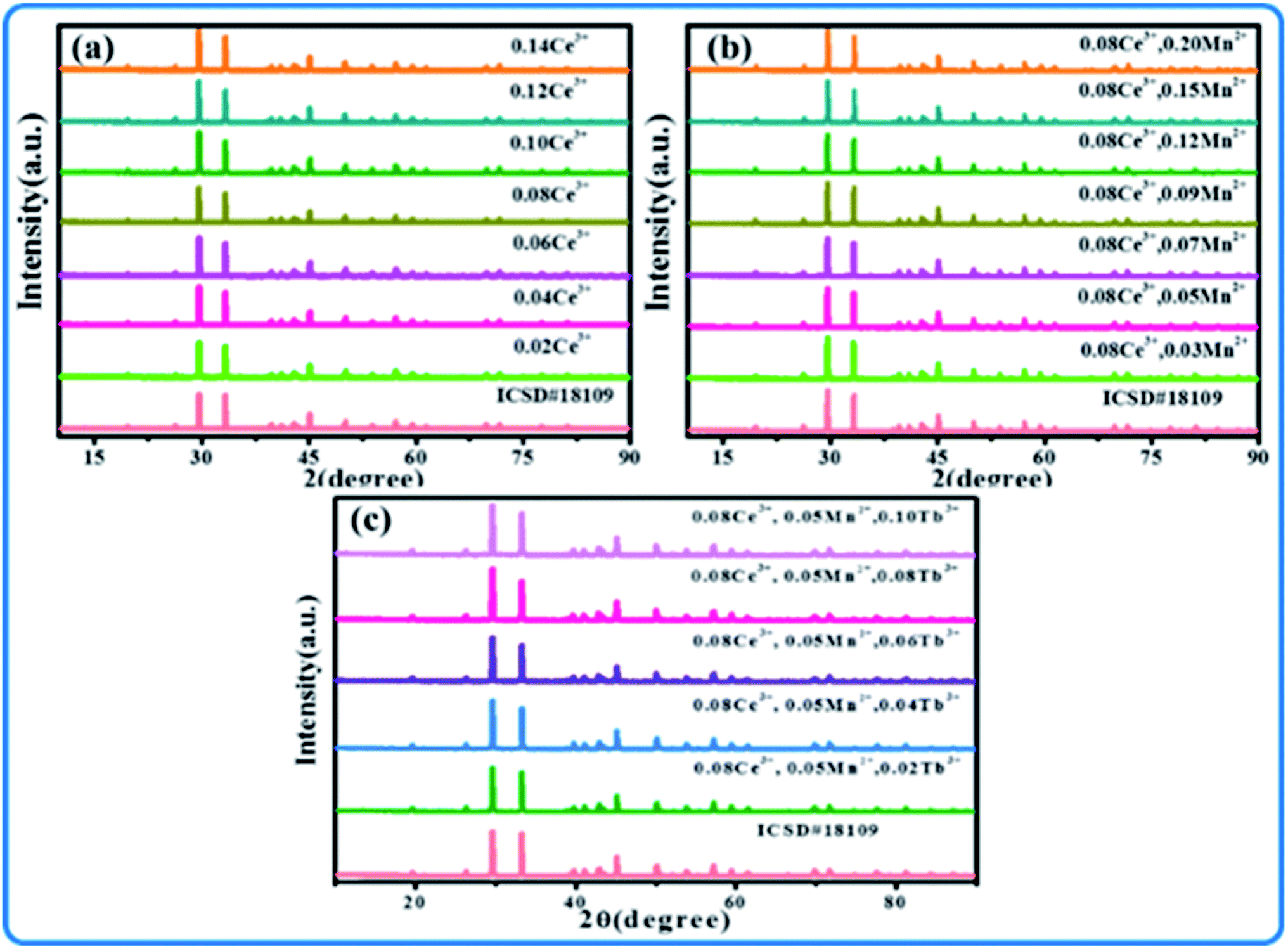
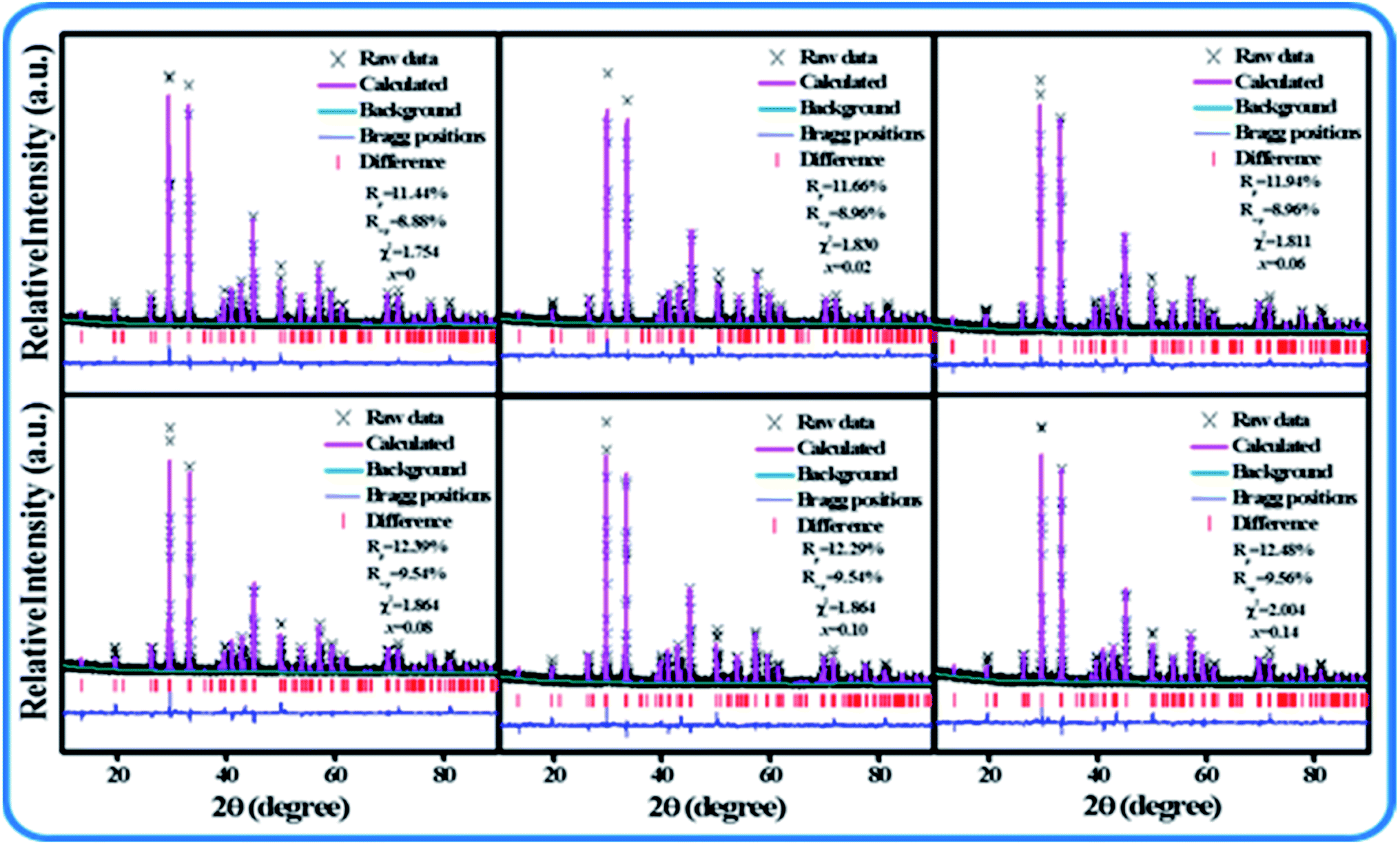
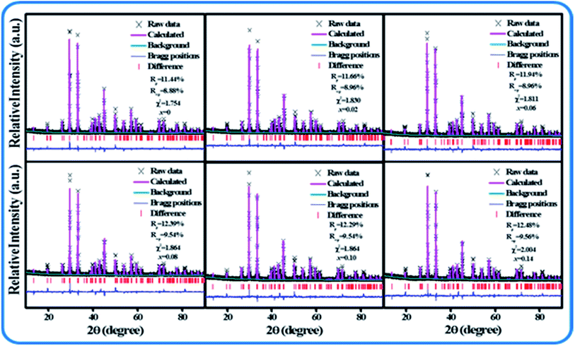
Fig. 1(a–c) show the XRD patterns of SPO:Ce3+, SPO:Ce3+, Mn2+ and SPO:0.08Ce3+, Tb3+, 0.05Mn2+, respectively. It can be seen that no redundancy diffraction peaks appeared for all samples, indicating that the as-synthesized samples are all of single crystal phase. The introduction of luminescent centers Ce3+, Tb3+ and Mn2+ has no influence on the crystal structure of SPO. In order to further inspect the minor change of SPO induced by Ce3+, Tb3+ and Mn2+, Rietveld refinement was performed on all samples, and the results are shown in Fig. 2, Tables 1 and 2. The parameters of Rp, Rwp and χ2 are all within the range of reliable values. According to the refined data presented in Table 1, as Ce3+ ions gradually entered into SPO, the volume V gradually increased. As is well known, if an ion with smaller radius enters into lattice site, the lattice volume is expected to shrink. However, as the number of Ce3+(r = 0.108 Å, N = 6; r = 0.125 Å, N = 10)ions gradually increased, the volume V gradually increased. The reason for this phenomenon is as follows there are some Ce3+ ions in the gap of lattice, which makes the volume V increase gradually.16,17
 |
| | Fig. 1 XRD patterns of (a) SPO:xCe3+, (b) SPO:0.08Ce3+, zMn2+, and (c) SPO:0.08Ce3+, yTb3+, 0.05Mn2+. | |
 |
| | Fig. 2 XRD refinement of SPO:xCe3+. | |
Table 1 Rietveld refinement results SPO:xCe3+
| SPO:xCe3 |
a = b = c |
V |
Rp |
Rwp |
χ2 |
| x = 0 |
7.2923 |
165.834 |
8.88% |
11.44% |
1.754 |
| x = 0.02 |
7.2929 |
166.842 |
8.96% |
11.66% |
1.830 |
| x = 0.06 |
7.2947 |
166.843 |
9.08% |
11.94% |
1.794 |
| x = 0.08 |
7.2942 |
166.869 |
9.56% |
12.39% |
1.967 |
| x = 0.10 |
7.2949 |
166.882 |
9.54% |
12.29% |
1.864 |
| x = 0.14 |
7.2958 |
165.899 |
9.56% |
12.48% |
2.004 |
Table 2 Bond length and twist degree of SPO:xCe3+
| SPO:xCe3+ |
0 |
0.02 |
0.06 |
0.08 |
0.10 |
0.14 |
| Sr1–O2 |
2.62392 |
2.62407 |
2.62431 |
2.62433 |
2.62456 |
2.62458 |
| Sr2–O1 |
2.47392 |
2.47397 |
2.47416 |
2.47429 |
2.47440 |
2.47445 |
| Sr2–O2 |
2.63424 |
2.63440 |
2.63464 |
2.63466 |
2.63489 |
2.63492 |
| Sr2–O2 |
2.72923 |
2.72916 |
2.72913 |
2.72902 |
2.72885 |
2.72855 |
| Distortion |
0.06483 |
0.06478 |
0.06456 |
0.06447 |
0.06442 |
0.06439 |
3.2 Luminescence characteristics of Sr3(PO4)2:Ce3+
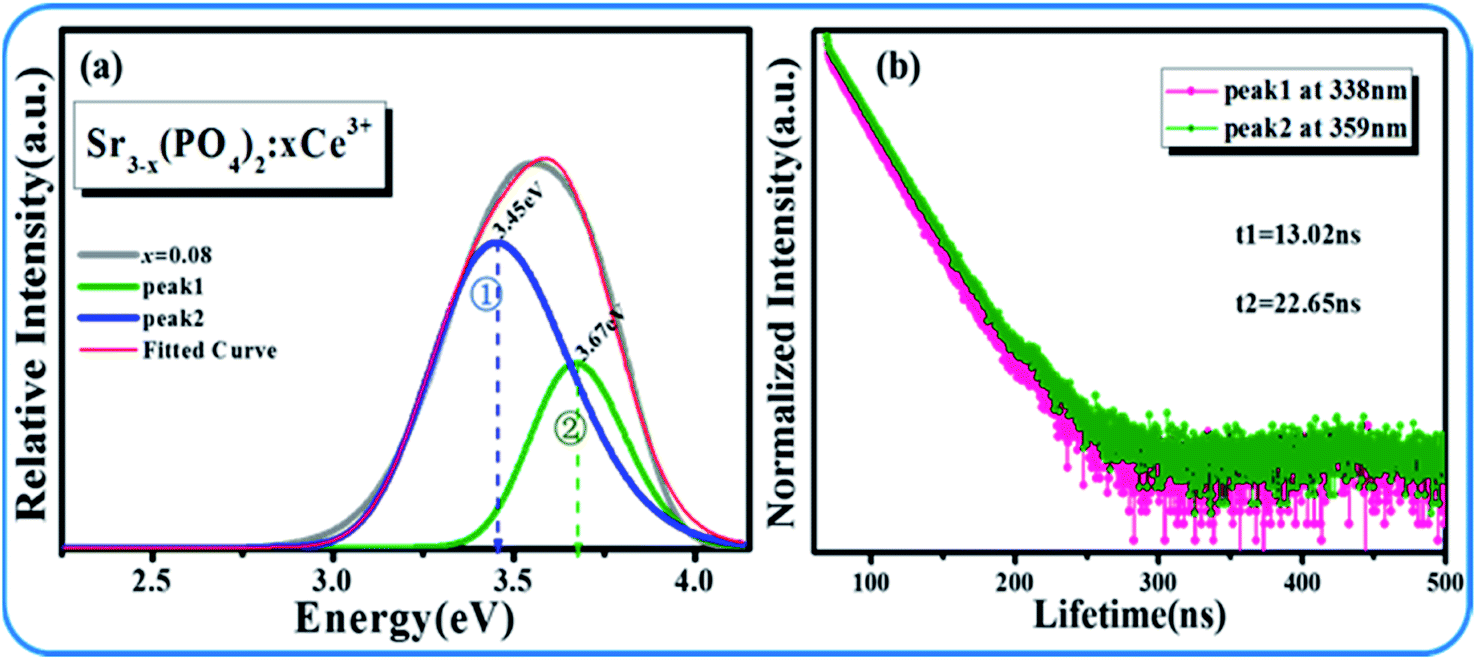
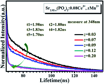
Fig. 3(a and b) display the emission and excitation spectra of SPO:xCe3+, respectively. The excitation band ranges from 240 to 320 nm with center wavelength at 292 nm. And the emission band is also a broad spectrum, which is located in the range of 300–450 nm and peaked at 348 nm. The optimal concentration of Ce3+ is 8% in molar ratio. In addition, it can be found that the emission band of Ce3+ is asymmetrical, which is composed of two sub-lines with peak at 338 and 359 nm, respectively (Fig. 4(a)). In order to determine the origin of these two sub-peaks, their decay curves were measured, as shown in Fig. 4(b). The 338 and 359 nm emission bands' lifetimes were fitted to be 13.02 and 22.65 ns, respectively, which reveals that these two emission bands came from two different lattice site, Sr1 and Sr2 in the matrix SPO.18,19
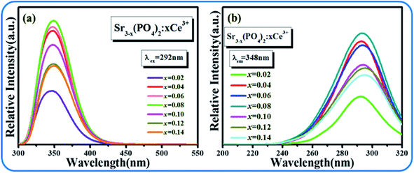 |
| | Fig. 3 Emission spectra and excitation spectra of SPO:xCe3+. | |
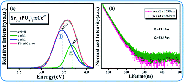 |
| | Fig. 4 (a) Gaussian fitting emission peaks of SPO:Ce3+; (b) SPO:Energy level diagram of Ce3+. | |
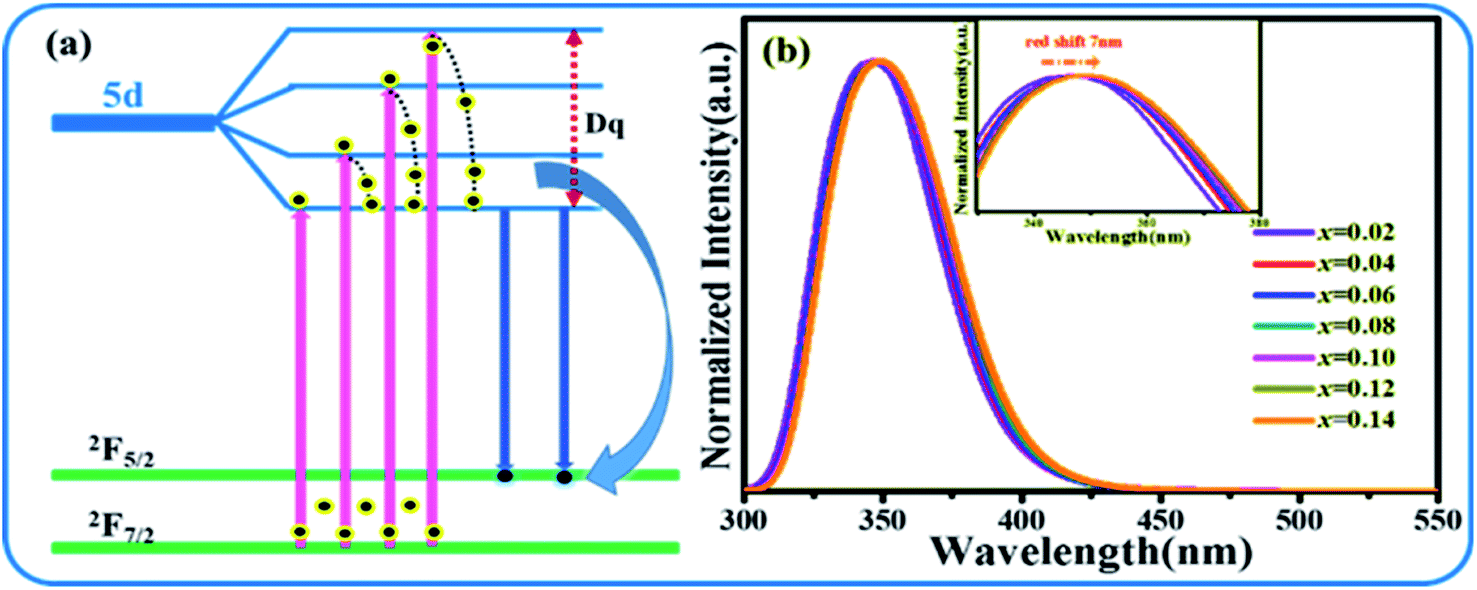
According to the above analysis, the transition process of Ce3+ is shown in Fig. 5(a). Fig. 5(b) presents the normalized emission spectra of SPO embedded with different concentration of Ce3+. With the gradual increment of Ce3+ into SPO, there is a red-shift of ∼7 nm for the emission band, which is likely to stem from the change of crystal field around Ce3+. As depicted in Fig. 5(a), the change of crystal field has effect on the 5d state of Ce3+, thus affecting the energy difference between the excited state and ground state. The larger the splitting of the 5d state, the closer the ground state and excited state. The cleavage of state is related to the charge of crystal field around central ion, and the cleavage becomes stronger when the charge of central ion is larger. In our work, with the increase of the doping concentration of Ce3+ ions, the distance of the luminescence center is shortened, and the non-radiative transition is enhanced. The loss of part of the energy leads to the shift of the spectrum to the long wave and the redshift of the spectrum.
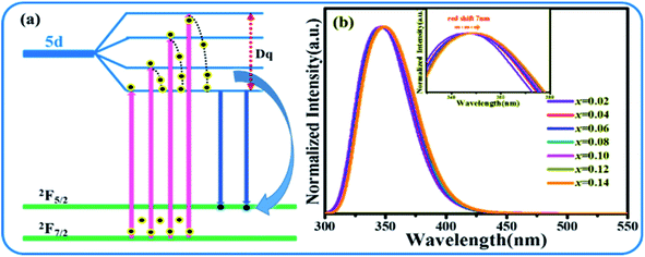 |
| | Fig. 5 (a) Energy diagram that shows the splitting condition of 5d state. (b) Emission spectra of SPO:xCe3+. | |
3.3 Luminescence characteristics of Sr3(PO4) 2:0.08Ce3+, zMn2+
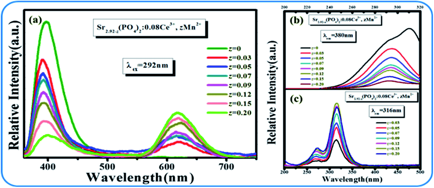
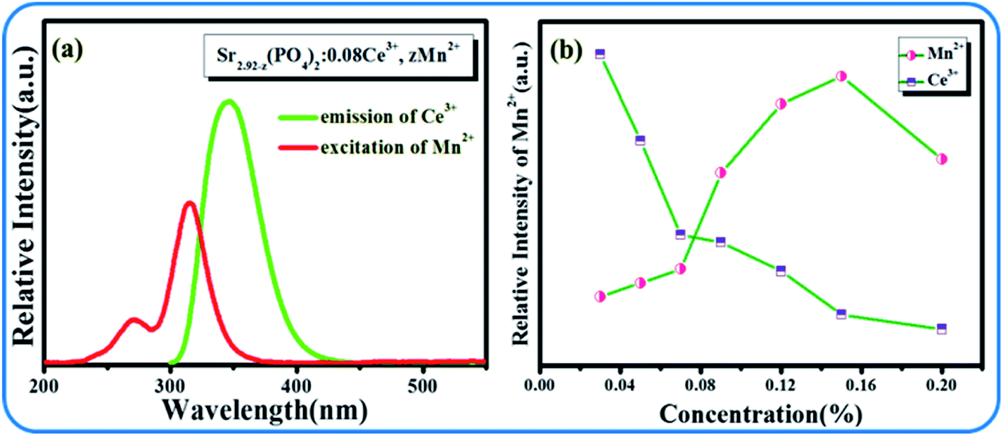
The emission spectra and excitation spectra of SPO:0.08Ce3+, zMn2+ are shown in Fig. 6. Upon the excitation at 292 nm, there are two main emission bands peaking at 380 and 616 nm that are ascribed to the emissions from Ce3+ and Mn2+. It can also be seen from the emission spectra that with the gradual increase of Ce3+, the emitting intensity of Mn2+ had been greatly improved. As clearly presented in Fig. 7(a), there is an overlap between the emission spectra of Ce3+ and the excitation spectra of Mn2+, suggesting a possible energy transfer from Ce3+ to Mn2+. With the gradual increase of Mn2+, the emission intensity of Ce3+ showed downtrend. These results indicate that the energy transfer from Ce3+ to Mn2+ exists in SPO.
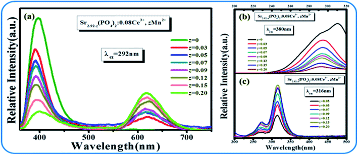 |
| | Fig. 6 (a) Emission spectra of SPO:0.08Ce3+, zMn2+. Excitation spectra SPO:0.08Ce3+, zMn2+ monitored at (b) 380 nm and at (c) 616 nm, respectively. | |
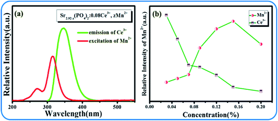 |
| | Fig. 7 (a) Excitation spectra of Mn2+ (red line) and emission spectra of Ce3+ (green line); (b) emission intensity of Mn2+ and Ce3+ with different Mn2+ concentrations. | |
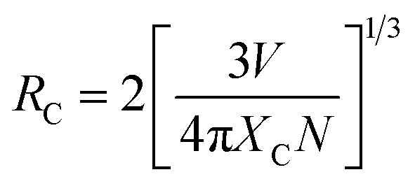
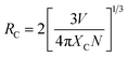
To further inspect this mechanism, we calculated the critical distance Rc between two types of ions according to the following formula20
| |
 | (1) |
where
N represents the number of cations in crystal lattice,
Xc is the concentration of doped ions, and
V represents the volume of crystal lattice. For SPO,
N and
V are 3 and 494.73 Å, respectively. The doping concentration of Mn
2+ was set to be the maximum doping concentration of
Xc = 0.20. The critical distance
Rc between Ce
3+ ions and Mn
2+ was calculated to be 11.64 Å. It is known that there are several kinds of mechanisms, including exchange interaction, multipolar interaction and radiation reabsorption. Only when the critical distance
Rc is less than 5 Å, the exchange interaction may occur. Moreover, the radiation reabsorption could also be excluded. Therefore, the energy transfer between Ce
3+ and Mn
2+ in SPO is the multipolar interaction.
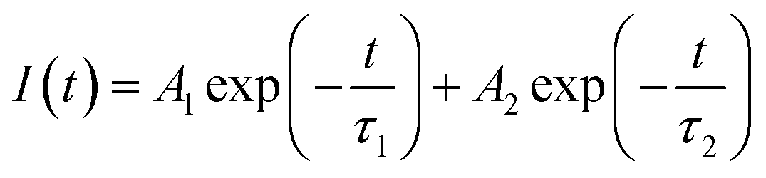
In order to more accurately determine the energy transfer between Ce3+ and Mn2+, the fluorescence decay curves of the 380 nm emission line were monitored, as shown in Fig. 8, and the calculated lifetimes were also listed in this figure. All the curves can be well fitted to a second-exponential function as follows21
| |
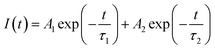 | (2) |
Where
I(
t) is the luminescence intensity,
A1 and
A2 are fitting consiants,
t is the time, and
τ1 and
τ2 are the lifetimes of the exponential component. It can be seen from
Fig. 8 that the lifetime of Ce
3+ decreased gradually with the gradual increase of doping concentration of Mn
2+. It confirms the presence of energy transfer from Ce
3+ to Mn
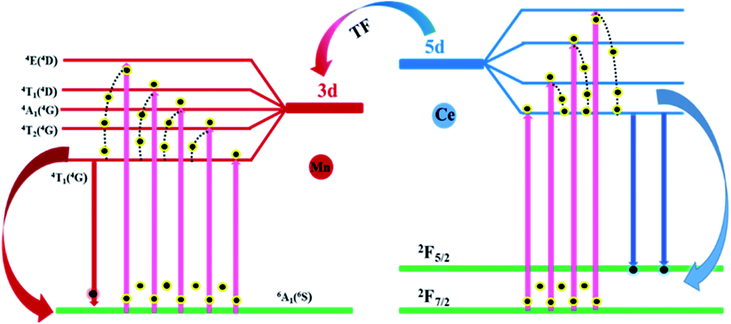
2+, and the specific processes are shown in
Fig. 9. Upon excitation at 292 nm, the Ce
3+ ions jump from 4f to 5d state and then to the final emitting state, followed by the generation of emission. Meanwhile, because the energy level of Mn
2+ is lower than that of Ce
3+, some Ce
3+ ions will transition from 5d state to the 3d state of Mn
2+, leading to the luminescence of Mn
2+.
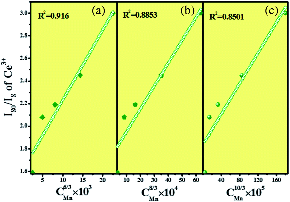
Fig. 10 shows the relationship between
Is0/
Is and
cα/3, and
α was fitted to be 6. It indicates that the energy transfer between Ce
3+ and Mn
2+ in SPO belongs to the dipole–dipole interaction.
 |
| | Fig. 8 Decay curves of SPO:0.08Ce3+, zMn2+. | |
 |
| | Fig. 9 Energy transfer mechanism diagram of SPO:0.08Ce3+, zMn2+. | |
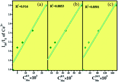 |
| | Fig. 10 Dependence of Is0/Is on (a) C6/3, (b) C8/3, (c) C10/3. | |
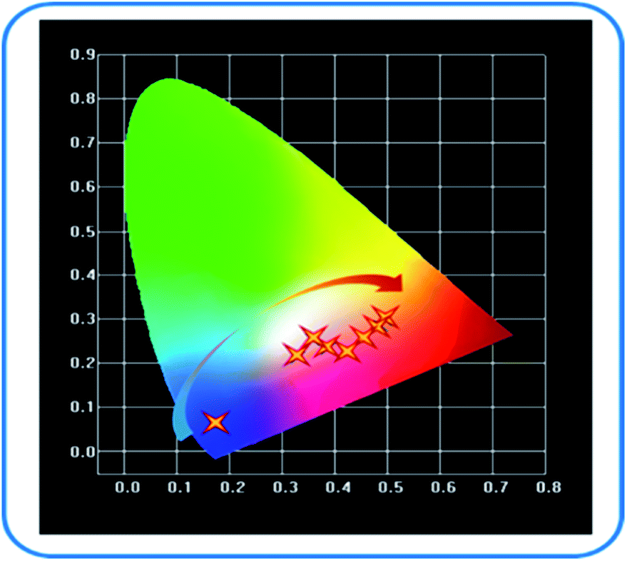
According to the emission spectra of samples, the color coordinate diagram of SPO:0.08Ce3+, zMn2+ was obtained, as shown in Fig. 11. It can be seen from this CIE diagram that with the rise of doping concentration of Mn2+, the emission color of SPO:0.08Ce3+, zMn2+ moves from blue to orange-red. It reveals that Ce3+ has a significant effect on the luminescence of Mn2+. Therefore, a series of phosphors with variable colors can be obtained.
 |
| | Fig. 11 SPO:0.08Ce3+, zMn2+ color coordinate changes. | |
3.4 Analysis of luminescence characteristics of Sr3(PO4)2:0.08Ce3+, yTb3+ and 0.05Mn2+
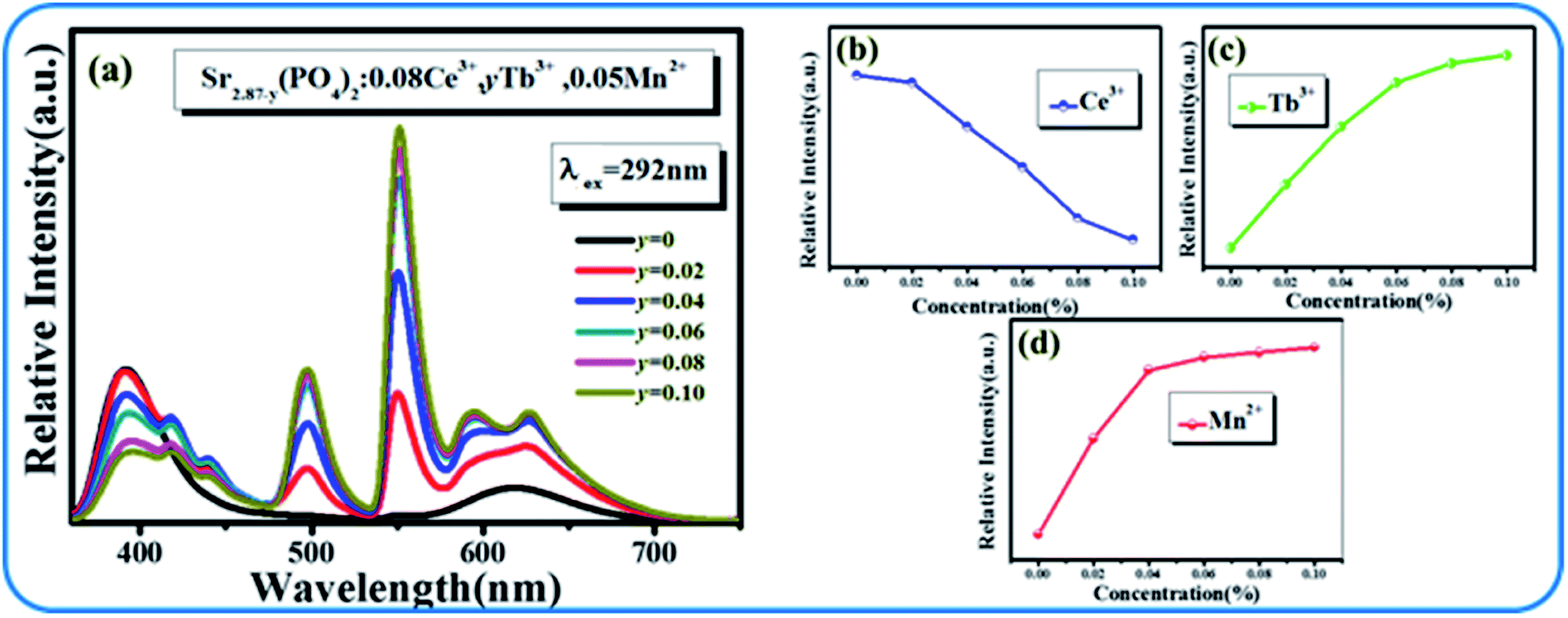
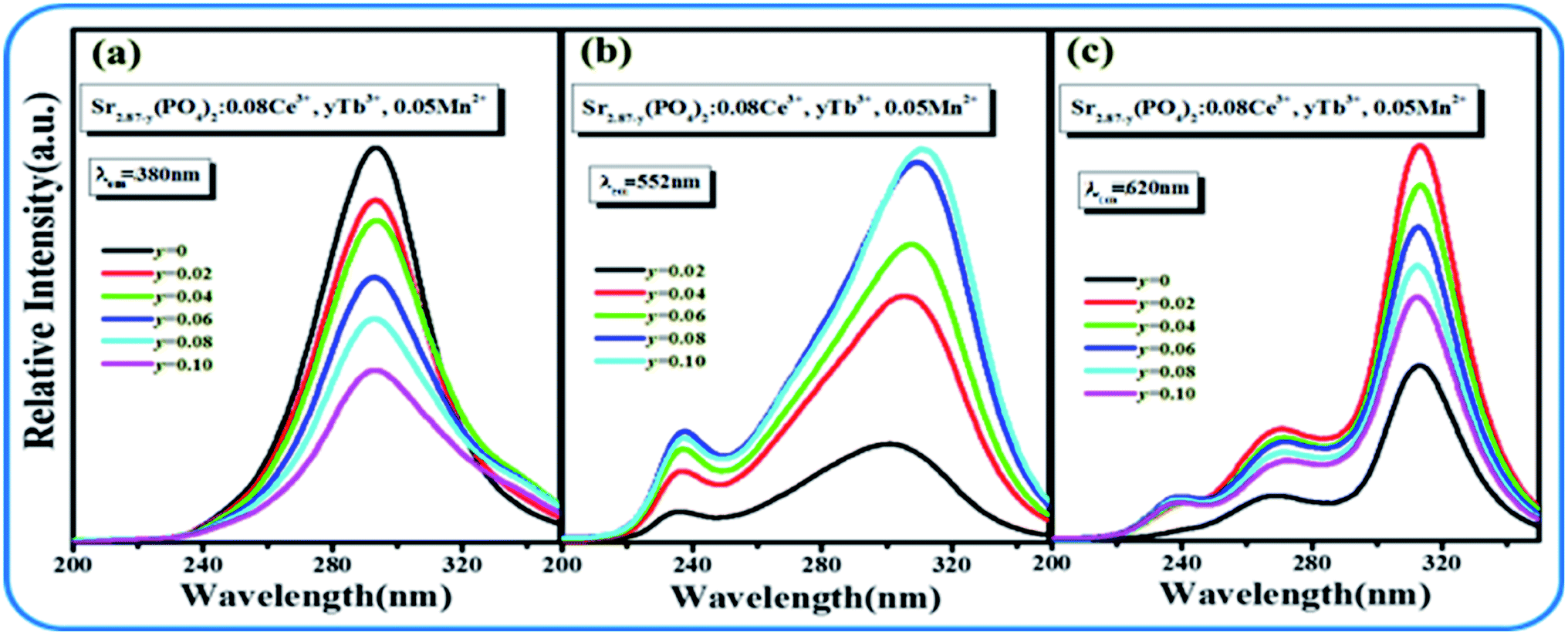
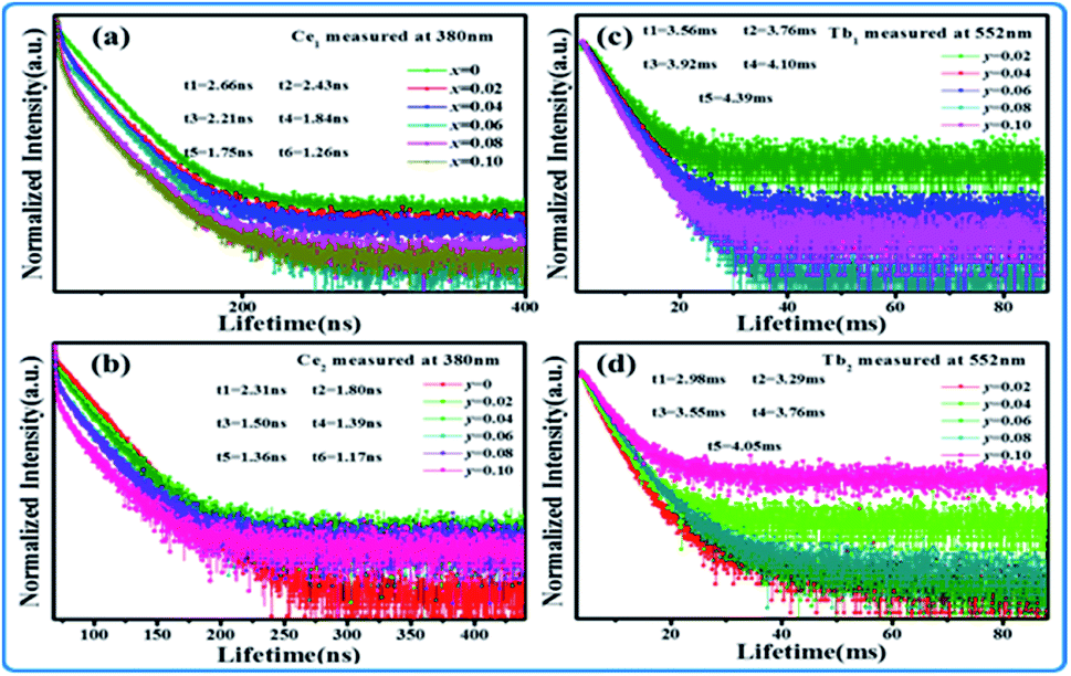
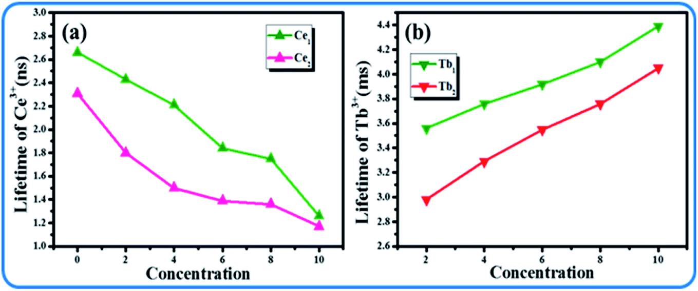
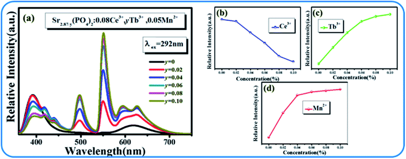
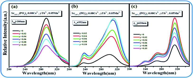
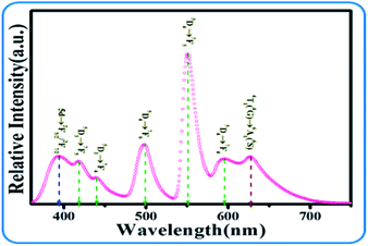
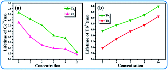
Although the emission color of SPO:0.08Ce3+, zMn2+ can be tuned from blue to orange-red, this phosphor lacks green light, which hinders the production of white emission. To solve this problem, Tb3+ ion, which is known to be a typical luminescent center for green light, is introduced into the phosphor of SPO:Ce3+, Mn2+, of which the emission spectra are presented in Fig. 12(a). Fig. 12(b–d) shows the emission intensity of Ce3+, Tb3+ and Mn2+ as a function of doping concentration. With the increase of Tb3+, the emission intensity of Ce3+ decreased, while that of Tb3+ and Mn2+ gradually increased. Fig. 13(a–c) represent the excitation spectra of Ce3+, Tb3+, and Mn2+, and Fig. 14 presents the affiliations corresponding to the emission peak of SPO:0.08Ce3+, yTb3+, 0.05Mn2+. The 380 nm emission line corresponds to the 5d → 2F5/2/2F7/2 transition of Ce3+. The emission bands at 420, 440, 500, 550 and 598 nm are ascribed to the 5D3 → 7F5, 5D3 → 7F4, 5D4 → 7F6, 5D4 → 7F5 and 5D4 → 7F4 transitions of Tb3+, respectively. The 625 nm emission line comes from the 4T1(4G)–6A1(6S) transition. From the emission spectra, it can be seen that the Ce3+ emission decreased while the emission intensity of Tb3+ and Mn2+ increased, which is likely attributed to the energy transfer from Ce3+ to Tb3+ and Mn2+. The fluorescence decay curves of Ce3+ and Tb3+ ions in SPO:0.08Ce3+, yTb3+ and SPO:0.08Ce3+, yTb3+, 0.05Mn2+ were measured, as shown in Fig. 15(a–d). And the calculated lifetimes are depicted in Fig. 16(a and b). From the emission spectra, it can be seen that the decrease rate of Ce2 is higher than that of Ce1, while the change rate of the lifetime of Tb3+ is almost a constant, confirming that the increase of Mn2+ emission is due to the energy transfer from Ce3+.
 |
| | Fig. 12 (a) Emission spectra of SPO:0.08Ce3+, yTb3+ and 0.05Mn2+; Emission intensities of Ce3+ (b), Tb3+ (c) and Mn2+, respectively (d). | |
 |
| | Fig. 13 Excitation spectra of Ce3+ (a), Tb3+ (b) and Mn2+ (c), respectively. | |
 |
| | Fig. 14 Energy level transition diagram of SPO:0.08Ce3+ and yTb3+, 0.05Mn2+. | |
 |
| | Fig. 15 Decay curve of (a) Ce1, (b) Ce2, (c) Tb1 and (d) Tb2. | |
 |
| | Fig. 16 Lifetime of (a) Ce3+ and (b) Tb3+ as a function of doping concentration. | |
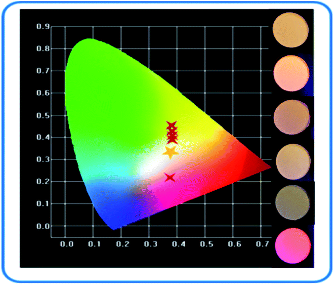
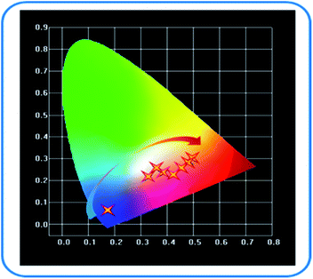
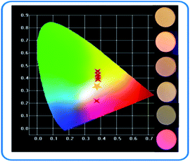
It can be seen that the main emission peak of SPO:0.08Ce3+, yTb3+, 0.05Mn2+ is located at about 550 nm, which perfectly complements the missing green light of the emission spectrum of SPO:0.08Ce3+, zMn2+. The color rendering index, color coordinates and dependence on temperature of SPO:0.08Ce3+, yTb3+, 0.05Mn2+ are given in Table 3. According to this table, the color coordinate of SPO:0.08Ce3+, yTb3+, 0.05Mn2+ is depicted in Fig. 17. Obviously, the chromaticity coordinate could locate in the white light range via a careful adjustment of the doping concentration of Tb3+.
Table 3 Color rendering index, color coordinates and color temperature of SPO:0.08Ce3+, yTb3+, 0.05Mn2+
| SPO:0.08Ce3+, yTb3+, 0.05Mn2+ |
CRI |
(X, Y) |
CCT (K) |
| y = 0 |
6.3 |
(0.373, 0.217) |
3743 |
| y = 0.02 |
45.5 |
(0.376, 0.337) |
3777 |
| y = 0.04 |
59.3 |
(0.380, 0.391) |
4115 |
| y = 0.06 |
62.6 |
(0.376, 0.426) |
4394 |
| y = 0.08 |
59.4 |
(0.382, 0.446) |
4367 |
| y = 0.10 |
57.8 |
(0.383, 0.455) |
4373 |
 |
| | Fig. 17 Color coordinates of SPO:0.08Ce3+, yTb3+, 0.05Mn2+. | |
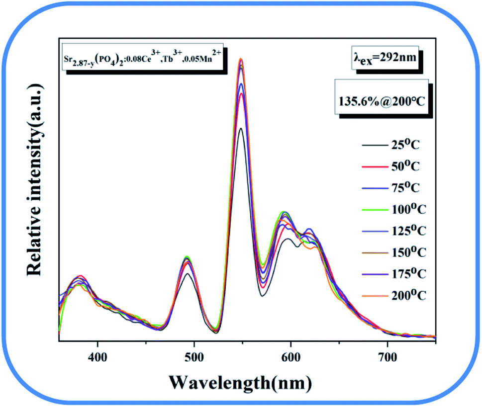
The temperature spectrum of the sample is shown in Fig. 18. The picture shows that the luminous intensity can still maintain 135.6% of that at room temperature at 200 degrees, showing the good temperature stability of the material.
 |
| | Fig. 18 Temperature spectrum of Sr2.87−y(PO4)2:0.08Ce3+, Tb3+, 0.05Mn2+. | |
4 Conclusions
In summary, a series of SPO:xCe3+, SPO:xCe3+, zMn2+ and SPO:0.08Ce3+, yTb3+, 0.05Mn2+ phosphors were synthesized. For Sr3(PO4)2:Ce3+, Mn2+, the efficient energy transfer from Ce3+ to Mn2+ was observed and analyzed in detail, and the tunable emission color of Sr3(PO4)2:Ce3+–Mn2+ was realized by the energy transfer. In addition, Tb3+ ion, which mainly emits green light, was further added into Sr3(PO4)2:Ce3+, Mn2+. Due to the addition of this green emission, the white emitting phosphors with good quality were obtained. At the same time, the energy transfer mechanisms among Ce3+, Tb3+ and Mn2+ ions were also analyzed in detail. The results show that Sr3(PO4)2:Ce3+, Mn2+, Tb3+ is a promising candidate for white LEDs.
Conflicts of interest
The authors declare no competing financial interest.
Acknowledgements
The work is supported by the National Natural Science Foundation of China (No. 51902080), the Natural Science Foundation of Hebei Province, China (No. E2019201223), the Personnel Training Project of Hebei Province, China (No. A201902005), and the Central Government to Guide Local Scientific and Technological Development (No. 206Z1102G, 216Z1101G).
References
- M. Shang, C. Li and J. Lin, How to produce white light in a single-phase host, Chem. Soc. Rev., 2014, 43(5), 1372–1386 RSC.
- S. Ye, F. Xiao and Y. X. Pan, et al., Phosphors in phosphor-converted white light-emitting diodes: Recent advances in materials, techniques and properties, Mater. Sci. Eng., R, 2010, 71(1), 1–34 CrossRef.
- C. C. Lin and R. S. Liu, Advances in phosphors for light-emitting diodes, J. Phys. Chem. Lett., 2011, 2(11), 1268–1277 CrossRef CAS PubMed.
- X. Li, P. Li and Z. Wang, et al., Color-tunable luminescence properties of Bi3+ in Ca5(BO3)3F via changing site occupation and energy transfer, Chem. Mater., 2017, 29(20), 8792–8803 CrossRef CAS.
- M. Chen, Z. Xia and M. S. Molokeev, et al., Tuning of photoluminescence and local structures of substituted cations in Sr2Ca(PO4)2-(1–x)Ca10Li(PO4)7:Eu2+ phosphors, Chem. Mater., 2017, 29(3), 1430–1438 CrossRef CAS.
- J. Huo, L. Wei and B. Shao, et al., Color tunable emission via efficient Ce3+→Tb3+ energy transfer pair in MgYSi2O5N oxynitride phosphor for near-UV-pumped white LEDs, Dyes Pigm., 2017, 139, 174–179 CrossRef CAS.
- D. Yun, L. Liangbo and L. Min, et al., Efficient manganese luminescence induced by Ce3+-Mn2+ energy transfer in rare earth fluoride and phosphate nanocrystals, Nanoscale Res. Lett., 2011, 6(1), 119 CrossRef PubMed.
- Y. Jia, L. Wei and N. Guo, et al., Realization of color hue tuning via efficient Tb3+–Mn2+ energy transfer in Sr3Tb(PO4)3: Mn2+, a potential near-UV excited phosphor for white LEDs, Phys. Chem. Chem. Phys., 2013, 15(16), 6057 RSC.
- C. H. Huang, T. M. Chen and W. R. Liu, et al., A Single-Phased Emission-Tunable Phosphor Ca9Y(PO4)7: Eu2+,Mn2+ with Efficient Energy Transfer for White-Light-Emitting Diodes, ACS Appl. Mater. Interfaces, 2010, 2(1), 259–264 CrossRef CAS.
- P. Chen, New phenomenon, mechanism and application of rare earth ion fluorescence. Zhejiang University, 2016. in Chinese Search PubMed.
- Y. C. Jia, Y. J. Huang and Y. H. Zheng, et al., Color point tuning of Y3Al5O12:Ce3+ phosphor via Mn2+-Si4+ incorporation for white light generation, J. Mater. Chem., 2012, 22(30), 15146–15152 RSC.
- L. Ye, X. Peng and S. Zhang, et al., Photoluminescence properties of Ca-doped BaMgAl10O17:Eu2+,Mn2+ blue phosphor using BaF2 and CaF2 as co-flux, J. Rare Earths, 2014, 32(12), 1109–1113 CrossRef CAS.
- N. Guo, H. You and Y. Song, et al., White-light emission from a single-emitting-component Ca9Gd(PO4)7:Eu2+,Mn2+ phosphor with tunable luminescent properties for near-UV light-emitting diodes, J. Mater. Chem., 2010, 20(41), 9061–9070 RSC.
- Y. Dongyan, W. Xingya, Y. Gongqin and C. Jieliang, Research Progress of Rare Earth Doped Phosphate Phosphors, Mater. Rev., 2020, 34, 41–47 Search PubMed.
- Z. Fangyi, C. Hao, S. Zhen and L. Quanlin, Structural Confinement for Cr3+ Activators toward Efficient Nearinfrared Phosphors with Suppressed Concentration Quenching, Chem. Mater., 2021, 33(10), 3621–3630 CrossRef.
- Y. Wang, J. Ding and Y. Wang, Preparation and photoluminescence properties with the site-selected excitations of Bi3+-activated Ba3Sc4O9 phosphors, J. Am. Ceram. Soc., 2017, 100(6), 2612–2620 CrossRef CAS.
- R. Cui, X. Guo and X. Gong, et al., Enhancing red emission of CaBi2Ta2O9: Eu3+ phosphor by La3+ co-doping, J. Mater. Sci.: Mater. Electron., 2016, 27(9), 9656–9660 CrossRef CAS.
- P. Dorenbos, 5d -level energies of Ce3+, and the crystalline environment.I.Fluoridecompounds, Phys. Rev. B: Condens. Matter Mater. Phys., 2000, 62(23), 15640–15649 CrossRef CAS.
- Y. Q. Li, N. Hirosaki and R. J. Xie, et al., ChemInform Abstract: Yellow-Organe-Emitting CaAlSiN3:Ce3+ Phosphor: Structure, Photoluminescence, and Application in White LEDs, ChemInform, 2008, 20(21), 6704–6714 CAS.
- G. Blasse, J. Solid State Chem., 1986, 62, 207–211 CrossRef CAS.
- Z. Ming, J. Zhao, H. C. Swart and Z. Xia, J. Rare Earths, 2020, 38, 506 CrossRef CAS.
|
| This journal is © The Royal Society of Chemistry 2022 |
Click here to see how this site uses Cookies. View our privacy policy here. 
 Open Access Article
 This Open Access Article is licensed under a Creative Commons Attribution-Non Commercial 3.0 Unported Licence
 *a,
Hao Suoa,
Dawei Wangb,
Jinxin Zhaob and
Panlai Li
*a,
Hao Suoa,
Dawei Wangb,
Jinxin Zhaob and
Panlai Li