
 Open Access Article
 This Open Access Article is licensed under a Creative Commons Attribution-Non Commercial 3.0 Unported Licence
Au nanoparticle-decorated TiO2 hollow fibers with enhanced visible-light photocatalytic activity toward dye degradation†
Gasidit Panomsuwan *a,
Sittan Wongcharoena,
Chayanapat Chokradcharoenb,
Mongkol Tipplookc,
Oratai Jongprateepa and
Nagahiro Saitob
*a,
Sittan Wongcharoena,
Chayanapat Chokradcharoenb,
Mongkol Tipplookc,
Oratai Jongprateepa and
Nagahiro Saitob
aDepartment of Materials Engineering, Faculty of Engineering, Kasetsart University, Bangkok 10900, Thailand. E-mail: gasidit.p@ku.ac.th
bDepartment of Chemicals System Engineering, Graduate School of Engineering, Nagoya University, Nagoya 464-86-3, Japan
cResearch Initiative for Supra-Materials, Shinshu University, Nagano 380-8553, Japan
First published on 20th December 2021
Abstract
TiO2 hollow fibers (THF) were prepared by a template method using kapok as a biotemplate and subsequently decorated by plasmonic Au nanoparticles using a solution plasma process. The THF exhibited an anatase phase and a hollow structure with a mesoporous wall. Au nanoparticles with a diameter of about 5–10 nm were uniformly distributed on the THF surface. Au nanoparticles-decorated TiO2 hollow fibers (Au/THF) have enhanced photocatalytic activity toward methylene blue degradation under visible light-emitting diode (Vis-LED) as compared to pristine THF and P25. This could be attributed to combined effects including effective light-harvesting by a hollow structure, large surface area due to a mesoporous wall of THF, and visible-light absorption and efficient charge separation induced by Au nanoparticles. The Au/THF also showed good recyclability and separation ability.
Introduction
Titanium dioxide (TiO2) is the most promising photocatalyst material for environmental remediation applications especially in the degradation of several problematic pollutants in wastewater (i.e., dyes,1 phenol,2 pesticides,3 and petrochemical hydrocarbons4). It has efficient photocatalytic activity, low cost, high photochemical stability, and nontoxicity.5 However, pristine TiO2 can absorb only the ultra-violet (UV) region, which is a small fraction of solar light (<5%) due to its relatively wide band gap (typically ∼3.2 eV for anatase and ∼3.0 eV for rutile).6,7 This is a major barrier for TiO2 that limits its practical and broader applications in the visible-light region (approximately 45% of solar light).To realize the visible-light photocatalytic activity, the band gap of TiO2 can be tuned to be narrower by appropriately doping with metal cations (e.g., Cu,8 Ni,9 W,10 etc.) or non-metal anions (e.g., B,11 N,12 S,13 etc.) and introducing oxygen vacancy defects into the TiO2 lattice.14,15 The dopants and vacancy defects could create localized energy states below the conduction band (CB) or above the valence band (VB), thus leading to a narrow band gap and visible-light absorption.8–15 In addition, surface decoration of TiO2 with Au nanoparticles (AuNPs) is an effective strategy to attain visible-light photocatalytic activity because the AuNPs can absorb the visible light via the surface plasmon resonance (SPR) effect.16,17 Upon visible-light irradiation, the photogenerated electrons from AuNPs are injected into the CB of TiO2 leaving behind holes in the AuNPs. These electrons and holes can further catalyze the redox reactions, thus leading to the formation of hydroxyl radicals (˙OH). The ˙OH is highly reactive to oxidize and degrade most organic pollutants into benign products.
Over the past years, numerous endeavors have studied and focused on AuNPs decorated with various nanoscale TiO2 forms with tailored phases and morphologies (i.e., nanoflower,18 nanotube,19 nanocup,20 etc.). However, aggregation formation during the photocatalytic reaction and poor separation ability of nanoscale TiO2 from treated wastewater for reuse are major constraints that hinder their practical applications.6,7 Although these problems can be untangled by using microscale TiO2, its photocatalytic activity is still less than nanoscale TiO2. Therefore, the development of a micro-nano TiO2 hierarchical structure decorated with AuNPs has emerged as a promising approach to meet the requirements of practical photocatalysts including visible-light response, low aggregation, and good separation ability.
Here, we report a micro-nano hierarchical TiO2 structure, which is a hollow microfiber with a mesoporous wall. This unique structure could enhance the photocatalytic activity of TiO2 via multilight scattering within a hollow cavity and high surface area promoted by the mesoporous wall.21–23 The TiO2 hollow fibers (THF) have been successfully prepared via several synthetic routes such as templating,23–26 spinning–sintering,27 electrospinning methods.22,28 A template method using natural fibers as a biotemplate was selected in this work due to its simplicity and cost effectiveness for the preparation of THF.24–26 For surface decoration, AuNPs were synthesized by the solution plasma process (SPP) through the sputtering of Au electrodes. In comparison with conventional chemical reduction, SPP offers several advantages for the synthesis of AuNPs, including simplicity, purity, no use of reducing agents, and short-time synthesis without further purification.29–31 The morphology, crystalline structure, surface area, as well as optical and chemical properties of Au/THF were investigated and compared with pristine THF and commercial P25. The visible-light photocatalytic activity was also examined by measuring the degradation of methylene blue (MB) dye under visible-light-emitting diode (Vis-LED) irradiation.
Experiment
Materials and chemicals
Kapok fibers were obtained from kapok trees (Ceiba pentandra) in Chiang Rai Province, Thailand. Titanium butoxide (TiC16H36O4, purity, >99.5%) was purchased from Tokyo Chemical Industry Co., Ltd. Methylene blue (C16H18ClN3S) and adipic acid (C6H10O4, purity 99%) were purchased from Sigma Aldrich. Ethanol (C2H5OH, 99.9% purity), acetone (C3H6O, 99.5% purity), sodium sulfate (Na2SO4, 99.0% purity) were purchased from RCI LabScan Ltd. Aeroxide® TiO2 P25 was supplied by Nippon Aerosil Co., Ltd. Fluorine-doped tin oxide (FTO) coated on glass substrate (TEC15, 15 Ω sq−1) was purchased from Greatcell Solar Materials Pty Ltd. Au wire (1 mm in diameter, 99.95% purity) was purchased from Nilaco Corp. Ultrapure water (18.2 MΩ cm at 25 °C) was obtained from a Millipore Direct-Q® 5 UV water purification system. All chemicals were of analytical grade and used as received without further purification.Synthesis of TiO2 hollow fibers (THF) by template method
3 mL of titanium butoxide was slowly dropped into 150 mL of ethanol and then stirred for 1 h at room temperature. The 1 g of dried and loose kapok fibers was impregnated in the mixture for 3 h and then dried naturally in air at room temperature for 18 h. The Ti precursor was adsorbed on the surface of the kapok fibers. The calcination process was performed at 450 °C for 1 h in a muffle furnace (Linn High Term GmbH) under air atmosphere with a heating rate of 5 °C min−1 and cooled naturally to room temperature. During calcination, the kapok fiber templates were removed due to thermal decomposition at 450 °C as confirmed by thermogravimetric analysis (TGA) (Fig. S1†). At the same time, a crystalline TiO2 phase with a hollow structure was formed.Preparation of AuNPs decorated TiO2 hollow fibers (Au/THF) by solution plasma process
A pair of Au wires covered with an insulating ceramic tube was set at a gap distance of 0.5 mm at the center of a glass beaker. Next, 0.02 M adipic acid (80 mL) with dispersion of THF (0.1 g) was poured into the beaker and stirred at 400 rpm constantly for 10 min. A bipolar-pulse voltage was supplied to the Au electrode pair by connecting to an MPS-06K06C bipolar pulse generator (Kurita Seisakusho Co., Ltd.). The frequency and pulse duration were fixed at 15 kHz and 2 μs, respectively. The discharge time was 4 min. The schematic diagram of SPP system is depicted in Fig. S2.† The AuNPs were produced through sputtering from the Au electrode surface once the plasma emerged. The AuNPs diffused out from the plasma zone to the liquid phase and then deposited on the THF surface, thus resulting in the formation of Au/THF. After SPP, the Au/THF was separated from the solution by centrifugation at 12![[thin space (1/6-em)]](https://www.rsc.org/images/entities/char_2009.gif) 000 rpm for 10 min and washed three times by ultrapure water. The resulting samples were then air-dried at 60 °C overnight. The THF and Au/THF were fluffy with white and pink color, respectively (Fig. S3†). The overall synthesis process of Au/THF is schematically illustrated in Fig. 1.
000 rpm for 10 min and washed three times by ultrapure water. The resulting samples were then air-dried at 60 °C overnight. The THF and Au/THF were fluffy with white and pink color, respectively (Fig. S3†). The overall synthesis process of Au/THF is schematically illustrated in Fig. 1.
 | ||
| Fig. 1 Schematic diagram depicting the overall synthesis of Au/THF by template method and SPP. | ||
Characterizations
The physical and chemical properties of THF and Au/THF were investigated systematically. The morphology was observed with a JSM-7600F JEOL field-emission scanning electron microscope at an acceleration voltage of 1 kV. The quantity and dispersion of Au nanoparticles on THF were evaluated on an AZtecOne energy dispersive spectroscopy system from Oxford Instruments equipped with a Hitachi SU3500 SEM scanning electron microscope at an acceleration voltage of 15 kV. The size of AuNPs and microstructure were investigated with a JEM-3100F JEOL transmission electron microscope at an acceleration voltage of 300 kV. Diffuse reflectance spectroscopy (DRS) was examined on an Agilent Technologies Cary 5000 UV-vis-NIR spectrophotometer equipped with an integrating sphere. Pure barium sulfate powder (BaSO4) was used as a standard for background measurements. The reflectance spectra were converted to the equivalent absorption coefficient by the Kubelka–Munk (K–M) function. N2 adsorption–desorption isotherms were performed on a Micromeritics 3Flex surface characterization analyzer at liquid nitrogen temperature (−196 °C). The relative pressure (P/P0) was varied from 0.01 to 0.99. Prior to the measurement, the samples were degassed at 150 °C for 6 h under vacuum using a Micromeritics Smart VacPrep system to ensure a dry and clean surface. The phase structure was identified using a Rigaku Ultima IV diffractometer with monochromatic Cu Kα radiation (λ = 0.15406 nm) operating at 40 kV and 40 mA. Fourier-transform infrared spectroscopy (FTIR) spectra were collected using a Bruker Alpha-E spectrometer in the transmission mode within wavenumber of 500–4000 cm−1. The samples were mixed with potassium bromide (KBr) and then pressed into the pellet for the measurement. The chemical bonding states were investigated on a Kratos Axis Ultra DLD X-ray photoelectron spectrometer equipped with monochromatic Al Kα as an X-ray source at the anode voltage of 15 kV. The binding energy (BE) was calibrated using the C 1s peak (284.5 eV).Photocurrent and electrochemical impedance spectroscopy measurements
The photocurrent and electrochemical impedance spectroscopy (EIS) of THF, Au/THF, and P25 were performed on a PalmSens 4 potentiostat with a standard three-electrode system. The working electrode was prepared as follows. The FTO-coated glass substrates were cut and subsequently cleaned with acetone and ethanol for 15 min each, followed by air-drying under ambient conditions. The sample powder (5 mg) was ultrasonicated in 1 mL of ethanol to obtain a homogeneous suspension. The suspension was spread onto FTO glass with a working area of 1 cm × 1 cm and then dried overnight under ambient condition. A copper wire was connected to the working electrode using silver paint and sealed with an insulating tape. The Ag/AgCl (in saturated KCl solution) and Pt coil were used as reference and counter electrodes, respectively. The working electrode was irradiated by Vis-LED lamp (50 W, Sylvania) in 0.5 M Na2SO4 aqueous solution. The photocurrent was measured at 0.6 V under Vis-LED irradiation with 50 s on/off time intervals. The EIS measurements were performed by applying AC potential of 5 mV at the frequency ranging from 100 mHz to 100 kHz under Vis-LED irradiation.Photocatalytic measurement
Photocatalytic activity of THF and Au/THF was evaluated by the degradation of methylene blue (MB) as a representative synthetic dye. The 10 ppm of MB solution (10 mg L−1, 2.70 × 10⁻⁵ M) was prepared and stirred in the absence of light (dark condition) for 24 h. 100 mg of photocatalyst was suspended in a glass beaker containing 100 mL of MB solution (dosage = 1 g L−1). The suspension was further stirred in the dark condition for 2 h to obtain the adsorption–desorption equilibrium. Next, a beaker containing a suspension was placed parallel to a Vis-LED lamp (10 cm away) in a black box with cooling fans to minimize the heat generated from the Vis-LED. A 1 mL of suspension was collected hourly and then centrifuged to separate the samples from the MB solution. The degradation of MB was evaluated via measurements of absorbance at 664 nm using a Hitachi U-2900 spectrophotometer with a rectangular 700 μL Micro Cuvette (Starna Scientific Ltd.). P25 was also tested as a benchmark using the same procedure for comparison.The recycling test was also investigated to evaluate reusability. After leaving the suspension for complete gravity sedimentation, the sample was collected and then washed with ultrapure water several times to remove residual MB molecules until the washed water was colorless. The cleaned sample was dried at 100 °C for 12 h prior to the photocatalytic recycling test for four cycles.
Results and discussion
Fig. 2a and b show SEM images of Au/THF. The Au/THF has a hollow structure with a diameter of 5–20 μm and length of 50–200 μm. The magnified view of the THF wall in the inset of Fig. 2b shows a uniform distribution of AuNPs (white dots) on the wall surface. Energy dispersive spectroscopy (EDS) mapping was also performed to confirm the distribution and estimate the amount of AuNPs over THF as shown in Fig. S4.† The signal of Au (red) was evenly detected on the entire THF region. The amount of Au was about 0.54 ± 0.05 at%. TEM images were further taken to investigate the microstructure of THF and AuNP as illustrated in Fig. 2c and d. The uniform dispersion of AuNPs (dark contrast) was observed on the Au/THF. The AuNPs had a round shape with a diameter of about 5–10 nm. A high-magnification TEM image (Fig. 2d) shows the clear lattice fringe for both THF and AuNPs regions. The electron diffraction in the inset of Fig. 2c demonstrates the clear ring pattern corresponding to both TiO2 and Au lattices. These results indicate that both THF and AuNPs had good crystallinity. X-ray diffraction (XRD) analysis (Fig. S5†) verified that THF possessed a single anatase phase without other crystalline phases. However, the diffraction peaks of the Au phase were not observed due to the low amount of AuNPs below the detection limit. This result agrees with several prior works.32–36 | ||
| Fig. 2 (a and b) SEM images and (c and d) TEM images of Au/THF. The electron diffraction pattern is shown in the inset of (c). | ||
The surface area and porosity of THF and Au/THF were evaluated using the N2 adsorption–desorption isotherms (Fig. 3a). According to the International Union of Pure Applied Chemistry (IUPAC), the isotherms of both THF and Au/THF corresponded to a type IV with H4 pore characteristics referring to a mesoporous structure with a narrow slit-pore shape.37 The specific surface area of Au/THF calculated using the Brunauer–Emmett–Teller (BET) method was 62.1 m2 g−1, which is greater than that of THF (32.6 m2 g−1). The pore-size distributions determined by the Barrett–Joyner–Halenda (BJH) method of THF and Au/THF are shown in Fig. 3b. The average pore size was estimated to be 4.2 and 6.2 nm for THF and Au/THF, respectively. The larger specific surface area of Au/THF over THF was attributable to the following reasons: (i) the creation of a mesoporous wall and a more accessible surface caused by plasma treatment in acid solution, and (ii) the development of rougher wall surface induced by the surface decoration of AuNPs. A large surface area and mesoporosity of photocatalysts can enhance the light-harvesting efficiency to promote photocatalytic activity.38,39
 | ||
| Fig. 3 (a) N2 adsorption–desorption isotherm and (b) BJH pore-size distribution of THF and Au/THF. (c) Absorption spectra and (d) PL spectra of THF, Au/THF, and P25. | ||
Diffuse reflectance spectra (DRS) of THF, Au/THF, and P25 are presented in Fig. 3c. The THF showed a sharp absorption edge at approximately 400 nm, which was close to that of P25. The Au/THF had a similar absorption edge but possessed a broad absorption covering the wavelength from 400 to 800 nm. The broad peak centered at about 540 nm was seen via the SPR effect of AuNPs. The absorption spectrum of colloidal AuNPs synthesized using similar conditions with the absence of THF was also recorded and is shown in Fig. S6.† The results had a pronounced absorption peak of SPR at 513 nm, which corresponded to a particle size of about 5 nm according to Mie theory.40 This calculated size of AuNPs agreed well with TEM. However, the SPR peak gradually shifted to a longer wavelength and also suppressed to a broad feature when AuNPs were deposited on the THF support. The shift of SPR peak of Au/THF was attributed to the photoinduced charge separation at the interface between AuNPs and THF. Similar findings were previously reported in several works on Au/TiO2.41–43
The band gap of THF, Au/THF, and P25 estimated from the Tauc plot (Fig. S7†) were 3.11, 3.05, and 3.11 eV, respectively. A slight downward shift in band gap of Au/THF was due to the creation of metal–semiconductor Schottky junction at the interface between AuNPs and THF.17,44 Photoluminescence (PL) spectra of THF, Au/THF, and P25 were also recorded at an excitation wavelength of 420 nm to confirm the electron–hole recombination effect. Fig. 3d shows that the PL intensity at about 453 nm was: P25 > THF > Au/THF. A remarkable decrease in the PL intensity of Au/THF indicates a low recombination rate of photogenerated electrons and holes under visible-light irradiation as compared to THF and P25.
XPS measurements were further performed to examine the chemical bonding state of THF and Au/THF. The XPS survey spectra in Fig. 4a demonstrates that both THF and Au/THF are comprised of Ti 2p, O 1s, and Au 4f peaks. The XPS Ti 2p spectrum of THF showed the doublet peaks of Ti 2p3/2 and Ti 2p1/2 located at 459.4 eV and 465.2 eV, respectively, which are the characteristic binding energies of Ti4+ in anatase TiO2 (Fig. 4b).44–48 For Au/THF, the Ti 2p doublet peaks gradually shifted about 0.2 eV to a higher binding energy, thus indicating the electron transfer between AuNPs and THF supports.36,44,45,49 A slight shift in binding energy was also observed for the XPS O 1s spectrum of Au/THF (Fig. 4c). The XPS O 1s spectra of THF and Au/THF were deconvoluted into two peaks. The main peak at low binding energy (530.6–530.7 eV) refers to lattice oxygen in TiO2 structure (OL), while the shoulder peak at high binding energy (532.3–532.4 eV) is associated with the adsorbed oxygen and OH groups (OC).44–46 The OC/OL ratio of Au/THF was higher than THF, thus indicating higher oxygen species on the Au/THF surface. These results are consistent with FTIR results, which showed higher absorbance of OH band for Au/THF as compared to THF (Fig. S8†). The presence of more OH groups on Au/THF was reasonable due to the effect of acid and plasma treatments during synthesis. The generation of highly oxidative species from plasma could result in the surface functionalization on Au/THF. Fig. 4d shows that the XPS Au 4f had doublet peaks at 87.8 and 84.5 eV corresponding to the zero-valence state (Au0) of Au 4f7/2 (87.8 eV) and Au 4f5/2 (84.1 eV), which are consistent with the values reported in literature.36,44,50 This result again confirmed the presence of AuNPs on the THF in accordance with the discussion above.
 | ||
| Fig. 4 XPS measurements of THF and Au/THF: (a) XPS survey spectra. High-resolution XPS spectra of (b) Ti 2p, (c) O 1s, and (d) Au 4f. | ||
The photocurrent density versus time was measured to evaluate the photoresponse of all samples. The transient photocurrent response of THF, Au/THF, and P25 were measured for several on–off cycles of Vis-LED irradiation (Fig. 5a). A rise and fall of the photocurrent to the switching on and off of the Vis-LED was clearly observed for all samples. The photocurrent density was found in the following order: Au/THF > THF > P25. The highest photocurrent density of Au/THF indicates its strong visible-light response with more effective charge separation. EIS analysis was also performed to examine the charge transfer resistance. Fig. 5b shows the EIS Nyquist plot of THF, Au/THF, and P25 electrodes upon the Vis-LED irradiation. The Au/THF had the smallest arc radius as compared to THF and P25, suggesting the low charge transfer resistance and low recombination rate of Au/THF.51 This result is in line with its highest photocurrent transient response and the lowest PL intensity, which confirms the visible-light response of Au/THF.
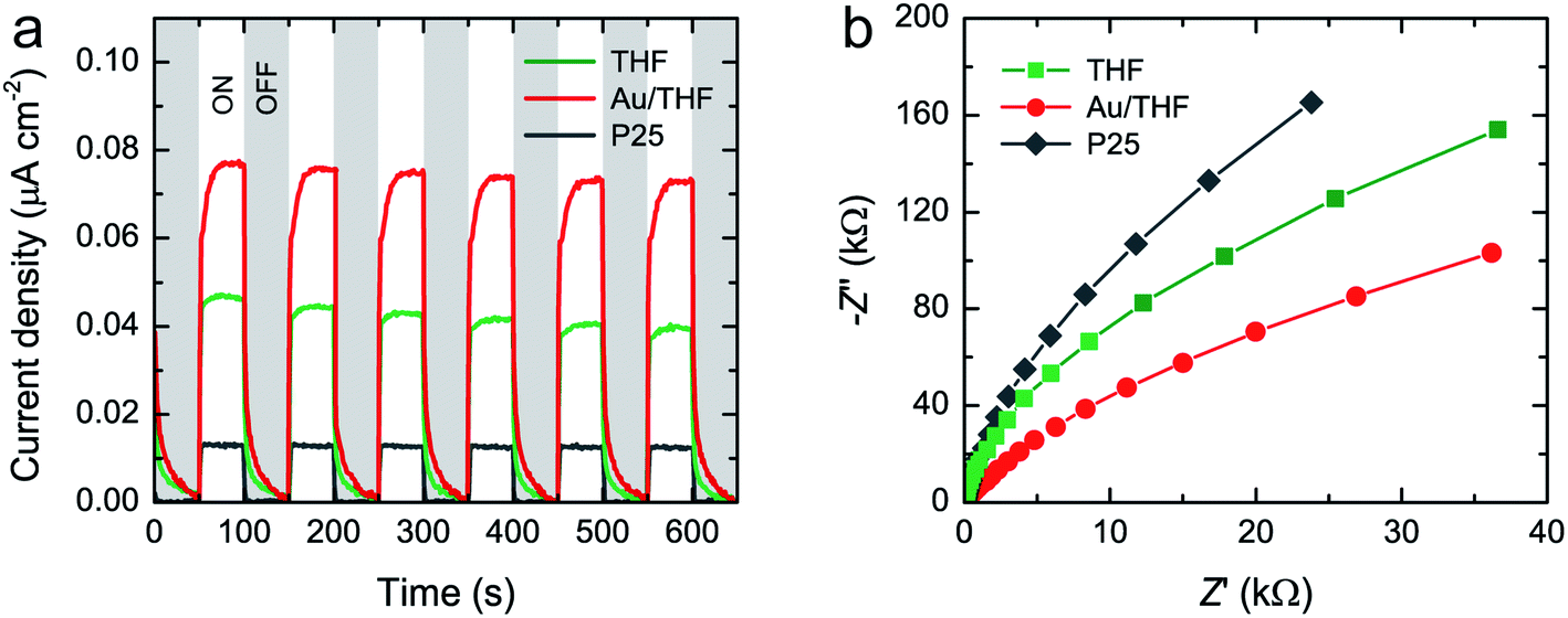 | ||
| Fig. 5 (a) Transient photocurrent density with six on–off cycles and (b) Nyquist plots of THF, Au/THF, and P25 upon Vis-LED irradiation. | ||
The visible-light photocatalytic activity of THF, Au/THF, and P25 was further evaluated by measuring the degradation of MB dye solution (10 mg L−1) under Vis-LED irradiation. The absorbance of MB at 664 nm was measured at different irradiation times to determine the MB degradation (Fig. 6a and S9†). The relative concentrations of MB (C/C0, where C is the MB concentration at irradiation time t, and C0 is the initial MB concentration) in the absence and presence of photocatalysts versus irradiation time are shown in Fig. 6b. In the absence of photocatalysts, the MB solution was self-degraded by 30% under Vis-LED irradiation for 8 h due to photolysis of MB.52 All photocatalysts were stirred in the MB solution under dark conditions for 2 h before the photocatalytic test. The MB absorbance decreased by 1% and 8% for THF and Au/THF, respectively. There was no change in the MB absorbance after 2 h indicating adsorption–desorption equilibrium. In contrast, no MB adsorption was noticed for P25. The degradation of MB under P25 was close to the self-degradation of MB after Vis-LED irradiation for 8 h, indicating its lack of visible-light photocatalytic activity, which is consistent with other previous works.53,54 The MB solution in the presence of THF and Au/THF was degraded by 46% and 88%, respectively. Excluding the self-degradation and adsorption effect, Au/THF possessed a much higher photocatalytic activity than THF. Furthermore, the kinetic reaction analysis of MB degradation over THF and Au/THF was found to follow the pseudo-first-order kinetic reaction (−ln(C/C0) = kt, where k is the pseudo-first-order rate constant, and t is irradiation time). The k value was calculated from the slope of a linear fitting line as shown in Fig. 6c. The k value of Au/THF was 19.98 × 10⁻² h−1, which is about three-fold greater than that of THF (7.53 × 10⁻² h−1). The photocatalytic results showed a similar tendency according to the PL, photocurrent and EIS measurements. It suggests that the Au/THF exhibited good visible-light photocatalytic activity under Vis-LED irradiation.
 | ||
| Fig. 6 (a) Representative absorption spectra of MB solution at various Vis-LED irradiation times in the presence of Au/THF. (b) The plot of C/C0 versus irradiation time of THF, Au/THF, and P25. (c) The plot of −ln(C/C0) versus irradiation time for THF, Au/THF, and P25. (d) Recyclable photocatalytic test of Au/THF over four cycles. | ||
In association with the overall characterization results, despite the same band gap for THF and P25, the MB degradation rate of THF was much higher than that of P25. This confirmed the advantage of a hollow structure in enhancing photocatalytic activity. The remarkable enhancement of photocatalytic activity for Au/THF could reasonably be attributed to the combination of several effects. (i) Multiple-light scattering and reflection within the hollow cavity of THF could enhance the light-harvesting efficiency involved in the photocatalysis process.21–23 (ii) A larger surface area and mesoporous wall of THF could provide more accessible surface sites for MB adsorption and degradation by photocatalysis reaction.38,39 It also facilitated mass exchange between MB molecules and degraded products over the Au/THF surface. (iii) Low charge transfer resistance could facilitate charge separation, thus increasing electrons and holes or inhibiting recombination in the photocatalytic reaction.51 (iv) The presence of more hydroxyl group at the surface could generate more ˙OH and also enhance hydrophilicity, which accounts for enhanced photocatalytic activities.55–57 (v) Au/THF could absorb visible-light from Vis-LED due to the SPR of AuNPs. The photoexcited electrons surpass the Schottky junction at the interface between AuNPs and THF. They are then transferred to the CB of THF leaving behind the holes in the AuNPs. The electrons in the CB of THF reacted with O2 to produce superoxide anion radicals (˙O2−) and eventually ˙OH. The holes oxidized the adsorbed H2O or hydroxide anions (OH−) to ˙OH.16,17,44 The formation of ˙OH species can oxidize and subsequently degrade the MB molecules. A schematic illustrating the photogenerated electrons and holes on Au/THF under Vis-LED is depicted in Fig. 7.
 | ||
| Fig. 7 Schematic diagram of the MB photocatalytic degradation on Au/THF under Vis-LED irradiation. | ||
To confirm the reusability of Au/THF, a photocatalytic test was performed for four cycles using a similar procedure. The recycling test confirmed that the MB photocatalytic degradation on Au/THF was slightly decreased by about 9% after four cycles as shown in Fig. 6d. The SEM images of Au/THF after recycling tests showed that it was destructed into short-length fibers and flake-like structure possibly due to the effect of mechanical stirring (Fig. S10†). Another possible cause is the leaching of AuNPs from THF as confirmed by the decrease of Au content according to the EDS analysis (0.42 ± 0.08 at%). There were no changes in the crystalline structure of TiO2 and surface chemical states according to the XRD and XPS analyses (Fig. S11 and S12†). A significant merit of Au/THF is easy to sediment and redisperse in aqueous solution, thus resulting in easy separation and recovery from the treated water (Fig. S13†).
Conclusions
Au/THF was successfully prepared by the template method and SPP. THF exhibited an anatase phase with a hollow structure and mesoporous wall. Well-crystalline AuNPs with a size of about 5–10 nm were evenly distributed on the THF wall surface. Au/THF had excellent visible-light photocatalytic activity towards MB degradation under Vis-LED. This could be attributed to several effects including effective light-harvesting by a hollow structure, a large surface area with a mesoporous wall of THF, and visible-light absorption and efficient charge separation induced by AuNPs. Moreover, Au/THF was also easy to separate and recover from treated water for reuse. The results obtained in this work suggest that Au/THF could be a potential and alternative photocatalyst for wastewater treatment and related applications under Vis-LED irradiation.Author contributions
Conceptualization: G. P.; data curation: G. P., S. W.; formal analysis: G. P., S. W., C. C.; M. T.; funding acquisition: G. P., O. J.; investigation: G. P., S. W., C. C.; M. T.; methodology: G. P., C. C.; project administration: G. P.; resource: G. P., N. S.; visualization: G. P., M. T.; validation: G. P., O. J., N. S.; writing – original draft: G. P.; writing – review & editing: G. P.Conflicts of interest
There are no conflicts to declare.Acknowledgements
This work was financially supported by Kasetsart University Research and Development Institute (KURDI, grant no. FF(KU) 25.64) and Special Program for Research against COVID-19 (SPRAC), Japan International Cooperation Agency Project for ASEAN University Network/Southeast Asia Engineering Education Development Network (JICA Project for AUN/SEED-Net). S. W. gratefully thanks the research assistant scholarship from the Faculty of Engineering, Kasetsart University (No. 61/06/MET/Innovation).Notes and references
- A. Ajmal, I. Majeed, R. N. Malik, H. Idriss and M. A. Nadeem, RSC Adv., 2014, 4, 37003–37026 RSC.
- Z. Guo, R. Ma and G. Li, Chem. Eng. J., 2006, 119, 55–59 CrossRef CAS.
- S. Kanan, M. A. Moyet, R. B. Arthur and H. H. Patterson, Catal. Rev., 2020, 62, 1–65 CrossRef CAS.
- I. J. Ani, U. G. Akpan, M. A. Olutoye and B. H. Hameed, J. Cleaner Prod., 2018, 205, 930–954 CrossRef CAS.
- J. Schneider, M. Matsuoka, M. Takeuchi, J. Zhang, Y. Horiuchi, M. Anpo and D. W. Bahnemann, Chem. Rev., 2014, 114, 9919–9986 CrossRef CAS PubMed.
- D. Chen, Y. Cheng, N. Zhou, P. Chen, Y. Wang, K. Li, S. Huo, P. Chen, P. Peng, R. Zhang, L. Wnag, H. Liu, Y. Li and R. Ruan, J. Cleaner Prod., 2020, 268, 121725 CrossRef CAS.
- H. Dong, G. Zeng, L. Tang, C. Fan, C. Zhang, X. He and Y. He, Water Res., 2015, 79, 128–146 CrossRef CAS PubMed.
- M. Ikram, E. Umar, A. Raza, A. Haider, S. Naz, A. Ul-Hamid, J. Haider, I. Shahzadi, J. Hassen and S. Ali, RSC Adv., 2020, 10, 24215–24233 RSC.
- B. Guan, J. Yu, S. Guo, S. Yu and S. Han, Nanoscale Adv., 2020, 2, 1352–1357 RSC.
- X. Liu, Y. Shi, Y. Dong, H. Li, Y. Xia and H. Wang, New J. Chem., 2017, 41, 13382–13390 RSC.
- M. Hosseini and A. Valikhani, New J. Chem., 2021, 45, 12464–12470 RSC.
- S. A. Ansari, M. M. Khan, M. O. Ansar and M. H. Cho, New J. Chem., 2016, 40, 3000–3009 RSC.
- S. A. Bakar and C. Ribeiro, RSC Adv., 2016, 6, 36516–36527 RSC.
- X. Chen, L. Liu and F. Huang, Chem. Soc. Rev., 2015, 44, 1861–1885 RSC.
- G. Panomsuwan, A. Watthanaphanit, T. Ishizaki and N. Saito, Phys. Chem. Chem. Phys., 2015, 17, 13794–13799 RSC.
- A. Primo, A. Corma and H. García, Phys. Chem. Chem. Phys., 2011, 13, 886–910 RSC.
- M. R. Khan, T. W. Chuan, A. Yousuf, M. N. K. Chowdhury and C. K. Cheng, Catal. Sci. Technol., 2015, 5, 2522–2531 RSC.
- R. Deas, S. Pearce, K. Goss, Q. Wang, W.-T. Chen and G. I. N. Waterhouse, Appl. Catal., A, 2020, 602, 117706 CrossRef CAS.
- Y. Gao, X.-B. Fan, W.-F. Zhang, Q.-S. Zhao, G.-L. Zhang, F.-B. Zhang and Y. Li, Mater. Lett., 2014, 130, 1–4 CrossRef CAS.
- J. Lu, P. Zhang, A. Li, F. Su, T. Wang, Y. Liu and J. Gong, Chem. Commun., 2013, 49, 5817–5819 RSC.
- M. Samadpour, S. Gilmenez, A. I. Zad, N. Taghavinia and I. Mora-Sero, Phys. Chem. Chem. Phys., 2012, 14, 522–528 RSC.
- X. Zou, Y. Yang, H. Chen, X.-L. Shi, G. Suo, X. Ye, L. Zhang, X. Hou, L. Feng and Z.-G. Chen, J. Colloid Interface Sci., 2020, 579, 463–469 CrossRef CAS PubMed.
- M. Rahman, F. Tajabadi, L. Shooshtari and N. Taghavinia, ChemPhysChem, 2011, 12, 966–973 CrossRef CAS PubMed.
- G. Li, C. Liu and Y. Liu, J. Am. Ceram. Soc., 2007, 90, 1283–1285 CrossRef CAS.
- T. Zheng, Z. Tian, B. Su and Z. Lei, Ind. Eng. Chem. Res., 2012, 51, 1391–1395 CrossRef CAS.
- S. Wongcharoen and G. Panomsuwan, Mater. Lett., 2018, 228, 482–485 CrossRef CAS.
- X. Zhang, D. K. Wang, D. R. S. Lope and J. C. D. Costa, Chem. Eng. J., 2014, 236, 314–322 CrossRef CAS.
- G. Yue, S. Li, D. Li, J. Liu, Y. Wang, Y. Zhao, N. Wang, Z. Cui and Y. Zhao, Langmuir, 2019, 35, 4843–4848 CrossRef CAS PubMed.
- X. Hu, S.-P. Cho, O. Takai and N. Saito, Cryst. Growth Des., 2012, 12, 119–123 CrossRef CAS.
- A. Watthanaphanit, G. Panomsuwan and N. Saito, RSC Adv., 2014, 4, 1622–1629 RSC.
- G. Panomsuwan, T. Ueno, H. Yui, J. Nakamura and N. Saito, in Molecular Technology: Materials Innovation, ed. H. Yamamoto and T. Kato, Elsevier, Amsterdam, 2019, ch. 7, vol. 3, pp. 137–172 Search PubMed.
- M. Zhou, J. Zhang, B. Chang and H. Yu, Int. J. Photoenergy, 2012, 2012, 52843 Search PubMed.
- S. Padikkaparambil, B. Narayanan, Z. Yaakob, S. Viswanathan and S. Tasirin, Int. J. Photoenergy, 2013, 2013, 752605 CrossRef.
- B. Tahir, M. Tahir and N. A. S. Amin, Clean Technol. Environ. Policy, 2016, 18, 2147–2160 CrossRef CAS.
- S. K. Khore, S. R. Kadam, S. D. Naik, B. B. Kale and R. S. Sonawane, New J. Chem., 2018, 42, 10958–10968 RSC.
- V. N. Nguyen, M. V. Nguyen, T. H. T. Nguyen, M. T. Doan, L. L. T. Ngoc, E. Janssens, A. Yadav, P.-C. Lin, M. S. Nguyen and N. H. Hoang, Catalysts, 2020, 10, 261 CrossRef CAS.
- M. Thommes, K. Kaneko, A. V. Neimark, J. P. Olivier, F. Rodriguez-Reinoso, J. Rouquerol and K. S. W. Sing, Pure Appl. Chem., 2015, 87, 1051–1069 CAS.
- T. Fröschl, U. Hörmann, P. Kubiak, G. Kučerová, M. Pfanzelt, C. K. Weiss, R. J. Behm, N. Hüsing, U. Kaiser, K. Landfester and M. Wohlfahrt-Mehrens, Chem. Soc. Rev., 2012, 41, 5313–5360 RSC.
- W. Zhou and H. Fu, ChemCatChem, 2013, 5, 885–894 CrossRef CAS.
- W. Haiss, N. T. K. Thanh, J. Aveyard and D. G. Fernig, Anal. Chem., 2007, 79, 4215–4221 CrossRef CAS PubMed.
- D. Arockia Jency, R. Parimaladevi and M. Umadevi, J. Cluster Sci., 2018, 29, 793–804 CrossRef CAS.
- M. Perera, L. A. Wijenayaka, K. Siriwardana, D. Dahanayake and K. M. Nalin de Silve, RSC Adv., 2020, 10, 29894 Search PubMed.
- N. T. T. Thuy, D. H. Tung, L. H. Manh, J. H. Kim, S. I. Kudryashov, P. H. Minh and N. T. Hien, Appl. Sci., 2020, 10, 3345 CrossRef CAS.
- S. K. Khore, S. R. Kadam, S. D. Naik, B. B. Kale and R. S. Sonawane, New J. Chem., 2018, 42, 10958–10968 RSC.
- F. Su, T. Wang, R. Lv, J. Zhang, P. Zhang, J. Lu and J. Gong, Nanoscale, 2013, 5, 9001–9009 RSC.
- J. Choi, P. Sudhagar, P. Lakshmipathiraj, J. Woo Lee, A. Devadoss, S. Lee, T. Song, S. Hong, S. Eito, C. Terashima, T. H. Han, J. K. Kang, A. Fujishima, Y. S. Kang and U. Paik, RSC Adv., 2014, 4, 11750–11757 RSC.
- N. T. Sahrin, R. Nawaz, C. F. Kait, S. L. Lee and M. D. H. Wirzal, Nanomaterials, 2020, 10, 128 CrossRef CAS PubMed.
- A. Bahraman and D. D. Dionysiou, J. Photochem. Photobiol., A, 2020, 403, 112868 CrossRef.
- N. Kruse and S. Chenakin, Appl. Catal., A, 2011, 391, 367–376 CrossRef CAS.
- F. Xu, J. Mei, M. Zheng, D. Bai, D. Wu, Z. Gao and K. Jiang, J. Alloys Compd., 2017, 693, 1124–1132 CrossRef CAS.
- J. Ângelo, P. Magalhães, L. Andrade and A. Mendes, Appl. Surf. Sci., 2016, 387, 183–189 CrossRef.
- A. Sáenz-Trevizo, P. Pizá-Ruizl, D. Chávez-Flores, J. Ogaz-Parada, P. Amézaga-Madrid, A. Vega-Ríos and M. Miki-Yoshida, J. Fluoresc., 2019, 29, 15–25 CrossRef PubMed.
- W. Li, R. Liang, A. Hu, Z. Huang and Y. Norman Zhou, RSC Adv., 2014, 4, 36959–36966 RSC.
- C. Zhang, Y. Ma, C. Li, F. Qin, C. Hu, Q. Hu and S. Duo, J. Mater. Sci., 2020, 55, 3181–3194 CrossRef CAS.
- J. Wang, X. Liu, R. Li, P. Qiao, L. Xiao and J. Fan, Catal. Commun., 2012, 19, 96–99 CrossRef CAS.
- W. Li, D. Du, T. Yan, D. Kong, J. You and D. Li, J. Colloid Interface Sci., 2015, 444, 42–48 CrossRef CAS PubMed.
- C.-Y. Wu, J. P. Deng and C.-H. Wu, Materials, 2017, 10, 566 CrossRef PubMed.
Footnote |
| † Electronic supplementary information (ESI) available. See DOI: 10.1039/d1ra07323k |
| This journal is © The Royal Society of Chemistry 2022 |