 Open Access Article
2D graphene/FeOCl heterojunctions with enhanced tribology performance as a lubricant additive for liquid paraffin†
Mengxin Xie a,
Bingli Pan*ab,
Ning Lia,
Shuang Zhao*a,
Junjiang Yana,
Shihao Guoa,
Zhe Chena and
Honggang Wang
 *c
*c
aInstitute of Henan Polymer Composites, School of Chemical Engineering, Henan University of Science and Technology, 471000 Luoyang, PR China. E-mail: blpan@haust.edu.cn
bNational United Engineering Laboratory for Advanced Bearing Tribology, Henan University of Science and Technology, 471000 Luoyang, PR China
cState Key Laboratory of Solid Lubrication, Lanzhou Institute of Chemical Physics, Chinese Academy of Sciences, Lanzhou, 730000, PR China
First published on 20th January 2022
Abstract
The purpose of this study is to prepare graphene/FeOCl (G/FeOCl) heterojunctions via a microwave-pyrolysis approach and probe into the synergistic lubrication of G with FeOCl in liquid paraffin (LP). The morphology and chemical composition of specimens were analysed by utilizing scanning electron microscopy (SEM) with energy dispersive spectroscopy (EDS), X-ray diffraction (XRD), Fourier transform infrared (FTIR) spectroscopy, and X-ray photoelectron spectroscopy (XPS) techniques. The tribological property of G/FeOCl was determined, and the interaction between the G/FeOCl heterojunction and friction pair was carried out through simulation calculations. The results indicated that neither G nor FeOCl significantly improved the lubrication performance of LP. However, together with FeOCl, G as lubrication additives greatly improved the lubrication performance of LP. Under the load of 1.648 GPa, the mean friction coefficient and wear scar diameter of LP containing 0.20 wt% G/FeOCl were 66.1% and 44.7% inferior to those of pure LP, respectively. Scanning electron microscopy (SEM) and elemental mapping analyses of worn scars revealed the formation of G/FeOCl layer tribofilms that prevent direct contact between metals. In addition, the high interfacial energy between graphene and FeOCl calculated based on first-principles density functional theory (DFT) further confirmed that graphene and FeOCl simultaneously form friction films with wear resistance and wear reduction effect at the friction interface, which is consistent with the experimental results. This study, therefore, provides a pathway for low-friction lubricants by deploying G/FeOCl two-dimensional material systems.
1. Introduction
About 20% of the total energy production in the world is used to overcome friction. As mobility continues to increase, these numbers will no doubt skyrocket, posing huge challenges for sustainable transport.1–3 Therefore, reducing friction and wear can not only improve the service life of machinery but also improve the energy efficiency. Lubricants are thought to reduce friction and wear by forming a stable lubricating film between the surfaces of the friction pairs. However, the potential of lubricant depends on factors such as additive concentration, composition, and molecular structure.4 Among them, the molecular structure is particularly significant.Recent trends in nanoscale additives and their derivatives have led to a proliferation of studies on two-dimensional nanomaterials with improved anti-wear and anti-friction behaviours.5 With excellent mechanical properties, outstanding electrical and thermal conductivity, specific surface area, remarkable self-lubricating properties and superior thermal conductivity, graphene offers unique and interesting possibilities for structural and mechanical applications, making it stand out among 2D lubricating materials.6,7 Furthermore, the weak van der Waals interlaminar forces between adjacent layers of G and intrinsically low adhesion enable easy lamellar shear and make it to prevent wear between contact surfaces in the process of mutual motion.8,9 The ability of G to inhibit wear is due in part to its mechanical strength; Young's modulus of the order 1 TPa is equivalent to the in-plane elastic stiffness of G.10,11 Inspired by these superiorities, sizeable efforts have been put into excavating graphene-based composites as nanoadditives to boost the antifriction and antiwear properties of base oils.12 For instance, Tan et al. found that nanoporous graphite can significantly improve the wear resistance of phenolic resin.13 Zhao et al. adopted the exfoliation method to inquire into the effect of different layer numbers and layer spacing on the performance of graphene as lubrication additive and drew a conclusion that the degree of exfoliation is pivotal in the structural evolution of graphene, that is, highly exfoliated graphene indeed reaching interlayer slip, which can achieve superior lubrication.14 Han et al. reported that imidazolyl dinitrile salt modified graphene improved the tribological and wear properties of PEG200, and the lubrication effect was derived from the protective layer formed on the friction pair interface by the modified graphene.15 However, there are fewer functional groups on the surface of G, so the adhesion ability on the surface of the friction pair is weak. In addition, there are some challenges in improving the service life and carrying capacity of G. Heterostructures assembled from different two-dimensional materials obviously provide us with more possibilities to adjust the interface conditions and obtain specific properties we need.
Zhang et al. demonstrated that RGO/Fe3O4 could significantly improve the tribological properties of PAO6 due to the synergistic effect of RGO and Fe3O4.16 Li et al. confirmed that graphene–Fe3O4 could enhance the binding between resin and fiber and improve its tribological properties.17 Therefore, compounds containing iron are considered to have good friction lubrication potential. Iron oxychloride (FeOCl) is a self-stacking layer of oxygen halide formed by van der Waals forces. FeOCl as a functional material has attracted more and more attention for the past few years. Furthermore, the specific layer structure of FeOCl can promote electron transfer.18 As is known, all compounds with layered structures are brilliant adsorption materials.19 Nonetheless, FeOCl has a low band gap energy (about 1.8 eV), resulting in rapid carrier recombination. It has been reported that a possible way to improve the environmental stability of FeOCl is to structure a heterogeneous system with other materials.20 Unfortunately, to the best of our knowledge, there have been no reports on the tribological properties of FeOCl.
Consequently, this study attempted to introduce G as a substrate to afford abundant attachment sites for FeOCl. On the basis of giving full play to the prominent adsorption properties of G and FeOCl, it is hoped that the incommensurate combination of G and FeOCl can further enhance the frictional properties. In this paper, a two-step simple microwave-pyrolysis approach for the synthesis of G/FeOCl heterojunctions was presented. Samples characterization results based on a scanning electron microscope (SEM) with EDS, X-ray diffractometer (XRD), Fourier transform infrared (FTIR), and X-ray photoelectron spectroscopy (XPS) analyses confirmed the successful synthesis of G/FeOCl heterojunctions. The tribo-performance of G/FeOCl heterojunctions as an additive to LP was probed using the four-ball friction machine. Field emission scanning electron microscopy (FESEM), and elemental mapping analysis were used to analyze the worn scars on the surface of the steel ball to understand the lubrication mechanism and action of friction and wear of G/FeOCl in LP. Furthermore, the interfacial energy between G and FeOCl was calculated via DFT, and the simulation results verified the conjectured mechanism of the experiment.
2. Materials and methods
2.1 Materials
Citric acid (C6H8O7·H2O, ≥99.5%, Tianjin Fengchuan Chemical Reagent Technologies Co., Ltd.), iron trichloride (FeCl3·6H2O, ≥99.0%, Damao Chemical Reagent Factory), octadecylamine (C18H39N, ≥90.0%, Shanghai Jingchun Reagent Co., Ltd.) and N,N′-dicyclohexylcarbodiimide (C13H22N2, ≥90.0%, Shanghai Macklin, Biochemical Co., Ltd.) were used as received without further purification. Acetone (CH3COCH3, ≥99.5%, Luoyang Haohua Chemical Reagent Co., Ltd.), liquid paraffin received from Tianjin Deen Chemical Reagent Corporation Limited, was used as lube base oil. All chemical reagents were used directly without further purification.2.2 Preparation of G/FeOCl heterojunction
Graphene was synthesized by pyrolysis of citric acid in the light of the literature method.21 A microwave-pyrolysis approach was applied to the preparation of G/FeOCl composites. In the first step, the crucible containing FeCl3·6H2O was sealed and kept in a microwave oven at low heat for 10 minutes. Afterward, the resulting reddish-brown FeOCl was slowly cooled to room temperature and ground into a powder. Due to the high solubility of ferric chloride in acetone, the product was cleaned with acetone to remove unreacted ferric chloride and to prevent the formation of ferric divalent. In the second step, FeOCl was mixed with citric acid at the mass ratio of 1![[thin space (1/6-em)]](https://www.rsc.org/images/entities/char_2009.gif) :
:![[thin space (1/6-em)]](https://www.rsc.org/images/entities/char_2009.gif) 10 in a beaker under grinding evenly. Subsequently, the beaker containing the powder was sealed with polyimide tape, in which holes were punched, and carefully placed in an oven at 180 °C for pyrolysis for 30 minutes. After completion of pyrolysis, the acquisition was ground again after taking out and was separated by centrifugation. The product was repeatedly washed with acetone to remove the unspent reaction precursor and dried under vacuum at 80 °C.22 Finally, the dark grey colored G/FeOCl heterojunction, was obtained.
10 in a beaker under grinding evenly. Subsequently, the beaker containing the powder was sealed with polyimide tape, in which holes were punched, and carefully placed in an oven at 180 °C for pyrolysis for 30 minutes. After completion of pyrolysis, the acquisition was ground again after taking out and was separated by centrifugation. The product was repeatedly washed with acetone to remove the unspent reaction precursor and dried under vacuum at 80 °C.22 Finally, the dark grey colored G/FeOCl heterojunction, was obtained.
2.3 Material characterizations
The phase structure of the as-prepared product was identified using a Bruker D8 advance X-ray diffractometer (XRD, range, 5–80°; scan rate, 5° min−1). FTIR spectra of graphene-based samples were measured using Fourier transform infrared spectrometry (IRTracer-100) for detecting the chemical structure of powder samples. X-ray photoelectron spectroscopy (XPS) was conducted on PerkinElmer PHI-5300 ESCA to identify the chemical states and coordination environment of Fe in the product. The morphologies and images of the samples were captured using a scanning electron microscope (SEM). Energy-dispersive X-ray spectrometry (EDS) was used for qualitative chemical analyses.2.4 Computational methods
First-principles calculations were performed using the DFT method, which enabled structural optimization of G/FeOCl model and computations of energy, as implemented in the Dmol3 code inlaid in the Material Studio software (Accelrys, SanDiego, CA).23 Particularly, the exchange–correlation functional was depicted by the Generalized Gradient Approximation (GGA) of the Perdew–Burke–Ernzerhof (PBE), and a double numerical plus polarisation (DNP) basis set.24 DFT Semi-core pseudopots (DSPP) was employed in core electronic treatment.25,26 A 2 × 2 × 2 Monkhorst–Pack mesh was selected for sampling k-points in Brillouin region. Parameter settings in the simulation are shown in Table 1. The calculated energies were coordinated by a dispersion correction on the basis of the Tkatchenko and Scheffler methods (i.e., a van der Waals DFT-D functional).27 Furthermore, graphene was framed based on the C48H18 clusters (Fig. S1†), which was a simplified model to bring down the difficulty and complexity of calculation. The model of FeOCl was constructed based on the research of predecessors.28 The value of the adsorption energy (Eads) was calculated via the following formula:| Eads = EG+FeOCl − EG − EFeOCl | (1) |
In the above formula, EG, EFeOCl and EG+FeOCl represent the energy of the graphene, the energy of the FeOCl molecule and the total energy of FeOCl adsorbed on the graphene surface, respectively. Negative adsorption energy is advantageous in energy.
2.5 Tribo-performance evaluation
An MM-W1 four-ball vertical universal friction test system controlled by a microcomputer (Jinan Puye Electromechanical Technology Co., Ltd, Jinan, China) was used to probe the tribological properties of prepared samples as a lubricating additive to liquid paraffin oils as per GB3142-82 and ASTM5183-95 standards. The friction and wear tests were carried out under 1.648 GPa and 1000 rpm for 30 min test duration. Steel balls, which are composed of GCr15 bearing steel (hardness: 61–66 Hardness Rockwell C (HRC), and diameter: 12.7 mm) were used in this work. Pre- and post-cleaning of the balls was performed using acetone by ultra-sonication followed by drying. Three replicate friction and wear tests were conducted under a preset condition so as to minimize data scattering. At the end of each test, the wear scar diameter (WSD) of each of the three lower stationary balls was measured by the image acquisition system (±0.01 mm) of the four-ball tester. The average WSD of three lower balls was calculated and reported in this paper. After the wear test, the morphologies of the worn surfaces were detected using SEM, and chemical compositions of the wear scar surfaces were analyzed by elemental mapping.3. Results and discussion
3.1 Structural and morphological features of lubricant additive
SEM images of FeOCl, G, and G/FeOCl heterojunction are displayed in Fig. 1a–c, respectively. From the magnified SEM image (Fig. 1a), it can be seen that FeOCl was composed of a great many ruleless plates, and the interlayer interface was not visible.22 Fig. 1c perspicuously revealed FeOCl garnishing G sheet, and the size of the binary hybrid was obviously smaller than that of a single component, presenting a lamellar structure with stacked nanosheets.29 The chemical composition of G/FeOCl was obtained from its mapping and EDS spectrum (Fig. 1d). Signals due to carbon, oxygen, and ferrum along with chlorine were clearly visible in the spectrum, indicating the formation of the proposed heterojunction. The embedded atom distribution and atomic weight% data in Fig. 1d reflected the formation of the G/FeOCl heterojunction. | ||
| Fig. 1 SEM images of (a) FeOCl, (b) G, (c) G/FeOCl and (d) the mapping and the EDS spectrum of G/FeOCl. | ||
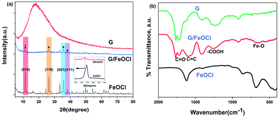
The XRD patterns of the synthesized FeOCl and G/FeOCl are shown in Fig. 2a. The obvious characteristic diffraction peaks of FeOCl and G/FeOCl were located at 11.43, 26.41, 35.78 and 38.23 corresponding to (010), (110), (021), and (111) crystal facets, respectively. These findings can be assigned to the pure phase of FeOCl as per orthorhombic lattice, JCPDS no. 24-1005 and JCPDS no. 72-0619.30 The (010), (110), and (021) peak intensities of G/FeOCl were significantly weaker than that in FeOCl, which was caused by the effect of G embedded in the FeOCl lattice on both sides of the crystallites, thus reducing the size of G/FeOCl, which was consistent with the results of SEM measurements.
FT-IR spectrum was used to reveal the successful synthesis of the G/FeOCl hybrid. The FTIR spectrum (Fig. 2b) of G/FeOCl displays the presence of C![[double bond, length as m-dash]](https://www.rsc.org/images/entities/char_e001.gif) O (1716 cm−1), C
O (1716 cm−1), C![[double bond, length as m-dash]](https://www.rsc.org/images/entities/char_e001.gif) C (1610 cm−1), –COOH (1269 cm−1) and Fe–O (636 cm−1).29,31 The typical functional groups of GO can be seen in the FT-IR of heterojunctions, indicating the successful composite of G and FeOCl.
C (1610 cm−1), –COOH (1269 cm−1) and Fe–O (636 cm−1).29,31 The typical functional groups of GO can be seen in the FT-IR of heterojunctions, indicating the successful composite of G and FeOCl.
In order to verify the chemical structure of G/FeOCl heterozygote, XPS measurements were used to investigate both FeOCl and G/FeOCl. The full-range XPS spectrum of the heterozygote (Fig. 3e) clearly shows the photoelectron peak signals of Fe, Cl, O and C, with atomic% of 5.79, 2.04, 30.77, and 61.40, respectively, which further verifies that G and FeOCl coexist in the heterojunction. The core-level spectrum after optimal fitting parameter deconvolution based on Thermo Avantage software is shown in Fig. 3. Fig. 3a clearly exhibits core-level spectra of C 1s deconvoluted into four peaks with binding energies of 284.6, 285.7, 287.8, and 288.9 eV corresponding to C–C, C–O, C![[double bond, length as m-dash]](https://www.rsc.org/images/entities/char_e001.gif) O, and O–C
O, and O–C![[double bond, length as m-dash]](https://www.rsc.org/images/entities/char_e001.gif) O bonds, respectively.32 Fig. 3b shows the O 1s spectrum of G/FeOCl composite material. The oxygen in G/FeOCl material was mainly decomposed into two peaks, which were similar to the peaks of FeOCl in Fig. S1c.† The peak at 530.8 eV matched Fe–O in the FeOCl lattice while the peak at 532.6 eV was attributed to adsorbed oxygen on the surface.33,34 Fig. 3c shows core-level spectra of Cl 2p deconvoluted into two distinct peaks at 197.1 eV and 198.8 eV, which belong to Cl 2p of Cl in G/FeOCl heterozygote.35 Compared with the Cl 2p peak of FeOCl (Fig. S1a†), the Cl 2p peak of G/FeOCl moved to a higher level, which was the result of the interaction between G and Cl.29 The peaks of Fe 2p in FeOCl (Fig. S1b†) were centered at 711.7 eV and 725.5 eV, corresponding to the spin–orbit peaks of Fe 2p3/2 and Fe 2p1/2, respectively, indicating that Fe element appears in the Fe(III) state.36 The Fe 2p peaks (710.4 eV and 723.8 eV) of G/FeOCl shifted towards a lower direction than that of FeOCl (Fig. 3d), which was the result of the interaction between FeOCl and G.29,37 The XPS spectra of G/FeOCl further confirmed the successful heterozygosity of FeOCl and G.
O bonds, respectively.32 Fig. 3b shows the O 1s spectrum of G/FeOCl composite material. The oxygen in G/FeOCl material was mainly decomposed into two peaks, which were similar to the peaks of FeOCl in Fig. S1c.† The peak at 530.8 eV matched Fe–O in the FeOCl lattice while the peak at 532.6 eV was attributed to adsorbed oxygen on the surface.33,34 Fig. 3c shows core-level spectra of Cl 2p deconvoluted into two distinct peaks at 197.1 eV and 198.8 eV, which belong to Cl 2p of Cl in G/FeOCl heterozygote.35 Compared with the Cl 2p peak of FeOCl (Fig. S1a†), the Cl 2p peak of G/FeOCl moved to a higher level, which was the result of the interaction between G and Cl.29 The peaks of Fe 2p in FeOCl (Fig. S1b†) were centered at 711.7 eV and 725.5 eV, corresponding to the spin–orbit peaks of Fe 2p3/2 and Fe 2p1/2, respectively, indicating that Fe element appears in the Fe(III) state.36 The Fe 2p peaks (710.4 eV and 723.8 eV) of G/FeOCl shifted towards a lower direction than that of FeOCl (Fig. 3d), which was the result of the interaction between FeOCl and G.29,37 The XPS spectra of G/FeOCl further confirmed the successful heterozygosity of FeOCl and G.
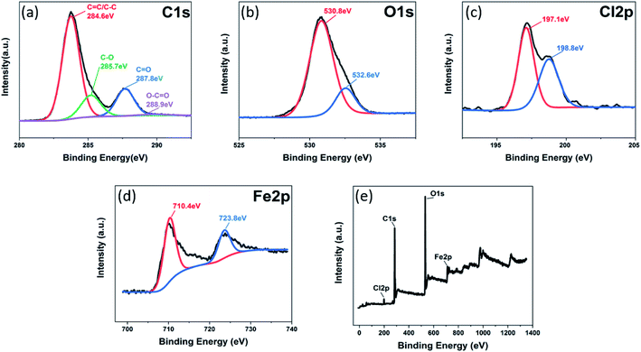 | ||
| Fig. 3 XPS images of G/FeOCl heterozygote: (a) C 1s core-level spectra, (b) O 1s core-level spectra, (c) Cl 2p core-level spectra, (d) Fe 2p core-level spectra, and (e) XPS survey spectra. | ||
3.2 Assessment of tribological behaviour of lubricant additives in LP
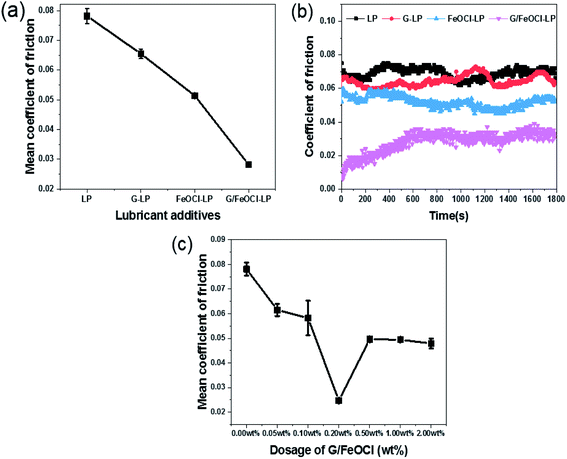
Subsequently, the tribology performance of LP with different concentrations of G/FeOCl heterozygote (from 0.00 wt% to 2.00 wt%) was performed (Fig. 5c). The MCOF decreased with the dose of G/FeOCl increased from 0.00 wt% to 0.20 wt% in LP, it was obviously observed that the COF decreased gradually from 0.078 to 0.027, which was the lowest among all the concentrations. Subsequently, as the concentration of G/FeOCl heterozygote increased from 0.20 wt% to 2.00 wt%, the COF value of LP increased finally reaching 0.049. These results explicitly suggested that with the change in the G/FeOCl heterozygote addition concentration in LP, the optimal concentration was 0.20 wt% for the antifriction performance, and the corresponding MCOF decreased to 0.027. This may be due to the saturation of the contact area between the friction pairs with lubricating additives when the boundary lubrication state was dominant.38 In the case of friction coefficient analysis of graphene lubrication additives, the COF reported by Varrla et al. decreased from 0.10 to (base oil) to 0.02 (0.02 wt% graphene).42 The friction coefficient of graphene-based composites studied by Yang et al. decreased from 0.104 of pure paraffin oil to 0.08 (including 0.50 wt% graphene-based composites).31 In this case, a concentration of 0.20 wt% can help the additive fill the valley in the concave–convex body, thereby reducing COF.
The significant decrease in MCOF value after the addition of the above additives was directly related to their antifriction performance. This behaviour can be explained by the key role that different additives play in the formation of tribochemical films (in situ), which prevented proximal surface contact and was essential for reducing friction on the proximal surface.3 However, the presence of oxygen-containing functional groups, structural ripples, and high shear resistance due to hydrogen bonding between adjacent atomic layers in G had a negative impact on the tribological properties.43 Thus, the obtained results indicated that CM G/FeOCl had better lubrication performance than G, FeOCl and PM G/FeOCl, which may be due to the synergistic lubricating role of G and FeOCl. The difference in lubrication performance between PM G/FeOCl and CM G/FeOCl heterozygote indicates that the synergistic lubrication effect of G and FeOCl had a close relationship with the microstructure of the heterozygote.44 These atoms or molecules interacted with each other under frictional stress conditions and/or interact with the surface of the interacting steel balls to form a protective film between the friction pairs to prevent direct contact between steel balls.45 An overview of typical graphene composites used as lubricant additives are displayed in Table 2.
| Lubricant details | Tribometer | Conditions | Tribological test results | Ref. | |||||
|---|---|---|---|---|---|---|---|---|---|
| Materials | Concentration | Base oil | Load | Speed | Temperature | Wear reduction, % | Friction reduction, % | ||
| Hydroxyl modified fluorinated graphene | 1 mg mL−1 | Water | Ball-on-disk tribometer | 50 N | 0.05 m s−1 | 25 °C | — | 15% | 47 |
| Graphene | 0.025 mg mL−1 | Engine oil | Four-ball | 392 N | 600 rpm | 75 °C | 33% | 80% | 42 |
| GO/f-CMS | 0.2 wt% | 85W-90 | BOD | 40 N | — | — | 54% | 26% | 48 |
| Cu/Gr | 0.4 wt% | 5W-30 | Ring-liner | 216–307 N | 0.25 m s−1 | — | 25–30% | 26.5–32.6% | 39 |
| Titanate-GO | 0.3 mg mL−1 | PAO10 | Four-ball | 392 N | 1200 rpm | 75 °C | 28.2% | 49.5% | 49 |
| OA–LaF3–GO | 0.5 wt% | Liquid paraffin | Four-ball | 300 N | 1450 rpm | 25 °C | 32% | 21.7% | 50 |
| RGO/MoS2 | 0.02–0.08 wt% | Liquid paraffin | Ball-on-disk | 50 N | 0.04–0.05 m s−1 | — | — | 45% | 51 |
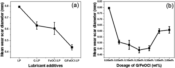 | ||
| Fig. 6 Variation of mean wear scar diameter with (a) different additives; (b) different dosage of G/FeOCl (1.648 GPa, 1000 rpm, 15 min). | ||
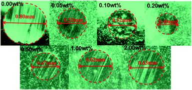
Fig. 6b depicts the change curve of MWSD at different concentrations of G/FeOCl at a load of 1.648 GPa for 15 min in base lube LP. It is clear from Fig. 7b that MWSD values of LP with all concentrations additives were significantly reduced compared to the pure LP. Therefore, G/FeOCl heterojunctions were capable of promoting the wear resistance of LP at each concentration. Fig. 7 portrays digital images of WSD at different G/FeOCl hybrid concentrations. These digital pictures were taken from one of the measurements of the diameter of the wear scar. It can be seen clearly that the WSD of LP containing 0.20 wt% G/FeOCl was the minimum, further demonstrating that its optimal concentration was 0.20 wt%. The LP with 0.20 wt% G/FeOCl exhibited the lowest MWSD (0.44 mm), 44.7% lower than that of pure LP. A further increase dosage of G/FeOCl showed no significant change in the wear resistance. When the concentration of additive was exorbitant, particles tended to agglomerate under the friction-induced effect. The existence of large particles can preclude the small size of G/FeOCl heterojunction from entering the friction zone. Additionally, once large particles are turned into the friction area, it is highly likely that abrasive particles will be formed, increasing friction and thus accelerating surface wear.52 Considering the antifriction and antiwear comprehensively, the optimal concentration of G/FeOCl in LP was 0.20 wt%. The variation trend of the MWSD under different loads and rotating speeds was consistent with the friction coefficient. Under operating conditions, the stable heterostructures were easily transferred and deposited into the contact zone on the surface of the friction pair, forming in situ a tribochemical film with low shear strength, which can resist direct metal-to-metal contact and protect it from friction and wear.53 In fact, G and FeOCl, both of which have layered structures, worked together to improve the efficiency of the composites. The performance of the composites was superior to that of single-component G or FeOCl, which can be explained by the fact that the thermal conductivity of the G/FeOCl hybrid was higher than that of the single component, thereby reducing the local temperature at the metal surface roughness.31 Therefore, heat dissipation provides higher tribological properties.
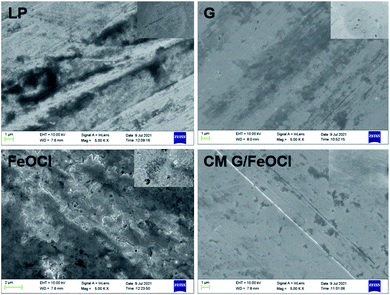
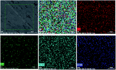
The elemental mapping of the tribofilm formed by the binary heterojunction (G/FeOCl) blended with LP at a loading of 1.648 GPa is shown in Fig. 9, providing information on its elemental composition. The presence of C, O, Fe and Cl elements on the worn steel surface indicates that a tribochemical reaction occurred during sliding. Namely, the G/FeOCl hybrid can easily get into the interface of the friction pair to fill the cracks on the friction surface and prevent direct contact between steel and steel. Simultaneously, the G/FeOCl hybrid was decomposed to form a reactive film to protect the surface of the steel, thus improving the anti-friction and anti-wear ability of LP.44
3.3 Friction and wear mechanism analysis
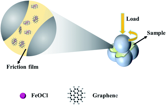
Fig. 10 displays the lubrication mechanism. In view of the above analytical data and discussion, the lubrication mechanism of the significantly improved tribological performance of the G/FeOCl-LP oil lubrication mixture can be interpreted by the interaction of the G/FeOCl heterojunction with the sliding surface. It is well known that the properties of the friction film play a dominant part in the entire efficiency of the additive. Under experimental test conditions with actual load-bearing, the roughness of the steel ball surface permitted G/FeOCl to enter and cling to the proximal surface, forming a friction film in situ, which can bear the load. However, the fabulously excellent performance of the designed binary G/FeOCl heterogeneous material highlighted the synergistic effect between its constituent FeOCl and G. During the lubrication process, FeOCl and G complemented each other by sustaining their layered structure rather than crushing into small particles, and the heterojunction of the layered structure facilitated interlaminar sliding.44 Over time, scratches and grooves, created on the interacting surfaces, were filled with G/FeOCl dispersions. The heat generated by the interface friction caused a tribological chemical reaction that contributes to the formation of a steady tribo-film between the interacting pairs. In order to further prove the friction film formed by FeOCl and G at the friction interface simultaneously, the interaction between graphene and FeOCl was investigated by the first-principles calculation on account of DFT. Fig. S2† portrays the optimized stable structure of graphene adsorption with FeOCl. The value of Eads calculated using formula (1) was −3.64 eV. The negative value of the obtained binding energy indicates that FeOCl tended to adsorb graphene.55 It manifested that physical adsorption existed between FeOCl and graphene. It is confirmed that the friction film was formed by FeOCl and G at the friction interface simultaneously. This friction film served on a third body, namely, the tribo-film formed a protective layer, which reduced the friction and wear on the interface.56 The polishing effect of the studied heterojunction on the worn surface was also considered for improving the lubrication.57 Based on the above mechanism, the prepared G/FeOCl heterojunctions have outstanding tribological properties.4. Conclusions
The deployment of an intercalated composite 2D material system provides a way for graphene to be used as a low friction lubricant. This work has placed forward a newfangled synthesis approach, a fast and efficient microwave-pyrolysis method, to manufacture the G/FeOCl heterojunction with a layered structure, which was applied to a lubrication additive for tribological studies. G/FeOCl has been triumphantly synthesized and characterized using miscellaneous states of the art technologies as per powder XRD, FTIR, XPS, and SEM with EDS mapping. The tribological behaviours of G/FeOCl as the lubricant additives of LP were systematically investigated using a four-ball tribometer under a boundary lubrication regime. It is worth mentioning that the intercalation structure of G/FeOCl played a vital role in regulating its tribological behaviour. At an optimal dosage of 0.20 wt% for G/FeOCl, the average COF and MWSD of LP were reduced by up to 66.1% and 44.7%, respectively. In addition, G/FeOCl shows prominent bearing capacity, long service life and great operation stability, which reflects its huge potential for practical applications. Crucially, the synergistic lubrication effects of graphene and FeOCl were revealed by FE-SEM images, EDS elemental mappings and established as the elementary lubrication mechanism of G/FeOCl as lubricant additives of LP. This work not only provides a universal and feasible approach for preparing graphene-based composites with extraordinary lubricity but also elucidates the synergy of inorganic and organic materials on the boundary lubrication process.Author contributions
Conceptualization, M. X. and B. P.; methodology, M. X., Z. C., and S. G.; software, N. L.; validation, M. X. and B. P.; formal analysis, M. X. and B. P.; investigation, M. X.; resources, B. P.; data curation, M. X.; writing—original draft preparation, M. X.; writing—review and editing, M. X.; visualization, J. Y.; supervision, B. P.; project administration, B. P.; funding acquisition, B. P. All authors have read and agreed to the published version of the manuscript.Conflicts of interest
There are no conflicts to declare.Acknowledgements
The authors sincerely thank the financial support from the National Natural Science Foundation of China (grant number 51675162) and the National SRTP (202110464023).References
- S. Kumari, A. Chouhan, O. P. Sharma, S. Kuriakose and O. P. Khatri, ACS Appl. Mater. Interfaces, 2020, 12, 30720–30730 CrossRef CAS PubMed.
- A. Erdemir, G. Ramirez, O. L. Eryilmaz, B. Narayanan and S. Sankaranarayanan, Nature, 2016, 536, 67–71 CrossRef CAS PubMed.
- D. K. Verma, N. Shukla, B. Kumar, A. K. Singh, K. Shahu, M. Yadav, K. Y. Rhee and R. B. Rastogi, Nanomaterials, 2020, 10, 707 CrossRef CAS PubMed.
- M. Ratoi, V. B. Niste, H. Alghawel, Y. F. Suen and K. Nelson, RSC Adv., 2013, 4, 4278–4285 RSC.
- S. Zhang, T. Ma, A. Erdemir and Q. Li, Mater. Today, 2019, 26, 67–86 CrossRef CAS.
- B. Vasi, A. Matkovi, U. Ralevi, M. Beli and R. Gaji, Carbon, 2017, 120, 137–144 CrossRef.
- Y. Liu, X. Ge and J. Li, Appl. Mater. Today, 2020, 20, 100662 CrossRef.
- D. Berman, A. Erdemir and A. V. Sumant, ACS Nano, 2018, 12, 2122–2137 CrossRef CAS PubMed.
- J. Zhao, B. Pan, Y. Zhang and Y. Zhang, J. Macromol. Sci., Part B: Phys., 2012, 51, 1218–1227 CrossRef.
- G. H. Lee, R. C. Cooper, S. J. An, S. Lee, A. Zande, N. Petrone, A. G. Hammerberg, C. Lee, B. Crawford and W. Oliver, Science, 2013, 340, 1073–1076 CrossRef CAS PubMed.
- M. R. Vazirisereshk, H. Ye, Z. Ye, A. Otero-De-La-Roza and A. Martini, Nano Lett., 2019, 19, 5496–5505 CrossRef CAS PubMed.
- D. Berman, S. A. Deshmukh, S. K. R. S. Sankaranarayanan, A. Erdemir and A. V. Sumant, Science, 2015, 348, 1118–1122 CrossRef CAS PubMed.
- J. Tan, B. Pan, L. Hua, J. Chen, J. Liu, Y. Zhang and Q. Niu, J. Macromol. Sci., Part B: Phys., 2019, 1–11 Search PubMed.
- J. Zhao, J. Mao, Y. Li, Y. He and J. Luo, Appl. Surf. Sci., 2017, 434, 21–27 CrossRef.
- Z. Y. Han, C. L. Gan, X. P. Li, P. Feng, X. L. Ma, X. Q. Fan and M. H. Zhu, Tribol. Int., 2021, 161, 107057 CrossRef CAS.
- Q. Q. Zhang, B. Wu, R. H. Song, H. Song, J. Zhang and X. G. Hu, Tribol. Int., 2020, 141, 105952 CrossRef CAS.
- H. L. Li, L. Jin, J. L. Dong, L. Liu, M. Li, Y. Liu, L. H. Xiao and Y. H. Ao, RSC Adv., 2016, 6, 60200–60205 RSC.
- M. Sun, I. Zucker, D. M. Davenport, X. Zhou, J. Qu and M. Elimelech, Environ. Sci. Technol., 2018, 52, 8674–8683 CrossRef CAS PubMed.
- L. Ai, Y. Zeng and J. Jiang, Chem. Eng. J., 2014, 235, 331–339 CrossRef CAS.
- J. Song, M. Zhang, C. Yan, X. Zhao and J. Zhang, J. Alloys Compd., 2020, 836, 155544 CrossRef CAS.
- Y. Dong, J. Shao, C. Chen, L. Hao, R. Wang, Y. Chi, X. Lin and G. Chen, Carbon, 2012, 50, 4738–4743 CrossRef CAS.
- X. Liu, W. Zhang, L. Mao, Y. Yin and L. Hu, J. Mater. Sci., 2021, 56, 1–15 CrossRef.
- B. Delley, Lett. Nuovo Cimento, 2000, 8, 361–364 Search PubMed.
- J. P. Perdew, K. Burke and M. Ernzerhof, Phys. Rev. Lett., 1998, 77, 3865–3868 CrossRef PubMed.
- M. Shukri, M. Saimin, M. K. Yaakob, M. Yahya and M. Taib, Appl. Surf. Sci., 2019, 494, 817–828 CrossRef CAS.
- S. S. Huang, B. L. Pan, M. X. Xie, J. Y. Gao, G. M. Zhao, Y. M. Niu and H. G. Wang, Tribol. Int., 2020, 154, 106726 CrossRef.
- A. Tkatchenko and M. Scheffler, Phys. Rev. Lett., 2009, 102, 69–72 CrossRef PubMed.
- X. J. Yang, P. F. Tian, X. M. Zhang, X. Yu, T. Wu, J. Xu and Y. F. Han, AIChE J., 2015, 61, 166–176 CrossRef CAS.
- J. Zhang, G. D. Liu and S. Liu, New J. Chem., 2018, 42, 6896–6902 RSC.
- C. Tan, Q. Xu, T. Sheng, X. Cui and H. Li, J. Hazard. Mater., 2020, 398, 123084 CrossRef CAS PubMed.
- C. Yang, X. Hou, Z. Li, X. Li, L. Yu and Z. Zhang, Appl. Surf. Sci., 2016, 388, 497–502 CrossRef CAS.
- V. Jaiswal, K. Kalkhanday, S. Umrao, R. B. Rastogi, R. Kumar and A. Srivastava, ACS Appl. Mater. Interfaces, 2016, 8, 11698–11710 CrossRef CAS PubMed.
- J. Zhao, M. Ji, J. Di, Y. Zhang and J. Xia, J. Photochem. Photobiol., A, 2019, 391, 112343 CrossRef.
- Y. Wang, H. Zhang, Y. Zhu, Z. Dai, H. Bao, Y. Wei and W. Cai, Adv. Mater. Interfaces, 2016, 3, 1500801 CrossRef.
- M. Sabri, A. Habibi-Yangjeh, H. Chang and V. Krishnan, Sep. Purif. Technol., 2020, 250, 117268 CrossRef CAS.
- C. Wan, J. Yue, W. Bao, G. He, Y. Wu and L. Jian, J. Mater. Chem. A, 2019, 7, 9556–9564 RSC.
- J. Zhang, M. Yang, Y. Lian, M. Zhong, J. Sha, G. Liu, X. Zhao and S. Liu, Dalton Trans., 2019, 48, 3476–3485 RSC.
- S. Xiong, B. Zhang, S. Luo, H. Wu and Z. Zhang, Friction, 2020, 1–11 Search PubMed.
- M. K. A. Ali, X. Hou and M. A. A. Abdelkareem, Friction, 2020, 8, 905–916 CrossRef CAS.
- M. Ali, H. Xianjun, L. Mai, C. Qingping, R. F. Turkson and C. Bicheng, Tribol. Int., 2016, 103, 540–554 CrossRef CAS.
- W. Song, P. Chen, J. Yan, W. Zhu and H. Ji, ACS Appl. Mater. Interfaces, 2020, 12, 29737–29746 CAS.
- V. Eswaraiah, V. Sankaranarayanan and S. Ramaprabhu, ACS Appl. Mater. Interfaces, 2011, 3, 4221–4227 CrossRef CAS PubMed.
- A. Chouhan, S. Kumari, S. S. Rawat and O. Khatri, ACS Appl. Mater. Interfaces, 2020, 12, 51785–51796 CrossRef CAS PubMed.
- Y. Xu, Y. Peng, K. D. Dearn, X. Zheng, L. Yao and X. Hu, Wear, 2015, 342, 297–309 CrossRef.
- V. Jaiswal, K. Kalkhanday, S. Umrao, R. B. Rastogi, R. Kumar and A. Srivastava, ACS Appl. Mater. Interfaces, 2016, 11698 CrossRef CAS PubMed.
- P. Wu, X. Chen, C. Zhang, J. Zhang and J. Zhang, Friction, 2020, 9, 143–154 CrossRef.
- L. M. Ma, Z. P. Li, W. H. Jia, K. M. Hou, J. Q. Wang and S. R. Yang, Colloids Surf., A, 2020, 610, 125931 CrossRef.
- Y. Gu, J. Fei, J. Huang, L. Zhang, M. Qu and X. Zheng, Mater. Today Commun., 2020, 25, 101271 CrossRef CAS.
- L. Zhang, X. Sun, X. Liu, Y. He, Y. Chen, Z. Liao, H. Gao and S. Wang, ACS Omega, 2021, 6, 3840–3846 CrossRef CAS PubMed.
- C. Z. Yang, X. Hou, Z. W. Li, X. H. Li, L. G. Yu and Z. J. Zhang, Appl. Surf. Sci., 2016, 388, 497–502 CrossRef CAS.
- K. M. Hou, J. Q. Wang, Z. G. Yang, L. M. Ma, Z. F. Wang and S. R. Yang, Carbon, 2017, 115, 83–94 CrossRef CAS.
- B. Jin, J. Zhao, G. Chen, Y. He and J. Luo, Appl. Surf. Sci., 2021, 546, 149019 CrossRef CAS.
- D. K. Verma, N. Shukla, B. Kumar, A. K. Singh, K. Shahu, M. Yadav, K. Y. Rhee and R. B. Rastogi, ACS Appl. Mater. Interfaces, 2019, 11, 2418–2430 CrossRef CAS PubMed.
- Y. Meng, F. Su and Y. Chen, Chem. Eng. J., 2015, 281, 11–19 CrossRef CAS.
- S. Asaldoust, M. S. Hosseini, B. Ramezanzadeh and G. Bahlakeh, Constr. Build. Mater., 2020, 256, 119439 CrossRef CAS.
- Y. Wu, X. Zeng, T. Ren, E. D. Vries and V. Emile, Tribol. Int., 2017, 105, 304–316 CrossRef CAS.
- I. E. Uflyand, V. A. Zhinzhilo and V. E. Burlakova, Friction, 2019, 7, 93–116 CrossRef.
Footnote |
| † Electronic supplementary information (ESI) available. See DOI: 10.1039/d1ra06650a |
| This journal is © The Royal Society of Chemistry 2022 |

