A self-cleaning hydrophobic MOF-based composite for highly efficient and recyclable separation of oil from water and emulsions

Subhrajyoti Ghosh , Abhijeet Rana , Saurav Kumar , Chiranjib Gogoi , Srijan Mukherjee , Uttam Manna and Shyam Biswas *
Department of Chemistry, Indian Institute of Technology Guwahati, Guwahati, 781039, Assam, India

Received 31st March 2022 , Accepted 8th June 2022

First published on 10th June 2022


Abstract

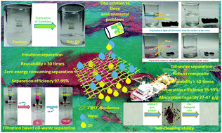
A hydrophobic MOF (1′@CF3) was synthesized by post-synthetic modification to anchor a –CF3 group to the Zr-BDC-OH MOF (1′). The hydrophobic property of the MOF was used for the preparation of a robust hydrophobic composite (1′@CF3@melamine) with melamine sponge. The water contact angle of 1′@CF3@melamine was found to be 145 ± 1°. The hydrophobic composite was demonstrated to separate oil–water mixtures and water-in-oil emulsions even under harsh aquatic environments. The oil–water and emulsion separations were carried out in an easy and fast way without the consumption of energy. The absorption capacity and separation efficiency of the composite for a wide variety of oils were found to be 27–47 g g−1 and 95–99%, respectively. The material showed high recyclability of up to 50 cycles for oil–water separation and for 30 cycles for water-in-oil emulsion separation. In addition, a hydrophobic polymer@1′@CF3-coated glass substrate displayed excellent self-cleaning properties. Furthermore, inexpensive and facile gravity-driven filtration and against gravity-based separation techniques for different oils were developed by employing the composite.

Introduction

The pollution due to oil spills not only ends with water pollution but also affects the nearby land ecosystem and the humidity of air due to changes in evaporation rate and the greenhouse gases released due to the burning of oil.1 The vulnerability caused by the 1991 Gulf war or Ixtoc I oil spills are still in the minds of people.2,3 After every oil spillage, the oil forms a thin layer over water and causes sunlight blockage. The reduced amount of sunlight directly affects the producers of the aquatic food chain and thereby the whole food chain gets affected. The highest vulnerability towards mammals of the seashore, fish nurseries and birds is due to the oil carried by the waves.4 The poisonous and persistent part of oil injected into an organism is transferred to humans by the uptake of seafood.5 The exposure of polycyclic aromatic hydrocarbons of crude oil to the eggs of fishes causes teratogenic effects and premature hatching of eggs.6 Due to the above vulnerable environmental impacts, there is a requirement for an easy oil spill clean-up technique. The traditional methods of oil-spill cleanings, like in situ burning, bioremediation, manual labour, dispersants, etc., are not adequate. In situ burning is not environmentally friendly because of the release of toxic gases.7 In the bioremediation and dispersant method, the oil is not recovered, which is a loss from an economic point of view.8 The use of manual labour requires much time and money. Therefore, the scientific community is searching for an eco-friendly, fast and economical way to settle this issue.

The dispersion of an immiscible liquid in another liquid is known as an emulsion. The emulsion formed by water dispersion in oil is a topic of interest for many scientists. The emulsion formation during crude oil extraction will cause problems if it is not appropriately treated. The presence of water will escalate the corrosion rate of pipes and equipment used during the processing steps. The cost of transporting and pumping speed will increase due to the pressure drop in flowlines.9 Therefore, people are searching for an easy solution to the separation of oil from oil–water emulsions.10

The adhesion of dust and contaminants to the surface of glass, concrete walls, and buildings causes bacterial growth and a foul-smell. A new class of self-cleaning material was first reported by Heller et al. in 1995.11 Afterwards, a few materials with self-cleaning properties were developed to deal with the above issue. Among them, very few numbers of hydrophobic MOFs are utilized for self-cleaning purposes.12,13

All of the above-stated problems have an easy and single solution via hydrophobic-based composite materials. There are many types of hydrophobic materials reported to date.14,15 Among them, very few are MOF-based. The MOF materials are chemically stable and can be functionalized very easily. The porous nature of MOFs has made them famous for gas adsorption and storage, drug delivery and water harvesting purposes.16–18 The wide range of functionality in the family of MOFs makes them unique in the field of sensing and catalysis.19–23 The other absorbent materials like core–shell magnetic materials developed by Yu et al. have very low surface areas, whereas the MOF materials have very large surface areas, which is advantageous for absorption-related applications.24,25 Therefore, we synthesized a Zr(IV) based MOF material (1′@CF3) with a –OCOCF3 group by the post-synthetic modification of Zr-BDC-OH MOF (1′) with trifluoroacetic anhydride. The presence of the –CF3 group is responsible for the development of the hydrophobic nature of 1′@CF3. The powder form of 1′@CF3 does not have freestanding ability. Therefore, we developed a hydrophobic composite (1′@CF3@melamine) by anchoring the MOF powder onto a melamine-coated sponge with the help of a PDMA-co-PMHS polymeric coating. The WCA of the polymer-coated composite without the MOF powder was found to be 106 ± 1°, whereas, for 1′@CF3@melamine, it was 145 ± 1°. The increased WCA value implied that the hydrophobicity in the composite is because of the 1′@CF3 powder. The composite 1′@CF3@melamine was used for the separation of oil from an oil–water mixture using very simple techniques (filtration-based separation, separation in opposition to gravity and absorption-based separation). The composite has a high oil–water separation efficiency (95–99%), which is comparable to those of recent reports on oil–water absorbent materials.26–28 The robust nature of the composite makes it sufficiently recyclable for up to 50 cycles with only 10% decrease in efficiency after the 50th cycle, which is better than the recent reports by Cabello et al.28 and Zhou et al.27 The material was also applied for the separation of oils from water-in-oil emulsions (30 times recyclability) and it was also coated on a glass surface to be used as a self-cleaning material. The absorption capacity of our material ranges from 26 to 37 g g−1, which is higher than the recent reports on oil–water separation by Cabello et al.28 and Liu et al.29 The flux of oil separation from the emulsion was much higher in comparison to the recent reports by Liu et al.29 and Yuan et al.30

Experimental section

Synthesis of Zr-UiO-66-OH (1)

For the synthesis of hydroxyl (–OH)-functionalized Zr-based UiO-66 MOF, we applied the previously reported solvothermal method of synthesis, reported by Katz et al.31 In brief, in a 25 mL Teflon autoclave, 250 mg (1.08 mmol) of ZrCl4, and 197 mg (1.08 mmol) of 2-hydroxyterephthalic acid were taken. After that, 5 mL of DMF and 2 mL of concentrated HCl were added to the previously mentioned solids. After homogeneous mixing of all the components for 15 min via sonication, the mixture was kept in a pre-heated hot air oven at 120 °C for 24 h. Then, the autoclave was gently allowed to come to room temperature and a white coloured product was collected after washing with acetone several times. Then, the white powder was dried in a 100 °C oven. The obtained yield of 1 was 28 mg (0.01 mmol, 76%). ATR-IR (cm−1): 3316 (br), 1574 (s), 1491 (vs), 1412 (vs), 1368 (sh), 1237 (vs), 1158 (w), 961 (w), 773 (vs), 716 (vs), 663 (vs), 572 (m), 488 (w).

Activation of 1

The as-prepared MOF may contain some unreacted starting materials and solvent molecules inside the pores of its framework. To remove such impurities, 1 was stirred in MeOH for 24 h and afterwards, it was recovered by filtration and dried. Then, the dry MOF was heated under a vacuum for another day. Thus, we obtained completely solvent-free, pure Zr-UiO-66-OH MOF called 1′.

Post-synthetic modification of 1′

To functionalize the free hydroxyl (–OH) groups of 1′ by –COCF3 groups, 100 mg (0.06 mmol) of 1′ was placed in 20 mL of dry DCM inside a 50 mL round bottom flask. After the addition of 80 μL of trifluoroacetic anhydride, the reaction medium was stirred (0.6 mmol) for 12 h under ambient conditions (Scheme S1, ESI). After 12 h, the MOF material was filtered and washed with DCM three times. Finally, it was allowed to dry at 60 °C for 4 h. The 1H NMR and 13C NMR spectra after digestion of the modified MOF were collected to determine the post-synthetic modification percentage. From the 1H NMR integration, it was observed that around 67% of the parent MOF was converted to –OCOCF3-functionalized Zr-UiO-66 MOF (Fig. S1, ESI). Hereafter, this post-modified MOF will be called 1′@CF3. 1H NMR (400 MHz, DMSO-d6): δ = 7.94 (d, 1H), 7.88 (d, 0.48H), 7.49 (m, 1.62H), 7.43 (m, 0.96H) ppm. 13C NMR (100 MHz, DMSO-d6): δ = 171.50, 167.81, 166.85, 162.87, 160.96, 159.42, 159.04, 158.67, 158.29, 137.32, 133.30, 131.18, 131.14, 129.70, 129.00, 119.99, 118.14, 117.24, 117.04, 114.17, 111.30 ppm. 19F NMR (400 MHz, DMSO-d6): −75.18 ppm. ESI-MS (m/z): 277.0665 for (M–H) ion (M = mass of H2BDC-OCOCF3 linker) and m/z = 181.0165 corresponds to the mass of H2BDC-OH linker (Fig. S1–S4, ESI). The appearance of a peak at 1202 cm−1 after post-synthetic modification was due to the C–F bond stretching (Fig. S9, ESI).32

Preparation of the 1′@CF3@melamine composite

For the synthesis of the composites of 1′@CF3 with a melamine sponge, at first, the commercially available melamine sponge was cut into small pieces (with a volume of 1 × 1 × 1 cm3) and the sponges were sonicated with acetone for 15 min to remove the unwanted substrates present in the sponges. After that, the sponges were dried in a 50 °C oven for 2 h and a coating of PDA was made on the dry and clean sponges. For that, 80 mg of dopamine hydrochloride was added to a mixture of water and ethanol (volume ratio of water and ethanol was 1[thin space (1/6-em)]:[thin space (1/6-em)]1). Afterwards, 40 mL of 10 mM Tris-buffer solution was added to the previously maintained mixture and the final pH of the medium was adjusted to 8.5 by the addition of an aqueous solution of NaOH. Then, 10 small pieces of sponge (volume of 1 × 1 × 1 cm3) were added to the mixture and they were stirred for 24 h. After 24 h, black coloured PDA coated melamine sponges were obtained, which were washed with water and dried for 12 h in an 80 °C oven.

A cross-linked polymeric solution was obtained after mixing PDMS and PMHS in the presence of the catalyst, dibutyltin dilaurate. For the preparation of the polymeric solution, PMHS and PDMS were dissolved in toluene with a volume ratio of 1[thin space (1/6-em)]:[thin space (1/6-em)]10 and 3% of dibutyltin dilaurate (with respect to the total volume of the polymer), and totally mixed by sonication of the mixture for 45 min. After preparation of the cross-linked polymeric solution, it was diluted 25 times to its initial concentration. Thereafter, 1 g of 1′@CF3 was added to 25 mL of the polymeric solution and the MOF was dispersed into the solution of the polymer through sonication for 1 h. Then, the mixture of MOF and polymer was heated for 1 h at 45 °C for maximum cross-polymerization. Next, ∼5 mL of the mixture of MOF and polymer was homogeneously coated on a small piece of PDA-coated sponge and it was fully dried at a temperature of 125 °C. The coating on the piece of sponge was repeated four times. Thus, we achieved a 1′@CF3@melamine composite. Here, the cross-linked polymer was used as a binder of 1′@CF3 to the polydopamine-treated melamine sponge.

The loading percentage of 1′@CF3 on the PDA-coated melamine sponge was calculated using the following formula: loading percentage = (WfWi/Wi) × 100%, where Wi and Wf are the oven-dry weights of the polymer-coated melamine sponge and 1′@CF3@melamine composite, respectively. The obtained average loading percentage was ∼36% (Scheme 1).


image file: d2qm00289b-s1.tif
Scheme 1 Schematic representation of the preparation of the 1′@CF3@melamine composite.

Results and discussion

Structural overview

The obtained PXRD pattern of 1′ was very similar to the PXRD pattern of the un-functionalized UiO-66 MOF material (Fig. S5, ESI). We modified 1′ by reacting with trifluoroacetic anhydride in CH2Cl2 to obtain 1′@CF3. The PXRD patterns of 1′@CF3 revealed that the peak positions and intensities of the modified MOF remained very similar to those of the parent MOF (1′). In 1′@CF3, the Zr6O4(OH)4 units are present as secondary building units (SBUs), where the central Zr(IV) ion is coordinated with four μ3-OH and four μ3-O sites.33 The SBUs are interlinked with each other by six 2-(2,2,2-trifluoroacetoxy)terephthalate (TFBDC) linkers, which give rise to the final [Zr6O4(OH)4(TFBDC)4(BDC-OH)2] MOF material with UiO-66 structure. Similar to other UiO-n series of MOFs, there are two types of structural voids: larger size octahedral voids and smaller size tetrahedral voids are present in the framework structure.34 These voids were interlinked by triangular windows. We carried out Pawley refinement (Fig. 1) and indexing of the slow-scan PXRD pattern of 1′@CF3. The obtained Rwp and Rp values after Pawley refinement were 5.2% and 3.6%, which suggested remarkable similarity between experimental and theoretical PXRD patterns. The unit cell parameters and unit cell volume (Table S4, ESI) were closely similar to those of the pristine UiO-66 MOF.
image file: d2qm00289b-f1.tif
Fig. 1 Pawley fit for the PXRD pattern of the as-synthesized 1′@CF3 (Rwp = 5.2%, Rp = 3.6%). Blue lines and red dots denote simulated and observed patterns, respectively.

The phase purity and crystalline nature of 1′ and 1′@CF3 were again supported by the homogeneous distribution of octahedron-shaped crystalline particles, as noticed from the FESEM images (Fig. S6, ESI). The EDX spectra and elemental mapping of 1′ and 1′@CF3 proved the presence of Zr, C and O in 1′ and Zr, C, O and F in 1′@CF3 (Fig. S7 and S8, ESI). The presence of F atoms in 1′@CF3 proved the successful modification of the –OH groups of 1′ by –COCF3 groups.

To ensure the successful coordinative bond formation between the Zr(IV) ions and 2-hydroxyterephthalate linkers in 1′ and the incorporation of a –COCF3 group in 1′, we measured the FT-IR spectra of 1′ and 1′@CF3 (Fig. S9, ESI). In both the IR spectra, two sharp absorption peaks were observed at 1420 and 1573 cm−1. These peaks originated from the symmetric and asymmetric stretching vibrations of the Zr(IV)-bound carboxylate groups. A sharp peak at 1666 cm−1 was obtained for 1′@CF3 due to the stretching vibration of the carbonyl group of the trifluoroacetoxy functional group. The peak at 1202 cm−1 is due to the stretching of the C–F bond of the –CF3 group. Such peaks were absent in 1′.32 This evidenced the fruitful modification of the –OH group of 1′ by the trifluoroacetoxy functional group.

To measure the porosity and specific surface areas of the pristine and post-modified MOF materials, we conducted the BET surface area analysis of both 1′ and 1′@CF3 at a temperature of −196 °C (Fig. S10, ESI). Type-I sorption isotherms were obtained for both 1′ and 1′@CF3. The obtained surface areas were 1002 and 631 m2 g−1 for 1′ and 1′@CF3 with the micropore volumes of 0.58 and 0.35 cm3 g−1, respectively. The obtained surface area of 1′@CF3 was less than the surface area of 1′. This is because of the functionalization of the small –OH groups by the bulky –OCOCF3 groups. The presence of bulky –OCOCF3 groups decreases the availability of pore diameter in 1′@CF3, which restricts the free diffusion of N2 gas molecules into the pore of 1′@CF3. The obtained surface area is similar to those of the other reported functionalized UiO-66 MOFs.35

Thermogravimetric analysis (TGA) of 1′ and 1′@CF3 was carried out in the temperature range of 25–700 °C under an air atmosphere to determine the thermal stability of 1′ and 1′@CF3 (Fig. S11, ESI). From the TGA, two steps of weight loss were observed for 1′. An initial weight loss of 11.9% (cal. 11.9%) was observed in the temperature range of 25–105 °C. This loss of weight is due to the removal of 13 water molecules absorbed from the atmosphere during the post-synthesis modification and storage of the MOF. After the temperature of 420 °C, the second and final weight loss was observed. The thermal cleavage of the Zr(IV)-carboxylate coordinative bond and the decomposition of organic linker molecules are the reasons behind this weight loss. For 1′@CF3, the only weight loss started after the temperature of 200 °C. The removal of the thermally labile –COCF3 group is responsible for the weight loss at a low temperature (∼200 °C). At a high temperature, the connectivity between the metal ion and the carboxylate groups caused the final loss of weight. Therefore, from the TGA, it can be concluded that 1′@CF3 has thermal stability up to the temperature of 200 °C, which is similar to the other available MOFs obtained after post-synthetic modification.36

For the real-world application purpose (e.g. oil–water separation), the material should be stable in respective oils and water media. To verify the same, 1′@CF3 was stirred in various heavy (CH2Cl2, CHCl3 and CCl4) and light oil (toluene, ethyl acetate and hexane) media, acids (1 M HCl and 1 M AcOH), various water samples (pond, tap, sea and river waters) and different pH media (pH = 2 and pH = 12) for 24 h at room temperature. Afterwards, the materials recovered through filtration were dried and PXRD measurements were performed (Fig. S12–S14, ESI). It is worth noting that the PXRD profiles of the recovered MOFs after soaking in all the liquids mentioned above remained similar to the PXRD patterns of the fresh MOF. We also measured the WCA of all the recovered powdered samples, which remained identical to the measured WCA of the fresh MOF (Table S1, ESI). All the above experiments supported the stability of 1′@CF3 and integrity of the –OCOCF3 functional group in the MOF in the liquids mentioned above.

Hydrophobic nature of 1′@CF3

Our main aim of the modification of 1′ by –COCF3 was to make the material hydrophobic. The incorporation of –CF3 groups into 1′@CF3 converted hydrophilic 1′ to 1′@CF3. The post modified material displayed self-floating ability when 1′@CF3 powder was placed on the surface of water (Fig. S15, ESI). But, the 1′@CF3 powder was readily immersed when it was put on the surface of hexane (Fig. S15, ESI). A spherical droplet was immediately formed when a 10 μL water drop was carefully placed on the flat surface of the 1′@CF3 powder. All the above observations proved that after the incorporation of a –CF3 group into 1′, it became hydrophobic and lipophilic. The measurements of WCA further verified the hydrophobic nature of 1′@CF3. The MOF displayed an excellent average static contact angle of 146 ± 1° (Fig. S16, ESI). Such contact angle value confirmed the water repelling nature of 1′@CF3.

Characterization of the 1′@CF3@melamine composite

After successful fabrication of the 1′@CF3@melamine composite, the integration of the MOF powder on the melamine sponge was verified by PXRD, FT-IR, EDX, FESEM and BET analysis.

Digital images of the 1′@CF3@melamine composite and polymer-coated melamine sponge displayed the immobilization of 1′ powder on the melamine sponge (Fig. S17, ESI). In the PXRD profile, the first two sharp characteristic peaks present in powder form of 1′@CF3 were obtained at 2θ values of 7.4 and 8.5. These two characteristic peaks were not found for the polymer-coated sponge. The appearance of these crystalline peaks for 1′@CF3@melamine supported the presence of 1′@CF3 MOF in the composite (Fig. S18, ESI). Then, we used FT-IR spectroscopy to prove the immobilization of the MOF on the melamine sponge. Two sharp bands at 1420 and 1570 cm−1 were observed in the IR spectra of 1′@CF3@melamine. These peaks arose from the symmetric and asymmetric stretching vibrations of the carboxylate groups. Another sharp peak at 1666 cm−1 was observed in the IR spectrum of 1′@CF3@melamine, which corresponds to the carbonyl stretching frequency of the trifluoroacetoxy functional group and the peak at 1202 cm−1 is due to the stretching of the C–F bond of –the CF3 group (Fig. S19, ESI). Such characteristic peaks were not obtained for the polymer-coated sponge. The existence of all the characteristic IR peaks of 1′@CF3 confirmed the presence of 1′@CF3 in the composite.

We calculated the percentage loading of the 1′@CF3 material in the composite by taking the weights of the composite after and before the integration of the MOF powder on the sponge. The obtained percentage of loading was nearly 36%. The presence of Zr, C, O and F elements in the EDX spectra and elemental mapping of the 1′@CF3@melamine composite further supported the successful loading of 1′@CF3 on the melamine sponge (Fig. S20–S22, ESI). We also measured the BET surface area of the polymer-coated and MOF-loaded melamine sponges. The polymer-coated sponge was non-porous, but the surface area was 349 m2 g−1 for the surface-modified sponge (Fig. S23, ESI). Such an increase in the surface area for the modified sponge evidenced the presence of a porous framework on the melamine sponge.

The most conclusive evidence of the uniform immobilization of 1′@CF3 on the surface of the sponge was received from the FE-SEM images of the polymer-coated sponge (Fig. S24, ESI) and the sponge obtained after treatment with 1′@CF3 (Fig. 2). From Fig. S17 (ESI), it is clear that the polymer coated sponge has a smooth surface, but the 1′@CF3@melamine composite has a rough surface. The roughness of the surface of the melamine sponge in 1′@CF3@melamine significantly increased after the treatment with 1′@CF3 MOF. The roughness on the sponge surface was produced by the random arrangement of 1′@CF3 particles, making the surface hydrophobic. All the above-discussed experiments strongly supported the integration of the 1′@CF3 MOF on the surface of the melamine sponge.


image file: d2qm00289b-f2.tif
Fig. 2 High resolution FE-SEM images of the 1′@CF3@melamine composite (a–d).

Hydrophobicity assessment for the 1′@CF3@melamine composite

After the successful immobilization of the MOF on the surface of the melamine sponge, we verified the hydrophobic nature of the composite. For the same, initially, we carefully added a red coloured (red colour was added to make the droplet visible) water droplet on the surface of the 1′@CF3@melamine composite (Fig. 3). An immediate formation of the spherical droplet was observed on the surface of the composite. But, for a polymer coated sponge, water droplets are readily absorbed by the sponge surface (Fig. 3). The water repelling nature of the 1′@CF3 composite was the reason behind the observation. Next, we verified the self-floating nature of the composite and the polymer coated dopamine treated sponge. From Fig. S25 and Movie S1 (ESI), the surface-modified sponge was floated on the surface of the water, but the polymer coated sponge immersed into the bulk of water after soaking the water. Now, when we forcefully immersed the 1′@CF3@melamine composite into the bulk of water, a silver-colour shining was observed on the contact point of the sponge and water (Fig. S26, ESI). A similar phenomenon is also observed when one forcefully immerses a lotus leaf into water.37
image file: d2qm00289b-f3.tif
Fig. 3 Visual images of water droplets (red colour helps visual inspection) suspended on (a) a polymer-coated sponge and (b) the 1′@CF3@melamine composite. The measured WCAs of the polymer-coated sponge and 1′@CF3@melamine composite are shown below.

The static WCA of the 1′@CF3@melamine composite was 145 ± 1°. Such a value of WCA evidenced the hydrophobic nature of the 1′@CF3@melamine composite (Fig. 3).

Stability of the 1′@CF3@melamine composite in different oils and water media

The composite should be stable under various harsh conditions for actual field applications. To determine the stability of the composite, it was kept in various oils (CH2Cl2, CHCl3, CCl4, toluene, ethyl acetate, hexane, kerosene, motor oil, silicon oil and gasoline), water (pond, seawater, river, cold water and hot water) and pH (pH = 1 and 10) media for 2 h at room temperature and after 2 h, the composites were dried and the WCAs of the composites were collected. Table S2 (ESI) shows that the water repelling ability of the composite remained almost the same as the fresh composite after being exposed to all the possible harsh conditions.

Selective separation of oils by the 1′@CF3@melamine composite from oil–water mixtures

The stability of the composite under various drastic conditions and its hydrophobic and lipophilic nature motivated us to utilize it for the selective separation of oils from the oil–water mixtures. For this task, we chose CHCl3 as a heavy oil (denser than water) and kerosene as a light oil (less dense than water). To differentiate the oil and water layers, we made the oil colourful. Kerosene and CHCl3 were made blue and red coloured after the addition of a pinch of Solvent Blue 35 and Rhodamine B dyes to 5 mL volumes of oil samples.

Around 100 mL of water and 5 mL of light oil (kerosene) were added in a 250 mL beaker. As the density of kerosene is lower than that of water, it floats on the surface of water. When the 1′@CF3@melamine composite was brought into contact with the mixture's upper oil layer, it immediately soaked up all of the light oil (kerosene) in a selective manner (Fig. 4 and Movie S2, ESI). Next, in a 250 mL beaker, 5 mL of heavy model oil (CHCl3) was added to roughly 100 mL of distilled water. When we put the 1′@CF3@melamine composite into the mixture with force, it absorbed all of the heavy oil selectively (Fig. 4 and Movie S3, ESI). These findings suggested that 1′@CF3@melamine will be beneficial for separating both the heavy and light oils from the oil–water mixture.


image file: d2qm00289b-f4.tif
Fig. 4 Digital photographs of the selective separation of (a) floating oil and (b) underwater oil by the 1′@CF3@melamine composite.

This selective and quantitative separation by the 1′@CF3@melamine composite of both the heavy and light oils inspired us to evaluate its separation efficiency for various heavy and light oils. The separation efficiency for different oils were determined by the formula: separation efficiency (%) = Vf/Vi × 100, where Vi is the total volume of oil (mL) used and Vf is the volume of oil absorbed by the 1′@CF3@melamine composite. The separation efficiency was in the range of 95–99% for the oils tested (Fig. 5a). The separation efficiency remained almost the same (Fig. 5b) when we carried out similar experiments (using EtOAc as a reference oil) with various real water samples (tap water, artificial seawater and river water) and pH media (pH 1 and pH 10). After each experiment, the oil absorbed by the 1′@CF3@melamine composite was collected by manual squeezing.


image file: d2qm00289b-f5.tif
Fig. 5 Bar plots of the separation efficiency (%) of the 1′@CF3@melamine composite towards separation of: (a) various oils from oil–water mixtures and (b) EtOAc from different types of aqueous media. Each measurement was repeated six times.

Our main aim was to develop a composite to make the oil–water separation process easier, cheaper, effective and less time-consuming. From the above discussion, it is clear that our composite is highly effective in separating various oils with 95–99% efficiency even under harsh conditions. The absorbed oil can be easily collected by mechanical squeezing of the composite within a few seconds. The results show that our material meets all the criteria of an excellent and effective oil–water separation material.

Reusability of the composite is another crucial factor to consider when we select a material for oil–water separation. We tested the reusability of the 1′@CF3@melamine composite up to the 50th cycle and found that the loss of separation efficiency after the 50th cycle was only ∼10%. After the 50th cycle of the separation experiment, the EDX spectrum and elemental mapping of the 1′@CF3@melamine composite were recorded. The obtained results revealed that the Zr, O, C and F elements were present in the composite (Fig. S28 and S29, ESI). We also conducted the FE-SEM analysis of the 1′@CF3@melamine composite after the 50th cycle of separation. The FE-SEM image of the 1′@CF3@melamine composite exhibited a homogeneous distribution of particles (Fig. S30, ESI). The characteristic PXRD peaks of 1′ were also found in reused 1′@CF3@melamine (Fig. S31, ESI). All of the findings pointed to the usefulness of the composite for oil–water separation up to the 50th cycle. The recyclability of the composite is much better than that of the recently reported MOF-based composite from our group, which was only up to 10 cycles.38

Absorption capacity of the 1′@CF3@melamine composite for various oils

The extraordinarily high separation efficiency of the 1′@CF3@melamine composite for different oils and various aqueous media as well as the recyclability of the composite up to the 50th cycle encouraged us to examine the absorption capacity of the 1′@CF3@melamine composite for various oils. For this study, cubic composite pieces were immersed in various oils and kept inside the oils for 1 min. The weights of the composites were measured before and after the absorption of oils. Finally, we calculated the absorption capacity of the composites in terms of g g−1 unit (mass of oil absorbed by each gram of composite). The composites displayed negligible water absorption capacity but excellent absorption capacity for various oils. The obtained absorption capacities for various oils were: 1.04 ± 0.09, CCl4: 37.3 ± 1.2 g g−1, CHCl3: 36.0 ± 2.6 g g−1, CH2Cl2: 35.2 ± 2.4 g g−1, EtOAc: 32.2 ± 1.2 g g−1, kerosene: 28.0 ± 0.8 g g−1, gasoline: 26.1 ± 1.2 g g−1, toluene: 26.9 ± 1.8 g g−1, hexane: 28.3 ± 0.8 g g−1 and motor oil: 27.5 ± 1.7 g g−1 (Fig. 6). The absorption capacities obtained for various oils are similar to those of the previously reported oil–water separation materials. The absorption capacities for various oils were directly proportional to the density of the absorbed oils.38,39
image file: d2qm00289b-f6.tif
Fig. 6 Bar plot of the absorption capacity (%) of the 1′@CF3@melamine composite for various oils.

Gravity-driven filtration-based separation of oils by the 1′@CF3@melamine composite

We also developed a gravity-driven oil–water separation technique that is very simple and does not require any energy or sophisticated instrumental support. Firstly, a mixture of 5 mL of CHCl3 and 5 mL of water was prepared (CHCl3 was made colourful to differentiate the liquids). Afterwards, the mixture was poured into a column in which a piece of the composite was plugged at the bottom part. It is evident from Movie S4 (ESI), that the red-coloured chloroform, which has a greater density than water, was filtered or separated through 1′@CF3@melamine. However, the water layer remained over 1′@CF3@melamine. The hydrophobic feature of the composite did not allow the water to pass through the composite (Fig. 7a). This observation proved the oil separation capability of the composite from the oil–water mixture via a gravity-driven, zero energy consumption process.
image file: d2qm00289b-f7.tif
Fig. 7 Digital photographs of selective separation of oil by the gravity-driven method (a) and the against gravity method by the 1′@CF3@melamine composite.

Against gravity-based separation of oils by the 1′@CF3@melamine composite

The removal technique of heavy oils from the bottom of water using a MOF@cotton composite against the gravity pathway was recently developed by our group.38 Using a similar protocol, we also verified the capability of the 1′@CF3@melamine composite to separate sedimentary oil from the bottom of water. In this easy approach, a 6 mL mixture of CHCl3 and water was taken in a 15 mL test tube (again, we made the colour of CHCl3 red to discriminate the liquids). Afterwards, a Pasteur pipette plugged with the 1′@CF3@melamine composite was slowly dipped inside the test tube. The composite did not soak any water when it came in contact with water, but as it touched the CHCl3 layer, it immediately started to absorb CHCl3. After absorbing all the CHCl3, the opposite side of the Pasteur pipette was capped and slowly taken out from the test tube. Red coloured CHCl3 readily came out from the pipette when it was uncapped to another test tube by the force of gravity (ESI, Movie S5 and Fig. 7b). The Pasture pipette with the composite was then ready for the next cycle of sedimentary oil separation. This experiment clearly evidenced the selective separation ability of the composite for heavy oils against gravity.

Selective separation of oil from water-in-oil emulsions

Large amounts of oil in a small amount of water form an emulsion. The separation of oil from water-in-oil emulsions is equally crucial as the water-in-oil separation. Extraordinary separation efficiency, considerable absorption capacity and high reusability of the composite towards the selective separation of oils from water-in-oil mixtures prompted us to carry out the water-in-oil emulsion separation experiment. The details of emulsion preparation are discussed in the ESI.

The readily prepared emulsions were poured into a chromatographic column (the bottom of the column was tightly packed with the composite). Then, the emulsion was allowed to pass through the 1′@CF3@melamine composite. The emulsion droplets readily demulsified after touching the composite. The composite permitted the passage of only the oil components and the water droplets remained above the composite (Fig. 8 and Movie S6, ESI). Because of the hydrophobic nature of the 1′@CF3@melamine composite, when the water-in-oil emulsions were contacted with the composite, only the oil phase immediately permeated through the hydrophobic layer and formed an oil layer, which led to the exclusion of the water droplets. The lipophilic nature of the composite was the main reason behind the selective separation of oils by the composite.


image file: d2qm00289b-f8.tif
Fig. 8 Digital photographs of selective separation of oil by the gravity-driven method from a water-in-oil emulsion.

The efficiency of emulsion separation and flux of the composites towards different water-in-oil emulsions were calculated to verify the capability of the composite towards emulsion separation.

The obtained separation efficiencies for water/toluene, water/CHCl3, water/kerosene and water/gasoline emulsions were 98.5 ± 1.4, 97 ± 1, 97.2 ± 1 and 98.3 ± 1.5, respectively (Fig. 9). The 1′@CF3@melamine composite exhibited very high flux for all the emulsions. The obtained average flux for water/toluene, water/CHCl3, water/kerosene and water/gasoline emulsions under the atmospheric pressure was 1959, 1931, 1957 and 2028 L m−2 h−1, respectively. The obtained flux is much better than that of the previously reported emulsion separators.40 The reusability performance of the composite for the emulsion separation was also examined up to 30th cycle. After the 30th cycle, the loss of separation efficiency was 9% (Fig. S32, ESI). The stability of the composite was verified after the 30th cycle of separation by collecting the PXRD, EDX and FE-SEM data of the reused composite (Fig. S33–S36, ESI). The reused composite displayed a similar PXRD pattern to the fresh one. All the desired elements were obtained from the EDX analysis and the crystalline nature of the 1′@CF3 MOF was further confirmed by the FE-SEM images of the used composites. All the above results suggested appreciable stability of the composite after the recyclability experiments.


image file: d2qm00289b-f9.tif
Fig. 9 (a) Bar plot of the separation efficiency (%) and (b) flux of the 1′@CF3@melamine composite for various water-in-oil emulsions.

Self-cleaning ability of 1′@CF3

In Nature, many plants and animals possess hydrophobic surfaces such as the leaf of lotus plants, wings of butterflies, pitcher plant, skin of a shark and feet of a gecko. Such hydrophobic surfaces help them to stay sanitary and clean even in a polluted environment. Fungus and bacteria cannot grow on them due to their hydrophobic nature. The possession of a hydrophobic surface prompted us to look into our material's ability to self-clean.

In modern construction, transparent glazing materials are regularly used as building envelopes, including doors and windows in the external walls. Glasses are also used for various internal partitions and as an architectural feature including skylights, display cases, mirrors and glass table-tops. Therefore, glass has huge utilization in modern civilization. Due to regular exposure of glass plates to air, dust particles are continuously deposited on the surface of the glass, which hampers the optical transparency of the glasses. To get rid of such problems, coating of hydrophobic materials on the surface of the glass has become very popular in recent years. To display such applicability of our hydrophobic MOF, we used a polymer@1′@CF3 coating on the surface of a glass plate. The polymer@1′@CF3-coated glass plate displayed good dust removal property just by washing with water droplets. For this experiment, a polymer@1′@CF3-coated glass slide was prepared. The polymer@1′@CF3 was prepared using a suspension of 1′@CF3, PMHS and PDMS in the above stated procedure. The suspension was then coated over a glass slide by the spin-coating method. Afterwards, some dry sand particles were kept on the surface of the slide. When the water droplets were added to the surface, the sand particles were immediately removed from the surface of the glass slide by the droplets (Fig. S37 and Movie S7, ESI). Fig. S38 (ESI) clearly displays the hydrophobic nature of the polymer@1′@CF3 coated glass surface. To further verify the same, we measured the WCA of the polymer@1′@CF3 glass surface before and after the self-cleaning experiment. The obtained WCAs were 145 ± 1° and 143 ± 1°, respectively. Again we verified the stability of the coating by measuring the PXRD profiles and the WCA of the polymer@1′@CF3-coated glass after performing the self-cleaning experiment (Fig. S39 and S40, ESI).

We also demonstrated the self-cleaning ability of the 1′@CF3@melamine composite for practical applications. For this experiment, sand particles were spread on the composite and the aforementioned self-cleaning procedure (used in the case of the glass slide) was followed. Similar to the glass slide, all the sand particles were immediately removed from the surface of the composite by the addition of water droplets (Fig. S41 and Movie S8, ESI). Such experiments clearly displayed the self-cleaning ability of the 1′@CF3@melamine composite. The PXRD and WCA of the composite were measured after the self-cleaning experiment, which suggested the robust nature of the composite after the self-cleaning experiment (Figs. S42 and S43, ESI). All of the obtained results suggested the genuine scope of the material in real-world self-cleaning purposes.

Conclusions

This article represents an environment friendly, fast, efficient and cost-effective strategy for the separation of various oils from water and oil–water emulsions under different drastic conditions with great efficiency and high recyclability. A hydrophobic MOF-derived composite called 1′@CF3@melamine was fabricated, which was utilized for absorption and filtration-based separation processes of oils from oil–water mixtures and water-in-oil emulsions. The obtained separation efficiency for various oils has remained in the range of 95–99%. The separation efficiency for oils remained almost unaltered under various drastic aqueous environments. The absorption capacity achieved for various oils was in the range of 26–37 g g−1. The ultra-robust composite showed extraordinary recyclability for both oil–water mixtures (50 times) and water-in-oil emulsions (30 times). Hydrophobic polymer@1′@CF3 coated on a glass substrate also exhibited noticeable self-cleaning ability. In addition to absorption-based separation, facile and inexpensive filtration methods were developed for the separation of a variety of oils.

Author contributions

S. B. and U. M. conceived the idea, reviewed and edited the manuscript, and provided guidance. S. G. and A. R. performed most of the experiments, and wrote the original draft. C. G., S. K., and S. M. provided a helping hand in the investigation.

Conflicts of interest

There are no conflicts to declare.

Acknowledgements

Financial support for this work was obtained from SERB through grant no. EEQ/2021/000013 & CRG/2021/000080). S. G. and A. R. are thankful to PMRF for providing economical support.

References

  1. S. E. Chang, J. Stone, K. Demes and M. Piscitelli, Consequences of oil spills: a review and framework for informing planning, Ecol. Soc., 2014, 19, 1–25 CrossRef.
  2. H. Khordagui and D. Al-Ajmi, Environmental impact of the Gulf War: An integrated preliminary assessment, Environ. Manage., 1993, 17, 557–562 CrossRef.
  3. L. A. Soto, A. V. Botello, S. L. Durán, M. L. L. Partida and A. Y. Arancibia, The environmental legacy of the Ixtoc-I oil spill in Campeche Sound, southwestern Gulf of Mexico, Front. Mar. Sci., 2014, 1, 1–9 Search PubMed.
  4. N. Andrews, N. J. Bennett, P. L. Billon, S. J. Green, A. M. C. Montemayor, S. Amongin, N. J. Gray and U. R. Sumaila, Oil, fisheries and coastal communities: A review of impacts on the environment, livelihoods, space and governance, Energy Res. Soc. Sci., 2021, 75, 102009 CrossRef.
  5. P. N. H. Wassenaar and E. M. J. Verbruggen, Persistence, bioaccumulation and toxicity-assessment of petroleum UVCBs: A case study on alkylated three-ring PAHs, Chemosphere, 2021, 276, 130113 CrossRef CAS PubMed.
  6. T. K. Collier, B. F. Anulacion, M. R. Arkoosh, J. P. Dietrich, J. P. Incardona, L. L. Johnson, G. M. Ylitalo and M. S. Myers, 4 - Effects on fish of polycyclic aromatic hydrocarbonS (PAHS) and naphthenic acid exposures, Fish Physiol., 2013, 33, 195–255 Search PubMed.
  7. S. A. Zengel, J. Michel and J. A. Dahlin, Environmental effects of in situ burning of oil spills in inland and upland habitats, Spill Sci. Technol. Bull., 2003, 8, 373–377 CrossRef CAS.
  8. R. M. Atlas and T. C. Hazen, Oil biodegradation and bioremediation: a tale of the two worst spills in U.S. history, Environ. Sci. Technol., 2011, 45, 6709–6715 CrossRef CAS PubMed.
  9. S. A. Raya, I. M. Saaid, A. A. Ahmed and A. A. Umar, A critical review of development and demulsification mechanisms of crude oil emulsion in the petroleum industry, J. Pet. Explor. Prod. Technol., 2020, 10, 1711–1728 CrossRef CAS.
  10. H. J. Kwon, M. Lee, S. K. Hong, C. Park, S. J. Cho and G. Lim, Comprehensive electrokinetic-assisted separation of oil emulsion with ultrahigh flux, ACS Nano, 2021, 15, 15815–15823 CrossRef CAS PubMed.
  11. Y. Paz, Z. Luo, L. Rabenberg and A. Heller, Photooxidative self-cleaning transparent titanium dioxide films on glass, J. Mater. Res., 1995, 10, 2842–2848 CrossRef CAS.
  12. H. Chen, F. Wang, H. Fan, R. Hong and W. Li, Construction of MOF-based superhydrophobic composite coating with excellent abrasion resistance and durability for self-cleaning, corrosion resistance, anti-icing, and loading-increasing research, Chem. Eng. J., 2021, 408, 127343 CrossRef CAS.
  13. M. Wang, Y. Zi, J. Zhu, W. Huang, Z. Zhang and H. Zhang, Construction of super-hydrophobic PDMS@MOF@Cu mesh for reduced drag, anti-fouling and self-cleaning towards marine vehicle applications, Chem. Eng. J., 2021, 417, 129265 CrossRef CAS.
  14. Z. Jin, H. Mei, L. Pan, H. Liu and L. Cheng, Superhydrophobic self-cleaning hierarchical micro-/nanocomposite coating with high corrosion resistance and durability, ACS Sustainable Chem. Eng., 2021, 9, 4111–4121 CrossRef CAS.
  15. Y. Cai, D. Chen, N. Li, Q. Xu, H. Li, J. He and J. Lu, Superhydrophobic metal–organic framework membrane with self-repairing for high-efficiency oil/water emulsion separation, ACS Sustainable Chem. Eng., 2019, 7, 2709–2717 CrossRef CAS.
  16. H. Li, L. Li, R. Lin, W. Zhou, Z. Zhang, S. Xiang and B. Chen, Porous metal-organic frameworks for gas storage and separation: Status and challenges, EnergyChem, 2019, 1, 100006 CrossRef.
  17. B. Li, H. Wen, W. Zhou and B. Chen, Porous metal–organic frameworks for gas storage and separation: what, how, and why?, J. Phys. Chem. Lett., 2014, 5, 3468–3479 CrossRef CAS PubMed.
  18. H. D. Lawson, S. P. Walton and C. Chan, Metal–organic frameworks for drug delivery: a design perspective, ACS Appl. Mater. Interfaces, 2021, 13, 7004–7020 CrossRef CAS PubMed.
  19. A. Rana, C. Gogoi, S. Ghosh, S. Nandi, S. Kumar, U. Manna and S. Biswas, Rapid recognition of fatal cyanide in water in a wide pH range by a trifluoroacetamido based metal–organic framework, New J. Chem., 2021, 45, 20193–20200 RSC.
  20. A. Rana, S. Nandi and S. Biswas, Sulfonic acid functionalized zirconium-based metal–organic framework for the selective detection of copper(ii) ions, New J. Chem., 2022, 46, 10477–10483 RSC.
  21. C. Gogoi, N. Nagarjun, A. Rana, A. Dhakshinamoorthy and S. Biswas, Diamino group-functionalized Zr-based metal–organic framework for fluorescence sensing of free chlorine in the aqueous phase and Knoevenagel condensation, Dalton Trans., 2022, 51, 6964–6975 RSC.
  22. S. Ghosh, F. Steinke, A. Rana, M. Alam and S. Biswas, A metal-organic framework with allyloxy functionalization for aqueous-phase fluorescence recognition of Pd(II) ion, Eur. J. Inorg. Chem., 2021, 3793–3911 Search PubMed.
  23. S. Ghosh, N. Nagarjun, S. Nandi, A. Dhakshinamoorthy and S. Biswas, Two birds with one arrow: a functionalized Al(iii) MOF acts as a fluorometric sensor of dopamine in bio-fluids and a recyclable catalyst for the Biginelli reaction, J. Mater. Chem. C, 2022, 10, 6717–6727 RSC.
  24. B. Wang, Y. Wei, Q. Wang, J. Di, S. Miao and J. Yu, Superhydrophobic magnetic core–shell mesoporous organosilica nanoparticles with dendritic architecture for oil–water separation, Mater. Chem. Front., 2020, 4, 2184–2191 RSC.
  25. S. Ghosh, F. Steinke, A. Rana and S. Biswas, A fluorescent zirconium organic framework displaying rapid and nanomolar level detection of Hg(ii) and nitroantibiotics, Inorg. Chem. Front., 2022, 9 Search PubMed.
  26. M. Zhu, Y. Liu, M. Chen, M. Sadrzadeh, Z. Xu, D. Gan, Z. Huang, L. Ma, B. Yang and Y. Zhou, Robust superhydrophilic and underwater superoleophobic membrane optimized by Cu doping modified metal-organic frameworks for oil-water separation and water purification, Sep. Purif. Technol., 2021, 640, 119755 CAS.
  27. P. Zhou, J. Cheng, Y. Yan, S. Xu and C. Zhou, Ultrafast preparation of hydrophobic ZIF-67/copper mesh via electrodeposition and hydrophobization for oil/water separation and dyes adsorption, Sep. Purif. Technol., 2021, 272, 118871 CrossRef CAS.
  28. M. Bauza, G. Turnes, P. Carlos and P. Cabello, MIL-100(Fe)-derived carbon sponge as high-performance material for oil/water separation, Sep. Purif. Technol., 2021, 257, 117951 CrossRef CAS.
  29. Y. Li, Z. Lin, X. Wang, Z. Duan, P. Lu, S. Li, D. Ji, Z. Wang, G. Li, D. Yu and W. Liu, High-hydrophobic ZIF-8@PLA composite aerogel and application for oil-water separation, Sep. Purif. Technol., 2021, 270, 118794 CrossRef CAS.
  30. H. He, Y. Liu, Y. Zhu, T. C. Zhang and S. Yuan, Underoil superhydrophilic CuC2O4@Cu-MOFs core-shell nanosheets-coated copper mesh membrane for on-demand emulsion separation and simultaneous removal of soluble dye, Sep. Purif. Technol., 2022, 293, 121089 CrossRef CAS.
  31. M. J. Katz, Z. J. Brown, Y. J. Colón, P. W. Siu, K. A. Scheidt, R. Q. Snurr, J. T. Hupp and O. K. Farha, A facile synthesis of UiO-66, UiO-67 and their derivatives, Chem. Commun., 2013, 49, 9449–9451 RSC.
  32. N. M. Kreienborg and C. Merten, How to treat C–F stretching vibrations? A vibrational CD study on chiral fluorinated molecules, Phys. Chem. Chem. Phys., 2019, 21, 3506–3511 RSC.
  33. J. Winart, B. Shan, S. M. Mcintyre, L. Ye, C. Wang, J. Liu and B. Mu, A decade of UiO-66 research: a historic review of dynamic structure, synthesis mechanisms, and characterization techniques of an archetypal metal–organic framework, Cryst. Growth Des., 2020, 20, 1347–1362 CrossRef.
  34. M. Usman, A. Helal, M. M. Abdelnaby, A. M. Alloush, M. Zeama and Z. H. Yamani, Trends and prospects in UiO-66 metal-organic framework for CO2 capture, separation, and conversion, Chem. Rec., 2021, 21, 1771–1791 CrossRef CAS PubMed.
  35. S. Ghosh and S. Biswas, A functionalized UiO-66 metal-organic framework acting as a fluorescent based selective sensor of hydrazine in aqueous medium, Microporous Mesoporous Mater., 2022, 329, 111552 CrossRef CAS.
  36. R. Dalapati, S. Nandi and S. Biswas, Post-synthetic modification of a metal–organic framework with a chemodosimeter for the rapid detection of lethal cyanide via dual emission, Dalton Trans., 2020, 49, 8684–8692 RSC.
  37. M. Yamamoto, N. Nishikawa, Y. N. H. Mayama, S. Yokojima, S. Nakamura and K. Uchida, Theoretical explanation of the lotus effect: superhydrophobic property changes by removal of nanostructures from the surface of a lotus leaf, Langmuir, 2015, 31, 7355–7363 CrossRef CAS PubMed.
  38. R. Dalapati, S. Nandi, C. Gogoi, A. Shome and S. Biswas, Metal–organic framework (MOF) derived recyclable, superhydrophobic composite of cotton fabrics for the facile removal of oil spills, ACS Appl. Mater. Interfaces, 2021, 13, 8563–8573 CrossRef CAS PubMed.
  39. S. Mukherjee, A. M. Kansara, D. Saha, R. Gonnade, D. Mullangi, B. Manna, A. V. Desai, S. H. Thorat, P. S. Singh, A. Mukherjee and S. K. Ghosh, An Ultrahydrophobic Fluorous Metal–Organic Framework Derived Recyclable Composite as a Promising Platform to Tackle Marine Oil Spills, Chem. – Eur. J., 2016, 22, 10937–10943 CrossRef CAS PubMed.
  40. Y. Cai, D. Chen, N. Li, Q. Xu, H. Li, J. He and J. Lu, Superhydrophobic Metal–Organic Framework Membrane with Self Repairing for High-Efficiency Oil/Water Emulsion Separation, ACS Sustainable Chem. Eng., 2019, 7, 2709–2717 CrossRef CAS.

Footnotes

Electronic supplementary information (ESI) available: FE-SEM images, EDX spectra and mapping, Pawley fit, FT-IR spectra, N2 sorption isotherms, PXRD profiles, WCA images, digital images, TGA curves, bar plots, and comparison table. See DOI: https://doi.org/10.1039/d2qm00289b
Both are first authors.

This journal is © the Partner Organisations 2022