Hydrogel-based printing strategy for high-performance flexible thermoelectric generators

Bo Wu a, Jixin Geng a, Yujie Lin a, Chengyi Hou *a, Qinghong Zhang b, Yaogang Li *b and Hongzhi Wang a
aState Key Laboratory for Modification of Chemical Fibers and Polymer Materials, College of Materials Science and Engineering, Donghua University, Shanghai 201620, China. E-mail: hcy@dhu.edu.cn
bEngineering Research Center of Advanced Glasses Manufacturing Technology, Ministry of Education, College of Materials Science and Engineering, Donghua University, Shanghai 201620, China. E-mail: yaogang_li@dhu.edu.cn

Received 16th October 2022 , Accepted 20th October 2022

First published on 9th November 2022


Abstract

Flexible thermoelectric (TE) devices can utilize the slight temperature difference between curved surfaces and surroundings to generate TE potential, presenting great potential in microelectronic energy supply and wearable sensing. Printing method has been employed to fabricate high-performance flexible TE films by means of excellent capability of assembling nanomaterials, but the decrease in the electrical conductivity caused by organic matters in the thermoelectric pastes will significantly reduce the thermoelectric performance. Herein, we report a hydrogel-based printing strategy to deposit flexible TE generators on various flexible substrates. The hydrogel network formed by physical crosslinking and molecular chain entanglement at 0.498 wt% carboxylated cellulose nanofibers can effectively limit the fluidity of 1D nanorod dispersion, which produces only <5% decline in electrical conductivity and Seebeck coefficient compared to the pure inorganic nanorod films. The device with 72 couples constructed by printing presents a high power density of 1.278 W m−2 under a temperature difference of 50 K. The advantages of hydrogel-based printing can broaden application prospects in the field of wearable electronics.

Introduction

Flexible thermoelectric generators (f-TEGs) can directly utilize the waste heat from human body and environment to generate electricity,1–5 which shows great potential in the wearable field. For example, Zhou et al.6 proposed a wearable leaf-TEG that can directly harvest body's heat energy by vertically standing on skin. In the past decade, numerous methods, such as vacuum filtration,7–9 sputtering,10–13 and coating,14–17 have been used to prepare flexible thermoelectric (TE) materials, and then these materials were integrated into f-TEGs using metal wires (Cu, Ag or Pt).18–20 Compared with these early strategies, printing allows the direct assembly of nanomaterials into working devices through a complete printing technique, which has been employed in the field of flexible thermoelectrics.21–23 For example, Madan et al.24 used the planar printing technology to prepare composite TE modules using epoxy resin-based Bi2Te3, and then constructed a flexible TE device consisting of the 62 TE modules. Saeidi-Javash et al.25 used a 3D conformal printing process incorporating organic/inorganic composite ink to prepare f-TEGs composed of Bi2Te2.7Se0.3 films. To obtain printability in previous works, TE inks were designed as printing pastes with a certain viscosity by adding high-viscosity organics such as glycerol and ethylene glycol.25–28 However, these insulating organics usually cause a decline in the electrical conductivity of the printed material, resulting in the reduction of the TE properties.

In response to the above problems, the p- and n-type hydrogel pastes with uniform dispersion were prepared first and then printed on the flexible substrate to construct high-performance f-TEGs in this study. The stable water-locking network formed by carboxylated cellulose nanofibers (CCNs) enables a limit in the flow of 1D nanorod (NR) dispersions, where the interconnected network was established by hydrogen bonds in CCN and the 1D NR dispersion was confined in the network as a filler. Due to the extremely low amount of CCN (0.498 wt%), the electrical conductivity and Seebeck coefficient of the printed p- and n-type TE legs decrease by less than 5% compared to the pure NR films. Finally, the printed TE generator with 70 pairs of TE legs presented a high output voltage of 360.5 mV and a power density of 1.278 W m−2 at a temperature difference of 50 K, presenting great potential for energy supply and sensor applications in the wearable field.

Experimental methods

Pristine materials

TeO2 (99.9%) and NaOH (99.9%) were purchased from Aladdin Industrial Co., Ltd. AgNO3 (99.95%), Cu(NO3)2·3H2O (99.99%), polyvinyl pyrrolidone (PVP, Mw = 40[thin space (1/6-em)]000), ethanol (C2H5OH, ≥99.5%), sodium carboxymethyl cellulose (SCC, 99%), carboxymethyl chitosan (CC, 99.5%), gelatin (G, Mw = 9000–12[thin space (1/6-em)]000), and ascorbic acid (99.9%) were purchased from the Shanghai Titan Scientific Co., Ltd. N2H4·H2O (85%) and ethylene glycol (EG ≥99%) were purchased from the Sinopharm Chemical Reagent Co., Ltd. The carboxylated cellulose nanofiber (CCN, 99.6%, length: 1–3 μm, diameter: 4–10 nm) was purchased from the Guilin Qihong Technology Co., Ltd. Deionized (DI) water (18.2 MΩ) was used in all experiments.

Synthesis of Te NR, p-type CuyTe, and n-type AgxTe NRs

TeO2 (2.88 g), NaOH (3.6 g), and PVP (1.2 g) were mixed well in EG (120 mL). After heating at 120 °C for 20 min, N2H4·H2O (6.0 mL) were added to the solution to reduce TeO2. The colour of the solution gradually turned brownish gray during 90 min reaction at 120 °C. The cooled solution was poured into 300 mL DI water with 10 vol% N2H4·H2O solution and stirred (Fig. S1a). The solution was then centrifuged several times, with the addition of DI water. After that, the final sample was dried at 60 °C for 24 h in a vacuum oven, which gives the Te NRs. To synthesize CuyTe and AgxTe NRs (Fig. S1b), Te NRs were redispersed in EG, and then the AgNO3 and Cu(NO3)2 solution with different nominal molar ratios were added into the Te NR dispersion respectively. Then, a certain amount of ascorbic acid aqueous solution dissolved in EG is added to the mixed solutions to reduce metal ions. The as-synthesized products were alternately washed with DI water and ethanol four times using centrifugation after the 4 h reaction at room temperature. Finally, AgxTe and CuyTe NRs were obtained.

Fabrication of the hydrogel pastes and f-TEGs

For the hydrogel pastes: 4 g of Ag4Te, Cu1.5Te NRs (the nominal molar ratio: the atomic ratios in the reagents participating in the reaction, was employed to define the subscripts in the chemical formulas) were mixed with 16 mL DI water and stirred for 30 min, followed by ultrasonic treatment in a water bath for 90 min to obtain homogeneous dispersions. Then, 0.1 g CCN was added to the resulting dispersions and stirred at 6000 rpm for 5 min using a homogenizer (HR-6B) to form the stable hydrogel pastes with Ag4Te and Cu1.5Te NRs, respectively, where the ratio of CCN/H2O is 0.625 wt% and the corresponding ratio of CCN in the pastes is 0.498 wt%. Finally, the hydrogel pastes were subjected to vacuum defoaming treatment. A high-resolution 3D printer (BioScaffolder 4.2, GESIM) was employed to print the precise patterns at different substrates, with a printing speed from 1–6 mm s−1 and an air pressure of 5 kPa. The printer was digitally programmed with computer-aided design software for pattern formation. After the printed hydrogel pastes lost water and were dried at 323 K, the p- and n-type TE legs were formed, and the mass ratios of the Ag4Te, Cu1.5Te NRs were 97.5 wt% in the composite legs. To optimize the TE performance, the printing process was repeated several times through the original path again for increasing the thickness. The silver paste was printed to connect the p- and n-type legs. The f-TEG was pressed at 5 MPa for 30 min to increase the leg density. The resulting f-TEG was further dried in a vacuum oven at 323 K for 24 h.

Measurement and characterization

The in-plane electrical conductivity at room temperature (RT) was measured by a steady-state four-probe technique (Ecopia HMS-3000). The in-plane Seebeck and electrical conductivity were simultaneously measured by a TE measurer (NETZSCH, SBA-458). The phase composition of the synthesized samples was examined by XRD using a Cu Kα radiation source (D/MAX 2550). The morphology was characterized by FE-SEM (Hitachi SU8000, Japan). TEM and HR-TEM were performed using a Talos F200S electron microscope, and energy dispersive X-ray spectroscopy (EDS) was attached to TEM. XPS (Escalab 250Xi, USA) was used to analyze the electronic states of the samples. The bending tests of the composite films were performed using a self-built mechanical collider. The output properties of the f-TEGs were tested by the source measurement unit (SMU, Keithley 6510). A self-built conical container was used to test the slump. A contact angle analyzer (OCA400Micro, Germany) was used to measure the contact angles. One end of the assembled generator was put on a hot plate controlled by an automatic temperature controlling module that acted as the hot side, and the other end was attached to a cold insulating block acting as the cold side. The f-TEG was connected to a variable resistance box (accuracy of 1 Ω) when testing the outpower. A digital humidity controller (XH-W2105) was used to regulate the humidity of the test environment. By modulating the load resistance, the load voltage of the resistance box and the output current were collected under a particular temperature gradient.

Results and discussion

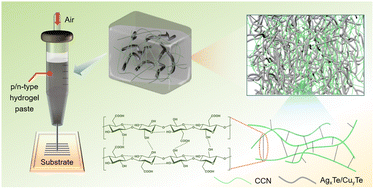
To form the hydrogel pastes, the cross-linking materials play a crucial role. To ensure the high conductivity of the printed TE legs, these hydrogel pastes need to be printed even at both low crosslink densities and low polymer concentrations.29 Therefore, CCN was chosen as the skeleton of the hydrogels because extremely high aspect ratio and rich functional groups can enhance hydrogel stability and printability even at low concentrations.30,31 CCN also possesses an ultrafine nanofibrous network structure, which may be useful to confine the NRs for constructing the printable hydrogel pastes. The printing illustration and hydrogel structure are depicted in Fig. 1. The as-prepared hydrogel pastes are physically crosslinked by intermolecular hydrogen bonding among the CCNs,31,32 which tend to exhibit water loss characteristics when subjected to the influence of an external environment such as high temperature. This property is necessary for the printed gel to form the solid TE legs after printing. In addition, the high-length CCNs are also able to entangle during stirring, exhibiting the advantage of the confinement of NR dispersion. By adjusting the ratio of CCN/H2O, the viscosity of the hydrogel pastes can be controlled, which reach the level of printing. In these hydrogel pastes, the 1D Te-based nanomaterials were employed as the TE components. The 3D network of CCNs formed by physical crosslinking and entanglement can effectively control the fluidity of the 1D Te-based nanomaterials, which avoids the diffusion of the printed hydrogel pastes to some degree after printing. Therefore, the printed legs enable stay on the print path after printing, maintaining accurate dimensions.
image file: d2nr05733f-f1.tif
Fig. 1 Schematic of the relationship between the physical crosslinking mechanism, the confinement of AgxTe/CuyTe NR dispersions, and the hydrogel pastes with high aspect ratio CCNs, and their applications as printing inks.

Furthermore, we compared this CCN-based hydrogel paste with other commercial hydrogels to highlight the advantages, where the mass ratio of several organics/H2O in the hydrogels was all controlled to 0.498 wt%. As shown in Fig. 2a, the hydrogels formed by physical crosslinking and entanglement will lose water in the external environment after being printed, which may cause different degrees of shrinkage or expansion on the substrates. To evaluate the retention after printing, the printed hydrogels are shown in Fig. 2b, including CCNs, sodium carboxymethyl cellulose (SCC), carboxymethyl chitosan (CC), and gelatin (G) hydrogels. The CCNs-based hydrogel paste shows the best shape-retaining ability after printing. Considering that polyimide is usually chosen as the f-TEG substrate, we tested the contact angles of the hydrogel pastes on the polyimide film (Fig. 2c). The CC and CCN hydrogels present larger contact angles compared with other hydrogels, but the height of the CCN hydrogel is larger than that of the CC hydrogel, therefore demonstrating the optimal capability of shape retention. To quantitatively assess the retention capability, the relative slump originating from the engineering field was calculated by dividing the height of the diffused hydrogels by the height of the conical container.33,34 The ∼12% relative slump of the CCNs hydrogel means that 85–90% height can be maintained compared with the initial state, which is 3 times higher than that of other hydrogels, demonstrating the excellent retention capacity. In addition, we also tested the water loss performance of the hydrogels under specific heating temperatures, as seen in Fig. 2e. The water, SCC hydrogel, and CCN hydrogel exhibit approximately fast water loss ratio at 313 K, where the CCN hydrogel dried completely after ∼15 min. This fast water loss facilitated the rapid formation of printed TE legs, which is beneficial to implement the precise control of the dimension size.


image file: d2nr05733f-f2.tif
Fig. 2 (a) Schematic diagram of gelation and water loss of the CCN hydrogel through inter-entanglement and physical crosslinking. (b) Photograph of the printed hydrogel pastes; the glass was used as the substrate. (c) Contact angles of different hydrogel pastes on the PI substrate. (d) Slump comparison: the percentage of the height of the hydrogel pastes to the container after the removal of the conical container. (e) Water loss rates as a function of time, where the concentrations of organics are 0.625 wt%. Ambient temperature and humidity are 313 K and 40%, respectively.

Except for the printability of hydrogel pastes, another focus is on the TE performance. Although numerous conductive polymers have been reported,35,36 their TE properties are still low compared to inorganic semiconductor materials.37 Among inorganic TE materials, 1D Te-based inorganic NRs exhibit excellent TE performance owing to the effect of “quantum well”,9,38–40 which were employed in hydrogel pastes to achieve outstanding TE performance. Another advantage is that the Te-based NRs can exhibit the p- and n-type conductivity respectively through chemical modification,9,41–43 which achieves high TE performance of the printed materials while obtaining p- and n-type TE legs. Firstly, Te NRs as a template for Te-based nanomaterials were synthesized using a solvothermal method, and then Ag and Cu were grown in situ on the Te NR surface in weakly reducing EG. The synthetic strategies of CuyTe and AgxTe NRs are shown in Fig. S1 and Experimental methods. The XRD patterns of Te NR, AgxTe NR, and CuyTe NR are shown in Fig. S2. The XRD peaks indicate that the hexagonal crystalline phase of the Te NRs is in good agreement with the standard Te phase (PDF#36-1452), which demonstrates the pure Te crystalline phase. The sharp diffraction peaks and narrow half-peak width prove the high crystallinity. However, the peaks of AgxTe and CuyTe NRs are slightly shifted compared to the standard Ag2Te (PDF#34-0142) and Cu2Te phases (PDF#10-0421), which may be attributed to the different doping degrees of the metal atoms. The SEM and TEM images were used for the further characterization of the NRs, as shown in Fig. S3. Compared with the morphology of Te NR, AgxTe and CuyTe NR exhibited different degrees of deformation, which may be caused by the uneven growth of metals on the surface of Te NR. The energy-dispersive spectroscopy (EDS) mappings of AgxTe and CuyTe NR show the distribution of spatial elements, demonstrating the growth of Ag and Te on the surface of Te NRs.

To determine the optimal nominal molar ratio for maximizing the TE performance of hydrogel pastes, we tested the TE properties of the AgxTe and CuyTe NR films with different nominal molar ratios. The n-type Ag4Te NRs and p-type Cu1.5Te exhibit the maximum power factor of ∼101.4 and 64.3 μW m−1 K−2 at RT (Fig. 3a and b), which was selected as the p- and n-type TE components in this work. Next, we evaluate the effect of the CCN concentration on the viscosity of thermoelectric pastes and affinity to different substrates. As shown in Fig. S4, the viscosity of hydrogel pastes increases with increasing CCN content, while it decreases with increasing shear ratio, which is an important characteristic to ensure that hydrogel pastes that can be printed. Another point of concern is that the addition of Te-based NRs further increases the viscosity of the pastes so as to improve the printability. The corresponding contact angels also demonstrate that the increase in the CCN concentration is beneficial for maintaining the slump and the addition of Te-based NRs also helps to improve the contact angles (Fig. S5–S8). In addition, we compared the affinity of pastes to different substrates based on the contact angles (Fig. S5–S8). The results reveal that the hydrogel pastes maintain a high slump on different substrates when the concentration of CCN in the pastes is ≥0.498 wt%, and the printed TE legs show a more uniform and dense morphology than that of pastes with lower CCN concentration (Fig. S9), which provides a practical basis for printing high-performance f-TEGs on different substrates.


image file: d2nr05733f-f3.tif
Fig. 3 Seebeck coefficient, electrical conductivity, and power factor of the (a) AgxTe and (b) CuyTe as a function of nominal molar ratio. Seebeck coefficient, electrical conductivity, and power factor of the (c) AgxTe and (d) CuyTe as a function of the CCN content. (e) Schematic of the printed f-TEG based on the p- and n-type hydrogel pastes. (f) Schematic illustration showing the pressing process of the f-TEG. The SEM images of (g) n-type Ag4Te and (h) p-type Cu1.5Te legs. The SEM images of (i) n-type Ag4Te and (j) p-type Cu1.5Te legs after pressing. (k) The electrical conductivity of the printed thermoelectric legs. (l) The Seebeck coefficient of the printed thermoelectric legs.

Further, the effects of CCN content on the Seebeck coefficient and electrical conductivity of the printed thermoelectric legs were evaluated, as shown in Fig. 3c and d. With the increase in the CCN content, the Seebeck coefficient of the printed n- and p-type legs did not decrease significantly but the electrical conductivity gradually declines, thus leading to a gradual decrease in the power factor. When the ratio of CCN/H2O in the p- and n-type pastes is 0.498 wt%, the printed thermoelectric legs in the gel state demonstrated excellent shape retention, which did not exhibit a significant slump. Combining the thermoelectric performance and printability, this ratio of 0.498 wt% CCN/H2O is employed in the subsequent printing of f-TEG.

The schematic structure of the printed f-TEG is shown in Fig. 3e, where the highly sophisticated bio-3D printer was employed to construct this f-TEG (Fig. S10). To increase the denseness of the legs, we further employed the pressing technique to process the printed films (Fig. 3f). After the p- and n-hydrogel pastes were successively printed on the flexible substrate and dried at 323 K, the silver paste printed with the same parameters was used as the connection of the p- and n-type legs in series electrically and in parallel thermally. Fig. 3g and h present the microstructures of printed p- and n-type legs, where the p- and n-type TE components are Cu1.5Te and Ag4Te NRs, respectively. Attributed to the residual porosity of the hydrogel pastes after drying, the TE legs exhibit loose microstructures, which cannot provide an efficient transmission path for the carriers. As shown in Fig. 3i and j, the pressed films exhibit denser structures than before pressing, which is beneficial to enhance the carrier transport to improve the TE performance. The next focus is on the feasibility of printing on different substrates such as PI, cellulose, nylon, and PVDF films. We printed the same p- and n-type hydrogel pastes on these films with different patterns, where the printed patterns need to be designed in advance using engineering software and then imported to the printer. As seen in Fig. S11, the hydrogel pastes can be precisely deposited on these substrates in triangular, rectangular, circular, curve, and other polygonal shapes, which shows the potential to fabricate various f-TEGs using different structures. Fig. S12 exhibits the printed f-TEGs with the bend, folded, and rolled state, demonstrating excellent flexibility and mechanical strength. Except for the flexibility, another advantage is that the different morphological f-TEGs can be achieved by combining the design of printed arrays with different structural substrates, as depicted in Fig. S12c–S12e. To evaluate the TE performance, the electrical conductivity and Seebeck coefficient of the p- and n-type legs were measured, as shown in Fig. 3k and l, respectively. The pressed n- and p-type TE legs exhibit excellent electrical conductivity of ∼145.1 and 734.6 S cm−1, respectively, which is 4 times higher than that of the unpressed legs (Fig. 3k). The electrical conductivity of our thermoelectric legs is higher than that of previous reports (Table S1). The amount of insulating organic in our work is 60% less than previous researches so as to achieve relatively high conductivity. It is worth noting that the electrical conductivity of the pressed TE legs only yielded a decrease of <3% compared to the pure NR films, demonstrating the capability of the hydrogel-based printing strategy to maintain the electrical properties of the TE legs because of the high 97.5 wt% ratio of inorganic NRs in the composite legs. Except for the electrical conductivity, the Seebeck coefficient of the pressed TE legs is only 5% lower than that of the pure NR films (−78.1 μV K−1, 28.1 μV K−1 respectively) (Fig. 3l), and this difference may also be caused by the testing accuracy of the instrument.

Further, we tested and calculated the output voltage, current, and the output power of the printed f-TEGs composed of different TE couples as a function of temperature differences (Fig. 4). As shown in Fig. 4a, the increasing output voltage is proportional to the TE couples when the temperature differences are 10, 30, and 50 K, manifesting that a higher voltage can be achieved further by increasing the TE couples and temperature gradient. Similarly, the experimental voltage increases as the temperature difference (Fig. 4b), which is fitted to a linear relationship through the red curve. The optimized open-circuit voltage is ∼500 mV at a temperature difference of 70 K when the TE couple is 70, which outperforms previously reported f-TEGs.4,6,7,26 In addition, we investigated the thermal reliability and stability in Fig. 4c and d. The constant open-circuit voltage is ∼11, ∼29, and ∼48 mV during the continuous temperature cycle when the temperature gradients are 10, 30, and 50 K, respectively, demonstrating a stable value across each TE couple for each working cycle (Fig. 4c). To evaluate the mechanical compliance, the resistance value of the f-TEG with 10 TE couples during cyclic bending is shown in Fig. 4d where the bending frequency is 16 s each time. The decline in the conductivity is less than 24% after 2000 s of bending cycles with a 1.5 mm radius of curvature. Fig. 4e shows the current and output power as a function of the output voltage at ΔT = 10, 30, and 50 K, respectively. The voltage-current curves vary linearly with the optimized output power of 157 nW when the temperature difference at the two ends is 30 K. When the ΔT is increased to ∼50 K, the maximum output power of 378 nW is observed. The maximum power density as a function of temperature gradients can be calculated using the following equation44

 
image file: d2nr05733f-t1.tif(1)
where Pmax represents the maximum output power, N, and A represent the number and crosssectional area of the TE legs, respectively. As shown in Fig. 4f, the maximum power densities of the f-TEG are 0.081, 0.282, 0.534, 0.859, and 1.278 W m−2 when the ΔT increases from 10 to 50 K, where the experimental data conform to the quadratic fitting relationship. These results indicate that the printed f-TEGs can generate a high output with the fully mechanized process, which is favorable for harvesting waste heat from various curved surfaces. To prove that the f-TEG can continuously power output with an optimized resistance load, hourly tests of up to 75 h were implemented (Fig. 4g and h). The stable load voltage, current, and output power all demonstrated that the f-TEG with an optimized resistance load can output power continuously and stably under long-term operating conditions. Further, the operating stability under a large temperature difference or a high humidity needs to be verified because of the presence of CCN. As the humidity increases, the output voltage and current in the circuit remain generally stable despite slight fluctuations (<6% and <3%, respectively) (Fig. S13a), and the output power only produces ∼10% reduction even if the humidity increases from 60% to 95% (Fig. S13b), which is mainly attributed to the low CCN content and the dense structure of the TE legs for preventing CCN from absorbing water from the surrounding area. In addition, the f-TEG showed no observable degradation in the output voltage and current during continuous testing for up to 110 h when the temperature difference and the humidity were 50 K and 95%, respectively (Fig. S13c). Based on these test results, we can infer that the f-TEG can remain stable during several months of operation.


image file: d2nr05733f-f4.tif
Fig. 4 (a) The generated voltage as a function of TE couples when the temperature gradient is 10, 30, and 50 K. (b) Open-circuit voltage as a function of temperature difference at N = 10, 40, and 70. (c) Open-circuit voltage at various ΔT, where the N is 10. (d) Resistance value of the printed f-TEG with 10 TE couples during 2000 s of bending cycles. Radius of curvature is 1.5 mm and the frequency is 7 s each time. (e) Current and output power of the f-TEG composed of 10 couples as a function of voltage at ΔT = 10, 30, and 50 K, respectively. (f) Power density of the f-TEG composed of 10 couples at various temperature gradients. (g) Load voltage and current in the closed circuit with optimized resistance, where the couple of f-TEG is 10 and the ΔT is 10 K. (h) Output power of the f-TEG with 10 couples of legs at ΔT = 10 K.

Conclusion

In this study, the p- and n-type hydrogel pastes were developed and used as printing inks for fabricating the high-performance f-TEG. The high viscosity of the printing pastes was achieved by physically crosslinking the CCNs and entangling the molecular chains with a high aspect ratio, therefore realizing the confinement on the fluidity of the CuyTe and AgxTe NR dispersions. Owing to the rational design of the hydrogel pastes, the printed f-TEGs can be stably deposited on a variety of substrates in multifarious configurations, proving their potential usability in integrating diversified f-TEGs. The f-TEG consisting of 70 TE couples can generate a voltage of ∼500 mV at a temperature difference of 70 K, and the specific power density is up to 1.278 W m−2 at ΔT = 50 K. This work demonstrates that the printed f-TEGs can effectively convert the waste heat into useful electricity, which will help advance the wearable f-TEGs and even flexible electronics.

Author contributions

C. Hou, Y. Li and H. Wang guided the project. B. Wu, J. Geng, C. Hou, and Y. Li conceived the idea and designed the experiment. B. Wu and J. Geng performed the experiments and measurements. Q. Zhang and Y. Lin revised the manuscript. All authors analyzed the experimental data, drew the figures, and prepared the manuscript. All authors discussed the results and commented on the manuscript.

Conflicts of interest

The authors declare no conflict of interest.

Acknowledgements

B. W. and J. X. contributed equally to this work. This work was supported by the National Natural Science Foundation of China (No. 51873033), DHU Distinguished Young Professor Program (LZB2019002), Shanghai Rising-Star Program (20QA1400300), the Fundamental Research Funds for the Central University and Graduate Student Innovation Fund of Donghua University (CUSF-DH-D-2020033), and Shanghai Student Innovation and Entrepreneurship Training Program (S202210255321).

References

  1. B. Wu, Y. Guo, C. Hou, Q. Zhang, Y. Li and H. Wang, Nano Energy, 2021, 89, 106487 CrossRef CAS.
  2. W. Ren, Y. Sun, D. Zhao, A. Aili, S. Zhang, C. Shi, J. Zhang, H. Geng, J. Zhang, L. Zhang, J. Xiao and R. Yang, Sci. Adv., 2021, 7, eabe0586 CrossRef CAS PubMed.
  3. Y. Guo, C. Dun, J. Xu, P. Li, W. Huang, J. Mu, C. Hou, C. A. Hewitt, Q. Zhang, Y. Li, D. L. Carroll and H. Wang, ACS Appl. Mater. Interfaces, 2018, 10, 33316–33321 CrossRef CAS PubMed.
  4. K. Wang, C. Hou, Q. Zhang, Y. Li and H. Wang, Nano Energy, 2022, 95, 107055 CrossRef CAS.
  5. J. Geng, B. Wu, Y. Guo, C. Hou, Y. Li, H. Wang and Q. Zhang, J. Appl. Phys., 2021, 54, 153002 Search PubMed.
  6. Q. Zhou, K. Zhu, J. Li, Q. Li, B. Deng, P. Zhang, Q. Wang, C. Guo, W. Wang and W. Liu, Adv. Sci., 2021, 8, 2004947 CrossRef CAS PubMed.
  7. B. Wu, Y. Guo, C. Hou, Q. Zhang, Y. Li and H. Wang, Adv. Funct. Mater., 2019, 29, 1900304 CrossRef.
  8. J. Li, Q. Shi, J. A. Röhr, H. Wu, B. Wu, Y. Guo, Q. Zhang, C. Hou, Y. Li and H. Wang, Adv. Funct. Mater., 2020, 30, 2002508 CrossRef CAS.
  9. C. Zhou, C. Dun, Q. Wang, K. Wang, Z. Shi, D. L. Carroll, G. Liu and G. Qiao, ACS Appl. Mater. Interfaces, 2015, 7, 21015–21020 CrossRef CAS PubMed.
  10. J. A. Perez-Taborda, O. Caballero-Calero, L. Vera-Londono, F. Briones and M. Martin-Gonzalez, Adv. Energy Mater., 2018, 8, 1702024 CrossRef.
  11. L. Song, J. Zhang and B. B. Iversen, J. Mater. Chem. A, 2019, 7, 17981–17986 RSC.
  12. L. Song, J. Zhang and B. B. Iversen, ACS Appl. Energy Mater., 2020, 3, 2055–2062 CrossRef CAS.
  13. X. Tang, Z. Li, W. Liu, Q. Zhang and C. Uher, Interdiscip. Mater., 2022, 1, 88–115 CrossRef.
  14. Y. Guo, J. Mu, C. Hou, H. Wang, Q. Zhang and Y. Li, Carbon, 2016, 107, 146–153 CrossRef CAS.
  15. P. Cataldi, M. Cassinelli, J. A. Heredia-Guerrero, S. Guzman-Puyol, S. Naderizadeh, A. Athanassiou and M. Caironi, Adv. Funct. Mater., 2020, 30, 1907301 CrossRef CAS.
  16. J. D. Ryan, D. A. Mengistie, R. Gabrielsson, A. Lund and C. Muller, ACS Appl. Mater. Interfaces, 2017, 9, 9045–9050 CrossRef CAS PubMed.
  17. L. Jin, T. Sun, W. Zhao, L. Wang and W. Jiang, J. Power Sources, 2021, 496, 229838 CrossRef CAS.
  18. Y. Yang, H. Hu, Z. Chen, Z. Wang, L. Jiang, G. Lu, X. Li, R. Chen, J. Jin, H. Kang, H. Chen, S. Lin, S. Xiao, H. Zhao, R. Xiong, J. Shi, Q. Zhou, S. Xu and Y. Chen, Nano Lett., 2020, 20, 4445–4453 CrossRef CAS PubMed.
  19. B. Lee, H. Cho, K. T. Park, J. S. Kim, M. Park, H. Kim, Y. Hong and S. Chung, Nat. Commun., 2020, 11, 5948 CrossRef CAS PubMed.
  20. K. Nan, S. D. Kang, K. Li, K. J. Yu, F. Zhu, J. Wang, A. C. Dunn, C. Zhou, Z. Xie, M. T. Agne, H. Wang, H. Luan, Y. Zhang, Y. Huang, G. J. Snyder and J. A. Rogers, Sci. Adv., 2018, 4, eaau5849 CrossRef CAS PubMed.
  21. T. Juntunen, H. Jussila, M. Ruoho, S. Liu, G. Hu, T. Albrow-Owen, L. W. T. Ng, R. C. T. Howe, T. Hasan, Z. Sun and I. Tittonen, Adv. Funct. Mater., 2018, 28, 1800480 CrossRef.
  22. M. S. Hossain, T. Li, Y. Yu, J. Yong, J. H. Bahk and E. Skafidas, RSC Adv., 2020, 10, 8421–8434 RSC.
  23. B. Chen, M. Kruse, B. Xu, R. Tutika, W. Zheng, M. D. Bartlett, Y. Wu and J. C. Claussen, Nanoscale, 2019, 11, 5222–5230 RSC.
  24. D. Madan, Z. Wang, A. Chen, R.-c. Juang, J. Keist, P. K. Wright and J. W. Evans, ACS Appl. Mater. Interfaces, 2012, 4, 6117–6124 CrossRef CAS PubMed.
  25. M. Saeidi-Javash, W. Kuang, C. Dun and Y. Zhang, Adv. Funct. Mater., 2019, 29, 1901930 CrossRef.
  26. C. Dun, W. Kuang, N. Kempf, M. Saeidi-Javash, D. J. Singh and Y. Zhang, Adv. Sci., 2019, 6, 1901788 CrossRef CAS PubMed.
  27. M. Zeng, D. Zavanelli, J. Chen, M. Saeidi-Javash, Y. Du, S. LeBlanc, G. J. Snyder and Y. Zhang, Chem. Soc. Rev., 2022, 51, 485–512 RSC.
  28. A. G. Rösch, A. Gall, S. Aslan, M. Hecht, L. Franke, M. M. Mallick, L. Penth, D. Bahro, D. Friderich and U. Lemmer, npj Flexible Electron., 2021, 5, 1–8 CrossRef.
  29. A. Shavandi, S. Hosseini, O. V. Okoro, L. Nie, B. E. Farahnaz and F. Melchels, Adv. Healthcare Mater., 2020, 9, 2001472 CrossRef CAS PubMed.
  30. L. Mendoza, T. Gunawardhana, W. Batchelor and G. Garnier, J. Colloid Interface Sci., 2018, 525, 119–125 CrossRef CAS PubMed.
  31. Y. Ye, Y. Zhang, Y. Chen, X. Han and F. Jiang, Adv. Funct. Mater., 2020, 30, 2003430 CrossRef CAS.
  32. K. Liu, J. Lv, G. Fan, B. Wang, Z. Mao, X. Sui and X. Feng, Adv. Funct. Mater., 2022, 32, 2107105 CrossRef CAS.
  33. Y. W. D. Tay, Y. Qian and M. J. Tan, Composites, Part B, 2019, 174, 106968 CrossRef CAS.
  34. N. Roussel, Cem. Concr. Res., 2018, 112, 76–85 CrossRef CAS.
  35. Y. M. Xie, Q. Yao, Q. Xue, Z. Zeng, T. Niu, Y. Zhou, M. P. Zhuo, S. W. Tsang, H. L. Yip and Y. Cao, Interdiscip. Mater., 2022, 1, 281–293 CrossRef.
  36. W. Shi, Z. Shuai and D. Wang, Adv. Funct. Mater., 2017, 27, 1702847 CrossRef.
  37. X. L. Shi, J. Zou and Z. G. Chen, Chem. Rev., 2020, 120, 7399–7515 CrossRef CAS PubMed.
  38. L. D. Hicks and M. S. Dresselhaus, Phys. Rev. B: Condens. Matter Mater. Phys., 1993, 47, 12727 CrossRef CAS PubMed.
  39. C. Zhou, C. Dun, B. Ge, K. Wang, Z. Shi, G. Liu, D. L. Carroll and G. Qiao, Nanoscale, 2018, 10, 14830–14834 RSC.
  40. X. Haifeng, H. Chengyi, Z. Qinghong, L. Yaogang and W. Hongzhi, J. Inorg. Mater., 2020, 35, 1034–1040 CrossRef.
  41. X. Zeng, C. Yan, L. Ren, T. Zhang, F. Zhou, X. Liang, N. Wang, R. Sun, J.-B. Xu and C.-P. Wong, Adv. Electron. Mater., 2019, 5, 1800612 CrossRef.
  42. J. Gao, L. Miao, C. Liu, X. Wang, Y. Peng, X. Wei, J. Zhou, Y. Chen, R. Hashimoto, T. Asaka and K. Koumoto, J. Mater. Chem. A, 2017, 5, 24740–24748 RSC.
  43. D. Park, H. Ju, T. Oh and J. Kim, Sci. Rep., 2018, 8, 1–10 Search PubMed.
  44. Q. Meng, Y. Qiu, K. Cai, Y. Ding, M. Wang, H. Pu, Q. Yao, L. Chen and J. He, ACS Appl. Mater. Interfaces, 2019, 11, 33254–33262 CrossRef CAS PubMed.

Footnote

Electronic supplementary information (ESI) available. See DOI: https://doi.org/10.1039/d2nr05733f

This journal is © The Royal Society of Chemistry 2022