
 Open Access Article
 This Open Access Article is licensed under a Creative Commons Attribution-Non Commercial 3.0 Unported Licence
Yolk–shell-type CaO-based sorbents for CO2 capture: assessing the role of nanostructuring for the stabilization of the cyclic CO2 uptake†
Maximilian
Krödel
 ,
Alexander
Oing
,
Jan
Negele
,
Annelies
Landuyt
,
Agnieszka
Kierzkowska
,
Alexander H.
Bork
,
Felix
Donat
and
Christoph R.
Müller
*
,
Alexander
Oing
,
Jan
Negele
,
Annelies
Landuyt
,
Agnieszka
Kierzkowska
,
Alexander H.
Bork
,
Felix
Donat
and
Christoph R.
Müller
*
Department of Mechanical and Process Engineering, Laboratory of Energy Science and Engineering, ETH Zurich, Leonhardstrasse 21, 8092, Zurich, Switzerland. E-mail: muelchri@ethz.ch
First published on 10th October 2022
Abstract
Improving the cyclic CO2 uptake stability of CaO-based solid sorbents can provide a means to lower CO2 capture costs. Here, we develop nanostructured yolk(CaO)–shell(ZrO2) sorbents with a high cyclic CO2 uptake stability which outperform benchmark CaO nanoparticles after 20 cycles (0.17 gCO2 gSorbent−1) by more than 250% (0.61 gCO2 gSorbent−1), even under harsh calcination conditions (i.e. 80 vol% CO2 at 900 °C). By comparing the yolk–shell sorbents to core–shell sorbents, i.e. structures with an intimate contact between the stabilizing phase and CaO, we are able to identify the main mechanisms behind the stabilization of the CO2 uptake. While a yolk–shell architecture stabilizes the morphology of single CaO nanoparticles over repeated cycling and minimizes the contact between the yolk and shell materials, core–shell architectures lead to the formation of a thick CaZrO3-shell around CaO particles, which limits CO2 transport to unreacted CaO. Hence, yolk–shell architectures effectively delay CaZrO3 formation which in turn increases the theoretically possible CO2 uptake since CaZrO3 is CO2-capture-inert. In addition, we observe that yolk–shell architectures also improved the carbonation kinetics in both the kinetic- and diffusion-controlled regimes leading to a significantly higher cyclic CO2 uptake for yolk–shell-type sorbents.
1. Introduction
Climate change due to anthropogenic greenhouse gas emissions into the atmosphere is one of the most pressing challenges of our modern society.1,2 Net greenhouse gas emissions have to be reduced significantly in order to reach the IPCC's recommendation of limiting global warming to less than 2 °C compared to pre-industrial levels.3 Carbon dioxide capture and storage (CCS) technologies are a potential near- to mid-term solution to mitigate the emissions of carbon dioxide (CO2), arguably the most prominent greenhouse gas.3 CaO-based sorbents are a viable class of materials to capture CO2 emitted by large point sources.4–6 The associated cyclic CO2 capture process is referred to as calcium looping (CaL) and is based on the reversible reaction of CaO and CO2:
CaO-based sorbents are non-toxic and cost-effective (estimated capture cost of <30 USD per tCO2) compared to the current benchmark technology for CO2 capture, i.e. amine scrubbing (estimated capture costs of 40 to 55 USD per tCO2).7–9 However, CaO-based sorbents are prone to rapid deactivation, i.e. a reduction of their cyclic CO2 uptake capacity from a theoretical maximum of 0.78 gCO2 gCaO−1 to typically <0.2 gCO2 gCaO−1, largely due to sintering at the high operating temperatures (around 650–900 °C).10–12 Various approaches to mitigate sintering-induced deactivation have been reported, including (I) the addition of high Tammann-temperature stabilizers such as MgO, Al2O3 or ZrO2,13–18 (II) the (re-)structuring of the morphology of sorbents,14,19e.g. using steam treatment,20 or (III) the manufacture of materials with a high surface area and pore volume.19
The stabilization of CaO-based sorbents using metal oxides such as MgO, Al2O3 and ZrO2 has been widely applied and currently there are very few new sorbent formulations that do not contain either such structural stabilizers, promoters (e.g. alkali metal salts like Na2CO3) or other performance-enhancing precursors (e.g. Ca-precursors containing alcohol groups).5,14,16,17,21–25 The best reported materials exhibit cyclic CO2 uptakes of up to 0.65 gCO2 gSorbent−1 after 10 carbonation–calcination cycles, which is six times higher compared to the benchmark limestone.26 Here, the high Tammann-temperature stabilizer MgO is believed to act as a physical barrier (spacer) between the CaO grains, reducing in turn their sintering (or the sintering of the CaCO3 formed).5,21,27,28 Hence, the size and distribution of these structural stabilizers within the CaO matrix must play an important role in mitigating sintering. It is important to note that the homogeneity of the distribution of the stabilizer might dynamically change with cycling (and indeed possibly even within one carbonation–calcination cycle). For example, Kim et al.15 observed that the stabilizer Ca3Al2O6 migrates to the surface of CaO particles during cycling, reducing in turn the stabilizer's effectiveness in reducing sintering. Therefore, one of the proposed design criteria for effective CaO-based sorbents is a low mobility of the stabilizing phase to avoid the loss of its stabilizing functionality. In addition, many investigated stabilizers form mixed phases with CaO at CaL conditions (650–900 °C) that are inactive for CO2 uptake, e.g. Ca3Al2O3 or CaZrO3.11,19,29,30 The formation of mixed phases that do not absorb CO2 results in a reduced amount of reactive CaO, reducing the theoretically achievable CO2 uptake of the sorbent. Hence, the synthesis of structures in which the interaction between CaO and the stabilizer is minimized to limit the formation of CO2-capture-inactive mixed oxides is desirable.
Like many gas–solid reactions, the carbonation reaction of CaO proceeds in two principal reaction regimes: a kinetically-controlled, rapid CO2 uptake regime that is followed by a much slower, diffusion-controlled CO2 uptake regime.31–33 While the CO2 uptake during the kinetically-controlled regime is largely controlled by the available pore volume and surface area, the apparent rate of reaction in the diffusion-controlled reaction regime is affected by morphological and structural parameters, e.g. the effective diffusivity of CO2 in the material.21 In previous works, the transition between the two reaction regimes has been associated with the formation of a product layer of CaCO3 on top of CaO, which causes the blockage of pores such that a certain fraction of the pore volume and surface area of the sorbent becomes inaccessible for CO2 molecules.34–36 For a two-dimensional surface of a non-porous material it has been hypothesized that once the product layer reaches a critical thickness (estimated to be around 30–50 nm by various works34,37,38), the reaction transitions from kinetic control to diffusion control.39 To maximize the CO2 uptake in the kinetically-controlled regime, the nanostructuring of CaO (i.e. particle size < 60–100 nm) is highly favorable. Previous works concerned with CaO (or CaCO3) nanoparticles of size < 100 nm investigated uncoated nanoparticles or nanoparticles with coatings that have an intimate contact with the CaO nanoparticle core (core–shell structures), resulting in the formation of CO2-capture-inactive mixed phases and hence comparatively low CO2 uptake.40,41 For example, core–shell structures with CaCO3 cores and shells of ZrO2 or SiO2 have been reported to yield materials with a significantly stabilized cyclic CO2 uptake compared to bare CaCO3.29,42,43 However, these materials deactivated over prolonged cyclic operation via the formation of mixed oxides with calcium that both reduce the amount of CaO available for reaction and also affect negatively the carbonation kinetics. Instead, the structure of an optimized model CaO-based sorbent should exhibit the following attributes: (I) the structure should be composed of CaO nanoparticles of size < 100 nm to reduce the effect of product layer diffusion limitation.5,34,37 (II) It should utilize a stabilizer to avoid physical contact (and hence sintering) between the individual CaO nanoparticles. Applying a stabilizer shell around the CaO nanoparticles would yield this physical separation, but the direct contact between the stabilizer and CaO might lead to the formation of CO2-capture-inactive mixed phases. To prevent such direct contact, a sacrificial layer can be placed between the CaO nanoparticle and the stabilizer coating, creating upon its removal a space between the CaO nanoparticle and the stabilizing coating. (III) The stabilizer shell needs to be porous to allow for a fast transport of CO2 to the surface of CaO. Overall, these requirements would demand a yolk–shell-type structure. Hence in this work, we report on the synthesis of such model, yolk–shell-structured sorbents to probe whether the aforementioned requirements concerning sorbent design are indeed correct and to understand better the deactivation and stabilization mechanisms of nanostructured sorbents. We note that such sorbents are very likely not to be directly usable in an industrial CO2 sorption process in which mechanical stability of sorbent particles may be one of many additional constraints. However, the insights gained from this study will help to understand better the functioning of stabilizers, aiding the design of practically applicable, yet still superior sorbent systems.
To this end, we use CaCO3 nanoparticles with an average particle size < 100 nm that are stabilized by a porous shell of ZrO2 in a yolk(CaO)–shell(ZrO2) architecture. The presence of a yolk–shell-type structure is shown to ensure a high sintering resistance and high rates of transport of CO2 to CaO, while the formation of the CO2-capture-inactive CaZrO3 phase is avoided. The design approach is depicted in Fig. 1.
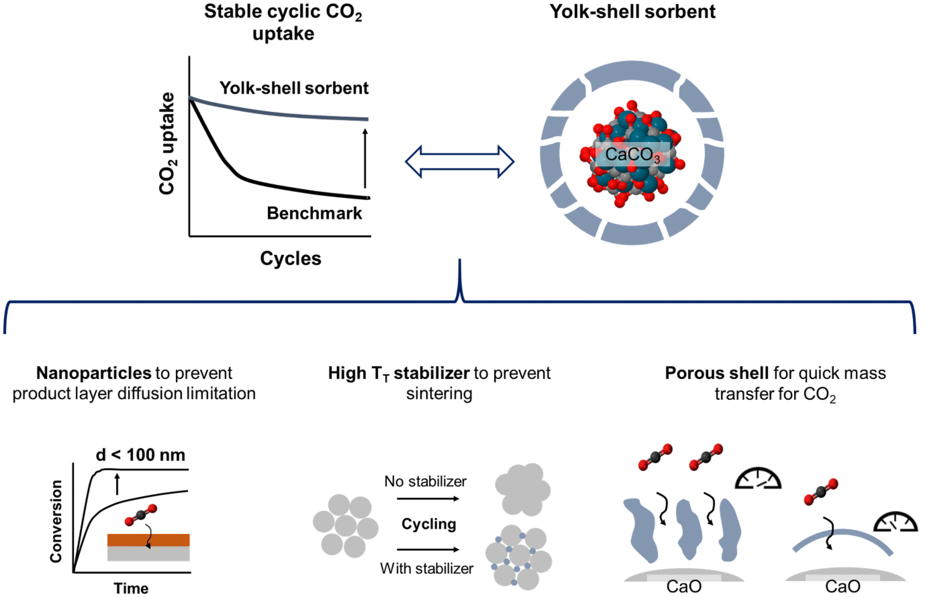 | ||
| Fig. 1 Design approach for yolk–shell-type CaO-based sorbents. Using a nanoparticle core is expected to prevent diffusive limitations due to product layer formation, whereas a porous shell of a high TT stabilizer shall mitigate sintering of the nanoparticles while at the same time allowing for a rapid transfer of CO2 to unreacted CaO. | ||
2. Experimental
2.1 Materials
2.2 Characterization
A FEI Magellan 400 FEG high resolution scanning electron microscope (SEM) was used for the textural and morphological analysis of the synthesized sorbents. The instrument was operated at an acceleration voltage of 10 kV and a beam current of 25 pA. To minimize charging effects during imaging, the samples were sputtered with a 4 nm thick film of Pt/Pd (80![[thin space (1/6-em)]](https://www.rsc.org/images/entities/char_2009.gif) :20) prior to SEM analysis.
:20) prior to SEM analysis.
 | (1) |
3. Results and discussion
3.1 Synthesis of the yolk–shell sorbents
To yield CaO–ZrO2-based yolk–shell-structured sorbents, a two-step synthesis approach was performed (Fig. 2a). First, commercial CaCO3 nanoparticles (Ca-NP, davg,CaCO3 = 67 nm, Fig. 2b) were coated with a carbonaceous shell (Ca@C, Fig. 2c).44 The thickness of the coating was about 40 nm, an optimized value to ensure a homogeneous carbonaceous layer, while avoiding the formation of separate carbonaceous spheres (Fig. S1†). The homogeneity of the carbonaceous coating was confirmed by EDX-TEM (Fig. 2c).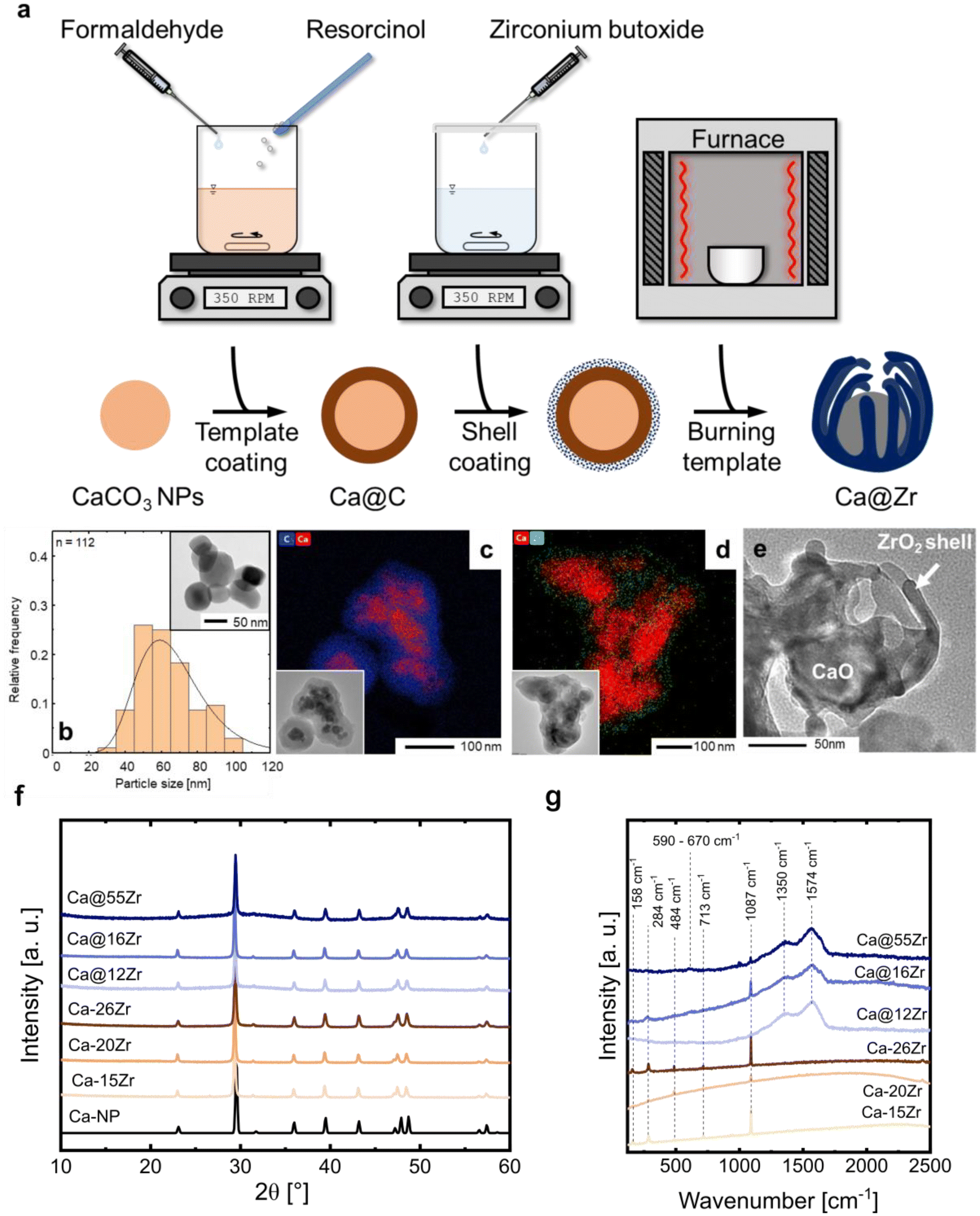 | ||
| Fig. 2 (a) Illustration of the two-step synthesis approach to yield yolk–shell-type structures containing a CaO yolk and a ZrO2 shell. (b) Particle size distribution of commercial CaCO3 nanoparticles determined by TEM, (c) TEM micrograph and EDX elemental map of CaCO3 nanoparticles coated with a homogeneous carbonaceous shell with an average thickness of 40 nm, (d) TEM micrograph and EDX elemental map of a sorbent containing both the carbonaceous template coating and the ZrO2 coating, (e) TEM micrograph of the calcined yolk–shell sorbent after template removal in synthetic air at 900 °C, (f) XRD patterns of Ca-NP and as-synthesized (prior to calcination) zirconia-stabilized sorbents, and (g) Raman spectra of as-synthesized sorbents. | ||
In the second step of the synthesis, the Ca@C particles were coated with a layer of Zr(OH)4 utilizing a wet-chemistry-based approach (see Materials section for details).45 A homogeneous coating with Zr(OH)4 (see below) was confirmed via EDX-TEM, see Fig. 2d. The resulting yolk–shell structure after calcination (synthetic air, 900 °C) is shown in Fig. 2e and will be discussed in more detail further below. Throughout this work, the nomenclature for yolk–shell sorbents will be Ca@xZr, where x is the experimentally determined amount of ZrO2 (in wt%) in the sorbent. As a reference material, CaCO3 NPs (Ca-NP) were also directly coated with zirconia using the same coating procedure but without addition of the carbonaceous shell, yielding core–shell sorbents. Throughout the manuscript, the core–shell sorbents will be referred to as Ca–xZr.
The structure of the as-synthesized (i.e. before the first calcination) sorbents was assessed by XRD and Raman spectroscopy. The XRD patterns of the reference material and the zirconia-stabilized yolk–shell and core–shell-type sorbents are shown in Fig. 2f. The diffractogram of Ca-NP (as received) showed only the characteristic diffraction peaks of CaCO3 (calcite polymorph). Also all of the yolk–shell and core–shell sorbents showed the diffraction peaks due to CaCO3. An amorphous halo with a maximum around approximately 2θ = 30°, relating to amorphous Zr(OH)4, was observed in the sorbents prior to their calcination.46 The ZrO2 content in the sorbents was estimated using Rietveld analysis of XRD data acquired of sorbents that have undergone 20 cycles and are listed in Table 1 (see Fig. S2 and Table S1† for details on the Rietveld refinement). The Raman spectra of the as-synthesized sorbents are shown in Fig. 2g. All yolk–shell sorbents (prior to calcination) showed features due to the D-band (1350 cm−1) and G-band (1574 cm−1) of carbon confirming the presence of a carbonaceous coating. These sorbents also show a weak band related to amorphous Zr(OH)4 between 590 and 670 cm−1, confirming the Zr phase observed in XRD.47 Additional features related to CaCO3 (158 cm−1, 284 cm−1, 713 cm−1, 1087 cm−1) were observed as well.
| Type | Sorbent | ZrO2 content [wt%] |
|---|---|---|
| Core–shell | Ca–15Zr | 15 |
| Core–shell | Ca–26Zr | 26 |
| Yolk–shell | Ca@16Zr | 16 |
| Yolk–shell | Ca@12Zr | 12 |
| Yolk–shell | Ca@55Zr | 55 |
3.2 Characterization of as-prepared sorbents after template removal
The as-synthesized sorbents were calcined in synthetic air (80 vol% N2, 20 vol% O2, 10 min at 900 °C, heating ramp of 25 °C min−1) to remove the carbonaceous template as well as to decompose CaCO3 into CaO, yielding as-prepared yolk–shell sorbents. The normalized weight (solid line) of Ca@C and the temperature ramp recorded during a TGA measurement (synthetic air, 175 ml min−1, heating ramp of 25 °C min−1) are shown in Fig. 3a. The initial mass loss (I) (T < 150 °C) is related to the release of residual solvent (water and ethanol) from the synthesis. The subsequent weight losses (II) and (III) are related to the removal of the carbonaceous template layer, resulting in a total weight loss of 35 wt% at 550 °C.48,49 At temperatures >600 °C, an additional weight loss (approximately 30% of the initial weight or 78% of the weight after full decomposition) is observed. This weight loss is due to the decomposition of CaCO3 to CaO through the release of CO2 (CaO has a theoretical CO2 uptake capacity of 0.78 gCO2 gSorbent−1).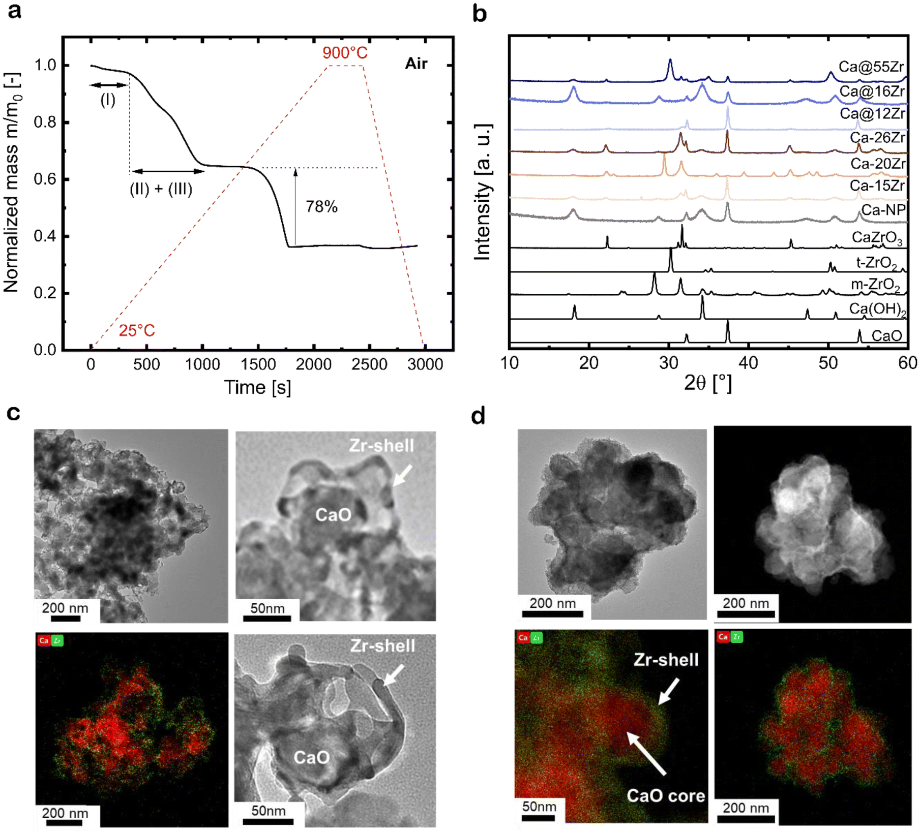 | ||
| Fig. 3 (a) Weight loss of CaCO3 nanoparticles containing a carbonaceous template coating during calcination in air (heating ramp of 25 °C min−1 up to 900 °C), (b) XRD patterns of calcined zirconia-stabilized sorbents after template removal; TEM micrographs and EDX-TEM elemental maps for Ca and Zr for (c) a zirconia-stabilized, yolk–shell structured sorbent (Ca@12Zr) and (d) a zirconia-stabilized, core–shell-structured sorbent (Ca–26Zr). | ||
To assure that the carbonaceous template was removed completely during calcination in synthetic air, we studied the decomposition and removal of the template by in situ Raman spectroscopy. Fig. S3† shows the Raman spectra of Ca@C during heat treatment in synthetic air (up to 550 °C). We observe the disappearance of hydroxyl groups ν(OH), at approximately 2800 cm−1, in the temperature range 50 to 100 °C, corresponding to mass release (I) as observed in the TGA measurement. The modes relating to the G-band and D-band of carbon decrease in intensity between 100 and 500 °C. At 550 °C, no features related to the D- and G-band were observed, confirming the complete removal of the carbonaceous template at 550 °C. The characteristic mode for CO32− (∼1087 cm−1) in CaCO3 is present at all temperatures (i.e. up to 550 °C). EDX-TEM analysis of the particles before and after calcination confirms the carbon removal; the respective images are shown in Fig. S3b and c.†
The structure of the as-prepared (i.e. calcined), zirconia-stabilized sorbents was assessed by XRD (Fig. 3b). The calcined core–shell particles show the characteristic diffraction peaks of both CaO (Fm![[3 with combining macron]](https://www.rsc.org/images/entities/char_0033_0304.gif) m space group, cubic) and CaZrO3 (Pcmn space group, orthorhombic). Unexpectedly, the intensity of the peaks related to CaZrO3 increased from Ca–15Zr to Ca–26Zr, indicating the formation of larger amounts of the mixed phase with increasing ZrO2 contents. Using Rietveld analysis (see Fig. S2 and Table S1†), we estimated the fraction of the CaZrO3 mixed phase in the core–shell sorbents Ca–15Zr and Ca–26Zr as 15 and 37 wt%, respectively. The XRD patterns of the yolk–shell sorbents Ca@16Zr and Ca@12Zr showed peaks due to CaO and very low intensity peaks possibly due to CaZrO3, which we were not able to quantify using Rietveld refinement (due to their small intensity). This suggests, considering the detection limit of the XRD setup, that in such sorbents the weight fraction of CaZrO3 is <1 wt%. In addition, no peaks due to ZrO2 were observed. Hence, in the yolk–shell sorbents Ca@12Zr and Ca@16Zr Zr is very likely present in an amorphous phase. However, for Ca@55Zr, tetragonal zirconia (t-ZrO2) was observed in addition to both CaO and CaZrO3. Rietveld refinement showed that this sorbent contained about 11 wt% CaZrO3 and 52 wt% t-ZrO2. In conclusion, compared to the core–shell particles, CaZrO3 formation was reduced in the yolk–shell-type sorbents (at similar ZrO2 contents), in particular when comparing Ca@16Zr and Ca–15Zr.
m space group, cubic) and CaZrO3 (Pcmn space group, orthorhombic). Unexpectedly, the intensity of the peaks related to CaZrO3 increased from Ca–15Zr to Ca–26Zr, indicating the formation of larger amounts of the mixed phase with increasing ZrO2 contents. Using Rietveld analysis (see Fig. S2 and Table S1†), we estimated the fraction of the CaZrO3 mixed phase in the core–shell sorbents Ca–15Zr and Ca–26Zr as 15 and 37 wt%, respectively. The XRD patterns of the yolk–shell sorbents Ca@16Zr and Ca@12Zr showed peaks due to CaO and very low intensity peaks possibly due to CaZrO3, which we were not able to quantify using Rietveld refinement (due to their small intensity). This suggests, considering the detection limit of the XRD setup, that in such sorbents the weight fraction of CaZrO3 is <1 wt%. In addition, no peaks due to ZrO2 were observed. Hence, in the yolk–shell sorbents Ca@12Zr and Ca@16Zr Zr is very likely present in an amorphous phase. However, for Ca@55Zr, tetragonal zirconia (t-ZrO2) was observed in addition to both CaO and CaZrO3. Rietveld refinement showed that this sorbent contained about 11 wt% CaZrO3 and 52 wt% t-ZrO2. In conclusion, compared to the core–shell particles, CaZrO3 formation was reduced in the yolk–shell-type sorbents (at similar ZrO2 contents), in particular when comparing Ca@16Zr and Ca–15Zr.
The morphologies of the calcined yolk–shell sorbents and core–shell sorbents were imaged using (EDX-)TEM, see Fig. 3c and d. The yolk–shell-structured sorbents Ca@12Zr (Fig. 3c) and Ca@16Zr (Fig. S4a†) exhibit individual CaO nanoparticles encapsulated by a Zr-containing shell with an occasionally dendritic appearance. The void space between the yolk and the shell, characteristic for the yolk–shell architecture, is clearly visible for Ca@12Zr. Ca@55Zr (Fig. S4b†) showed both larger agglomerates coated with a Zr-containing shell as well as some yolk–shell structures similar to the ones observed for Ca@16Zr and Ca@12Zr. For the larger agglomerates, the distribution of Ca and Zr, based on EDX-TEM, overlapped in intensity, indicating the formation of large CaZrO3 particles or CaZrO3-coated CaO particles, in line with our XRD observations (Fig. 3b). For high Zr contents (Ca@55Zr), TEM also shows the presence of ZrO2 particles, which are, taking into account the XRD results, related to t-ZrO2. The core–shell sorbent Ca–26Zr (Fig. 3d) exhibited a Zr-containing coating covering the whole surface of the CaO particles. Based on our XRD analysis, this coating is composed of a thick layer of CaZrO3. On the other hand, the calcined core–shell sorbent Ca–15Zr (Fig. S4c†) showed an inhomogeneous Zr-containing coating on the CaO particles, indicating that the added amount of ZrO2 was insufficient to completely coat the CaO nanoparticles with a Zr-containing phase. Based on our XRD analysis, we also expect the Zr-containing coating of Ca–15Zr to be CaZrO3.
3.3 Cyclic CO2 uptake of the nanostructured zirconia-stabilized sorbents
The cyclic CO2 uptake of the zirconia-stabilized yolk–shell sorbents and the references Ca-NP as well as the core–shell particles were assessed over 20 carbonation–calcination cycles (Fig. 4a). Sorbents with ZrO2 contents <10 wt% were not investigated in more detail because they did not form well-defined yolk–shell structures and hence exhibited a lower CO2 uptake than Ca-NP.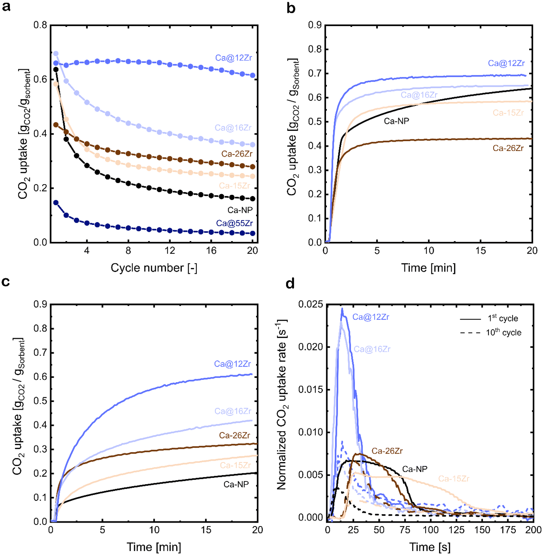 | ||
| Fig. 4 (a) Cyclic CO2 uptake over 20 carbonation–calcination cycles of zirconia-stabilized, yolk–shell-structured sorbents as well as core–shell-type sorbents and the CaCO3 NP reference; carbonation at 650 °C in 15 vol% CO2 and calcination at 900 °C in 80 vol% CO2, (b) CO2 uptake as a function of time in the 1st cycle and (c) 10th cycle of zirconia-stabilized sorbents and the CaCO3 NP reference, and (d) normalized CO2 uptake rate during the first 200 s of the 1st (—) and 10th (– – –) carbonation for zirconia-stabilized sorbents and the CaCO3 NP reference. | ||
The reference sorbent Ca-NP (without Zr) has a high CO2 uptake of 0.63 gCO2 gSorbent−1 in the first cycle. However, the CO2 uptake decreases rapidly with cycle number, reaching 0.21 gCO2 gSorbent−1 (decrease of 66% compared to the 1st cycle) and 0.17 gCO2 gSorbent−1 (decrease of 73% compared to the 1st cycle) after 10 and 20 cycles, respectively. The CO2 uptake of the yolk–shell-structured sorbents varied substantially with the content of Zr. Compared to Ca-NP (0.17 gCO2 gSorbent−1), Ca@16Zr and Ca@12Zr show significantly higher CO2 uptakes after 20 cycles, reaching, respectively, 0.38 gCO2 gSorbent−1 (maximum theoretical CO2 uptake of 0.65 gCO2 gSorbent−1) and 0.61 gCO2 gSorbent−1 (maximum theoretical CO2 uptake of 0.69 gCO2 gSorbent−1). In particular, the CO2 uptake performance of Ca@12Zr is promising, as it showed a relatively stable CO2 uptake over 20 cycles with only a small decrease from 0.66 gCO2 gSorbent−1 in the 1st cycle to 0.61 gCO2 gSorbent−1 (decrease of 8%) in the 20th cycle. For the sorbent with the highest zirconia content investigated (Ca@55Zr), very low CO2 uptakes of, respectively, 0.17 gCO2 gSorbent−1 and 0.04 gCO2 gSorbent−1 in the 1st and 20th cycle were observed. The low CO2 uptake of Ca-NP@55Zr was due to the large fraction of CO2-capture-inactive t-ZrO2 and CaZrO3 in this material as evidenced by XRD measurements (Fig. 3b). Turning to the core–shell structured sorbents, the most promising core–shell sorbent Ca–26Zr showed a significantly lower CO2 uptake in the 20th cycle (0.29 gCO2 gSorbent−1) compared to Ca@12Zr (0.61 gCO2 gSorbent−1). Further, the core–shell sorbent Ca–15Zr had a CO2 uptake of 0.27 gCO2 gSorbent−1 after 20 cycles, which is significantly lower than the CO2 uptake of its yolk–shell analogue with a similar ZrO2 content, i.e. Ca@16Zr (0.38 gCO2 gSorbent−1). Hence, a yolk–shell architecture yielded significantly better performing sorbents compared to the core–shell architecture (and the Ca-NP reference). This observation will be rationalized in the following sections.
3.4 The effect of nanostructuring on the carbonation kinetics
The carbonation kinetics in the 1st and 10th cycle of the most promising yolk–shell sorbents (Ca@16Zr and Ca@12Zr) and the core–shell analogues (Ca–15Zr and Ca–26Zr), as well as the reference Ca-NP are plotted in Fig. 4b and c. Independent of the material and the cycle number, the carbonation reaction can be divided into two reaction regimes, i.e. a fast, kinetically-controlled regime followed by a slower, diffusion-controlled regime. The effect of the yolk–shell and core–shell architectures on these regimes will be discussed below.First, we analyzed the effect of the yolk–shell and core–shell architectures on the kinetically-controlled regime. Based on the normalized CO2 uptake rate reaching a plateau, see Fig. 4d, we defined the end of the kinetically-controlled regime at t = 150 s for all sorbents. Within the kinetically-controlled regime in the 1st cycle, the yolk–shell sorbents reached significantly higher CO2 uptakes of 0.56 gCO2 gSorbent−1 (Ca@12Zr) and 0.51 gCO2 gSorbent−1 (Ca@16Zr) compared to the core–shell sorbents (0.3 gCO2 gSorbent−1 for Ca–15Zr and 0.28 gCO2 gSorbent−1 for Ca–26Zr) and Ca-NP (0.35 gCO2 gSorbent−1). Also, the maximum normalized CO2 uptake rate (Fig. 4d) achieved for the yolk–shell sorbents was significantly higher than for Ca–15Zr, Ca–26Zr and Ca-NP. In the 10th cycle, the CO2 uptake at the end of the kinetically-controlled regime was comparable for Ca@12Zr and Ca–26Zr, whereas Ca@16Zr, Ca–15Zr and Ca-NP showed a lower CO2 uptake. The maximum achieved CO2 uptake rate was also slightly higher for the yolk–shell sorbents than for the core–shell sorbents and the Ca-NP reference. In the kinetically-controlled regime in which the CO2 mass transfer resistance to reach the reaction surface is negligible, the reaction proceeds as a surface reaction. Hence, the CO2 uptake rate (dmCO2/dt) is proportional to the reaction surface area S0 and the reaction rate ks:
 | (2) |
As the reaction itself (i.e. the carbonation of CaO) has an intrinsic reaction rate ks,33,50,51 a higher maximum CO2 uptake rate implies a higher reaction surface area of CaO. Hence, we can conclude that a yolk–shell architecture improved the accessibility of CaO for reaction with CO2, i.e. provided sorbents with a higher reaction surface area compared to the core–shell sorbents and the Ca-NP reference. N2 physisorption measurements to further confirm this conclusion could not be conducted due to the small amount (<20 mg) of sorbent retained from a single synthesis.
The analysis of the kinetics in the diffusion-controlled regime, i.e. t > 150 s, will be discussed next. All sorbents exhibited a comparable CO2 uptake in the diffusion-controlled regime in the 1st cycle, see Fig. 4b. In the 10th cycle (Fig. 4c), the yolk–shell sorbents achieved a large part of their total CO2 uptake after 20 minutes of carbonation in the diffusion-controlled regime with an average normalized CO2 uptake rate (for 150 s < t < 1200 s) for Ca@12Zr and Ca@16Zr of 2.5 and 1.5 × 10⁻⁴ s−1, respectively. The CO2 uptake of the core–shell sorbents in this regime was significantly smaller, reaching an average CO2 uptake rate of 1.04 × 10⁻⁴ s−1 and 6.73 × 10⁻⁵ s−1 for Ca–15Zr and Ca–26Zr, respectively. The Ca-NP reference exhibited a CO2 uptake rate of 8.0 × 10⁻⁵ s−1 and its overall CO2 uptake in the 10th cycle was comparably low. The average CO2 uptake rates in the 20th cycle were consistent with those observed in the 10th cycle and scaled in the following order: Ca@12Zr (2.2 × 10⁻⁴ s−1) > Ca@16Zr (1.3 × 10⁻⁴ s−1) > Ca–15Zr (9.3 × 10⁻⁵ s−1) > Ca–26Zr (7.3 × 10⁻⁵ s−1) ≈ Ca-NP (6.7 × 10⁻⁵ s−1). Hence, for yolk–shell-structured materials also the CO2 uptake rates in the diffusion-controlled regime were improved compared to the core–shell sorbents and the Ca-NP reference. In particular, the yolk–shell-structured material Ca@16Zr compared favorably with the core–shell sorbent Ca–15Zr which possesses a very similar Zr content. According to the random pore model (RPM), which is widely used to describe the carbonation reaction of CaO, a higher CO2 uptake rate in the diffusion-controlled regime is indicative of a higher effective diffusivity of CO2.52 Hence, there is a strong indication that the yolk–shell structure improves the effective diffusivity of CO2 compared to core–shell architectures. It is worth noting that the accessibility and availability of CaO for reaction with CO2 may be affected by several factors, including the morphology of the sorbent as well as the structural properties, which will be discussed below.
3.5 Stabilization of the morphology during cycling probed by electron microscopy
The analysis of the carbonation kinetics revealed that (i) the maximum CO2 uptake rate in the kinetically-controlled regime is higher for the zirconia-stabilized, yolk–shell-structured sorbents (Ca@12Zr and Ca@16Zr) compared to Ca-NP and the core–shell-structured sorbents, and also (ii) that the CO2 uptake in the diffusion-controlled regime is higher for the yolk–shell-structured sorbents compared to Ca-NP and the core–shell-structured sorbents, implying a higher effective CO2 diffusivity in such materials. In the following, we probe the structural stability of the different sorbent architectures using electron microscopy.After 10 cycles, the yolk–shell-structured sorbents Ca@12Zr (Fig. 5a) and Ca@16Zr (Fig. S5a†) exhibit Zr-containing shells with a skeletal appearance that encapsulate individual CaO nanoparticles. Compared to the unreacted sorbents, the shells have to some degree lost their shape and integrity, in particular for Ca@16Zr (see Fig. S4a† for comparison). The yolk–shell structure of the as-prepared sorbents is lost to some degree over cycling, resulting in shell structures with higher porosity. Nonetheless, SEM micrographs of Ca@12Zr (Fig. S5b†) confirm that after cycling the sorbent is still composed of individual CaO nanoparticles that are surrounded by a protective shell of dendritic appearance. Based on EDX-TEM analysis, the shells of the yolk–shell sorbents are Zr-containing. After 20 cycles (see Fig. S5d–h†), large agglomerates of yolk–shell particles (in this case Ca@12Zr) are observed. The morphology of the individual particles is therefore difficult to assess. Some of the larger dendritic structures observed for the cycled yolk–shell sorbents consist of smaller crystallites as shown in Fig. 5c. The high-resolution TEM micrograph of these smaller crystallites reveal plane distances that resemble the spacings of the [0 0 2] and [0 1 1] planes of CaZrO3.
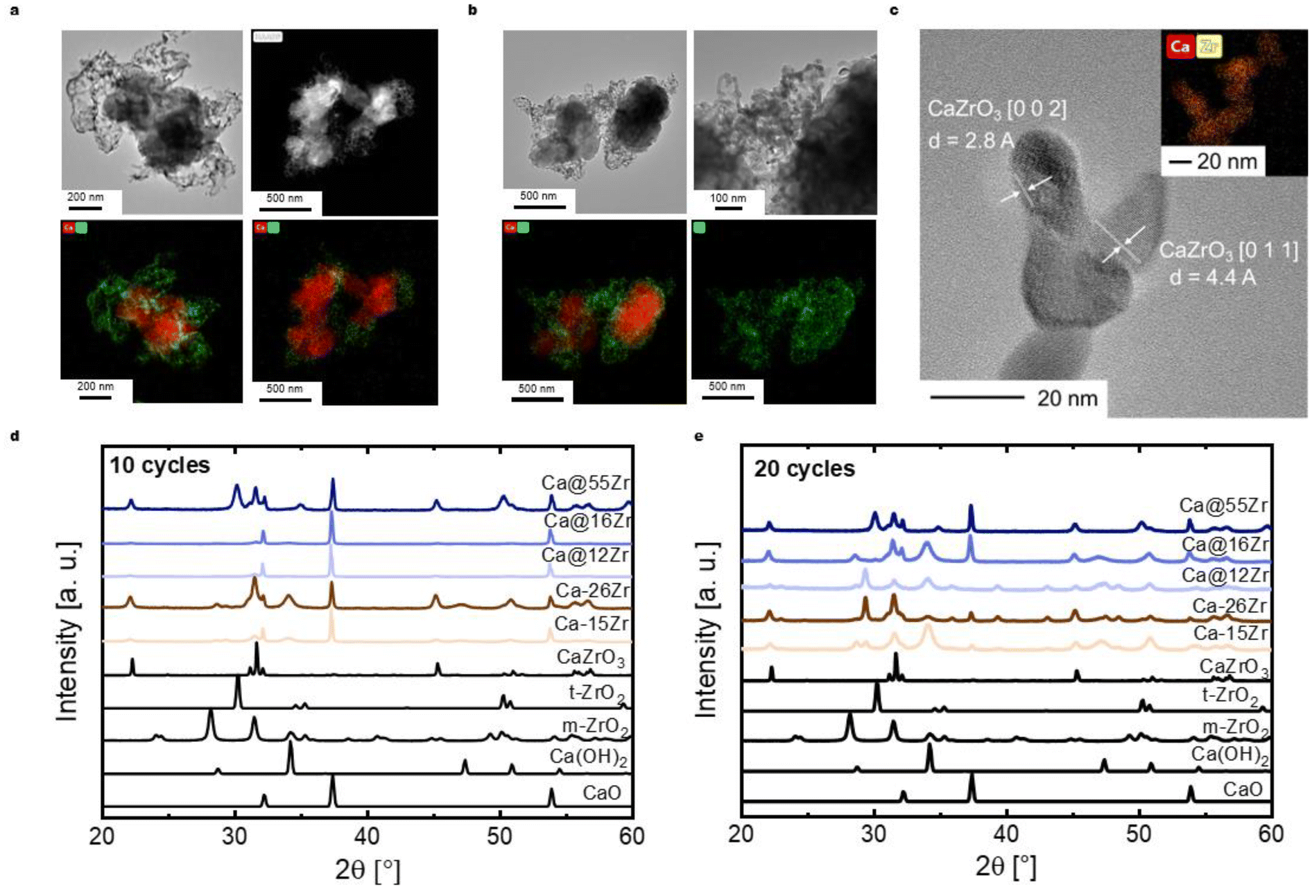 | ||
| Fig. 5 (a) (EDX-)TEM analysis of the most effective yolk–shell-structured sorbent Ca@12Zr after 10 carbonation–calcination cycles, (b) (EDX-)TEM analysis of the core–shell-structured sorbent Ca–26Zr, (c) high-resolution TEM micrograph and EDX mapping of the dendritic structures observed for all zirconia-stabilized sorbents (here: Ca@16Zr) and XRD patterns of the zirconia-stabilized sorbents after (d) 10 carbonation–calcination cycles as well as (e) 20 carbonation–calcination cycles. | ||
On the other hand, electron microscopy-based analysis of the core–shell sorbent Ca–26Zr after 10 cycles shows large CaO agglomerates surrounded by a Zr-containing layer (Fig. 5b). These particles also exhibited Zr-containing dendritic structures covering the surface of the CaO particles. EDX-TEM shows that the Zr coating is in intimate contact with the CaO surface, indicative of the formation of the Ca–Zr mixed phase. In addition, Ca–15Zr (Fig. S5c†) showed enlarged (i.e. sintered) CaO particles with dendritic coating structures at the surface. Indeed, cycled Ca–15Zr does not feature a homogeneous coating around CaO particles anymore. To conclude, a yolk–shell-structured architecture protected the single CaO nanoparticles from sintering more effectively than a core–shell-structured morphology. We expect the ZrO2- (or CaZrO3-) shell to act as a physical barrier against sintering between single CaO nanoparticles, reducing in turn sintering,6,29,53 whereby the yolk–shell architecture seems to be more effective in reducing the interfacial area between the individual CaO nanoparticles. Further, the high porosity of the yolk–shell-structured morphology allowed for a fast transport of CO2 to the surface of the CaO particles. In contrast, for core–shell-type particles the intimate contact between zirconia and CaO led to the formation of a thick Zr-containing shell (likely CaZrO3, see below) that reduced the rate of CO2 uptake by creating diffusional resistance for CO2. The formation of CaZrO3 over cycling will be discussed below.
3.6 Delay in CaZrO3 formation during cycling in yolk–shell-structured sorbents
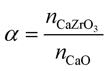
XRD measurements of the as-prepared sorbents showed that the yolk–shell architecture reduces the degree of CaZrO3 formation compared to the core–shell morphologies. In the following we track the formation of CaZrO3 over repeated carbonation–calcination cycling and its correlation with sorbent deactivation.The XRD patterns of zirconia-stabilized yolk–shell and core–shell sorbents after 10 and 20 cycles are shown in Fig. 5d and e, respectively. Using Rietveld analysis (Table S1†), we estimate the fraction of CaZrO3 in the different materials and define the parameter α, i.e. the molar ratio of CaZrO3 to the total molar amount of CaO in the as-synthesized sorbent (see Table 2):
 | (3) |
| Sorbent | Ratio as-prepared | Ratio after 10 cycles | Ratio after 20 cycles |
|---|---|---|---|
| Ca–15Zr | 0.07 | 0.08 | 0.08 |
| Ca–26Zr | 0.21 | 0.20 | 0.24 |
| Ca@16Zr | <0.01 | 0.03 | 0.09 |
| Ca@12Zr | <0.01 | 0.04 | 0.07 |
In the core–shell sorbent Ca–15Zr the ratio α increased slightly from 0.07 (as-prepared) to 0.08 after 20 cycles. This small increase is however within the accuracy of the experiment. Therefore, we conclude that in Ca–15Zr most, if not all, of the CaZrO3 phase already formed after the initial calcination step. For Ca–26Zr, α was 0.21 (as-prepared), 0.20 (10 cycles) and 0.24 (20 cycles). Hence, also for Ca–26Zr most of the Zr is in the form of CaZrO3 after the initial calcination step. The intimate contact between Ca and Zr-containing phases in the core–shell-based architectures leads to the rapid formation of a CO2-capture-inactive CaZrO3 layer around CaO particles (as also evidenced by TEM analysis). Hence, the deactivation of the core–shell sorbents over repeated carbonation–calcination cycles is not driven by the additional formation of CaZrO3. Instead, it is very likely that deactivation is due to the sintering of the individual CaO particles and an increase in the density (and thickness) of the CaZrO3 layer itself (as a result of sintering). This reduces the size of the active surface area and decreases the effective diffusivity of CO2.
The XRD patterns of the yolk–shell sorbents after 10 and 20 cycles (Fig. 5d and e) show the presence of CaZrO3. The values of α after 10 cycles are 0.03 and 0.04 for Ca@16Zr and Ca@12Zr, respectively. Hence, for yolk–shell-structured sorbents the fraction of CaZrO3 increased significantly with cycle number (the as-prepared materials have α < 0.01). After 20 cycles, α increased further to 0.09 for Ca@16Zr and 0.07 for Ca@12Zr, indicating a continuing formation of CaZrO3 during cycling. In addition, a small peak due to t-ZrO2 (approximately 1 wt%) was observed for Ca@16Zr (20 cycles). This continuing formation of CO2-capture-inactive CaZrO3 for the yolk–shell-structured materials, in particular for Ca@12Zr, is one explanation for their decreasing CO2 uptake with cycle number (∼40% decrease from the 1st to 20th cycle for Ca@16Zr), yet sintering of CaO nanoparticles must also contribute to the decay in the CO2 uptake for Ca@16Zr. For Ca@12Zr on the other hand, the formation of CaZrO3 would result in a theoretical loss of approximately 6 wt% of the initially available CaO. At the same time, Ca@12Zr shows a drop in the cyclic CO2 uptake from the 1st to the 20th cycle of ∼8%, i.e. for Ca@12Zr the loss of reactive CaO due to CaZrO3 formation accounts to ∼75% of the decay in CO2 uptake. Hence, the yolk–shell-structured architecture of Ca@12Zr largely prevented sintering of the CaO nanoparticles, making the loss of reactive CaO through the formation of CaZrO3 the dominating deactivation mechanism. The formation of CaZrO3 is likely a result of the partial loss of the yolk–shell-type structure during cycling, as evidenced in our TEM analysis (Fig. 5a). Hence, the sacrificial template can reduce the amount of CaZrO3 formation during the first cycles, but cannot prevent entirely the contact between CaO and ZrO2.
4. Conclusion
In this work, we designed and synthesized yolk(CaO)–shell(ZrO2)-structured sorbents for CO2 capture. The nanostructured materials developed here exceeded the CO2 uptake of the bare CaO nanoparticle benchmark by more than 250% after 20 carbonation–calcination cycles. Comparing the performance of yolk–shell-structured sorbents with that of core–shell structures for which there is an intimate contact between the stabilizer (ZrO2) and CaO, we demonstrate that the yolk–shell-structured materials have a significantly reduced rate of deactivation. The void space between the stabilizer shell and CaO nanoparticle, introduced by a sacrificial carbonaceous template, is crucial to increase the effective diffusivity of CO2, delay the formation of CaZrO3 and stabilize the individual CaO nanoparticles against sintering. The yolk–shell-structured sorbent with a ZrO2 content of 12 wt% performs best and in this material the gradual formation of CaZrO3 with cycle number is the main deactivation mechanism, accounting for 75% of the overall decay in the cyclic CO2 uptake over 20 cycles. Hence, yolk–shell architectures can successfully mitigate sintering, but need to be optimized further to reduce the loss of active CaO. Another important aspect for future work is to develop strategies to maintain the initial yolk–shell-type structure during high-temperature pretreatment and cycling. Furthermore, the use of stabilizers that do not form a mixed phase with CaO under calcium looping conditions, e.g. magnesium oxide, may help to provide a yolk–shell architecture with even higher CO2 uptakes and prolonged stability.Author contributions
M. K. and C. R. M. conceived and planned the project. M. K. performed the material synthesis, performance characterization, structural characterization as well as SEM analysis. A. O. performed the material synthesis, performance characterization and structural characterization. J. N. performed the material synthesis and structural characterization. A. L. and A. K. performed (EDX-)TEM characterization. M. K. wrote the manuscript with input from all authors. F. D. and A. H. B. revised the manuscript. C. R. M. supervised the project, wrote and revised the manuscript.Conflicts of interest
The authors have no conflicts of interest to declare.Acknowledgements
This research is based on funding by the European Research Council (ERC) under the European Union's Horizon 2020 research and innovation program under grant agreement number 819573. We also acknowledge Fondation Claude & Giuliana for financial support. A. O. acknowledges funding by the Swiss Exchange Mobility Program (SEMP) of ETH Zürich and RWTH Aachen University. The authors acknowledge the help of the ScopeM team at ETH Zurich for SEM, TEM and EDX analysis.References
- R. K. Pachauri and L. A. Meyer, Climate Change 2014: Synthesis Report. Contribution of Working Groups I, II and III to the Fifth Assessment Report of the Intergovernmental Panel on Climate Change, 2014.
- NASA, Local CO2 concentration at Mauna Loa Observatory, Hawaii, USA, 2020 Search PubMed.
- G. Krinner, et al., Long-term climate change: Projections, commitments and irreversibility. Climate Change 2013 the Physical Science Basis: Working Group I Contribution to the Fifth Assessment Report of the Intergovernmental Panel on Climate Change, 2013, vol. 9781107057.
- D. P. Hanak, E. J. Anthony and V. Manovic, A review of developments in pilot-plant testing and modelling of calcium looping process for CO2 capture from power generation systems, Energy Environ. Sci., 2015, 8, 2199–2249 RSC.
- A. M. Kierzkowska, R. Pacciani and C. R. Müller, CaO-based CO2 sorbents: From fundamentals to the development of new, highly effective materials, ChemSusChem, 2013, 6, 1130–1148 CrossRef CAS PubMed.
- M. T. Dunstan, F. Donat, A. H. Bork, C. P. Grey and C. R. Müller, CO2 Capture at Medium to High Temperature Using Solid Oxide-Based Sorbents: Fundamental Aspects, Mechanistic Insights, and Recent Advances, Chem. Rev., 2021, 121, 12681–12745 CrossRef CAS PubMed.
- C. H. Yu, C. H. Huang and C. S. Tan, A review of CO2 capture by absorption and adsorption, Aerosol Air Qual. Res., 2012, 12, 745–769 CrossRef CAS.
- G. Manzolini, et al., Economic assessment of novel amine based CO2 capture technologies integrated in power plants based on European Benchmarking Task Force methodology, Appl. Energy, 2015, 138, 546–558 CrossRef CAS.
- I. M. Bernhardsen and H. K. Knuutila, A review of potential amine solvents for CO2 absorption process: Absorption capacity, cyclic capacity and pKa, Int. J. Greenhouse Gas Control, 2017, 61, 27–48 CrossRef CAS.
- C. Luo, et al., Morphological Changes of Pure Micro- and Nano-Sized CaCO3 during a Calcium Looping Cycle for CO2 Capture, Chem. Eng. Technol., 2012, 35, 547–554 CrossRef CAS.
- Z. S. Li, N. S. Cai and Y. Y. Huang, Effect of preparation temperature on cyclic CO2 capture and multiple carbonation-calcination cycles for a new Ca-based CO2 sorbent, Ind. Eng. Chem. Res., 2006, 45, 1911–1917 CrossRef CAS.
- R. Barker, The reversibility of the reaction CaCO3 ⇄ CaO + CO2, J. Appl. Chem. Biotechnol., 2007, 23, 733–742 CrossRef.
- K. Wang, P. T. Clough, P. Zhao and E. J. Anthony, Synthesis of highly effective stabilized CaO sorbents via a sacrificial N-doped carbon nanosheet template, J. Mater. Chem. A, 2019, 7, 9173–9182 RSC.
- A. Kurlov, et al., Mechanochemically Activated, Calcium Oxide-Based, Magnesium Oxide-Stabilized Carbon Dioxide Sorbents, ChemSusChem, 2016, 9, 2380–2390 CrossRef CAS PubMed.
- S. M. Kim, et al., In Situ XRD and Dynamic Nuclear Polarization Surface Enhanced NMR Spectroscopy Unravel the Deactivation Mechanism of CaO-Based, Ca3Al2O6-Stabilized CO2 Sorbents, Chem. Mater., 2018, 30(4), 1344–1352 CrossRef CAS.
- C. Chi, Y. Li, W. Zhang and Z. Wang, Synthesis of a hollow microtubular Ca/Al sorbent with high CO2 uptake by hard templating, Appl. Energy, 2019, 251, 113382 CrossRef CAS.
- Y. Xu, et al., Characteristics and performance of CaO-based high temperature CO2 sorbents derived from a sol-gel process with different supports, RSC Adv., 2016, 6, 79285–79296 RSC.
- M. Broda and C. R. Müller, Sol-gel-derived, CaO-based, ZrO2-stabilized CO2 sorbents, Fuel, 2014, 127, 94–100 CrossRef CAS.
- S. M. Kim, A. Armutlulu, A. M. Kierzkowska and C. R. Müller, Inverse Opal-Like, Ca3Al2O6-Stabilized, CaO-Based CO2 Sorbent: Stabilization of a Highly Porous Structure To Improve Its Cyclic CO2 Uptake, ACS Appl. Energy Mater., 2019, 2, 6461–6471 CrossRef CAS.
- J. Blamey, V. Manovic, E. J. Anthony, D. R. Dugwell and P. S. Fennell, On steam hydration of CaO-based sorbent cycled for CO2 capture, Fuel, 2015, 150, 269–277 CrossRef CAS.
- M. Krödel, A. Landuyt, P. M. Abdala and C. R. Müller, Mechanistic Understanding of CaO-Based Sorbents for High-Temperature CO2 Capture: Advanced Characterization and Prospects, ChemSusChem, 2020, 13, 6259–6272 Search PubMed.
- A. Kurlov, A. M. Kierzkowska, T. Huthwelker, P. M. Abdala and C. R. Müller, Na2CO3-modified CaO-based CO2 sorbents: The effects of structure and morphology on CO2 uptake, Phys. Chem. Chem. Phys., 2020, 22, 24697–24703 RSC.
- Y. Xu, et al., Structure and surface insight into a temperature-sensitive CaO-based CO2 sorbent, Chem. Eng. J., 2022, 435, 134960 CrossRef CAS.
- M. Broda, A. M. Kierzkowska and C. R. Müller, Application of the sol-gel technique to develop synthetic calcium-based sorbents with excellent carbon dioxide capture characteristics, ChemSusChem, 2012, 5, 411–418 CrossRef CAS PubMed.
- H. Lu, A. Khan and P. G. Smirniotis, Relationship between structural properties and CO2 capture performance of CaO-based sorbents obtained from different organometallic precursors, Ind. Eng. Chem. Res., 2008, 47, 6216–6220 CrossRef CAS.
- M. A. Naeem, et al., Optimization of the structural characteristics of CaO and its effective stabilization yield high-capacity CO2 sorbents, Nat. Commun., 2018, 9, 1–11 CrossRef CAS PubMed.
- W. Liu, et al., Synthesis of sintering-resistant sorbents for CO2 capture, Environ. Sci. Technol., 2010, 44, 3093–3097 CrossRef CAS PubMed.
- L. Zhang, Y. Lu and M. Rostam-Abadi, Sintering of calcium oxide (CaO) during CO2 chemisorption: A reactive molecular dynamics study, Phys. Chem. Chem. Phys., 2012, 14, 16633–16643 RSC.
- K. S. Sultana, D. T. Tran, J. C. Walmsley, M. Rønning and D. Chen, CaO Nanoparticles Coated by ZrO2 Layers for Enhanced CO2 Capture Stability, Ind. Eng. Chem. Res., 2015, 54, 8929–8939 CrossRef CAS.
- M. Zhao, et al., Durability of CaO-CaZrO3 sorbents for high-temperature CO2 capture prepared by a wet chemical method, Energy Fuels, 2014, 28, 1275–1283 CrossRef CAS.
- J. Cai, S. Wang and C. Kuang, ScienceDirect A Modified Random Pore Model for Carbonation Reaction of CaO-based limestone with CO 2 in Different Calcination-carbonation Cycles, Energy Procedia, 2017, 105, 1924–1931 CrossRef CAS.
- A. Di Giuliano, K. Gallucci and P. U. Foscolo, Determination of Kinetic and Diffusion Parameters Needed to Predict the Behavior of CaO-Based CO2 Sorbent and Sorbent-Catalyst Materials, Ind. Eng. Chem. Res., 2020, 59, 6840–6854 CrossRef CAS.
- Y. Li, Z. Li, H. Wang and N. Cai, CaO carbonation kinetics determined using micro-fluidized bed thermogravimetric analysis, Fuel, 2020, 264, 116823 CrossRef CAS.
- H. Sun, et al., Fundamental studies of carbon capture using CaO-based materials, J. Mater. Chem. A, 2019, 7, 9977–9987 RSC.
- D. Alvarez and J. C. Abanades, Pore-size and shape effects on the recarbonation performance of calcium oxide submitted to repeated calcination/recarbonation cycles, Energy Fuels, 2005, 19, 270–278 CrossRef CAS.
- S. K. Bhatia and D. D. Perlmutter, Effect of the product layer on the kinetics of the CO2−lime reaction, AIChE J., 1983, 29, 79–86 CrossRef CAS.
- Z. S. Li, F. Fang, X. Y. Tang and N. S. Cai, Effect of temperature on the carbonation reaction of CaO with CO2, Energy Fuels, 2012, 26, 2473–2482 CrossRef CAS.
- G. Grasa, R. Murillo, M. Alonso and J. C. Abanades, Application of the random pore model to the carbonation cyclic reaction, AIChE J., 2009, 55(5), 1246–1255 CrossRef CAS.
- D. Alvarez and J. Carlos Abanades, Determination of the critical product layer thickness in the reaction of CaO with CO2, Ind. Eng. Chem. Res., 2005, 44, 5608–5615 CrossRef CAS.
- N. Mahinpey, M. H. Sedghkerdar, A. Aqsha and A. H. Soleimanisalim, CO2 Capture Performance of Core/Shell CaO-Based Sorbent Using Mesostructured Silica and Titania in a Multicycle CO2 Capture Process, Ind. Eng. Chem. Res., 2016, 55, 4532–4538 CrossRef CAS.
- W. Peng, Z. Xu, C. Luo and H. Zhao, Tailor-Made Core-Shell CaO/TiO2-Al2O3 Architecture as a High-Capacity and Long-Life CO2 Sorbent, Environ. Sci. Technol., 2015, 49, 8237–8245 CrossRef CAS PubMed.
- S. Zhang and X. Li, Synthesis and characterization of CaCO3@SiO2 core-shell nanoparticles, Powder Technol., 2004, 141, 75–79 CrossRef CAS.
- C. Huang, M. Xu, X. Huai and Z. Liu, Template-Free Synthesis of Hollow CaO/Ca2SiO4 Nanoparticle as a Cyclically Stable High-Capacity CO2 Sorbent, ACS Sustainable Chem. Eng., 2021, 9, 2171–2179 CrossRef CAS.
- X. Fang, et al., Precisely controlled resorcinol–formaldehyde resin coating for fabricating core–shell, hollow, and yolk–shell carbon nanostructures, Nanoscale, 2013, 5, 6908–6916 RSC.
- P. M. Arnal, C. Weidenthaler and F. Schüth, Highly monodisperse zirconia-coated silica spheres and zirconia/silica hollow spheres with remarkable textural properties, Chem. Mater., 2006, 18, 2733–2739 CrossRef CAS.
- X. Zhang, et al., Methane decomposition and carbon deposition over Ni/ZrO2 catalysts: Comparison of amorphous, tetragonal, and monoclinic zirconia phase, Int. J. Hydrogen Energy, 2019, 44, 17887–17899 CrossRef CAS.
- D. S. S. Padovini, D. S. L. Pontes, C. J. Dalmaschio, F. M. Pontes and E. Longo, Facile synthesis and characterization of ZrO2 nanoparticles prepared by the AOP/hydrothermal route, RSC Adv., 2014, 4, 38484–38490 RSC.
- C. Dwivedi, et al., Resorcinol-formaldehyde coated XAD resin beads for removal of cesium ions from radioactive waste: Synthesis, sorption and kinetic studies, RSC Adv., 2012, 2, 5557–5564 RSC.
- D. F. Molina-Campos, R. A. Fonseca-Correa, D. P. Vargas-Delgadillo, L. Giraldo and J. C. Moreno-Piraján, Data for the synthesis of resorcinol–formaldehyde aerogels in acidic and basic media, Data Brief, 2017, 12, 409–417 CrossRef PubMed.
- Z. Zhou, P. Xu, M. Xie, Z. Cheng and W. Yuan, Modeling of the carbonation kinetics of a synthetic CaO-based sorbent, Chem. Eng. Sci., 2013, 95, 283–290 CrossRef CAS.
- H. Wang, Z. Li, Y. Li and N. Cai, Reduced-order model for CaO carbonation kinetics measured using micro-fluidized bed thermogravimetric analysis, Chem. Eng. Sci., 2021, 229, 116039 CrossRef CAS.
- R. H. Borgwardt, K. R. Bruce and J. Blake, An Investigation of Product-Layer Diffusivity for CaO Sulfation, Ind. Eng. Chem. Res., 1987, 26(10), 1993–1998 CrossRef CAS.
- P. Sun, J. R. Grace, C. J. Lim and E. J. Anthony, The effect of CaO sintering on cyclic CO2 capture in energy systems, AIChE J., 2007, 53, 2432–2442 CrossRef CAS.
Footnote |
| † Electronic supplementary information (ESI) available. See DOI: https://doi.org/10.1039/d2nr04492g |
| This journal is © The Royal Society of Chemistry 2022 |