Multiplexed printed sensors for in situ monitoring in bivalve aquaculture

Shuo-En Wu a, Napasorn Phongphaew b, Yichen Zhai c, Lulu Yao a, Hsun-Hao Hsu d, Alan Shiller e, Jason D. Azoulay f and Tse Nga Ng *ab
aMaterials Science Engineering Program, University of California San Diego, La Jolla, CA 92093, USA. E-mail: tnn046@ucsd.edu
bDepartment of Electrical and Computer Engineering, University of California San Diego, La Jolla, CA 92093, USA
cDepartment of Mechanical and Aerospace Engineering, University of California San Diego, La Jolla, CA 92093, USA
dDepartment of Applied Chemistry, National Yang Ming Chiao Tung University, Hsinchu 30010, Taiwan
eDivision of Marine Science, University of Southern Mississippi, Stennis Space Center, MS 39529, USA
fSchool of Polymer Science and Engineering, The University of Southern Mississippi, Hattiesburg, MS 39406, USA

Received 10th August 2022 , Accepted 18th October 2022

First published on 18th October 2022


Abstract

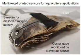
Non-intrusive sensors that can be attached to marine species offer opportunities to study the impacts of environmental changes on their behaviors and well-being. This work presents a thin, flexible sensor tag to monitor the effects of dissolved oxygen and salinity on bivalve gape movement. The measurement range studied was 0.5–6 ppm for the dissolved oxygen sensor and 4–40 g kg−1 for the salinity sensor. The curvature strain sensor based on electrodeposited semiconducting fibers enabled measurements of an oyster's gape down to sub-mm displacement. The multiplexed sensors were fabricated by low-cost techniques, offering an economical and convenient platform for aquaculture studies.


I. Introduction

Understanding the influence of environmental changes on marine life is important to ecological sustainability and aquaculture. For example, rising temperatures reduce the solubility of oxygen in water, leading to more frequent and intense occurrences of hypoxia that devastate aquatic life.1 Massive algae blooms have exacerbated hypoxia in aquafarms and resulted in poor yields and shellfish toxicity2 that distress global oyster industries, which are worth well over $6 billion US dollars annually.3 As reef-building organisms, oysters also generate habitat for other environmentally and commercially important organisms such as various fish and crustaceans.4 Compact, non-intrusive sensors attachable to these marine species are highly desirable for gathering local environmental parameters to correlate organism physiology, migration behaviors, and compensatory responses to adverse conditions.5,6

Building on recent advances in flexible aquatic sensors,7–10 this work demonstrates a printed multi-modal sensor tag suitable for in situ monitoring in complex marine environments. Specifically, the multiplexed sensor tag enables tracking of bivalve gape responses to local changes in dissolved oxygen (DO) concentration and salinity to aid in understanding environmental impacts on oyster behaviors. Sensing fluctuations in DO and salinity are essential because these parameters cause stress regulation and critically affect bivalve growth and mortality.11–14 In addition, bivalve closure has been shown to provide early warning of detrimental conditions for shellfish populations.15 However, prior works on gape measurements were conducted with complex instrumentation such as a magnetic Hall probe16,17 or limited to a binary classification between open or closed states.15 Here we developed a sensitive, miniaturized curvature sensor to monitor gaping activities down to sub-millimeter displacement. The integrated sensor tag with three sensing modalities is flexible and small with an area <3 cm2 for non-intrusive placement onto an individual bivalve and can facilitate widespread monitoring at low costs.

The fabrication of our prototype used inexpensive techniques including a digital blade-cutter, lamination, stencil printing, and electrodeposition. The DO and salinity sensor electrodes were cut from flexible graphite foils that are stable in seawater when compared to silver inks used in additive printing.18–21 The curvature sensor was based on an organic electrochemical transistor (OECT), and the sensing channel semiconductor was electrodeposited by an alternating current (AC) waveform22,23 that controlled micro-fiber formation with nanoporous structures. The robust fibers offer the advantage of operation in seawater without encapsulation. The sensors were connected through a multiplexer circuit to a handheld potentiostat to achieve a portable system. A proof-of-concept demonstration was conducted using the integrated sensor tag in laboratory trials to monitor an oyster's gape, as well as ambient salinity and DO concentration down to oxygen concentrations associated with hypoxia. The thin, flexible design enables local measurements in confined spaces that are not accessible using conventional bulky probes.

II. Results and discussion

In the schematic shown in Fig. 1, the concentric rings represent electrodes for DO and salinity detection. Such arrangement minimized the electrodes’ footprint and used the same reference and counter electrodes for both DO and salinity measurements. The seawater sample contained the analytes and also acted as the electrolyte in the electrochemical measurements. Of the two working electrodes, one was for sensing the DO level based on the oxygen reduction reaction, and the other was used to measure the seawater conductivity, which at a constant temperature is proportional to its salinity in grams of salt per kilogram of water. The potentials of the working electrodes (WE) were controlled with respect to the reference electrode (REF), and the corresponding currents were collected through the counter electrode (CE). Next to the circular electrodes, an OECT structure was patterned to function as the curvature sensor to monitor gape movements. The drain and gate electrodes were controlled by the two WE channels on the potentiostat, while the source electrode was connected to the REF and CE channels tied together for current read-out. The device dimensions and fabrication procedures are explained in details in the Experimental section and ESI Fig. S1.
image file: d2nr04382c-f1.tif
Fig. 1 Schematics and photographs of the printed multiplexed sensors for monitoring bivalve gape response to environmental variables of dissolved oxygen and salinity.

The photographs in Fig. 1 show all three sensors integrated on the flexible poly(ethylene terephthalate) (PET) substrate. The tag was wrapped around the oyster hinge and externally attached to the shell using adhesive without the need to insert anything into the gape since that would be invasive to the organism. The connections to the sensors were directed into the multiplexer circuit, which controlled the sequential read-out of the three sensors by the potentiostat. The timing diagram in Fig. 2 shows the switching of multiplexer control signals (MUX) to each sensor. When the MUX signal was turned on at the selected sensor, the bias on the WE channel was passed to the active device, and the current at the CE channel was measured. In this work, the MUX on-period was 10 seconds, and we used the readout data near the end of each period when transient current spikes from voltage switching settled and the sensor was in a steady state for accurate detection.


image file: d2nr04382c-f2.tif
Fig. 2 Timing diagram of control and measurement signals for three sensors, under sequential readout switched by the multiplexer circuit interfacing with the potentiostat. The solid dots indicate steady-state measurement points near the end of each sampling period.

II.A. Curvature sensor based on an OECT

To monitor bivalve gape movements, this work developed an OECT with nanoporous semiconducting fibers that are advantageous for bending curvature measurements. Compared to other pressure24–26 or strain sensors27–31 fabricated by coating films, the electrodeposition process to form semiconducting fibers facilitated their inherent alignment in that the fibers would grow along the direction of an applied electric field until they bridge the electrodes. Then the semiconducting fibers could be aligned with the bending curvature to maximize their structural deformation and in turn their change in resistance with bending strain. We chose the OECT structure over simple resistor configuration, because the gate bias allowed amplification of current changes to increase the device sensitivity.

Fig. 3a shows the chemical structure of the polymer poly(3,4-ethylenedioxythiophone)-hexafluorophosphate (PEDOT:PF6), which was electrodeposited using an AC waveform23 applied across the source and drain electrodes in a solution of monomers and salt mixture (details described in the Experimental section). In brief, the 3,4-ethylenedioxythiophene (EDOT) monomers were oxidized forming radical cations, which were charge balanced by PF6 anions. The sequential reaction with other EDOT+ monomers enabled the growth of the polymer chain following the electric field lines, with fiber tip growth more kinetically favorable because of stronger local field compared to flat edges of electrodes. The fiber morphology depended on the amplitude and frequency of the electrodeposition voltage waveform, as shown in ESI Fig. S2. A waveform frequency higher than 50 Hz resulted in more bifurcation and branching in the fibers, but low frequency less than 5 Hz led to dense and wide strips. We used a triangular waveform of 12.5 Hz and ±10 V to form thin fibers with a porous surface as seen in the scanning electron microscopy image in Fig. 3a. The OECT channel conductance was measured to be 40 mS cm−1 and reproducible over multiple deposition runs (ESI Fig. S2).


image file: d2nr04382c-f3.tif
Fig. 3 (a) Schematics of PEDOT:PF6 formed by AC electrodeposition. Optical microscope and scanning electron microscopy image of PEDOT:PF6 fibers. (b) Schematics of an organic electrochemical transistor with seawater or hydrogel as the electrolyte. (c) Transfer and (d) output characteristic of a PEDOT:PF6 electrochemical transistor in the flat state. (e) Source–drain current versus time under various bending radii, with an illustration showing the experimental configuration for calibrating the curvature sensor. (f) Transconductance and (g) ratio of current change as a function of bending curvature. Red line indicates a fit to eqn (1). Error bars accounted for the uncertainty level in the baseline drift. For parts (e) and (g), VDS = −0.5 V, VGS = −0.2 V.

The current–voltage characteristics of the PEDOT:PF6 OECT were taken in simulated seawater (Instant Ocean®) or when covered by a hydrogel electrolyte with a seawater-equivalent ionic strength of 0.6 M NaCl. There was negligible difference between the two measurements (ESI Fig. S3a). In Fig. 3b–g, characterization was carried out with the hydrogel for convenience, while the data in all other figures were measured with the device submerged in seawater. The OECT operated in depletion mode, and applying positive gate bias de-doped the semiconductor and reduced the channel conductance as seen in Fig. 3c and d. The maximum transconductance was gm = 0.88 mS, and the device on/off ratio was ∼500. The mobility-capacitance product (μC*) was extracted23 to be 1.24 F cm−1 V−1 s−1, assuming a geometry of fiber width w = 75 μm, channel gap L = 250 μm, and fiber channel number n = 2. In OECTs, it is preferable that the tunable channel resistance exceeds all other elements combined, including contact resistance32,33 between polymer/electrode interfaces and wire connections. The contact resistance of our OECT was estimated by fitting to the Y-function model34,35 to be 240 Ω, similar to the value extracted by electrochemical impedance spectroscopy (ESI Fig. S3b and S3c). Meanwhile, the OECT channel resistance was ∼1 kΩ at the gate bias of VGS = 0 V. Thus, the resistance across the channel was higher than at contacts, which was favorable for strain sensing to obtain large resistance change with deformation of channel materials.

Fig. 3e displays the OECT source–drain current IDS decreased as the substrate was bent to tighter radii of curvature from r = 9 cm to 2 cm, corresponding to the curvature 1/r = 0.11 cm−1 to 0.5 cm−1, respectively. The sensor current was reproducible at different bending speeds from 0.5 cm s−1 to 5 cm s−1 (ESI Fig. S4a). The IDS exhibited excellent recovery after bending cycles, and the device in a flat state returned to the baseline with only a small drift of <6% over 6 min, potentially due to bias stress36,37 that can be further reduced by changing the duty cycle or compensated by drift subtraction. While the channel current IDS was clearly influenced by bending strain, the gate leakage (IGS) was a thousand-fold lower than IDS and showed no apparent response to bending (ESI Fig. S4b). The steady IGS confirmed that strain in the hydrogel, graphite electrodes, and interconnects did not induce significant current response, and only the semiconducting fibers were the major contributor to the IDS change upon bending. In Fig. 3f, the transconductance was reduced with increasing curvature, comparable to other strain measurements on PEDOT films.27,38 This trend was attributed to percolation effects, that the applied strain stretches the semiconductor, disrupts conductive paths, and hence decreases the transconductance.

Fig. 3g provides the calibration curves of OECT curvature sensors. The ratio ΔI/I0 was defined as the change in IDS between the baseline flat state and bent state [ΔI = IDS(0) −IDS(r)] divided by the baseline IDS, where IDS(0) = I0. The data ΔI/I0versus curvature 1/r was fitted to an empirical exponential equation

 
image file: d2nr04382c-t1.tif(1)
where fit parameters a = 0.153, b = 0.228 cm−1, c = 0.155, with an excellent coefficient of determination R2 = 0.97. The gauge factor GF indicating the device sensitivity was calculated by28
 
image file: d2nr04382c-t2.tif(2)
where ε is the surface strain and d is the substrate thickness equivalent to 130 μm in this work. The sensor GF was ∼35 when the radius of curvature was greater than 5 cm (1/r < 0.2 cm−1), and then GF dropped to 20 with bending radius below 5 cm. While this GF is not the state of the art, it falls within the range of most OECT strain sensors, and this un-encapsulated device provided the additional advantage of stable operation in seawater. The OECT curvature sensor also delivered a uniaxial strain response, with much lower resistance change when the applied strain was perpendicular to the fiber length as seen in ESI Fig. S4e. This result indicated the benefit of fiber alignment to the bending strain direction, maximizing the effect of structural deformation to enhance GF. In the following demonstration, because the oyster shell was typically 4–5 cm thick, the curvature measurement centered around r = 2.5 cm and the sensor GF was typically 20 in this work.

II.B. Salinity and dissolved oxygen (DO) sensors based on amperometry

The salinity of seawater is proportional to the amount of sodium chloride dissolved in the sample at a constant temperature and can be determined from ionic conductivity measurements. Here the salinity sensor detected the ionic current Isalinity through seawater samples using graphite electrodes (WE and CE in Fig. 1) with a bias of −0.2 V between them. The data in Fig. 4 was collected through the multiplexer controlling the potentiostat. In Fig. 4a as more salt was added to the sample, the change in Isalinity was recorded simultaneously alongside a commercial multimeter (Hanna model #HI98194). The calibration of Isalinityversus salinity readings from the commercial meter is shown in Fig. 4b at the temperature of 23 °C. The sensitivity was 0.013 μA cm−2 per g kg−1. The measured noise standard deviation in our multiplexed system was σ = 3.5 nA (ESI Fig. S5). Based on the signal-to-noise ratio, the salinity sensor showed a detection limit of 4.3 g kg−1 [detection limit = 3.3 × σ/S, where is the noise standard deviation = 3.5 nA and S is the sensitivity = 2.68 nA per g kg−1]. Typical salinity in the ocean39 is 33–37 g kg−1, although oysters live in shallow coastal water where the salinity can be lower. Our sensor can cover the relevant range and was demonstrated to work from 4–40 g kg−1.
image file: d2nr04382c-f4.tif
Fig. 4 (a) Current measurement by the printed salinity sensor biased at −0.2 V (black) and readings from the commercial meter (blue) as the sample salinity was increased over time. The inset illustrates the ionic current between sensor electrodes. (b) Calibration characteristics showing the sensor current density versus salinity. (c) Current measurement by printed dissolved oxygen sensor biased at −0.8 V (black) and readings from the commercial meter (blue), as oxygen concentration and salinity were adjusted. The inset illustrates oxygen reduction reaction at the sensor working electrode. (d) Calibration characteristics showing the sensor current versus dissolved oxygen concentration at three levels of salinity.

For the DO sensor, since the detection mechanism was through oxygen reduction reactions (ORRs), the working electrode was electrodeposited with platinum Pt particles, in order for the Pt to catalyze the ORRs on the graphite electrode. The reaction current IDO was measured under a potential of −0.8 V with respect to the reference electrode of activated carbon. The change in IDO was recorded as the DO concentration was adjusted by gas purging, with simultaneous measurements by the commercial multimeter as seen in Fig. 4c. While adjusting DO, we checked the effect of salinity on DO sensor measurements. The sensitivity of DO sensor was 2.42 μA ppm−1 in Fig. 4d, with no significant interference from changing salinity between 7.5–28 g kg−1. Only when salinity exceeded 38 g kg−1 did the DO sensor response slightly increase due to higher background ionic current. The detection limit for this amperometric DO sensor was 0.5 ppm. The DO concentration lower than 2 ppm has often been defined as hypoxic,15 and the sensor here would be sufficient to monitor even severe hypoxia (DO < 0.6 ppm).

II.C. Using the integrated sensor tag to monitor environmental effects on oyster gape behavior

In Fig. 5a, the printed sensor tag was attached to an oyster in a laboratory tank, with simultaneous video recording of the oyster movement to validate the curvature sensor readout. The DO level in the tank was adjusted by purging with gas, and the presented data excluded the gas-purging periods to avoid artifacts from gas turbulence. The oyster was active in opening and closing its gape when the DO level was above 3 ppm, as indicated by the increasing fluctuation frequency and amplitude detected by the curvature sensor in Fig. 5b. This behavior is also clearly observable in the ESI Video V1. Such effect of DO on gaping behavior has been reported in prior work15,40 showing that oysters shut their gape under hypoxic conditions to lower their metabolism. In comparison to video-recording, the curvature sensor consumed much less power and can operate in the dark so as to not disturb the circadian cycle of the organisms.
image file: d2nr04382c-f5.tif
Fig. 5 (a) Photographs of oyster gape movement. (b) Changes in curvature tracking the oyster gape under different dissolved oxygen levels with data sampling at 1 Hz. (c) Measurements by the integrated sensor tag to monitor gape responses to environmental parameters of dissolved oxygen concentration and salinity, sampling at 0.016 Hz. The applied bias on OECT was VGS = −0.2 V and VDS = −0.5 V, while the salinity sensor was biased at −0.2 V and DO sensor at −0.8 V. The data in blue represent measurements taken with the commercial multimeter to confirm the accuracy of printed sensors.

Another observation period of over 80 minutes using the integrated sensor tag is shown in Fig. 5c, with the DO, salinity, and curvature measurements carried out in parallel. Fig. 5c presents the simultaneous real-time outputs of all three sensors, with the black data lines from each sensor (top: curvature sensor; middle: dissolved oxygen sensor; bottom: salinity sensor), and the blue data lines were from the commercial sensors nearby. The recordings were taken through the MUX switching with the timing sequence as shown in Fig. 2. Like the earlier trial, higher DO in the environment led to more oyster gape movement. The salinity level was not adjusted in this trial, and the salinity readings remained constant and unaffected by gas purging.

The readout channel for the curvature sensor had a noise level of 0.01 μA with the current signal centered at 52 μA. From this ratio of Inoise/I0 = 0.01/52 = 2 × 10⁻⁴, the noise around the curvature measurement was calculated by using eqn (1) to be 1/r ±0.002 cm−1. That is, for a case in which the measured ΔI/I0 = 0.136 corresponding to a curvature of 0.477 cm−1, the curvature accounting for noise uncertainty was 0.477 ± 0.002 cm−1. Thus, the upper bound of curvature 1/r was 0.479 cm−1 and lower bound was 0.475 cm−1, translating to radii of 2.088 mm and 2.105 mm, respectively. The curvature sensor was capable of distinguishing gape displacement down to sub-mm levels. While the long-term stability of the sensor tag will be assessed in future studies, the materials in this work have exhibited promising stability in other week-long studies in simulated marine environment10 or in saline culture medium.41

III. Conclusions

With the sensing performance summarized in Table 1, this work demonstrated the feasibility of monitoring multiple parameters through an integrated sensor system that is low-cost and enables in situ monitoring for bivalve aquaculture research. In addition to salinity and DO detection, the multiplexed setup offers the potential to easily add sensors for other environmental parameters such as pH and temperature. The sensor tag could be improved by integrating a temperature sensor that tracks the local variations in temperature and thus compensate the change in sensor outputs due to temperature effects. The curvature sensor based on electrodeposited semiconducting fibers was mechanically robust and remarkably stable in seawater without the need for encapsulation. The small, non-intrusive sensor tags do not take up much space and in the future can be adapted for field use and attached to multiple bivalves to facilitate group behavior studies. Upon accounting for the statistical variations in the sensors, if a high percentage of bivalves close their gapes, that might be a prominent indicator of severe environmental conditions. Overall, this report shared the design and fabrication processes to implement flexible electronics as compact data collection tools in marine studies.
Table 1 Performance summary of sensors in this work
Sensor Detection accuracy Detection limit Detection range Sensitivity Device size
Curvature ±0.5% 1 cm−1 0.11–0.5 cm−1 GF of 35 to 20 0.3 cm2
Salinity ±0.7 g kg−1 4.3 g kg−1 4–40 g kg−1 0.013 μA cm−2 per g kg−1 0.2 cm2
Dissolved oxygen ±0.2 ppm 0.5 ppm 0.5–6 ppm 2.42 μA ppm−1 0.32 cm2


IV. Experimental procedures

IV.A. Materials

The substrates were poly(ethylene terephthalate) (PET) of 5 mil (∼130 μm) thickness with lamination adhesive on the surface and were purchased from Immuson. Graphite foils were purchased from Emitac New Material Technology (16[thin space (1/6-em)]000 S cm−1 in conductivity, 16 μm thickness). A platinized carbon cloth was purchased from FuelCellStore (0.3 mg cm−2, 40% Pt). Instant super glue for attaching the sensor tag to the bivalve shell was purchased from Gorilla Glue. The other chemicals were purchased from Sigma-Aldrich and used as received. The preparation procedures of hydrogel electrolyte and activated carbon (AcC) slurry were based on our previous work.10 In brief, the hydrogel electrolyte was a mixture of 1 g xanthan gum powder with 10 mL of simulated seawater (instant ocean salt, 31 mg in 1 L of deionized water). The AcC slurry was prepared by mixing activated carbon powder (Kuraray Chemical YP50F) and polyvinylidene fluoride in 9[thin space (1/6-em)]:[thin space (1/6-em)]1 ratio, with n-methyl-2-pyrrolidone as the slurry solvent.

IV.B. Device fabrication

The design of concentric-ring electrodes for amperometric DO and salinity sensors minimized the device footprint. Each ring was separated by a gap of 125 μm from neighboring rings. The electrode patterns in ESI Fig. S1 were cut from graphite foils by a digital blade-cutter (Silhouette Cameo). The graphite cut-outs were laminated onto the PET substrate by pressing them together at 150 °C for ten seconds. Then AcC was deposited onto the surface of the reference electrode by stencil printing to increase electric double layer capacitance in the reference electrode for DO and salinity sensors. The gate electrode of the OECT was modified by stencil printing Ag/AgCl ink (Ercon part #E2414),42 which reduced the series resistance of the gate for an applied voltage to drop mainly across the electrolyte and semiconductor channel. The stencil-printed materials were dried at 85 °C for 20 minutes.

Subsequently, two electrodeposition processes were carried out, one on the working electrode of the DO sensor and the other on the OECT to form semiconducting fibers for the transistor channel. For the DO sensor, the reaction catalyst was platinum, and the working electrode surface was modified by electrodepositing platinum nanoparticles from a platinized carbon cloth (40%, Pt–C) through a linear sweep voltammetry scan, applying 1.2 to 0.8 V for five cycles scanning at −50 mV s−1 on the platinized carbon cloth.10 Electrodeposition of semiconducting fibers to bridge the OECT channel (250 μm in length) was done through a solution of 10 mM 3,4-ethylenedioxythiophene (EDOT) and 1 mM tetrabutylammonium hexafluorophosphate (TBAPF6) in propylene carbonate solvent. The deposition voltage was a triangular waveform of ±10 V switching at 12.5 Hz, applied between the two graphite source and electrodes. The deposition time was around 10 minutes until the deposition current reached saturation. Finally, the graphite interconnects were connected to aluminum wires through silver paste. The bonding area between the sensor tag and the aluminum wires was encapsulated by silicone elastomer (Ecoflex) to avoid contact between the wires and seawater during measurements.

IV.C. Multiplexer circuit and wiring

The circuit components included four 8-to-1 multiplexer chips (74HC4051) and the Nano-Arduino purchased from Sparkfun. The multiplexer channels were controlled by Nano-Arduino through three select-lines (S0, S1, and S2, connected to the Arduino analog outputs of A0, A1, and A2). The outputs of multiplexers were connected to a portable potentiostat (Metrohm μ300) for data acquisition. The 5 V used to power Nano-Arduino and multiplexers were supplied by computer. The multiplexer circuit was soldered on a small piece of gold-plated printed circuit board. The multiplexers served as digital switches between channels, controlled by a custom Arduino program shown in ESI Fig. S7.

IV.D. Device characterization

Electrical measurements were taken with electrometers (Keithley 2000) controlled by LabVIEW software or with a portable potentiostat (Metrohm μ300) controlled by DropView 8400. Cyclic voltammetry, linear sweep voltammetry, and electrochemical impedance spectroscopy were carried out using a benchtop potentiostat (BioLogic SP-200). Scanning electron microscopy images were taken with FEI microscope operating at 5 kV. In the bending measurements, the device curvature was adjusted by laying it on a printed mold with various radii of curvature (ESI Fig. S7); the mold was fabricated using the printer Raise3D N2 platform.43 The concentration of dissolved oxygen was adjusted by purging oxygen or nitrogen and monitored by a multimeter (Hanna model #HI98194) in real-time.

Conflicts of interest

The authors declare no conflict of interest.

Acknowledgements

This project was supported by Office of Naval Research award N00014-19-1-2687.

References

  1. D. Breitburg, L. A. Levin, A. Oschlies, M. Grégoire, F. P. Chavez, D. J. Conley, V. Garçon, D. Gilbert, D. Gutiérrez, K. Isensee, G. S. Jacinto, K. E. Limburg, I. Montes, S. W. A. Naqvi, G. C. Pitcher, N. N. Rabalais, M. R. Roman, K. A. Rose, B. A. Seibel, M. Telszewski, M. Yasuhara and J. Zhang, Declining Oxygen in the Global Ocean and Coastal Waters, Science, 2018, 359(6371), 46 CrossRef CAS.
  2. P. Visciano, M. Schirone, M. Berti, A. Milandri, R. Tofalo and G. Suzzi, Marine Biotoxins: Occurrence, Toxicity, Regulatory Limits and Reference Methods, Front. Microbiol., 2016, 7(July), 1051 CrossRef PubMed.
  3. S. J. Nowland, W. A. O'Connor, M. W. J. Osborne and P. C. Southgate, Current Status and Potential of Tropical Rock Oyster Aquaculture, Rev. Fish. Sci. Aquacult., 2020, 28(1), 57–70 CrossRef.
  4. M. K. La Peyre, D. Aguilar Marshall, L. S. Miller and A. T. Humphries, Oyster Reefs in Northern Gulf of Mexico Estuaries Harbor Diverse Fish and Decapod Crustacean Assemblages: A Meta-Synthesis, Front. Mar. Sci., 2019, 6(October), 666 CrossRef.
  5. N. E. Hussey, S. T. Kessel, K. Aarestrup, S. J. Cooke, P. D. Cowley, A. T. Fisk, R. G. Harcourt, K. N. Holland, S. J. Iverson, J. F. Kocik, J. E. M. Flemming and F. G. Whoriskey, Aquatic Animal Telemetry: A Panoramic Window into the Underwater World, Science, 2015, 348(6240), 1255642 CrossRef PubMed.
  6. H. Chung, J. Lee and W. Y. Lee, A Review: Marine Bio-Logging of Animal Behaviour and Ocean Environments, Ocean Sci. J., 2021, 56(2), 117–131 CrossRef.
  7. J. M. Nassar, S. M. Khan, S. J. Velling, A. Diaz-Gaxiola, S. F. Shaikh, N. R. Geraldi, G. A. Torres Sevilla, C. M. Duarte and M. M. Hussain, Compliant Lightweight Non-Invasive Standalone “Marine Skin” Tagging System, npj Flexible Electron., 2018, 2(1), 13 CrossRef.
  8. A. U. Alam, D. Clyne, H. Jin, N. X. Hu and M. J. Deen, Fully Integrated, Simple, and Low-Cost Electrochemical Sensor Array for in Situ Water Quality Monitoring, ACS Sens., 2020, 5(2), 412–422 CrossRef CAS PubMed.
  9. S. E. Wu, A. Shiller, A. Barnard, J. D. Azoulay and T. N. Ng, Point-of-Use Printed Nitrate Sensor with Desalination Units, Microchim. Acta, 2022, 189(6), 221 CrossRef CAS PubMed.
  10. S. Wu, L. Yao, A. Shiller, A. H. Barnard and J. D. Azoulay, Dual-Gate Organic Electrochemical Transistors for Marine Sensing, Adv. Electron. Mater., 2021, 7, 2100223 CrossRef CAS.
  11. D. C. Miller, S. L. Poucher and L. Coiro, Determination of Lethal Dissolved Oxygen Levels for Selected Marine and Estuarine Fishes, Crustaceans, and a Bivalve, Mar. Biol., 2002, 140(2), 287–296 CrossRef.
  12. W. C. Long, B. J. Brylawski and R. D. Seitz, Behavioral Effects of Low Dissolved Oxygen on the Bivalve Macoma Balthica, J. Exp. Mar. Biol. Ecol., 2008, 359(1), 34–39 CrossRef CAS.
  13. L. G. Peteiro, S. A. Woodin, D. S. Wethey, D. Costas-Costas, A. Martínez-Casal, C. Olabarria and E. Vázquez, Responses to Salinity Stress in Bivalves: Evidence of Ontogenetic Changes in Energetic Physiology on Cerastoderma Edule, Sci. Rep., 2018, 8(1), 8329 CrossRef.
  14. S. Pourmozaffar, S. Tamadoni Jahromi, H. Rameshi, A. Sadeghi, T. Bagheri, S. Behzadi, M. Gozari, M. R. Zahedi and S. Abrari Lazarjani, The Role of Salinity in Physiological Responses of Bivalves, Rev. Aquacult., 2020, 12(3), 1548–1566 Search PubMed.
  15. E. T. Porter and D. L. Breitburg, Eastern Oyster, Crassostrea Virginica, Valve Gape Behavior under Diel-Cycling Hypoxia, Mar. Biol., 2016, 163(10), 218 CrossRef.
  16. K. Nagai, T. Honjo, J. Go, H. Yamashita and S. J. Oh, Detecting the Shellfish Killer Heterocapsa Circularisquama (Dinophyceae) by Measuring Bivalve Valve Activity with a Hall Element Sensor, Aquaculture, 2006, 255(1–4), 395–401 CrossRef.
  17. A. Ali, K. Ali, A. Ukpebor, M. Hasan, J. Addy, O. Ikome and A. Abu-El Humos, Hardware and Software Components of an Oysters’ Gape Measurement System, Am. J. Eng. Appl. Sci., 2019, 12(3), 319–328 CrossRef.
  18. K. N. Al-Milaji, Q. Huang, Z. Li, T. N. Ng and H. Zhao, Direct Embedment and Alignment of Silver Nanowires by Inkjet Printing for Stretchable Conductors, ACS Appl. Electron. Mater., 2020, 2(10), 3289–3298 CrossRef CAS.
  19. Y. Zhai, Z. Wang, K. S. Kwon, S. Cai, D. Lipomi and T. N. Ng, Printing Multi-Material Organic Haptic Actuators, Adv. Mater., 2020, 2002541 Search PubMed.
  20. T. N. Ng, D. E. Schwartz, P. Mei, S. Kor, J. Veres, P. Bröms and C. Karlsson, Pulsed Voltage Multiplier Based on Printed Organic Devices, Flexible Printed Electron., 2016, 1(1), 15002 CrossRef.
  21. K. Kwon and T. N. Ng, Improving Electroactive Polymer Actuator by Tuning Ionic Liquid Concentration, Org. Electron., 2014, 15(1), 294–298 CrossRef CAS.
  22. J. Ji, X. Zhu, D. Han, M. Li, Q. Zhang, Y. Shu, Z. Cheng, W. Zhang, E. Hua and S. Sang, AC Electrodeposition of PEDOT Films in Protic Ionic Liquids for Long-Term Stable Organic Electrochemical Transistors, Molecules, 2019, 24(22), 4105 CrossRef CAS.
  23. M. Cucchi, H. Kleemann, H. Tseng, G. Ciccone, A. Lee, D. Pohl and K. Leo, Directed Growth of Dendritic Polymer Networks for Organic Electrochemical Transistors and Artificial Synapses, Adv. Electron. Mater., 2021, 7(10), 2100586 CrossRef CAS.
  24. S. Zhang, Y. Li, G. Tomasello, M. Anthonisen, X. Li, M. Mazzeo, A. Genco, P. Grutter and F. Cicoira, Tuning the Electromechanical Properties of PEDOT:PSS Films for Stretchable Transistors And Pressure Sensors, Adv. Electron. Mater., 2019, 5(6), 1900191 CrossRef.
  25. M. Amit, R. K. Mishra, Q. Hoang, A. M. Galan, J. Wang and T. N. Ng, Point-of-Use Robotic Sensors for Simultaneous Pressure Detection and Chemical Analysis, Mater. Horiz., 2019, 6, 604–611 RSC.
  26. J. B. Andrews, J. A. Cardenas, C. J. Lim, S. G. Noyce, J. Mullett and A. D. Franklin, Fully Printed and Flexible Carbon Nanotube Transistors for Pressure Sensing in Automobile Tires, IEEE Sens. J., 2018, 18(19), 7875–7880 CAS.
  27. J. G. Troughton, B. Marchiori, R. Delattre, S. Escoubas, M. Y. Aliouat, S. Grigorian and M. Ramuz, Simultaneous Measurement of Electrical Characteristics and Microstructure of Crystallised PEDOT:PSS Based OECTs under Strain, Org. Electron., 2021, 92(February), 106108 CrossRef CAS.
  28. H. Liu, H. Zhao, S. Li, J. Hu, X. Zheng, R. Li, Y. Chen and Y. Su, Adhesion-Free Thin-Film-Like Curvature Sensors Integrated on Flexible and Wearable Electronics for Monitoring Bending of Joints and Various Body Gestures, Adv. Mater. Technol., 2019, 4(2), 1800327 CrossRef.
  29. M. Bhattacharjee, M. Soni, P. Escobedo and R. Dahiya, PEDOT:PSS Microchannel-Based Highly Sensitive Stretchable Strain Sensor, Adv. Electron. Mater., 2020, 6(8), 2000445 CrossRef CAS.
  30. J. Y. Kim, S. Ji, S. Jung, B. H. Ryu, H. S. Kim, S. S. Lee, Y. Choi and S. Jeong, 3D Printable Composite Dough for Stretchable, Ultrasensitive and Body-Patchable Strain Sensors, Nanoscale, 2017, 9(31), 11035–11046 RSC.
  31. M. A. Costa Angeli, M. Madagalam, M. Petrelli, S. Pogliaghi, A. Scarton, P. Ibba, E. Avancini, F. Gori, R. Biasi, L. Petti and P. Lugli, Assessing the Role of Textiles in the Performance of Wearable Screen-Printed Strain Sensors for Breathing Rate Monitoring, Proc. IEEE Sens., 2021, 2021(Octob), 21–24 Search PubMed.
  32. J. T. Friedlein, R. R. McLeod and J. Rivnay, Device Physics of Organic Electrochemical Transistors, Org. Electron., 2018, 63(June), 398–414 CrossRef CAS.
  33. S. Inal, G. G. Malliaras and J. Rivnay, Benchmarking Organic Mixed Conductors for Transistors, Nat. Commun., 2017, 8(1), 1–6 CrossRef CAS PubMed.
  34. Y. Xu, T. Minari, K. Tsukagoshi, J. A. Chroboczek and G. Ghibaudo, Direct Evaluation of Low-Field Mobility and Access Resistance in Pentacene Field-Effect Transistors, J. Appl. Phys., 2010, 107(11), 114507 CrossRef.
  35. C. Liu, Y. Xu and Y. Noh, Contact Engineering in Organic Thin Film Transistors, Mater. Today, 2015, 18(2), 79–96 CrossRef CAS.
  36. T. N. Ng, M. L. Chabinyc, R. A. Street and A. Salleo, Bias Stress Effects in Organic Thin Film Transistors, in IEEE International Reliability Physics Symposium, Phoenix, 2007, pp. 243–247 Search PubMed.
  37. W. H. Lee, H. H. Choi, D. H. Kim and K. Cho, 25th Anniversary Article: Microstructure Dependent Bias Stability of Organic Transistors, Adv. Mater., 2014, 26(11), 1660–1680 CrossRef CAS.
  38. B. Marchiori, R. Delattre, S. Hannah, S. Blayac and M. Ramuz, Laser-Patterned Metallic Interconnections for All Stretchable Organic Electrochemical Transistors, Sci. Rep., 2018, 8(1), 8477 CrossRef.
  39. M. M. Zweng, J. R. Reagan, D. Seidov, T. P. Boyer, R. A. Locarnini, H. E. Garcia, A. V. Mishonov, O. K. Baranova, K. Weathers, C. R. Paver and I. Smolyar, Salinity. World Ocean Atlas 2018, 2019, 2, NOAA Atlas NESDIS 82.
  40. S. M. Casas, R. Filgueira, R. Lavaud, L. A. Comeau, M. K. La Peyre and J. F. La Peyre, Combined Effects of Temperature and Salinity on the Physiology of Two Geographically-Distant Eastern Oyster Populations, J. Exp. Mar. Biol. Ecol., 2018, 506(June), 82–90 CrossRef.
  41. A. Schander, T. Tesmann, S. Strokov, H. Stemmann, A. K. Kreiter and W. Lang, In vitro Evaluation of the Long-Term Stability of PEDOT:PSS Coated Microelectrodes for Chronic Recording and Electrical Stimulation of Neurons, In 2016 38th Annual International Conference of the IEEE Engineering in Medicine and Biology Society (EMBC), IEEE, 2016, pp 6174–6177.
  42. K. Wang, U. Parekh, T. Pailla, H. Garudadri, V. Gilja and T. N. Ng, Stretchable Dry Electrodes with Concentric Ring Geometry for Enhancing Spatial Resolution in Electrophysiology, Adv. Healthcare Mater., 2017, 6(19), 1700552 CrossRef.
  43. Y. Zhai, M. T. Tolley and T. N. Ng, Digital Programming of Liquid Crystal Elastomers to Achieve High-Fidelity Surface Morphing, Appl. Mater. Today, 2022, 27(April), 101501 CrossRef.

Footnote

Electronic supplementary information (ESI) available. See DOI: https://doi.org/10.1039/d2nr04382c

This journal is © The Royal Society of Chemistry 2022