Bimetallic RuNi-decorated Mg-CUK-1 for oxygen-tolerant carbon dioxide capture and conversion to methane

Timothy Zurrer a, Emma Lovell a, Zhaojun Han ab, Kang Liang ac, Jason Scott *a and Rose Amal *a
aSchool of Chemical Engineering, The University of New South Wales (UNSW), Sydney, NSW 2052, Australia. E-mail: r.amal@unsw.edu.au
bCSIRO Manufacturing, 36 Bradfield Road, Lindfield, NSW 2070, Australia
cGraduate School of Biomedical Engineering, The University of New South Wales (UNSW), Sydney, NSW 2052, Australia

Received 17th June 2022 , Accepted 10th October 2022

First published on 13th October 2022


Abstract

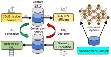
The development of hybrid sorbent/catalysts for carbon capture and conversion to chemical fuels involves several material and engineering design considerations. Herein, a metal–organic framework (MOF), known as Mg-CUK-1, is loaded with Ru and Ni nanoparticles and assessed as a hybrid material for the sequential capture and conversion of carbon dioxide (CO2) to methane (CH4). Low nanocatalyst loadings led to enhanced overall performance by preserving more CO2 uptake within the Mg-CUK-1 sorbent. Low temperature CO2 desorption from Mg-CUK-1 facilitated complete CO2 release and subsequent conversion to CH4. The influence of oxygen exposure on catalyst performance was assessed, with Ru-loaded Mg-CUK-1 exhibiting oxygen tolerance through sustained CH4 generation of 1.40 mmol g−1 over ten cycles. In contrast, Ni-loaded Mg-CUK-1 was unable to retain initial catalytic performance, reflected in an 11.4% decrease in CH4 generation over ten cycles. When combined, 0.3Ru2.7Ni Mg-CUK-1 yielded comparable overall performance to 3Ru Mg-CUK-1, indicating that Ru aids the re-reduction of NiO to Ni after O2 exposure. By combining multiple catalyst species within one hybrid sorbent/catalyst material, greater catalyst stability is achieved, resulting in sustained overall performance. The introduced strategy provides an approach for fostering resilient hydrogenation catalysts upon exposure to reactive species often found in real-world point source CO2 emissions.

1. Introduction

The Intergovernmental Panel on Climate Change's (IPCC) Sixth Assessment report highlights the need for a diverse range of carbon capture technologies to restrict rising atmospheric CO2 levels and limit outcomes associated with increasing global temperatures.1 Carbon capture and conversion to chemical fuels represents a promising mitigation strategy within a broader suite of carbon capture and utilisation (CCU) approaches. By reacting captured CO2 with green H2, the resulting fuel can act as an energy carrier easily integrated into existing supply chains for CH4 and CH3OH.2,3 The primary challenge associated with CO2 hydrogenation reactions is the significant energy requirement that needs to be overcome to deliver adequate fuel production for industrial implementation. Metal-based catalysts have been used to overcome the otherwise prohibitively large energetic barrier and are often loaded onto metal oxides to preserve nanoparticle dispersion.4

Integrating adsorption-based carbon capture into CO2 hydrogenation catalytic systems represents a recent trend in CCU research.5–7 The benefit of system integration allows for a streamlined unit with a minimized physical footprint, particularly suited for modular, distributed systems in urban areas. When co-located with point source CO2 emissions, modular CCU units can eliminate the need for CO2 transport, helping to reduce ancillary greenhouse gas emissions associated with operation.

Despite several potential advantages, there remain distinct challenges when developing integrated carbon capture and hydrogenation systems. The design of hybrid CO2 sorbent/catalyst materials is one such challenge. When cycling between carbon capture and conversion modes, reactive species have the potential to poison the included catalyst, limiting its long-term recyclability. Reduced chemical fuel yield over repeated cycles can dramatically impact overall performance with more frequent catalyst replacement leading to increased operating costs. Therefore, developing catalysts that can withstand exposure to industrially available CO2 streams comprised of O2, SOx, NOx and other reactive species needs to be addressed.

To date, hybrid sorbent/catalyst materials have focused on using metal oxides, metal carbonates and metal bicarbonates as CO2 capture agents.8–23 Once the sorbent reaches saturation through the formation of carbonate or bicarbonate species; the reactor system is heated to an appropriate reaction temperature (300–400 °C), where H2 is introduced to generate CH4. However, due to the strong carbonate/bicarbonate chemical bonds created during carbon uptake, high temperatures are necessary to completely desorb the bound CO2 so it is available for hydrogenation.24,25 Increased reaction temperatures undesirably raise the system's energy footprint while also introducing the likelihood of the reverse water–gas shift side reaction taking place.4,26 Even at high temperatures, incomplete CO2 desorption has been observed in metal oxide-based hybrid sorbent/catalyst systems.13–15,18–20,27–29

To overcome these challenges, using physisorption-based carbon capture agents in hybrid sorbent/catalysts is advantageous due to complete CO2 desorption below typical CO2 hydrogenation reaction temperatures. Metal–organic frameworks represent a class of materials demonstrating large physisorption-led CO2 uptakes.30–32 MOFs also offer significant design flexibility through careful selection of the included metal ion and organic linker components.33–36 Selecting an appropriate MOF capable of substantial CO2 adsorption capacity, robust thermal stability and structural resilience to reactive gas-phase species is central to furthering the design of hybrid sorbent/catalyst materials. MOFs have also emerged as nanocatalyst supports for CO2 hydrogenation reactions, presenting distinct mechanistic pathways from conventional metal/metal oxide systems.37,38 Understanding metal–support interactions involving MOFs remains an emerging area of investigation.

Mg-CUK-1 [Mg33-OH)2(2,4-pdc)2; 2,4-pdc = 2,4-pyridine dicarboxylate] is a thermally stable MOF that has previously been investigated as a CO2 physisorbent.39 Enhanced CO2 uptake by Mg-CUK-1 has been observed in the presence of moisture, with improvement from 4.6 wt% to 8.6 wt% at 20% relative humidity.40 H2O and CO2 commonly compete for the same adsorption sites in MOFs, hindering their implementation in real-world adsorption scenarios. Given that H2O is generated during CO2 hydrogenation reactions, sorbent stability under hydrothermal conditions is an important design consideration. Hydroxyl groups that line the Mg-CUK-1 interior have been deemed responsible for improved CO2 uptake and offering protection of the linker-node coordination bonds from framework decomposition.41 The chemical stability of Mg-CUK-1 has also been demonstrated through sustained adsorption/desorption cycling of H2S and H2O vapour, with no impact on framework crystallinity or uptake. The combination of hydrothermal stability and suitable CO2 physisorption renders Mg-CUK-1 an ideal sorbent for combined carbon capture and conversion of CO2 to chemical fuels.

Several metals, including Ni, Co, Ru, Rh, Pd and Pt, have been investigated as CO2 hydrogenation catalysts.42–45 Ni is known to be CH4 selective and offers competitive activity with platinum group metals (PGM) candidates.17,27,46 Transition metals such as Ni also benefit from being more abundant and, therefore more cost-effective than PGMs such as Ru. However, transition metals require higher temperatures to undergo reduction once oxidised.47 When considering applications where oxygen exposure is unavoidable, such as CO2 capture from point source emissions, design strategies that improve the oxygen tolerance of Ni are important for maintaining overall system performance.

In this work, Ni and Ru species are loaded into Mg-CUK-1 and the resulting hybrid sorbent/nanocatalyst is appraised for the capture and conversion of CO2 into CH4. The impact of catalyst loading and composition on CO2 uptake and CH4 generation is examined separately before being combined into a single reactor unit. The effect of CO2 stream composition on overall system performance is ascertained, culminating in the evaluation of a dual metal RuNi-loaded Mg-CUK-1 to aid with oxygen tolerance upon exposure to air during carbon capture. By offering insights into the design challenges associated with hybrid sorbent/catalyst materials, we highlight the potential for nanoparticle/MOF composites to maximize overall carbon capture and conversion system performance through judicious material design.

2. Experimental

2.1 Preparation of Mg-CUK-1

The synthesis of Mg-CUK-1 was conducted using a method reported previously.39 A solution of 2,4-pyridine dicarboxylic acid monohydrate (1 mmol, 185 mg) and potassium hydroxide (3 mL, 224 mg) was added to an aqueous solution (3 mL) of magnesium nitrate hexahydrate (1.5 mmol). Once mixed, the reaction solution was transferred into a Teflon-lined autoclave and heated to 200 °C for 15 h. The vessel was allowed to cool slowly over a six-hour timeframe. The resulting crystalline solids were separated through sonication, whereby the cloudy supernatant was drawn off and replenished with deionised H2O. The solid product was washed three times before being dried in an oven at 100 °C.

2.2 Preparation of Ni- and Ru-loaded Mg-CUK-1

Mg-CUK-1 was loaded with Ni and Ru using a double solvent impregnation approach to promote nanoparticle growth within the hydrophilic MOF interior. Before loading, Mg-CUK-1 was dried under vacuum at 150 °C for 12 h to remove any pre-adsorbed species. A 100 mg of anhydrous Mg-CUK-1 was then suspended in 5 mL of hexane. Next, 22 μL of RuCl3 or NiCl2 was added to the hexane/Mg-CUK-1 mixture and allowed to stir overnight to ensure precursor impregnation. A precursor solution of 0.15 mg mL−1 was used to produce three wt% Ru and Ni-loaded samples, while 0.30 mg mL−1 was used for the higher loading of 6 wt% Ni and 7 wt% Ru. Corresponding samples are denoted as 3Ru, 3Ni, 6Ni and 7Ru, respectively. A mixed-metal RuNi-loaded Mg-CUK-1 sample was also synthesised with precursor solution concentrations of 0.015 mg mL−1 and 0.285 mg mL−1 of Ru and Ni precursor, respectively. Again, 22 μL of precursor solution is added to 100 mg of anhydrous Mg-CUK-1 with the resulting material denoted as 0.3Ru2.7Ni. Once complete, the hexane supernatant was carefully removed, and the samples were initially dried at 80 °C before being transferred to the reactor and pre-treated at 350 °C for 12 h under a reducing atmosphere (30 mL min−1 H2).

2.3 X-ray diffraction

X-ray diffraction measurements were performed using a PANalytical Xpert Multipurpose X-ray Diffraction System (MPD) operating at 45 kV and 40 mA using a Cu Kα radiation source (λ = 1.5406 Å). Diffractograms were collected over the 5–90° 2θ range. Diffraction patterns were analyzed and processed using Highscore Plus software.

2.4 CO2 adsorption isotherms

CO2 adsorption isotherms were collected using a Micromeritics TriStar II PLUS instrument at 0 °C. Samples were thermally treated at 150 °C under vacuum (<0.015 kPa) using a Micromeritics Smart VacPrep unit to remove any residual solvent before measurement.

2.5 Transmission electron microscopy

Transmission electron microscopy (TEM) imaging was performed using a JEOL 1400 instrument at 100 kV and 55 μA. High-resolution TEM was completed using a FEI Tecnai G2 20 instrument operating at 200 kV. Before imaging, samples were dispersed in methanol and drop cast onto carbon grids.

2.6 Steady-state CO2 hydrogenation performance tests

Catalytic performance tests were conducted using 50 mg of sample loaded into a 30 mm long, 6 mm internal diameter quartz tube reactor. Each catalyst was pre-treated at 350 °C under a reducing atmosphere (30 mL min−1 H2) before performance testing.

Steady-state performance tests were conducted using a feed gas mixture of 50 mL min−1 N2, 6 mL min−1 CO2 and 24 mL min−1 H2. The total flow rate of 80 mL min−1 corresponds to a gas hourly space velocity of 48 L h−1 gcat−1. A temperature controller was used to heat the reactor from 250 °C to 400 °C at a rate of 5 °C min−1 while holding for 30 min at each 50 °C interval.

The gases leaving the reactor were sampled and analysed by two gas chromatographs; a Shimadzu 8A equipped with a thermal conductivity detector (TCD) and Zeolite 13X column for N2 and H2 detection and a Shimadzu 2010 fitted with a methanizer and flame ionization detector array and HP/PlotQ column for CH4, CO2 and CO detection. The resulting peak areas were translated to flow rates using calibration data. The data was subsequently used to calculate CO2 conversion and CH4 selectivity.

2.7 Batch CO2 capture and conversion performance tests

CO2 capture and conversion performance tests were conducted in the same reactor set up as the steady state experiments. Initially, 20 mL min−1 CO2 was passed over the hybrid sorbent/catalyst for 60 min to achieve CO2 saturation. The system was then flushed with H2 (30 mL min−1) for 20 min to ensure the only remaining CO2 in the system was held on the sorbent surface. The system was then switched to recirculation mode whereby the contents of the reactor were cycled repeatedly over the catalyst bed at 50 mL min−1. The reactor was then heated to 300 °C at 20 °C min−1 and held for 10 minutes to allow for methanation to occur. Reactor sampling proceeded for 50 minutes, whereby gas samples were redirected to the gas chromatographs for CO2 and CH4 quantification.

A reduced CO2 flow composition was also incorporated into the batch performance tests, comprising 15% CO2 (7.5 mL min−1) and the balance air (42.5 mL min−1) to simulate a dry flue gas stream. Once the CO2 adsorption and conversion stages were complete, the reactor system was cooled to 25 °C and the adsorption-reaction cycle was repeated.

2.8 X-ray photoelectron spectroscopy

X-ray photoelectron spectroscopy (XPS) was conducted using a Thermo-Fischer ESCALAB250i high-resolution X-ray photoelectron spectrometer equipped with a monochromatic Al Kα soft X-ray source (1486.6 eV). Survey spectra were collected up to 1350 eV binding energy with binding energy values referenced to the C 1s peak at 284.8 eV. Data analysis was conducted using CasaXPS.

3. Results and discussion

3.1 Hybrid sorbent/catalyst preparation

The sorbent, Mg-CUK-1, was loaded with Ru and Ni using a double-solvent impregnation strategy to promote the formation of nanoparticles within the MOF particle interior. Low catalyst loadings were selected to preserve as much of the accessible surface area of the sorbent as possible. Inductively Coupled Plasma Optical Emission Spectroscopy (ICP-OES) results reported catalyst loadings of 3.1 wt% and 6.22 wt% for 3Ni and 6Ni, respectively, and 3.41 wt% and 7.40 wt% for 3Ru and 7Ru, respectively (Table S1).

Powder X-ray diffraction patterns of Mg-CUK-1 (Fig. 1) reveal successful MOF self-assembly with peaks closely matching the simulated pattern for Mg-CUK-1 (Fig. S1). Once loaded, no peaks associated with Ru or Ni species are observed within the diffraction data, likely due to low catalyst loadings. Importantly, the diffraction peaks associated with Mg-CUK-1 are retained after pre-treatment at 350 °C, indicating that the framework is stable at temperatures necessary for CO2 hydrogenation.


image file: d2nr03338k-f1.tif
Fig. 1 X-ray diffraction patterns of Mg-CUK-1, Ni-loaded Mg-CUK-1 and Ru-loaded Mg-CUK-1.

3.2 Carbon capture sorbent performance

The influence of catalyst loading on CO2 adsorption capacity is important when formulating hybrid sorbent/catalyst materials. The pristine Mg-CUK-1 possesses the highest CO2 uptake of 5.28 mmol g−1 at 104.9 kPa and 0 °C (Fig. 2). For 3Ni and 3Ru, CO2 adsorption decreases moderately to 4.41 and 4.11 mmol g−1, respectively. The reduction in CO2 capacity can be attributed to the mass contribution of the metal catalysts and partial pore blockage arising from nanoparticle inclusion. The effect is more pronounced for larger catalyst loadings, with 6Ni and 7Ru possessing a CO2 uptake of 4.07 mmol g−1 and 3.76 mmol g−1. The slightly lower uptake for materials containing Ru is attributed to the marginally higher loadings reflected in the ICP-OES results (Table S1).
image file: d2nr03338k-f2.tif
Fig. 2 CO2 adsorption isotherms of Mg-CUK-1, Ni-loaded Mg-CUK-1 and Ru-loaded Mg-CUK-1 conducted at 0 °C.

N2 adsorption/desorption isotherms depict a similar trend in accessible surface area to the CO2 uptake profiles (Fig. S2). Mg-CUK-1 possessed the largest specific surface area of 542.3 ± 4.4 m2 g−1. 3Ni- and 3Ru-loaded Mg-CUK-1 registered a decrease in surface area to 389.7 ± 4.1 m2 g−1 and 386.7 ± 7.5 m2 g−1, respectively. Once the catalyst loading was increased further, the specific surface area again diminished to 365.9 ± 3.8 for 6Ni and 360.1 ± 7.0 for 7Ru. The slightly lower accessible surface area for Ru-loaded Mg-CUK-1 is attributed to the marginally higher catalyst loadings than Ni (Table S1).

From the CO2 adsorption experiments, it's apparent that catalyst loading impacts CO2 uptake. Increased catalyst loadings result in a decrease in both specific surface area and CO2 adsorption capacity. Therefore, when considering combined carbon capture and utilisation hybrid sorbent/catalysts, minimizing the catalyst loading is preferential from a carbon capture point of view, so long as the catalytic activity is sufficient to convert all the captured CO2. The following section will assess the performance of each material for CO2 hydrogenation.

3.3 CO2 hydrogenation catalyst performance

The CO2 hydrogenation performance of catalyst-loaded Mg-CUK-1 was assessed across a series (250–400 °C) of reaction temperatures under a steady-state stoichiometric flow of H2 and CO2 (4[thin space (1/6-em)]:[thin space (1/6-em)]1) (Fig. 3, Table S2). CO2 conversion was detected from 250 °C for all catalysts (6Ni, 3Ru and 7Ru) except 3Ni, which registered catalytic activity beyond 300 °C. An increase in CO2 conversion was observed for all catalysts with increasing temperature. Ru-loaded materials outperformed Ni at comparable loadings throughout the observed temperature range. Similarly, higher loadings led to improved CO2 conversion for both Ru and Ni. No catalytic activity was observed for samples containing only Mg-CUK-1, highlighting the importance of the Ru and Ni nanocatalysts in facilitating CO2 conversion.
image file: d2nr03338k-f3.tif
Fig. 3 Steady state CO2 methanation performance results spanning a temperature range of 250–400 °C. A continuous reactant (H2[thin space (1/6-em)]:[thin space (1/6-em)]CH4) stoichiometric molar ratio of 4[thin space (1/6-em)]:[thin space (1/6-em)]1 and gas hourly space velocity of 48 L gcat−1 h−1 were used.

All catalysts demonstrate selectivity for CH4 over CO, ranging between 71.8 ± 2.0% and 88.9 ± 1.1%. Ru-Mg-CUK-1 offered the highest CH4 selectivity at 350 °C, reaching 86.4 ± 2.8% and 89.3 ± 2.6% for 3Ru and 7Ru, respectively. Ni-loaded Mg-CUK-1 registered a maximum CH4 selectivity at 300 °C, recording 87.5 ± 1.3% and 88.5 ± 1.5% for 3Ni and 6Ni, respectively.

The largest disparity in catalyst activity occurred at 400 °C, where 3Ru and 7Ru reached CO2 conversions of 46.0 ± 2.4% and 52.5 ± 2.8%, respectively. Conversely, 3Ni and 6Ni reached a maximum CO2 conversion of 13.1 ± 1.2% and 23.3 ± 1.3%, respectively.

To understand variations in catalytic performance between each hybrid sorbent/catalyst, transmission electron microscopy was conducted to provide insights into nanoparticle dispersion and morphology (Fig. 4). Ni-loaded Mg-CUK-1 revealed a broader size distribution of nanoparticles than Ru at both catalyst loadings. Lower particle dispersion is also evident, with regions of significant nanoparticle formation and regions completely absent of nanoparticles. Conversely, Ru-loaded Mg-CUK-1 appeared highly dispersed throughout the MOF crystals, even at the higher loading of 7 wt% Ru. Greater dispersion and narrower particle size distribution is likely a significant factor in the elevated catalytic performance of the Ru-loaded Mg-CUK-1 materials. The greater Ru dispersion may be due to the higher catalyst precursor solubility of RuCl3·xH2O compared to NiCl2 used during double solvent impregnation, allowing for greater transport within the hydrophilic MOF pores. X-ray diffraction of the spent Ni- and Ru-loaded Mg-CUK-1 highlight the retention of MOF crystallinity (Fig. S3).


image file: d2nr03338k-f4.tif
Fig. 4 Transmission electron micrographs of (a) 3Ni, (b) 6Ni, (c) 3Ru and (d) 7Ru-loaded Mg-CUK-1 indicating variations in nanoparticle dispersion and morphology.

Based solely on the CO2 hydrogenation performance results, Ru-loaded Mg-CUK-1 represents the superior catalyst with consistently higher CO2 conversion and comparable CH4 selectivity when evaluated against the Ni-loaded Mg-CUK-1. Higher loadings are also preferred, providing additional active sites to facilitate CO2 hydrogenation.

However, the disparity in performance between catalysts is less pronounced when considering lower reaction temperatures. At 300 °C, 3Ru and 7Ru reach a CO2 conversion of 8.4 ± 0.9% and 14.1 ± 1.2%, respectively. 3Ni and 6Ni register a CO2 conversion of 3.7 ± 1.1% and 6.4 ± 1.0%, respectively. Given the strong contrast in operating conditions for steady-state CO2 hydrogenation and a batch-mode temperature swing CO2 capture and conversion scenario, where the reactor is repeatedly heated up to reaction temperature and cooled again to facilitate CO2 adsorption, it is worthwhile assessing each hybrid sorbent/catalyst under relevant conditions before making a judgement on which material is best suited for a combined CO2 capture and conversion system.

3.4 Influence of CO2 stream composition on overall system performance

A series of temperature-swing batch mode performance tests were conducted to assess each material as a hybrid sorbent/catalyst for CO2 capture and conversion (Fig. 5). CO2 adsorption was performed first at 25 °C allowing the sorbent to reach saturation over 60 min before raising the system to reaction temperature. The captured CO2 was then desorbed and recirculated with H2 for 20 min to enable the reaction. A reaction temperature of 300 °C was selected to minimise the system's energy footprint while offering a reasonable CO2 conversion rate. A representative raw gas chromatograph–flame ionization detector signal for the hybrid sorbent/catalyst CO2 capture and conversion experiments can be found in the ESI (Fig. S4).
image file: d2nr03338k-f5.tif
Fig. 5 CO2 capture and conversion batch recirculation results. Orange and blue columns denote CO2 desorbed and CH4 generated, respectively. Solid and transparent columns denote 100% and 15% CO2 stream composition during CO2 adsorption at 25 °C.

A stream containing 100% CO2 was first examined during the CO2 capture operation to maximise the quantity adsorbed. The amount of CO2 desorbed was inversely correlated to catalyst loading, with 3 Ni and 3Ru desorbing 3.48 and 3.51 mmol g−1 while higher loadings of 6Ni and 7Ru desorbed 3.30 and 3.31 mmol CO2 g−1, respectively. These results corroborate what was observed in the CO2 adsorption isotherms, where lower loadings afforded larger CO2 uptakes (Fig. 2).

The same CO2 adsorption/desorption trend was observed when the feed CO2 stream concentration was reduced. A feed concentration of 15% CO2/N2 was selected to emulate a typical post-combustion dry flue gas from a coal-fired or natural gas-fired power plant.48 Again, 3Ni and 3Ru registered specific CO2 desorption quantities of 1.39 and 1.40 mmol g−1, respectively. The larger catalyst loadings of 6Ni and 7Ru resulted in slightly lower CO2 desorption quantities of 1.31 and 1.32 mmol g−1, respectively. All CO2 desorption amounts for the 15% CO2 feed are lower than observed for the 100% CO2 feed stream. The effect is characteristic of adsorption-based CO2 capture, where lower CO2 partial pressures result in lower uptakes.30 This is also reflected in the CO2 adsorption isotherms for each material (Fig. 2).

From a reaction perspective, the amount of CO2 desorbed closely matched the quantity of CH4 generated for all materials. This indicates that all the CO2 initially adsorbed was able to be desorbed under reaction conditions. Furthermore, each hybrid sorbent/catalyst possessed sufficient catalyst loading to facilitate the complete conversion to methane. No CO was observed in these batch recirculation experiments, which is distinct from what was seen in the steady state CO2 hydrogenation performance tests. The difference in performance can be attributed to the longer effective residence time for the reaction to occur during batch recirculation and the excess of H2 present compared with the stoichiometric ratio (4[thin space (1/6-em)]:[thin space (1/6-em)]1) used under continuous CO2:H2 flow. Complete conversion to CH4 is advantageous in real-world settings, reducing the need for further downstream gas separations before transport and end-use.

The batch performance results offer insights into key features when designing hybrid sorbent/catalyst materials. CO2 capture, particularly from dilute CO2 streams, represents the rate-determining step of the overall process. In the system discussed here, 60 min of 15% CO2 flow was required to reach sorbent saturation, while complete conversion to CH4 took less than 20 min. Once the system was switched to recirculation, the quantity of CH4 generated was constrained by the amount of CO2 captured by the sorbent initially. Therefore, maximising the CO2 adsorption capacity of the included sorbent while minimizing the amount of catalyst represents a critical hybrid material design consideration. Minimizing catalyst loading allows for the maximum CO2 adsorption capacity within the selected sorbent. However, maintaining enough catalyst to facilitate the complete conversion of captured CO2 is required. In this case, 3Ni and 3Ru provide enough activity to convert all the CO2 captured initially by the Mg-CUK-1 sorbent. Higher loadings (6Ni and 7Ru) decrease overall system performance caused by diminished CO2 uptake.

3.5 Effect of oxygen exposure on recycled catalyst performance

Another important consideration in designing hybrid sorbent/catalysts is the resilience of the included catalyst towards oxygen exposure. Oxygen is present in CO2-rich point source emissions arising from fossil fuel power generation, cement production and ethanol fermentation as well as direct air capture scenarios.

To assess catalyst oxygen tolerance, 3 wt% Ni and 3 wt% Ru underwent ten repeated CO2 capture and conversion batch performance tests (Fig. 6). The hybrid sorbent/catalyst was exposed to a 15% CO2 in an 85% air stream throughout the carbon capture operating mode. 3Ru maintained CH4 generation between 1.39 and 1.41 mmol g−1 over the ten cycles, demonstrating resilience towards oxygen exposure. In contrast, 3Ni registered an 11.4% decrease in CH4 generation from an initial value of 1.40 mmol g−1 to 1.24 mmol g−1 after ten cycles. The reduction in CH4 generated resulted from incomplete CO2 conversion, with unreacted CO2 observed in the gas chromatographs.


image file: d2nr03338k-f6.tif
Fig. 6 Influence of the included metal nanoparticle on catalyst performance upon exposure to air during CO2 capture.

To improve the oxygen tolerance of 3Ni, a RuNi mixed metal catalyst was loaded onto Mg-CUK-1. The resulting hybrid 0.3Ru2.7Ni sorbent/catalyst contained 0.34 wt% Ru and 2.73 wt% Ni (Table S1). XRD and CO2 adsorption isotherms can be found in the ESI (Fig. S5–S6). Upon exposure to ten repeated capture and conversion performance tests, 0.3Ru2.7Ni maintained a CH4 generation of between 1.40 and 1.37 mmol g−1.

To understand the retained performance observed in 0.3Ru2.7Ni, XPS was conducted on each material before and after the oxygen-tolerance performance tests (Fig. S7–S8). Before catalytic performance testing, both 3Ni and 0.3Ru2.7Ni contained spin–orbit splitting peaks within the Ni 2p region at binding energies of 872.51 eV (2p1/2) and 853.48.33 eV (2p3/2), indicating Ni2+ reduction to Ni0 (Fig. 7). After ten reaction cycles, peaks associated with Ni0 were not observable in the spent 3Ni, while more Ni0 was retained within 0.3Ru2.7Ni. The XPS observations suggest that Ni oxidation was responsible for diminished catalyst performance within 3Ni, while 0.3Ru2.7Ni retained more active Ni0 species to facilitate CO2 hydrogenation. A persistent set of spin–orbit splitting peaks at binding energies of 873.64 eV (2p1/2) and 855.50 eV (2p3/2) were evident throughout all samples, indicating a degree of oxidation (as NiO or Ni(OH)2) present, likely due to atmospheric exposure during handling before measurement.


image file: d2nr03338k-f7.tif
Fig. 7 High-resolution X-ray photoelectron spectroscopy of 3Ni, and 0.3Ru2.7Ni before and after 10 carbon capture and conversion performance tests.

While quantification of the Ni2+ to Ni0 ratio is challenging given the complexity of Ni 2p XPS spectra, it is possible to qualitatively compare Ni 2p3/2 peaks to assess the extent of Ni reduction maintained after performance testing (Tables S3–S5).49 The deconvoluted peaks at ∼853 eV and ∼855 eV offer an approximation to the relative quantities of surface Ni0 and Ni2+ present within each sample. Before cyclic performance testing, 3Ni and 0.3Ru2.7Ni possessed similar degrees of oxidation corresponding to 27.1% and 28.1% Ni0 relative to Ni2+. After oxygen tolerance performance testing, 3Ni relinquished the peak corresponding to Ni0, indicating complete Ni oxidation, while 0.3Ru2.7Ni retained 23.6% Ni0 relative to Ni2+. These semi-quantitative results highlight that the presence of Ru within a Ni-dominant hybrid sorbent-catalyst coincided with greater retention of active Ni0 species after repeated oxygen exposure.

XPS regions corresponding to Ru were also analyzed to gain similar insights found for Ni. Unfortunately, the strong overlap in Ru 3d and C 1s peaks made it difficult to assess the degree of Ru oxidation in 3Ru and 0.3Ru2.7Ni (Fig. S9).50 Ru peak intensities were dwarfed by the much higher concentration of C present within the 2,4-pyridine dicarboxylate organic linker of Mg-CUK-1. Nevertheless, Ru 3d peaks were observed for the neat 3Ru at binding energies of 281.06 eV and 282.49 eV, likely corresponding to RuO2 species. After oxygen tolerance performance testing, a shift to lower binding energies (280.97 eV and 282.37 eV) indicated a decrease in the Ru oxidation state. Complementary peaks for Ru 3p were also observed for 3Ru; however, the low Ru loading of 0.3Ru2.7Ni precluded any observable peak within the Ru 3p region (Fig. S10). A Ru3p3/2 peak shift from 463.20 eV (3Ru Neat) to 462.90 eV (3Ru Spent) indicated a decrease in Ru oxidation state towards active Ru0 species after oxygen tolerance performance testing. The retention of Ru0 species appears pivotal to the enduring catalytic performance of 3Ru Mg-CUK-1 despite oxygen exposure during CO2 capture.

The Mg coordination environment within Mg-CUK-1 changed upon catalyst loading and performance testing. A dominant peak centered at 49.71 eV within the Mg 2p region was observed for neat Mg-CUK-1 (Fig. S11). After catalyst loading, the peak center shifted to 50.45 eV, 50.65 eV and 50.46 eV for 3Ni, 3Ru and 0.3Ru2.7Ni, respectively. The spent samples containing Ru indicated a reversion in binding energy back towards the neat Mg-CUK-1, with peaks centered at 50.50 eV and 50.35 eV for 3Ru and 0.3Ru2.7Ni, respectively. The subtle shift to lower binding energies alludes to a shift in electron density from Mg-O coordination bonds present within Mg-CUK-1 towards Mg-OH moieties lining the MOF interior.51 3Ni continued to shift the Mg 2p peak to higher binding energy (50.53 eV) after performance testing. The varied trend in the Mg coordination environment may be caused by the difference in redox properties between Ru and Ni.

The O 1s region for Mg-CUK-1 revealed a dominant peak centered at 531.64 eV with lower intensity peaks on either side at 529.47 eV and 533.33 eV (Fig. S12). Upon catalyst loading, the peak centered at 531 eV became dominant, likely due to the inclusion of Ru–O and Ni–O surface species. The spent materials retained a similar oxygen coordination environment to the Ni- and Ru-loaded Mg-CUK-1. Given the large variety of oxygen bonding in both Mg-CUK-1 and the oxidized catalysts, it is difficult to glean much insight from the O 1s region.

The N 1s region reveals that the nitrogen in 2,4-pyridine dicarboxylate was retained upon catalyst loading and performance testing (Fig. S13). Given that the Mg–N coordination bond represents the weakest junction within Mg-CUK-1, the persistent nitrogen coordination environment is a testament to the stability of the Mg-MOF under harsh reaction conditions. Similarly, C 1s peaks associated with Mg-CUK-1 remain consistent throughout catalyst loading and performance testing (Fig. S9). Graphitic carbon generation associated with MOF decomposition previously seen with Mg-MOF-74 is not observed for Mg-CUK-1.38 Catalyst dispersion (Fig. S14) appears similar in 0.3Ru2.7Ni to what was observed in Fig. 4.

Several studies involving Ni-based hybrid sorbent/catalysts have been conducted previously; however, they primarily involve O2-free CO2 streams.11,52–54 The surface passivation of Ni active sites has been observed elsewhere, indicating its lack of suitability for hybrid sorbent/catalyst systems involving exposure to O2.28

Conversely, Ru possesses distinctive redox properties that allow for rapid reduction after exposure to O2.12,27 PGMs, such as Ru, are known to dissociate H2, providing a strong reducing agent (H radicals) to lower the reduction temperature required for NiO.55 Therefore, by introducing small quantities of Ru into a predominantly Ni-based catalyst, the hybrid sorbent/catalyst's overall performance can be sustained without relying solely on PGMs. The economic implications of utilising Ru-based catalysts at scale are worth considering. As of May 2022, Ru ($US22.7 per g) was almost three orders of magnitude more expensive than Ni ($US 0.03 per g). If Ni can replace a significant portion of the Ru used within a hybrid sorbent/catalyst, this can translate to a significant operating cost reduction when considering carbon capture and conversion industrial implementation. Ru-promoted Ni nanocatalysts can facilitate the re-reduction of surface NiO species such that both Ni and Ru sites remain active for CO2 hydrogenation.56 However, using low loadings of Ru (0.5%Ru) in the absence of Ni has led to diminished performance upon cycling, attributed to deactivation and potentially sintering upon exposure to O2 and steam in flue gas.20

3.6 Comparison of hybrid sorbent/catalyst performance with previously reported dual functional materials

The overall hybrid sorbent/catalyst performance of 0.3Ru2.7Ni Mg-CUK- is closely associated with the CO2 adsorption behaviour exhibited by Mg-CUK-1. A promising CO2 adsorption capacity (1.4 mmol g−1 with 15% CO2/air flow) relative to most of the previously reported metal oxide/carbonate-based DFMs provides a platform for enhanced CH4 generation. A summary of previously reported DFM performance data for the capture and conversion of CO2 to CH4 can be found in the ESI (Fig. S15 and Table S6). Most experimental studies in the literature involving DFMs utilize an isothermal reactor configuration, different to the temperature-swing reactor operating conditions used in this work. The key experimental conditions associated with each previously reported study used for comparison are tabulated in Table S6.

Weak-to-moderate CO2 interactions within Mg-CUK-1 allow for complete CO2 desorption well below hydrogenation reaction temperature. Consequently, all the CO2 captured originally is released and available for CH4 generation. Complete CO2 release is not always a feature of hybrid sorbent/catalysts using metal oxides.24 Upon forming carbonate or bicarbonate species, the temperatures required for complete chemical sorbent regeneration may exceed the required hydrogenation reaction temperature. This is most notable for DFMs reliant on CaO or MgO for CO2 uptake. If a low reaction temperature (such as 300 °C) is selected, incomplete CO2 desorption is likely, resulting in a reduced sorbent working capacity. The work presented here allows for complete CO2 desorption and conversion to CH4 at 300 °C.

Utilising solid adsorbents with large CO2 uptakes and low regeneration temperatures is central to designing hybrid sorbent/catalysts for combined CO2 capture and conversion applications. Highly dispersed nanocatalysts at low loadings allow for greater preservation of CO2 adsorption capacity. The chosen catalyst needs to be able to withstand exposure to reactive species such as oxygen that are often present in CO2-rich point source emissions. In this work, Ni-based catalysts were unable to retain their performance after oxygen exposure. However, once combined with a small loading of Ru (0.34 wt%), the Ni species retained their catalytic activity. Future work will assess the feasibility of applying hybrid sorbent/catalysts to direct air CO2 capture and conversion to chemical fuels. Further material design and engineering optimisation will also be conducted to tailor the system to more challenging CO2 capture streams that include other reactive species such as H2O, NOx and SO2.

4 Conclusions

The advancement of hybrid sorbent/catalysts for the combined capture and conversion of CO2 to CH4 requires an understanding into how both the selected sorbent and catalyst perform under industrially relevant conditions. Sorbents capable of large CO2 adsorption capacities through weak-to-moderate interactions allow for complete CO2 utilisation at mild reaction temperatures. Mg-CUK-1 exhibits a physisorption-driven CO2 uptake of 1.40 mmol g−1 under simulated dry flue gas conditions. CO2 capture was identified as the limiting factor in overall system performance. By minimizing catalyst loading to 3 wt%, most of the CO2 uptake within Mg-CUK-1 is preserved without compromising subsequent catalytic hydrogenation to CH4.

The selected catalyst must withstand O2 exposure during CO2 capture when considering real-world point source CO2 emissions. Ru nanoparticles (3Ru Mg-CUK-1) were capable of withstanding oxygen exposure resulting in the sustained catalytic performance of 1.40 mmol CH4 g−1 over ten carbon capture and conversion cycles. In contrast, Ni nanoparticles (3Ni Mg-CUK-1) could not maintain initial catalytic performance, resulting in an 11.4% decrease in CH4 generation over ten cycles.

When a small amount of Ru was added to Ni Mg-CUK-1, the resulting hybrid sorbent/catalyst (0.3Ru2.7Ni Mg-CUK-1) retained catalytic performance despite oxygen exposure during CO2 capture. Including 0.3 wt% Ru into a predominantly Ni-based catalyst (0.3Ru2.7Ni Mg-CUK-1) enables equivalent hybrid sorbent/catalyst performance to 3Ru Mg-CUK-1. The finding helps reduce the cost of hybrid sorbent/catalyst systems without compromising overall performance. The demonstrated material design approach can be used to establish more resilient catalysts in the presence of a range of reactive species known to diminish performance.

Author contributions

TZ contributed to the conceptualization, formal analysis, investigation, methodology, visualization, and writing – original draft. KL, ZH, JS and RA assisted with the conceptualization, project administration, supervision, and writing – review & editing. JS and EL aided the methodology development. JS and RA facilitated the funding acquisition.

Conflicts of interest

The authors have no conflicts of interest to declare.

Acknowledgements

This research was supported by an Australian Government Research Training Program (RTP) Scholarship in conjunction with the Commonwealth Scientific and Industrial Research Organisation (CSIRO) and EcoMag Ltd through the inaugural industry PhD (iPhD) program. The authors acknowledge the use of the Solid State & Elemental Analysis, Spectroscopy and Electron Microscope Units within the Mark Wainwright Analytical Centre (MWAC) at UNSW Sydney.

References

  1. P. R. Shukla, J. Skea, R. Slade, A. Al Khourdajie, R. van Diemen, D. McCollum, M. Pathak, S. Some, P. Vyas, R. Fradera, M. Belkacemi, A. Hasija, G. Lisboa, S. Luz and J. Malley, Climate Change 2022: Mitigation of Climate Change. Contribution of Working Group III to the Sixth Assessment Report of the Intergovernmental Panel on Climate Change, IPCC, Cambridge University Press, Cambridge, UK and New York, NY, USA, 2022 Search PubMed.
  2. R. Daiyan, I. MacGill and R. Amal, ACS Energy Lett., 2020, 5, 3843–3847 CrossRef CAS.
  3. J. W. Maina, J. M. Pringle, J. M. Razal, S. Nunes, L. Vega, F. Gallucci and L. F. Dumée, ChemSusChem, 2021, 14, 1805–1820 CrossRef CAS PubMed.
  4. E. T. Kho, T. H. Tan, E. Lovell, R. J. Wong, J. Scott and R. Amal, Green Energy Environ., 2017, 2, 204–217 CrossRef.
  5. J. Zhang, C. D. Sewell, H. Huang and Z. Lin, Adv. Energy Mater., 2021, 11, 2102767 CrossRef CAS.
  6. I. S. Omodolor, H. O. Otor, J. A. Andonegui, B. J. Allen and A. C. Alba-Rubio, Ind. Eng. Chem. Res., 2020, 59, 17612–17631 CrossRef CAS.
  7. B. Shao, Y. Zhang, Z. Sun, J. Li, Z. Gao, Z. Xie, J. Hu and H. Liu, Green Sustainable Process Chem. Environ. Eng. Sci., 2022, 3, 189–198 Search PubMed.
  8. J. V. Veselovskaya, P. D. Parunin, O. V. Netskina, L. S. Kibis, A. I. Lysikov and A. G. Okunev, Energy, 2018, 159, 766–773 CrossRef CAS.
  9. J. V. Veselovskaya, P. D. Parunin and A. G. Okunev, Catal. Today, 2017, 298, 117–123 CrossRef CAS.
  10. J. V. Veselovskaya, P. D. Parunin, O. V. Netskina and A. G. Okunev, Top. Catal., 2018, 61, 1528–1536 CrossRef CAS.
  11. C. Miguel, M. Soria, A. Mendes and L. Madeira, Chem. Eng. J., 2017, 322, 590–602 CrossRef CAS.
  12. C. Janke, M. Duyar, M. Hoskins and R. Farrauto, Appl. Catal., B, 2014, 152, 184–191 CrossRef.
  13. M. S. Duyar, S. Wang, M. A. Arellano-Trevino and R. J. Farrauto, J. CO2 Util., 2016, 15, 65–71 CrossRef CAS.
  14. M. S. Duyar, M. A. A. Trevino and R. J. Farrauto, Appl. Catal., B, 2015, 168, 370–376 CrossRef.
  15. Q. Zheng, R. Farrauto and A. C. Nguyen, Ind. Eng. Chem. Res., 2016, 55, 6768–6776 CrossRef CAS.
  16. S. J. Park, M. P. Bukhovko and C. W. Jones, Chem. Eng. J., 2021, 420, 130369 CrossRef CAS.
  17. S. Wang, E. T. Schrunk and H. Mahajan, Catalysts, 2017, 7, 88 CrossRef.
  18. C. Jeong-Potter, M. Abdallah, C. Sanderson, M. Goldman, R. Gupta and R. Farrauto, Appl. Catal., B, 2021, 307, 120990 CrossRef.
  19. C. Jeong-Potter and R. Farrauto, Appl. Catal., B, 2021, 282, 119416 CrossRef CAS.
  20. C. Jeong-Potter, A. Porta, R. Matarrese, C. G. Visconti, L. Lietti and R. Farrauto, Appl. Catal., B, 2022, 310, 121294 CrossRef CAS.
  21. S. Cimino, F. Boccia and L. Lisi, J. CO2 Util., 2020, 37, 195–203 CrossRef CAS.
  22. S. Cimino, R. Russo and L. Lisi, Chem. Eng. J., 2022, 428, 131275 CrossRef CAS.
  23. L. Hu and A. Urakawa, J. CO2 Util., 2018, 25, 323–329 CrossRef CAS.
  24. M. T. Dunstan, F. Donat, A. H. Bork, C. P. Grey and C. R. Müller, Chem. Rev., 2021, 121, 12681–12745 CrossRef CAS PubMed.
  25. A. Porta, R. Matarrese, C. G. Visconti, L. Castoldi and L. Lietti, Ind. Eng. Chem. Res., 2021, 60, 6706–6718 CrossRef CAS.
  26. H. Wu, Y. Chang, J. Wu, J. Lin, I. Lin and C. Chen, Catal. Sci. Technol., 2015, 5, 4154–4163 RSC.
  27. S. Wang, E. T. Schrunk, H. Mahajan and R. J. Farrauto, Catalysts, 2017, 7, 88 CrossRef.
  28. M. A. Arellano-Treviño, Z. He, M. C. Libby and R. J. Farrauto, J. CO2 Util., 2019, 31, 143–151 CrossRef.
  29. M. A. Arellano-Treviño, N. Kanani, C. W. Jeong-Potter and R. J. Farrauto, Chem. Eng. J., 2019, 375, 121953 CrossRef.
  30. R. Aniruddha, I. Sreedhar and B. M. Reddy, J. CO2 Util., 2020, 42, 101297 CrossRef CAS.
  31. Z. Hu, Y. Wang, B. B. Shah and D. Zhao, Adv. Sustainable Syst., 2019, 3, 1800080 CrossRef.
  32. C. G. Piscopo and S. Loebbecke, ChemPlusChem, 2020, 85, 538 CrossRef CAS PubMed.
  33. J.-R. Li, J. Yu, W. Lu, L.-B. Sun, J. Sculley, P. B. Balbuena and H.-C. Zhou, Nat. Commun., 2013, 4, 1–8 CAS.
  34. A. M. Fracaroli, H. Furukawa, M. Suzuki, M. Dodd, S. Okajima, F. Gandara, J. A. Reimer and O. M. Yaghi, J. Am. Chem. Soc., 2014, 136, 8863–8866 CrossRef CAS PubMed.
  35. R. D'Amato, A. Donnadio, M. Carta, C. Sangregorio, D. Tiana, R. Vivani, M. Taddei and F. Costantino, ACS Sustainable Chem. Eng., 2019, 7, 394–402 CrossRef.
  36. A. Zárate, R. A. Peralta, P. A. Bayliss, R. Howie, M. Sánchez-Serratos, P. Carmona-Monroy, D. Solis-Ibarra, E. González-Zamora and I. A. Ibarra, RSC Adv., 2016, 6, 9978–9983 RSC.
  37. W. K. Fan and M. Tahir, Ind. Eng. Chem. Res., 2021, 60, 13149–13179 CrossRef CAS.
  38. T. Zurrer, K. Wong, J. Horlyck, E. C. Lovell, J. Wright, N. M. Bedford, Z. Han, K. Liang, J. Scott and R. Amal, Adv. Funct. Mater., 2021, 31, 2007624 CrossRef CAS.
  39. B. Saccoccia, A. M. Bohnsack, N. W. Waggoner, K. H. Cho, J. S. Lee, D. Y. Hong, V. M. Lynch, J. S. Chang and S. M. Humphrey, Angew. Chem., Int. Ed., 2015, 54, 5394–5398 CrossRef CAS PubMed.
  40. I. A. Ibarra, G. Maurin, S. M. Humphrey, S. Devautour-Vinot, E. González-Zamora, J. Balmaseda, M. Sagastuy-Breña, P. Mileo, E. Sánchez-González, J. Reynolds III and T. Jurado-Vazquez, Dalton Trans., 2018, 47, 15827–15834 RSC.
  41. E. Sánchez-González, P. G. M. Mileo, M. Sagastuy-Breña, J. R. Álvarez, J. E. Reynolds, A. Villarreal, A. Gutiérrez-Alejandre, J. Ramírez, J. Balmaseda, E. González-Zamora, G. Maurin, S. M. Humphrey and I. A. Ibarra, J. Mater. Chem. A, 2018, 6, 16900–16909 RSC.
  42. M. Aziz, A. Jalil, S. Triwahyono, R. Mukti, Y. Taufiq-Yap and M. Sazegar, Appl. Catal., B, 2014, 147, 359–368 CrossRef CAS.
  43. A. Karelovic and P. Ruiz, ACS Catal., 2013, 3, 2799–2812 CrossRef CAS.
  44. J. H. Kwak, L. Kovarik and J. Szanyi, ACS Catal., 2013, 3, 2449–2455 CrossRef CAS.
  45. J. H. Kwak, L. Kovarik and J. Szanyi, ACS Catal., 2013, 3, 2094–2100 CrossRef CAS.
  46. S. Carenco, C. Sassoye, M. Faustini, P. Eloy, D. P. Debecker, H. Bluhm and M. Salmeron, J. Phys. Chem. C, 2016, 120, 15354–15361 CrossRef CAS.
  47. S. Jantarang, E. C. Lovell, T. H. Tan, J. Scott and R. Amal, Prog. Nat. Sci.: Mater. Int., 2018, 28, 168–177 CrossRef CAS.
  48. A. Sayari, Y. Belmabkhout and R. Serna-Guerrero, Chem. Eng. J., 2011, 171, 760–774 CrossRef CAS.
  49. M. C. Biesinger, B. P. Payne, L. W. M. Lau, A. Gerson and R. S. C. Smart, Surf. Interface Anal., 2009, 41, 324–332 CrossRef CAS.
  50. D. J. Morgan, Surf. Interface Anal., 2015, 47, 1072–1079 CrossRef CAS.
  51. D. Tie, F. Feyerabend, N. Hort, R. Willumeit and D. Hoeche, Adv. Eng. Mater., 2010, 12, B699–B704 CrossRef.
  52. S. M. Kim, P. M. Abdala, M. Broda, D. Hosseini, C. Copéret and C. Müller, ACS Catal., 2018, 8, 2815–2823 CrossRef CAS.
  53. H. Sun, J. Wang, J. Zhao, B. Shen, J. Shi, J. Huang and C. Wu, Appl. Catal., B, 2019, 244, 63–75 CrossRef CAS.
  54. A. Al-Mamoori, A. A. Rownaghi and F. Rezaei, ACS Sustainable Chem. Eng., 2018, 6, 13551–13561 CrossRef CAS.
  55. F. Drault, C. Comminges, F. Can, L. Pirault-Roy, F. Epron and A. Le Valant, Materials, 2018, 11, 819 CrossRef PubMed.
  56. L. Proaño, M. A. Arellano-Treviño, R. J. Farrauto, M. Figueredo, C. Jeong-Potter and M. Cobo, Appl. Surf. Sci., 2020, 533, 147469 CrossRef.

Footnote

Electronic supplementary information (ESI) available. See DOI: https://doi.org/10.1039/d2nr03338k

This journal is © The Royal Society of Chemistry 2022