
 Open Access Article
 This Open Access Article is licensed under a
 Creative Commons Attribution 3.0 Unported Licence
Characterization of lipid bilayers adsorbed to functionalized air/water interfaces†
Julio
Pusterla
 a,
Ernesto
Scoppola
b,
Christian
Appel
a,
Tetiana
Mukhina
a,
Chen
Shen
c,
Gerald
Brezesinski
a and
Emanuel
Schneck
*a
a,
Ernesto
Scoppola
b,
Christian
Appel
a,
Tetiana
Mukhina
a,
Chen
Shen
c,
Gerald
Brezesinski
a and
Emanuel
Schneck
*a
aInstitute for Condensed Matter Physics, TU Darmstadt, Hochschulstrasse 8, 64289 Darmstadt, Germany. E-mail: emanuel.schneck@pkm.tu-darmstadt.de
bMax Planck Institute of Colloids and Interfaces, Am Mühlenberg 1, 14476 Potsdam, Germany
cDeutsches Elektronen-Synchrotron DESY, Notkestrasse 85, 22607 Hamburg, Germany
First published on 3rd October 2022
Abstract
Lipid bilayers immobilized in planar geometries, such as solid-supported or “floating” bilayers, have enabled detailed studies of biological membranes with numerous experimental techniques, notably X-ray and neutron reflectometry. However, the presence of a solid support also has disadvantages as it complicates the use of spectroscopic techniques as well as surface rheological measurements that would require surface deformations. Here, in order to overcome these limitations, we investigate lipid bilayers adsorbed to inherently soft and experimentally well accessible air/water interfaces that are functionalized with Langmuir monolayers of amphiphiles. The bilayers are characterized with ellipsometry, X-ray scattering, and X-ray fluorescence. Grazing-incidence X-ray diffraction reveals that lipid bilayers in a chain-ordered state can have significantly different structural features than regular Langmuir monolayers of the same composition. Our results suggest that bilayers at air/water interfaces may be well suited for fundamental studies in the field of membrane biophysics.
1. Introduction
Biological membranes are major components of all living organisms. They form the boundaries between the various compartments of cells and constitute platforms for essential biochemical processes like enzymatic reactions, molecular transport, and signal transduction.1,2 To understand the details of these processes, structural insight is often a prerequisite. Over the last several decades, various experimental techniques, notably X-ray and neutron reflectometry and scattering, have enabled the structural characterization of lipid bilayers and more complex models of biological membranes at sub-nanometer resolution.3–8 This approach has led to a considerable progress in our understanding of intramembrane molecular distributions,3,4 interactions of membranes with drugs, water soluble proteins and other components of the aqueous medium,5–7 and inter-leaflet lipid exchange dynamics.8 All of this was only possible with the simultaneous development of methods for membrane immobilization in planar geometries, such as solid-supported membranes,9,10 or membranes floating on polymers,11,12 soft tethers,13,14 or lipid bilayers.15 However, the presence of a solid support has a number of disadvantages. At first, it prevents any investigations that involve surface deformations, such as interfacial dilatational rheology16 which would yield insights into the viscoelastic and mechanical membrane properties. Moreover, the presence of condensed bulk media on both sides of the membrane (the aqueous phase and the solid) exclude or at least complicate other measurement techniques, such as infrared spectroscopy.17,18 Regarding surface X-ray diffraction for the study of crystalline ordering in lipid bilayers,19 the absence of a solid support may widen the range of applicability towards a controlled variation of the area per lipid.In the present work, we investigated lipid bilayers adsorbed to planar air/water interfaces that are functionalized with Langmuir monolayers of amphiphiles. The formation of these bilayers through the fusion of small unilamellar vesicles (SUVs) is promoted by electrostatic attraction. The interfacial layers were characterized by ellipsometry, various X-ray scattering techniques, and X-ray fluorescence which, in combination, provide a comprehensive structural picture of the surface-adsorbed bilayers. Bilayers in fluid (Lα) and in chain-ordered (Lβ) phases were studied. The Lβ phase of a lipid bilayer was characterized for the first time by grazing-incidence X-ray diffraction at the air/water interface and the chain ordering was found to be significantly different from that in a regular Langmuir monolayer of the same composition.
2. Materials and methods
2.1. Chemicals
The phospholipids 1,2-dimyristoyl-sn-glycero-3-phosphocholine (DMPC), 1,2-dimyristoyl-sn-glycero-3-phospho-1′-rac-glycerol (DMPG), 1,2-dipalmitoyl-sn-glycero-3-phosphoethanolamine (DPPE) and the cationic lipids 1,2-dimyristoyl-3-trimethylammonium-propane (DMTAP) and 1,2-stearoyl-3-trimethylammonium-propane (DSTAP) were purchased from Sigma-Aldrich (Merck KGaA, Germany). The fluorinated amphiphile 1H,1H-perfluorooctadecan-1-ol (PFOL) was purchased from Proactive Molecular Research (USA) and the perfluorooctadecanoic acid (PFOA) from Santa Cruz Biotechnology, Inc. (USA). High purity (99.5–99.9%) NaCl was purchased from Sigma-Aldrich. Hexane, methanol, and chloroform were of the highest commercial purity available and were purchased from Sigma-Aldrich (Merck KGaA, Germany).2.2. Sample preparation
The lipidic mixture of DPPE–DSTAP (70![[thin space (1/6-em)]](https://www.rsc.org/images/entities/char_2009.gif) :30 mol%) was spread onto the air/water interface from a solution of chloroform–methanol (7:3, v/v) and the mixture of PFOL–PFOA (70:30 mol%) from a solution of hexane–ethanol (9:1, v/v). Pressure-area isotherms were recorded with a KSV NIMA Langmuir trough (KSV, Finland). Multilamellar vesicles (MLVs, 70:30 mol% of DMPC–DMTAP or DMPC–DMPG) were prepared by generating a uniform lipid film on the wall of a glass test tube by solvent evaporation under an N2 stream from a lipidic solution in chloroform–methanol (7:3, v/v). Remaining traces of solvent were removed with a desiccator under vacuum for 2 hours. The dried lipids were then hydrated with water and subjected to three freezing–thawing cycles (−195 °C and 40 °C, respectively) to get MLVs. Finally, SUVs were prepared by extrusion (20 times, extruder set with holder/heating block from Avanti Polar Lipids, USA) of MLVs composed by DMPC–DMTAP or DMPC–DMPG through polycarbonate filters with 50 nm pore size, at room temperature.
:30 mol%) was spread onto the air/water interface from a solution of chloroform–methanol (7:3, v/v) and the mixture of PFOL–PFOA (70:30 mol%) from a solution of hexane–ethanol (9:1, v/v). Pressure-area isotherms were recorded with a KSV NIMA Langmuir trough (KSV, Finland). Multilamellar vesicles (MLVs, 70:30 mol% of DMPC–DMTAP or DMPC–DMPG) were prepared by generating a uniform lipid film on the wall of a glass test tube by solvent evaporation under an N2 stream from a lipidic solution in chloroform–methanol (7:3, v/v). Remaining traces of solvent were removed with a desiccator under vacuum for 2 hours. The dried lipids were then hydrated with water and subjected to three freezing–thawing cycles (−195 °C and 40 °C, respectively) to get MLVs. Finally, SUVs were prepared by extrusion (20 times, extruder set with holder/heating block from Avanti Polar Lipids, USA) of MLVs composed by DMPC–DMTAP or DMPC–DMPG through polycarbonate filters with 50 nm pore size, at room temperature.
2.3. Ellipsometry
A null ellipsometer (Multiskop, Optrel GbR, Germany) with a He–Ne laser (λ = 632.8 nm) was used to monitor lipid layer thicknesses at the air/water interface. The incident angle was set to 57°. The DPPE–DSTAP monolayer was analyzed at a surface pressure of π = 30 mN m−1 using a home-made Teflon trough of dimensions 70 mm × 70 mm × 4 mm covered by a lid to prevent evaporation. The DMPC–DMPG SUVs were injected with a syringe directly into the subphase through a thin side channel. The ratio of the complex reflection coefficients for p-polarized and s-polarized light, rp and rs, can be described by the two ellipsometric angles Ψ and Δ:20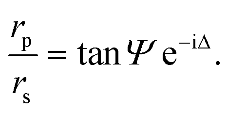 | (1) |
These two angles depend on the refractive indices of the two bulk media and the refractive index and thickness of the lipid film. Within the framework of a specific layer model (software Elli70 by Optrel) and with fixed refractive indices for all components, the lipid layer thickness can thus be reconstructed from the measurements.21
2.4. X-ray reflectometry (XRR)
XRR measurements were performed using a D8 Advance reflectometer (Bruker AXS, Karlsruhe, Germany) featuring a vertical goniometer and horizontal sample geometry, allowing the liquid surface to be studied without being disturbed during the measurements. A Langmuir trough (KSV 1000, Helsinki, Finland) with one Teflon barrier for asymmetric film compression was enclosed in a box with Kapton windows through which the incident and reflected X-ray beams pass. The dimensions of the trough were 85 mm × 320 mm × 4 mm for a total subphase volume of ≈110 mL when filled to a positive meniscus.Reflectivity curves were measured in the θ–2θ geometry, where θ is the incident angle. A conventional X-ray tube with a Cu anode (Cu Kα, wavelength λ = 1.54 Å) was used to generate an X-ray beam with a line focus. The beam was monochromized by a Göbel mirror (W/Si multilayer mirror) and collimated through two narrow horizontal slits of 0.1 mm with a switchable absorber (calibrated Cu attenuator) in between. Soller slits (Δθx = 25 mrad) were placed after the last horizontal slit and directly in front of the detector. The intensity was recorded with a Våntec-1 line detector (Bruker AXS, Germany). Data were corrected using the known attenuation factors. Finally, the angular reflectivity scans were transformed to reflectivity curves as a function of the perpendicular scattering vector component, Qz = 4πsinθ/λ.22 For analysis, the experimental data were compared with theoretically modeled XRR curves based on a slab-model representation of the electron density profiles of the interfacial lipid layers. These profiles were discretized into 1 Å-thin sub-slabs of constant electron density, and the corresponding Qz-dependent reflectivities, R(Qz), were then calculated from the Fresnel reflection laws at each slab-slab interface using the iterative recipe of Parratt.23 Finally, all model parameters (electron densities, layer thicknesses, and roughness) were varied until the best agreement with the experimental data was reached via χ2 minimization.
2.5. Grazing-incidence X-ray scattering techniques
Grazing-incidence X-ray scattering experiments (GIXOS, GIXD, and TRXF, see below) were carried out at the beamline P08 at storage ring PETRA III of Deutsches Elektronen-Synchrotron (DESY, Hamburg, Germany). The Langmuir trough (Riegler & Kirstein, Potsdam, Germany) was located in a hermetically sealed container with Kapton windows, and the temperature was kept at 27 °C by a thermostat. The container was constantly flushed with a stream of humidified helium (He) to prevent air scattering and the generation of reactive oxygen species. The synchrotron X-ray beam was monochromatized to a photon energy of 15 keV, corresponding to a wavelength of λ = 0.827 Å. The incident angle was adjusted to θi = 0.07°, slightly below the critical angle of total reflection, θc = 0.082°. A ground glass plate was placed approximately 0.3 – 1 mm beneath the illuminated area of the monolayer in order to reduce mechanically excited surface waves.Under total-reflection conditions, an X-ray standing wave (SW) is formed at the air/water interface. The penetration depth Λ of its evanescent tail into the aqueous hemispace is a function of the angle of incidence θi:24
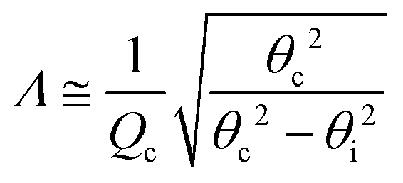 | (2) |
sinθc/λ is the momentum transfer at the critical angle, such that Λ ≈ 8 nm. The exact shape Φ(z) of the SW intensity along the vertical position z for a given incident angle follows from the interfacial electron density profile ρ(z) and can be computed via the phase-correct summation of all reflected and transmitted partial waves occurring at the density gradients, as has been described previously.25,26 For lipid layers immobilized at the air/water interface, the profile ρ(z) can be described conveniently with a slab model,27 where the parameters of individual slabs in terms of thickness, electron density, and roughness can be obtained by XRR28–30 or GIXOS,31–33 see further below. Note that roughness can be neglected for the computation of Φ(z) when Qz is low, as is the case under total reflection.27
sin(Δ/2) of the scattering vector Q. The in-plane divergence of the diffracted beam was restricted to 0.09° with a Soller collimator (JJ X-ray, Denmark). The out-of-plane component Qz of the scattering vector is encoded in the vertical position of the PSD channels and covered the range from 0.0 to 1.2 Å−1. The diffraction data consist of Bragg peaks in the 2-dimensional (Qxy/Qz) space. The diffraction peaks were fitted with a self-written python macro yielding their Qxy and Qz positions and the full width at half maximum (FWHM, see ref. 37 for the details). The in-plane lattice repeat distances t of the ordered structures then follow from Bragg's law as t = 2π/Qxy. The lattice parameters such as the chain tilt with respect to the vertical direction and the cross-sectional area per chain were obtained from the peaks’ Qxy and Qz positions as described elsewhere.37–39
The fluorescence intensity IP emitted by the phosphorus (P) atoms contained in the interfacial lipid layer is determined by their interfacial depth profile cP(z).27 On a quantitative level, IP is proportional to the spatial integral over the product of cP(z) and the known SW intensity profile Φ(z) introduced above,
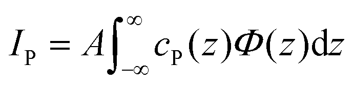 | (3) |
| ΓmP = fmP/AmL | (4) |
After adsorption of the DMPC–DMPG bilayer, two additional P-accommodating regions are considered, coinciding with the phospholipid headgroup slabs at the two bilayer surfaces. The P coverage in each of these regions is determined by the coverage fraction xb (see Results section) and the average lipid area AbL = 59.9 Å2 in a DMPC–DMPG bilayer in the Lα phase,40
| ΓbP = xbfbP/AbL | (5) |
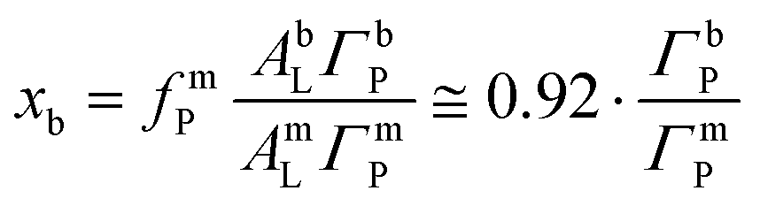 | (6) |
This coverage ratio, in turn, can be deduced from the ratio IP/I0p between the measured fluorescence intensities before and after bilayer adsorption (see Section 3.1.4).
3. Results and discussion
3.1. DMPC–DMPG bilayer supported by a DPPE–DSTAP monolayer
The preparation of conventional floating lipid bilayers15 is typically based on the Langmuir–Blodgett (LB) and/or Langmuir Schaefer (LS) techniques.9,41 This approach obviously cannot be taken for the deposition of lipid bilayers onto fluid interfaces and the vesicle fusion technique42,43 has to be employed instead. Although its effectiveness depends on many parameters, notably on a suitable functionalization of the interface, vesicle fusion has an overall greater potential to be used also for native membrane systems.44As in the case of solid-supported floating bilayers, a phospholipid surface is initially used as support for the bilayer deposition in the present work. For this purpose, a monolayer of DPPE–DSTAP (70:30 mol%) was chosen. The zwitterionic phospholipid DPPE has fully saturated C16 hydrocarbon chains and adopts a liquid-condensed (LC) state at 27 °C,45 the temperature at which this study was carried out. In order to promote the fusion of negatively charged vesicles we added to the monolayer 30 mol% of the positively charged lipid DSTAP, which has fully saturated C18 hydrocarbon chains and also forms a considerably rigid film.46 The lipids were spread onto an air–water interface from a chloroform–methanol (7:3 v/v) solution and then compressed until reaching a final lateral pressure of π = 30 mN m−1, a representative value of the packing in lipid bilayers.47Fig. 1 shows compression isotherms for the monolayers of the different lipidic mixtures employed during this work. The isotherm of the DPPE–DSTAP monolayer (red solid line) shows that the film transitions into an ordered LC phase already at very low pressures and is very stable up to π = 55 mN m−1.
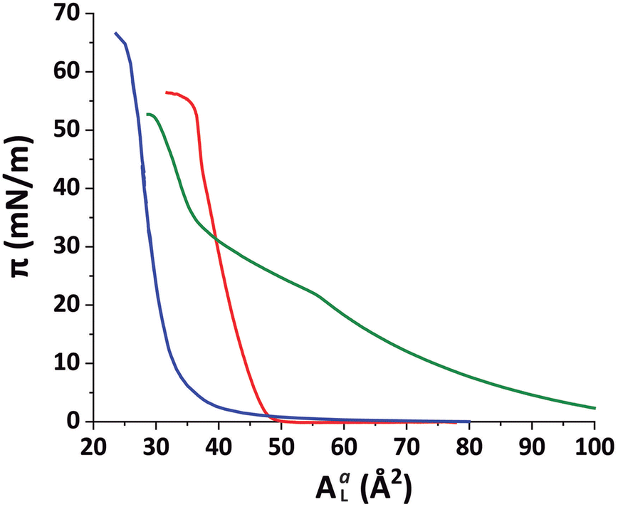 | ||
| Fig. 1 Compression isotherms (lateral pressure π vs. available area per molecule AaL) for DPPE–DSTAP (red), PFOL–PFOA (blue) and DMPC–DMTAP (green) mixed monolayers at 27 °C. AaL was calibrated with the crystallographic area ACL for each mixture at π = 30 mN m−1 (DPPE–DSTAP: ACL = 41.2 Å2; PFOL–PFOA: ACL = 29.1 Å2; DMPC–DMTAP: ACL = 44.6 Å2). | ||
Our purpose was to study bilayers in a fluid-like Lα phase. Therefore, the choice of a monolayer in an ordered LC phase was intended to minimize undesired lipid exchange between the adjacent mono- and bilayers. The SUVs for vesicle fusion were prepared using a 70:30 mol% mixture of DMPC and DMPG, a system that is negatively charged and assumes a fluid Lα phase at 27 °C, the temperature at which the measurements were conducted. The SUVs were slowly injected into the subphase under the pre-formed monolayer film (π = 30 mN m−1) with a syringe and from the opposite side of the compression barriers until reaching a final lipid concentration of 0.1 mg ml−1 in the subphase.
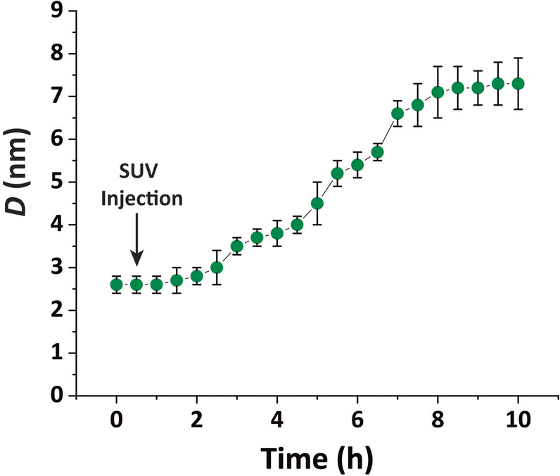 | ||
| Fig. 2 Total lipid layer thickness D obtained by ellipsometry as a function of time after the injection of DMPC–DMPG SUVs underneath a pre-formed DPPE–DSTAP monolayer at π = 30 mN m−1. The error bars correspond to the standard deviation of 4 independent experiments. | ||
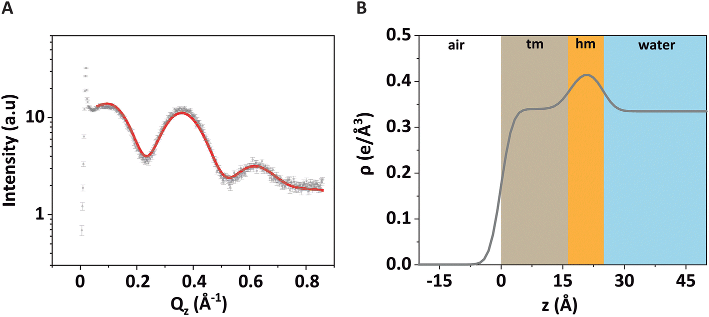 | ||
| Fig. 3 (A) GIXOS signal (symbols) from a DPPE–DSTAP monolayer at π = 30 mN m−1. The solid red line is the theoretical curve corresponding to the best-matching model parameters. (B) Reconstructed electron density profile of the monolayer at the air/water interface. The colored regions labeled with “tm” and “hm” represent the tail and headgroup sections, respectively, of the monolayer. | ||
The associated best-matching electron density profile is shown in Fig. 3B. The first layer has a comparatively low electron density and represents the tails of the monolayer (“tm”), while the second layer has a higher electron density and represents the headgroups of the monolayer (“hm”). The best-matching parameters are summarized in Table 1 and are similar to those reported earlier for a pure DPPE monolayer.48 The provided error estimates include systematic uncertainties, which are typically the dominant contribution as discussed previously.51
| d (Å) | ρ (e Å−3) | σ (Å) | ||
|---|---|---|---|---|
| hm | 8.1 ± 0.5 | 0.42 ± 0.01 | σ 1 (air/tm) | 2.2 ± 0.5 |
| tm | 16.8 ± 0.5 | 0.34 ± 0.01 | σ 2 (tm/hm) | 2.6 ± 0.5 |
| σ 3 (hm/water) | 2.4 ± 0.5 |
Note that the electron density in the headgroup is somewhat lower than in usual phospholipid layers, because here 30% of the lipids (DSTAP) do not have electron-rich P atoms in their headgroups. The comparatively high electron density of the tail layer is consistent with the reported structures of densely packed monolayers of lipids with saturated tails.52 The obtained roughness values are comparatively low, which can be attributed to the fact that GIXOS measures the scattering signal at finite Qxy.53
Fig. 4A shows the GIXOS curve measured 6 h after the injection of DMPC–DMPG SUVs underneath the DPPE–DSTAP monolayer. The solid line indicates the theoretical curve corresponding to the best-matching parameters of the slab model. This time, a more complex slab model was used to describe a bilayer adsorbed underneath the monolayer. In addition to the “tm” and “hm” slabs introduced before, slabs for the headgroups, tails, and the central methyl dip of the bilayer (“hb”, “tb”, and “mb”, respectively) as well as a water layer “w” between monolayer and bilayer were considered. Note that the “hb” and “tb” layers appear twice in the bilayer for reason of symmetry (see Fig. 4B). In order to minimize the number of free parameters in the model, the monolayer-related features were kept at the values obtained prior to vesicle fusion (Table 1). All bilayer-internal parameters were fixed such that they exactly reproduced (see Fig. S2 in ESI†) a previously published electron density profile of a DMPC bilayer in the fluid Lα phase.54 These fixed bilayer values are presented in Table 2. However, in order to realistically model an imperfect, fluctuating bilayer adsorbed to a monolayer, we further considered a global bilayer roughness, achieved by convolution of the bilayer profile with a Gaussian function of width σconv (see Table 3, 1st column). This was achieved analytically by correcting all bilayer-related slab roughness parameters as  . Moreover, we allowed for scenarios of incomplete bilayer coverage by introducing the coverage fraction xb∈[0, 1]. The latter was implemented through weighted averaging of the electron density profile of the bilayer (with weight xb) and of the constant electron density of water (with weight 1 − xb). The remaining free model parameters to fit the GIXOS intensity curve in Fig. 4A are only the thickness dw of the interstitial water layer, the global bilayer roughness σconv, and the bilayer coverage fraction xb.
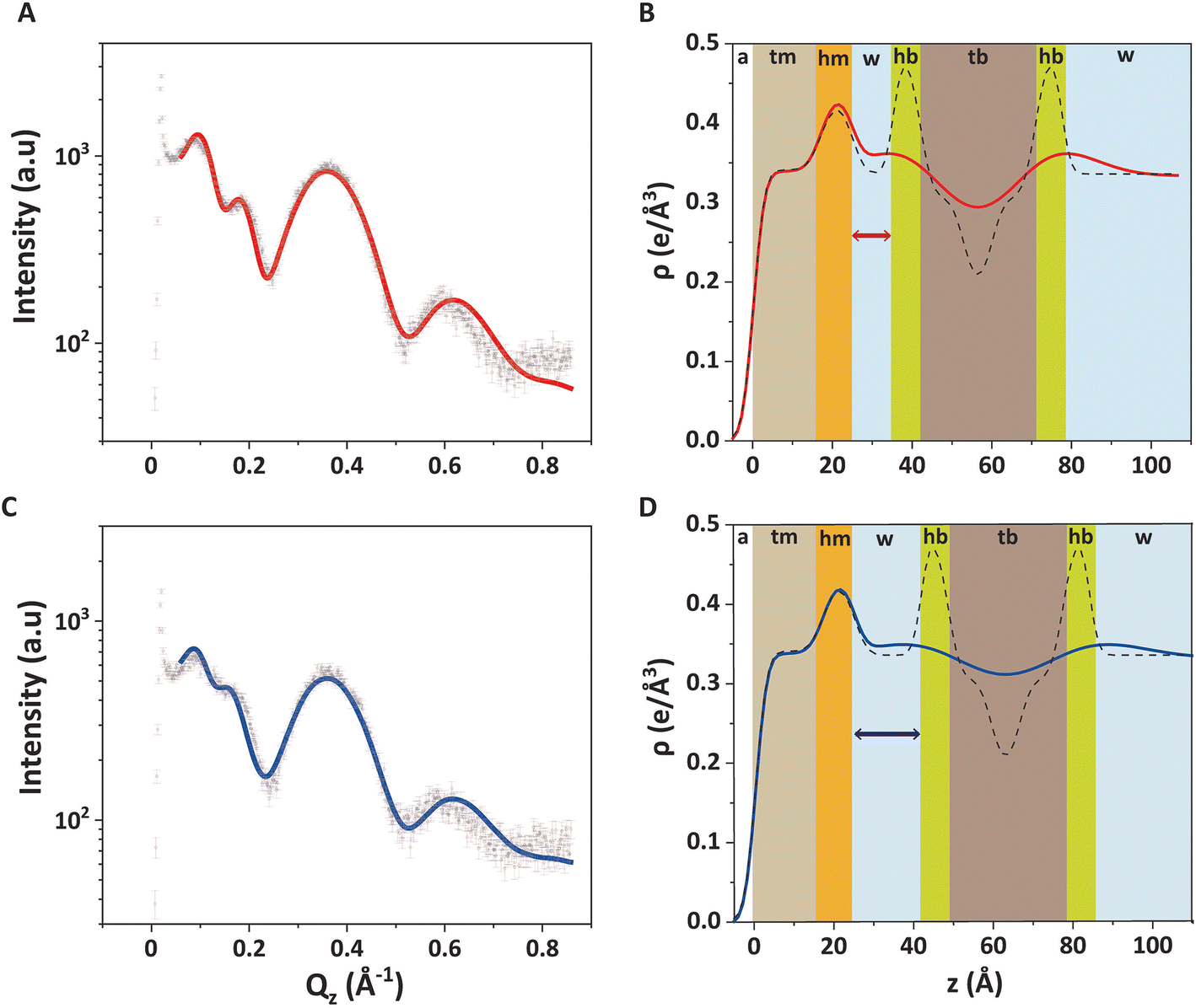 | ||
| Fig. 4 (A and C) GIXOS data (symbols) and the corresponding fits (solid lines) for the trilayer system (DPPE–DSTAP monolayer + adsorbed DMPC–DMPG bilayer) 6 hours after SUVs injection (A) without and (C) with added NaCl. (B and D) Reconstructed electron density profiles (solid lines) for the trilayer (B) without and (D) with added NaCl. The different colors represent the sections with different electron density values. The plots with dashed lines represent non-convolved electron density profiles, when setting σconv = 0 Å. All profiles represent the regions covered by a bilayer, i.e., for xb = 1. | ||
| d (Å) | ρ (e Å−3) | σ (Å) | ||
|---|---|---|---|---|
| hm | 8.1 | 0.42 | σ 1 (air/tm) | 2.2 |
| tm | 16.8 | 0.34 | σ 2 (tm/hm) | 2.6 |
| hb | 6.7 | 0.50 | σ 3 (hm/water) | 2.4 |
| tb | 10.9 | 0.30 | σ 4 (water/hb) | 1.8 |
| mb | 7.0 | 0.17 | σ 5 (hb/tb) | 2.4 |
| σ 6 (tb/mb) | 2.4 |
The good agreement between the theoretical GIXOS curve and the experimental data demonstrates the validity of the employed model upon optimization of these three parameters. In this case, the overall architecture of the trilayer can be roughly described as a 5 nm thick bilayer floating at a separation of ≈1 nm below a 2.5 nm thick monolayer, which is in good agreement with the ellipsometry results discussed before. Alternative sample architectures like multilayer formation can be excluded, as this would result in very different XRR and GIXOS curves and is also not expected in view of substantial electrostatic repulsion between like-charged bilayers.
The main obstacle to an unambiguous determination of the parameter values is a strong covariance between σconv and xb in the fit. Namely, a theoretical GIXOS or XRR curve undergoes similar changes when increasing xb or when decreasing σconv.‡ This undesirable ambiguity can however be circumvented through an independent determination of xb by TRXF measurements, as explained in Section 2.5.4.
An equivalent experiment on a monolayer/bilayer system of the same composition was performed by XRR with the same model-based analysis procedure. The XRR fitting curve (Fig. S3 and Table S1 in ESI†), like the GIXOS curve, is well reproduced by the model and the sample is clearly found to have the expected trilayer architecture. In fact, the agreement is satisfactory even when modelling the XRR experimental data with the model parameters found for in the GIXOS measurements (see again Fig. S3 in ESI†). While the main structural characteristics obtained by GIXOS and XRR are generally consistent, eventual differences can be attributed to the different roughness bias of the two techniques53 but also to the coverages that can be slightly different in two different experiments.
As stated above, our system was designed to minimize lipid exchange between the monolayer and the adsorbed bilayer, by working with a combination of long-chain lipids for the monolayer and short-chain lipids for the vesicles, which are rather immiscible at the imposed temperature. Nevertheless, we cannot exclude the possibility of some lipid exchange. The details of such exchange processes are best addressed by neutron reflectometry with selective deuteration, as was demonstrated for solid-supported bilayers exposed to vesicles8 and for lipid nanodiscs adsorbed to Langmuir monolayers.55 These works show that there can indeed be considerable lipid exchange between the interacting systems.
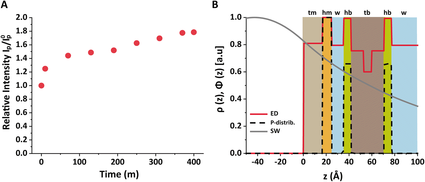 | ||
| Fig. 5 (A) Relative intensity IP/I0p as a function of time after SUVs injection. (B) Schematic illustration of the lipid layers with a slab description of the electron density profiles (red solid line), P distributions (black dashed line) and calculated SW X-ray intensity (grey solid line). | ||
As described in the Methods section, the bilayer coverage was deduced from the increase in the P fluorescence based on the interfacial SW profile and the distribution of P atoms. Fig. 5B shows the structure of the air/water interface after the bilayer adsorption in terms of the electron density slab model and the P distribution. The grey solid line indicates the SW intensity profile at the relevant incidence angle, which was found to be practically identical before and after bilayer adsorption. The profile was calculated with the monolayer and bilayer parameters summarized in Tables 1 and 2.54 Importantly, the SW intensity is higher at the monolayer surface than at the bilayer surfaces, which is why the bilayer contributes less to the P fluorescence intensity than the monolayer. Rigorous application of eqn (3) for both scenarios reproduces the observed intensity ratio IP/I0p = 1.77 when ΓbP/ΓmP = 0.54, such that the coverage fraction is obtained as xb = 0.50 according to eqn (6).
In other words, no full bilayer coverage was achieved after 6 h, which is consistent with the non-saturated P intensity in Fig. 5A and with the ellipsometry results which show that full coverage can take more than 8 h. By analyzing the ellipsometry results (Fig. 2), it can even be seen that the apparent bilayer thickness 6 hours after the vesicle injection represents a 59% fraction of the final stable bilayer thickness after 8 hours, in satisfactory agreement with the value xb = 0.50 obtained by TRXF.
The water layer thickness dw was found to be around 10 Å, in line with the picture that hydration repulsion prevents a direct surface contact despite the electrostatic attraction.56 With σconv ≈ 10 Å, the global bilayer roughness was found to be larger than that of conventional solid-supported lipid bilayers and comparable to that of floating lipid bilayers,15 reflecting the soft overall bilayer confinement at the functionalized air/water interface. To illustrate the influence of bilayer roughness, the non-convolved electron density profile (i.e., when assuming σconv = 0 Å) is also shown in Fig. 4B as a dashed line.
We further investigated the electrostatic effect of salt addition on the interaction of the DMPC–DMPG bilayer with the supporting DPPE–DSTAP monolayer. For this purpose, NaCl was added to a final concentration of 50 mM and another GIXOS measurement was carried out only 15 min later. The most remarkable effect caused by the salt addition is a water layer thickening (Table 3 and Fig. 4C, D) by around 7 Å (from dw ≈ 10 Å to dw ≈ 17 Å) which could be explained due to the screening of ions and the resulting weaker attraction between the oppositely charged layers. In fact, a similar value of dw (≈ 20 Å) has been previously reported for the separation between uncharged DPPC bilayers at full hydration,57 suggesting that hydration repulsion becomes the dominant short-range force contribution for sufficiently high ionic strength. The weaker adhesion strength in the presence of salt appears to correlate also with an increase in the bilayer roughness (see Table 3), as was previously discussed for solid-supported floating bilayers.15
In a related work by Wadsäter et al.,58 self-assembled lipid nanodiscs with an amphipathic protein belt were let adsorb to an oppositely charged surfactant monolayer at the air–water interface. Their results were similar to ours regarding the thickness of the intermediate water layer (15 Å in 100 mM NaCl). Regarding the surface coverage, which was reported to be around 66%, it must be noted that there exists an upper limit imposed by the optimal packing of spherical discs. Current work on bilayers suspended below functionalized air/water interfaces revealed a value of 11 Å for the water layer thickness in the presence of salts.66,67
3.2. DMPC–DMTAP bilayer supported by a PFOL–PFOA monolayer
The combination of GIXOS, TRXF, and ellipsometry allowed us to characterize the vertical sample architecture, i.e., perpendicular to the interface. In contrast, GIXD allows for the investigation of lipid layers in the in-plane direction and can resolve the details of the molecular arrangements in lipid phases with crystalline ordering.37,39 The technique is largely limited to air/water interfaces and has therefore been used almost exclusively for the study of lipid monolayers.52,59 However, having at hand lipid bilayers immobilized at air/water interfaces, we are in the unique position to exploit the power of GIXD for the study of lipid bilayers featuring phases with crystalline ordering, such as the chain-ordered Lβ phase.In order to distinguish the diffraction peaks from the monolayer and the bilayer, any overlap between the associated peak positions should be avoided, which is difficult when the monolayer is formed by conventional membrane lipids able to form ordered LC phases. To overcome this issue, a second experiment was performed in which the air/water interface was functionalized with a negatively charged monolayer formed by the perfluorinated amphiphiles 1H,1H-perfluorooctadecan-1-ol (PFOL) and perfluorooctadecanoic acid (PFOA), also in the molar proportion 70:30. The PFOL–PFOA isotherm (Fig. 1, blue solid line) was found to be featureless, steep, and stable up to π = 65 mN m−1, indicating densely arranged perfluorocarbon chain domains at all conditions. The SUVs were prepared from a positively charged mixture of DMPC–DMTAP (70:30 mol%). At 27 °C, an ordered Lβ structure is expected for this mixture, for which an Lβ to Lα phase transition temperature of ≈36 °C was reported by Zantl et al.60
The GIXOS curves of the compressed PFOL–PFOA monolayer (π = 30 mN m−1) prior to and after the injection of DMPC–DMTAP SUVs, clearly reveal the formation of a bilayer adsorbed to the monolayer (Fig. 6A and B). The fluorinated molecules of the monomolecular film were described as a single slab (labeled as “f”) with an adjusted thickness df ≈ 21 Å and an electron density ρf = 0.66 e Å−3 (Table 4) which agree well with those previously reported by Sperati61 and by Jacquemain62 for similar fluorinated compounds. The DMPC–DMTAP bilayer was modeled in the same way as the DMPC–DMPG bilayer discussed above, based on reference.54 Based on xb = 0.55, obtained by TRXF (see Methods section), the best-matching values for the two remaining parameters were obtained as dw ≈ 5 Å and σconv < 2 Å (see also Table 4). As can be seen, the interstitial water layer is significantly thinner than that of the DPPE–DSTAP–DMPC–DMPG system, which can be explained due to a much weaker hydration repulsion. In fact, it has been already reported that hydration repulsion is of much longer range for zwitterionic phospholipid surfaces than for surfaces bearing OH-groups.63 Besides, a stronger charge attraction can be attributed to a higher charge density in the monolayer. Regarding σconv we can assume that its remarkably low value is likely a consequence of the stronger adhesion and the overall higher rigidity of the perfluorinated monolayer.
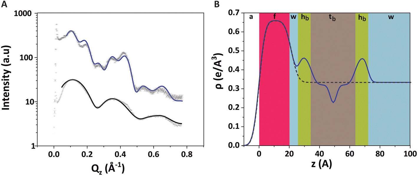 | ||
| Fig. 6 (A) GIXOS data (symbols) and the corresponding fits (solid lines) for the PFOL–PFOA (70:30 mol%) monolayer at π = 30 mN m−1 (black) and 6 h after injection of DMPC–DMPTAP SUVs (blue). (B) Reconstructed electron density profile for the monolayer (dashed line) and the trilayer (solid line). The different colours represent the sections with different electron density values. All profiles represent the regions covered by a bilayer, i.e., for xb = 1. | ||
| Parameters | |
|---|---|
| d f | 21.4 ± 0.5 Å |
| d w | 4.9 ± 0.5 Å |
| ρf | 0.66 ± 0.01 e Å−3 |
| x b | 0.55a |
| σ conv | 1.3 ± 0.5 Å |
| σ 1 (air/f) | 3.2 ± 0.5 Å |
| σ 2 (f/water) | 1.8 ± 0.5 Å |
Fig. 7A shows the GIXD pattern of the PFOL–PFOA monolayer prior to injection of DMPC–DMTAP SUVs. It exhibits a single sharp diffraction peak with the maximum at Qz = 0, indicating that the fluorocarbon chains assume an upright (un-tilted) hexagonal lattice. From the peak position Qxy = 1.268 Å−1 (Fig. 7A, inset), the corresponding lattice spacing between fluorocarbon chains of 5.72 Å can be calculated, which agrees well with the value reported earlier.64 Also for the shorter perfluorododecanoic acid (C11F23COOH) the same non-tilted phase has been observed between 15 and 50 mN m−1 with lattice-spacings decreasing from 5.83 Å to 5.77 Å on compression.65
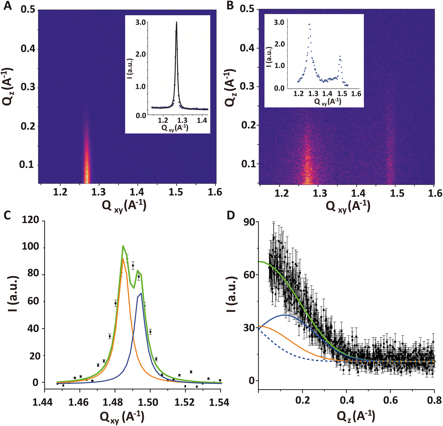 | ||
| Fig. 7 (A and B) GIXD contour plot obtained (A) for a PFOL–PFOA (70:30 mol%) monolayer at π = 30 mN m−1 and (B) for a PFOL–PFOA monolayer after formation of a DMPC–DMPG (70:30 mol%) bilayer. Qz – integrated intensities vs. Qxy are shown as insets in the respective plots. (C and D) Double-peak fit of the second intensity maximum at Qxy ≈ 1.49 A−1 emerging after bilayer formation. (C) Qz – integrated intensity vs. Qxy, where solid lines indicate the two Lorentzian fits as well as their sum. (D) Qxy – integrated intensity vs. Qz, where solid orange and blue lines indicate the modeled individual Gaussian peaks used for the model with fixed FWHM. The blue dashed curve indicates the tail of the mirror image of the blue curve, which also contributes to the intensity. The green line is the total model intensity. | ||
The GIXD pattern recorded 6 hours after the injection of DMPC/DMTAP SUVs features additional diffraction intensity around Qxy = 1.49 A−1, which can safely be attributed to the adsorbed bilayer (Fig. 7B). It should be noted that the measurements do not enable us to distinguish between the two bilayer leaflets with regard to their structural ordering. In other words, we cannot exclude a possible asymmetry in the chain ordering across the bilayer. The intensity of the diffraction signal coming from the bilayer is weaker compared to the one that would originate from a Langmuir monolayer with the same structure because the X-ray illumination profile decays exponentially with depth (see grey line in Fig. 5B). However, this effect is rather weak, with a relative reduction by a factor of less than 2.
The first impression is that this additional intensity is from a single diffraction peak centered at Qz ≈ 0, which would indicate a fully upright hexagonal packing of the lipid tails in the bilayer. However, the width of the peak in Qz-direction (FWHM = 0.41 A−1) according to the Scherrer equation24,37 corresponds to an alkyl chain layer thickness of only 14 Å, which is clearly too thin for a layer of stretched upright C14 tails. When a realistic value of L = 17 Å (corresponding to FWHM = 0.34 A−1) is imposed in a suitable model with two closely overlapping peaks, then fitting yields Qxy1 = 1.485 A−1, Qxy2 = 1.494 A−1, Qz1 = 0.12 A−1 and Qz2 = 0 A−1 (see Fig. 7C and D), which corresponds to a chain tilt of ≈5.3° and an area per molecule of AbL = 41.2 Å2. Note that in the work by Zantl et al. on the same lipid composition,60 the single intensity maximum observed in wide-angle X-ray scattering (WAXS) at Qxy ≈ 1.48 A−1 has also been interpreted as a superposition by powder averaging of the two separate peaks associated with a tilted chain lattice.
In contrast, in the monolayer of the DMPC–DMTAP (70:30 mol%) mixture, for which the isotherm is also shown in Fig. 1 (green solid line), three diffraction peaks are observed at high lateral pressures (see Fig. S4 in ESI†). They correspond to an LC phase with a crystallographic area per molecule of AmL = 44.6 Å2 and a chain tilt angle of α = 21.8°. Interestingly, the bilayer behaves differently than the monolayer of the same mixture, for which the tilt is much larger. As was already pointed out earlier, this result demonstrates the usefulness of GIXD experiments on lipid bilayers immobilized at air/water interfaces, as they allow for the investigation of bilayer structures that do not necessarily occur in the corresponding monolayers.19
Upon bilayer formation, also a slight lateral contraction in the fluorinated monolayer structure occurs, as manifested in a shift in the diffraction peak from Qxy = 1.268 A−1 to Qxy = 1.273 A−1. This molecular area decrease by roughly 1% could be related to an effective charge screening by the presence of the oppositely charged bilayer.
4. Conclusion
In this work we have successfully formed and characterized lipid bilayers adsorbed to functionalized air/water interfaces. Ellipsometry was proven to be a suitable technique to monitor the lipid layer total thickness and thus to follow the bilayer adsorption kinetics. GIXOS and XRR provide structural details of the layer architecture, while TRXF is a powerful complementary method to deduce the bilayer coverage fraction from the P fluorescence intensity. Finally, we demonstrated that the adsorbed bilayers can be structurally characterized in in-plane direction by GIXD, which opens new possibilities for future studies, for example on the formation of glycolipid-enriched functional domains.37Conflicts of interest
There are no conflicts to declare.Acknowledgements
We acknowledge DESY (Hamburg, Germany), a member of the Helmholtz Association HGF, for the provision of experimental facilities. Parts of this research were carried out at PETRA III and we would like to thank René Kirchhof (Chen Shen) and Milena Lippmann for assistance in using P08 and chemistry lab, respectively. Beamtime was allocated for proposals I-20191281 (June 2020) and I-20200672 (March 2021). Financial support by the German Research Foundation (DFG) via Emmy-Noether grant SCHN 1396/1 is gratefully acknowledged. We thank Giovanna Fragneto for fruitful discussions and Olaf Soltwedel for helping with XRR measurements.References
- M. Edidin, Nat. Rev. Mol. Cell Biol., 2003, 4, 414–418 CrossRef CAS PubMed.
- T. Heimburg, Thermal Biophysics of Membranes, Wiley VCH, 2007 Search PubMed.
- T. A. Harroun, J. Katsaras and S. R. Wassall, Biochemistry, 2006, 45, 1227–1233 CrossRef CAS PubMed.
- V. Rondelli, G. Fragneto, S. Motta, E. Del Favero, P. Brocca, S. Sonnino and L. Cantu, Biochim. Biophys. Acta, 2012, 1818, 2860–2867 CrossRef CAS PubMed.
- C. Chen, F. Pan, S. Zhang, J. Hu, M. Cao, J. Wang, H. Xu, X. Zhao and J. R. Lu, Biomacromolecules, 2010, 11, 402–411 CrossRef CAS.
- F. Heinrich and M. Losche, Biochim. Biophys. Acta, 2014, 1838, 2341–2349 CrossRef CAS.
- L. A. Clifton, F. Ciesielski, M. W. Skoda, N. Paracini, S. A. Holt and J. H. Lakey, Langmuir, 2016, 32, 3485–3494 CrossRef CAS.
- Y. Gerelli, L. Porcar, L. Lombardi and G. Fragneto, Langmuir, 2013, 29, 12762–12769 CrossRef CAS.
- L. K. Tamm and H. M. McConnell, Biophys. J., 1985, 47, 105–113 CrossRef CAS.
- E. Sackmann, Science, 1996, 271, 43–48 CrossRef CAS PubMed.
- F. Rehfeldt, R. Steitz, S. P. Armes, R. von Klitzing, A. P. Gast and M. Tanaka, J. Phys. Chem. B, 2006, 110, 9177–9182 CrossRef CAS.
- F. F. Rossetti, E. Schneck, G. Fragneto, O. V. Konovalov and M. Tanaka, Langmuir, 2015, 31, 4473–4480 CrossRef CAS.
- O. Purrucker, A. Fortig, R. Jordan and M. Tanaka, ChemPhysChem, 2004, 5, 327–335 CrossRef CAS PubMed.
- S. Hertrich, F. Stetter, A. Ruhm, T. Hugel and B. Nickel, Langmuir, 2014, 30, 9442–9447 CrossRef CAS PubMed.
- J. Daillant, E. Bellet-Amalric, A. Braslau, T. Charitat, G. Fragneto, F. Graner, S. Mora, F. Rieutord and B. Stidder, Proc. Natl. Acad. Sci. U. S. A., 2005, 102, 11639–11644 CrossRef CAS PubMed.
- R. Miller, J. K. Ferri, A. Javadi, J. Krägel, N. Mucic and R. Wüstneck, Colloid Polym. Sci., 2010, 288, 937–950 CrossRef CAS.
- C. Stefaniu, G. Brezesinski and H. Mohwald, Adv. Colloid Interface Sci., 2014, 208, 197–213 CrossRef CAS.
- G. Brezesinski and H. Möhwald, Adv. Colloid Interface Sci., 2003, 100–102, 563–584 CrossRef CAS PubMed.
- E. B. Watkins, C. E. Miller, W. P. Liao and T. L. Kuhl, ACS Nano, 2014, 8, 3181–3191 CrossRef CAS PubMed.
- R. M. A. Azzam, N. M. Bashara and S. S. Ballard, Phys. Today, 1978, 31(11), 72 CrossRef.
- R. Reiter, H. Motschmann, H. Orendi, A. Nemetz and W. Knoll, Langmuir, 1992, 8, 1784–1788 CrossRef CAS.
- C. Appel, M. Kraska, C. Ruttiger, M. Gallei and B. Stuhn, Soft Matter, 2018, 14, 4750–4761 RSC.
- L. G. Parratt, Phys. Rev., 1954, 95, 359 CrossRef.
- J. Als-Nielsen and D. McMorrow, Elements of Modern X-ray Physics, John Wiley & Sons, Ltd, 2nd edn, 2011 Search PubMed.
- W. B. Yun and J. M. Bloch, J. Appl. Phys., 1990, 68(4), 1421–1428 CrossRef CAS.
- E. Schneck, T. Schubert, O. V. Konovalov, B. E. Quinn, T. Gutsmann, K. Brandenburg, R. G. Oliveira, D. A. Pink and M. Tanaka, Proc. Natl. Acad. Sci. U. S. A., 2010, 107, 9147–9151 CrossRef CAS.
- G. Brezesinski and E. Schneck, Langmuir, 2019, 35, 8531–8542 CrossRef CAS PubMed.
- L. Bosio, J. J. Benattar and F. Rieutord, Rev. Phys. Appl., 1987, 22, 775–778 CrossRef CAS.
- C. A. Helm, H. Möhwald, K. Kjaer and J. Als-Nielsen, EPL, 1987, 4, 697–703 CrossRef CAS.
- S. Mora, J. Daillant, D. Luzet and B. Struth, Europhys. Lett., 2004, 66, 694–700 CrossRef CAS.
- S. M. O'Flaherty, L. Wiegart, O. Konovalov and B. Struth, Langmuir, 2005, 21, 11161–11166 CrossRef.
- L. Wiegart, S. M. O'Flaherty, P. Terech and B. Struth, Soft Matter, 2006, 2, 54–56 RSC.
- R. Dalgliesh, Curr. Opin. Colloid Interface Sci., 2002, 7, 244–248 CrossRef CAS.
- L. Wiegart, B. Struth, M. Tolan and P. Terech, Langmuir, 2005, 21, 7349–7357 CrossRef CAS.
- R. G. Oliveira, E. Schneck, B. E. Quinn, O. V. Konovalov, K. Brandenburg, T. Gutsmann, T. Gill, C. B. Hanna, D. A. Pink and M. Tanaka, Phys. Rev. E: Stat., Nonlinear, Soft Matter Phys., 2010, 81, 041901 CrossRef.
- M. Kanduč, E. Schneck and C. Stubenrauch, J. Colloid Interface Sci., 2021, 586, 588–595 CrossRef.
- T. Mukhina, G. Brezesinski, C. Shen and E. Schneck, J. Colloid Interface Sci., 2022, 615, 786–796 CrossRef CAS.
- V. M. Kaganer, H. Möhwald and P. Dutta, Rev. Mod. Phys., 1999, 71, 779–819 CrossRef CAS.
- K. Kjaer, J. Als-Nielsen, C. A. Helm, L. A. Laxhuber and H. Mohwald, Phys. Rev. Lett., 1987, 58, 2224–2227 CrossRef CAS.
- T. Broemstrup and N. Reuter, Biophys. J., 2010, 99, 825–833 CrossRef CAS.
- J. Kurniawan, J. F. Ventrici de Souza, A. T. Dang, G. Y. Liu and T. L. Kuhl, Langmuir, 2018, 34, 15622–15639 CrossRef CAS.
- K. Kamiya, C. Arisaka and M. Suzuki, Micromachines, 2021, 12(2), 133 CrossRef.
- M. Seitz, E. Ter-Ovanesyan, M. Hausch, C. K. Park, J. A. Zasadzinski, R. Zentel and J. N. Israelachvili, Langmuir, 2000, 16, 6067–6070 CrossRef CAS PubMed.
- M. Tanaka, S. Kaufmann, J. Nissen and M. Hochrein, Phys. Chem. Chem. Phys., 2001, 3(18), 4091–4095 RSC.
- D. Gidalevitz, Y. Ishitsuka, A. S. Muresan, O. Konovalov, A. J. Waring, R. I. Lehrer and K. Y. Lee, Proc. Natl. Acad. Sci. U. S. A., 2003, 100, 6302–6307 CrossRef CAS PubMed.
- B. Moghaddam, S. E. McNeil, Q. Zheng, A. R. Mohammed and Y. Perrie, Pharmaceutics, 2011, 3, 848–864 CrossRef CAS.
- D. Marsh, Biochim. Biophys. Acta, 1996, 1286, 183–223 CrossRef CAS.
- D. F. Kienle, J. V. de Souza, E. B. Watkins and T. L. Kuhl, Anal. Bioanal. Chem., 2014, 406, 4725–4733 CrossRef CAS.
- M. C. Howland, A. W. Szmodis, B. Sanii and A. N. Parikh, Biophys. J., 2007, 92, 1306–1317 CrossRef CAS PubMed.
- N. Kucerka, M. A. Kiselev and P. Balgavy, Eur. Biophys. J., 2004, 33, 328–334 CrossRef CAS PubMed.
- I. Rodriguez-Loureiro, E. Scoppola, L. Bertinetti, A. Barbetta, G. Fragneto and E. Schneck, Soft Matter, 2017, 13, 5767–5777 RSC.
- C. Stefaniu, V. M. Latza, O. Gutowski, P. Fontaine, G. Brezesinski and E. Schneck, J. Phys. Chem. Lett., 2019, 10, 1684–1690 CrossRef CAS PubMed.
- Y. Dai, B. Lin, M. Meron, K. Kim, B. Leahy and O. G. Shpyrko, J. Appl. Phys., 2011, 110(10), 102213 CrossRef.
- H. I. Petrache, S. Tristram-Nagle and J. F. Nagle, Chem. Phys. Lipids, 1998, 95, 83–94 CrossRef CAS.
- G. Hazell, T. Arnold, R. D. Barker, L. A. Clifton, N. J. Steinke, C. Tognoloni and K. J. Edler, Langmuir, 2016, 32, 11845–11853 CrossRef CAS PubMed.
- E. Schneck, F. Sedlmeier and R. R. Netz, Proc. Natl. Acad. Sci. U. S. A., 2012, 109, 14405–14409 CrossRef CAS PubMed.
- L. J. Lis, M. McAlister, N. Fuller, R. P. Rand and V. A. Parsegian, Biophys. J., 1982, 37, 657–665 CrossRef CAS.
- M. Wadsäter, J. B. Simonsen, T. Lauridsen, E. G. Tveten, P. Naur, T. Bjornholm, H. Wacklin, K. Mortensen, L. Arleth, R. Feidenhans'l and M. Cardenas, Langmuir, 2011, 27, 15065–15073 CrossRef.
- C. Stefaniu and G. Brezesinski, Adv. Colloid Interface Sci., 2014, 207, 265–279 CrossRef CAS.
- R. Zantl, L. Baicu, F. Artzner, I. Sprenger, G. Rapp and J. O. Rädler, J. Phys. Chem. B, 1999, 103, 10300–10310 CrossRef CAS.
- C. Sperati, in Polymer Handbook, ed. J. Brandrup and E. Immergut, John Wiley and Sons, New York, 1989 Search PubMed.
- D. Jacquemain, S. Grayer Wolf, F. Leveiller, M. Deutsch, K. Kjaer, J. Als-Nielsen, M. Lahav and L. Leiserowitz, Angew. Chem., Int. Ed. Engl., 1992, 31(2), 130–152 CrossRef.
- M. Kanduc, A. Schlaich, A. H. de Vries, J. Jouhet, E. Marechal, B. Deme, R. R. Netz and E. Schneck, Nat. Commun., 2017, 8, 14899 CrossRef CAS PubMed.
- J. Oelke, A. Pasc, A. Wixforth, O. Konovalov and M. Tanaka, Appl. Phys. Lett., 2008, 93(21), 213901 CrossRef.
- P. Fontaine, E. J. M. Filipe, M. C. Fauré, T. Rego, S. Taßler, A. C. Alves, G. M. C. Silva, P. Morgado and M. Goldmann, Molecules, 2019, 24(19), 3590 CrossRef CAS.
- S. Ayscough, PhD thesis, The University of Edinburgh, 2020 Search PubMed.
- S. Ayscough, S. Titmuss, L. A. Clifton and M. W. A. Skoda, ChemRxiv, 2022. This content is a preprint and has not been peer-reviewed.
Footnotes |
| † Electronic supplementary information (ESI) available. See DOI: https://doi.org/10.1039/d2nr03334h |
| ‡ This is the case for X-rays, because bilayers on average have similar ρ as water and contrast therefore mainly arises from bilayer internal ρ variations which vanish when getting smeared out by convolution. For neutrons, the situation is different. |
| This journal is © The Royal Society of Chemistry 2022 |