Designing optimal core–shell MOFs for direct air capture

Paul Boone a, Yiwen He b, Austin R. Lieber c, Janice A. Steckel d, Nathaniel L. Rosi ab, Katherine M. Hornbostel ac and Christopher E. Wilmer *ae
aDepartment of Chemical and Petroleum Engineering, University of Pittsburgh, Pittsburgh, Pennsylvania 15261, USA. E-mail: wilmer@pitt.edu
bDepartment of Chemistry, University of Pittsburgh, Pittsburgh, Pennsylvania 15260, USA
cDepartment of Mechanical Engineering & Materials Science, University of Pittsburgh, Pittsburgh, Pennsylvania 15261, USA
dUnited States Department of Energy, National Energy Technology Laboratory, Pittsburgh, PA 15236, USA
eDepartment of Electrical and Computer Engineering, University of Pittsburgh, Pittsburgh, Pennsylvania 15261, USA

Received 9th June 2022 , Accepted 23rd August 2022

First published on 23rd August 2022


Abstract

Metal–organic frameworks (MOFs), along with other novel adsorbents, are frequently proposed as candidate materials to selectively adsorb CO2 for carbon capture processes. However, adsorbents designed to strongly bind CO2 nearly always bind H2O strongly (sometimes even more so). Given that water is present in significant quantities in the inlet streams of most carbon capture processes, a method that avoids H2O competition for the CO2 binding sites would be technologically valuable. In this paper, we consider a novel core–shell MOF design strategy, where a high-CO2-capacity MOF “core” is protected from competitive H2O-binding via a MOF “shell” that has very slow water diffusion. We consider a high-frequency adsorption/desorption cycle that regenerates the adsorbents before water can pass through the shell and enter the core. To identify optimal core–shell MOF pairs, we use a combination of experimental measurements, computational modeling, and multiphysics modeling. Our library of MOFs is created from two starting MOFs-UiO-66 and UiO-67-augmented with 30 possible functional group variations, yielding 1740 possible core–shell MOF pairs. After defining a performance score to rank these pairs, we identified 10 core–shell MOF candidates that significantly outperform any of the MOFs functioning alone.

1 Introduction

Negative emissions technologies such as direct air capture (DAC) are necessary to limit planetary warming.1 There are now several companies with DAC pilot plants, such as ClimeWorks, Carbon Engineering and Global Thermostat, whose processes are based on aqueous or solid sorbents that capture CO2 and a vacuum or temperature swing to regenerate the sorbent that utilizes waste heat.2–8 However, scaling these pilot plants from the current total of 6500 t CO2 per year to the required scale of >12 Gt CO2 per year is a non-trivial process that will strain global resource limitations on water, energy and land.9 To make the resource cost of DAC more manageable, there need to be novel breakthroughs in both material design and process design.

DAC technologies typically consist of either solvents or sorbents that remove CO2 from the atmosphere, where it is present at very low concentration (∼400 ppm). Most sorbents require lower regeneration temperatures but larger facilities to obtain the same capture capacity as their solvent counterparts.10–13 It is possible to reduce a sorbent-based DAC facility's size and capture cost by improving the sorbent through chemical functionalization or coupling the sorbent with an additional material, either via surface coatings or impregnation. In prior work, a composite material of the metal–organic framework (MOF) NbOFFIVE-1-Ni@PA affixed to the surface of polyacrylate (PA) led to a CO2 loading capacity improvement of 10.8% relative to the lone MOF.14 Additionally, coupling sorbents, which typically have poor thermal conductivities, with unorthodox processes has been shown to lead to lower regeneration duty requirements. For example, microwave-assisted desorption of CO2 saturated Lewatit VP OC 1065 (benzylamine-functionalized, porous polystyrene particles) showed marked improvement in productivity compared to temperature and/or pressure swing desorption due to the use of radiative heating.15

Here we consider novel MOF designs to achieve higher performance in a DAC process. MOFs are a promising and very tunable class of materials; inorganic metal centers and organic ligands can be combined in different ways to create porous materials of varying geometries and surface chemistries.16 Over 90[thin space (1/6-em)]000 MOFs have been synthesized to date17 and have demonstrated uses for gas storage, gas separation, catalysis and more.18 However, it can still be difficult to design a single MOF that fulfills all of the requirements of a challenging process. One particular challenge of using MOFs in a DAC process is that water is present in the atmosphere at higher concentrations than CO2, and typically adsorption sites that bind strongly to CO2 bind even more strongly to H2O, leading to unfavorable competitive adsorption. The presence of water may also negatively affect the stability of the MOF.19–21 A MOF with otherwise very high CO2/N2 selectivity may not be viable under humid conditions for a DAC process.

One means of addressing this problem is by constructing a stratified MOF,22 the simplest being a “core–shell” MOF consisting of a core MOF surrounded by a shell of another MOF.23 The resulting composite material can exhibit unique properties that neither individual MOF possesses. The first core–shell MOFs were synthesized in 200924,25 and core–shell MOFs have shown promise for a number of applications23 and specifically for CO2 separation and capture.26–28

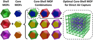
Furthermore, a vast quantity of different stratified MOFs is possible from even a small basis set of individual chemical components. The properties of such MOFs would derive from the compositions of the individual strata and the sequence of those strata in the hierarchical structure. It would be time-consuming and impractical to synthesize every possible combination of materials to identify ideal strata compositions and sequences for a specified process and set of properties. We can greatly accelerate this discovery process by computationally screening a wide set of materials to identify promising MOFs and combinations to pursue in the lab. To the best of our knowledge, there have not been any attempts to develop process conditions for CO2 capture specific to core–shell MOF materials, or to attempt to identify promising core–shell MOF candidates for CO2 capture computationally (Fig. 1).


image file: d2nr03177a-f1.tif
Fig. 1 Overview of the strategy for designing optimal core–shell MOFs for DAC. A library of MOFs is combinatorically assembled into all of the possible core–shell MOF pairs, and then each pair is computationally evaluated to find candidates for experimental synthesis. Optimal designs should prevent H2O from reaching the core while allowing for significant CO2 adsorption in the core. Note that we include in our consideration core–shell MOF “pairs” where the core and the shell are the same MOF.

The purpose of this work is to identify core–shell MOFs that outperform their constituent MOFs in a DAC process. We define a ranking methodology to score all potential core–shell MOF pairs and identify 10 core–shell MOF pairs that have a performance at least 25% greater than their core or shell individually.

Certain selected MOFs were synthesized experimentally and their single component N2, CO2, and H2O isotherms were collected. Sorption selectivities were calculated and compared to predictions to validate the computational approach. One core–shell MOF combination, amino1⊂methyl2, was then simulated in COMSOL Multiphysics® to demonstrate the core–shell concept at the pellet scale.

2 Methodology

2.1 Overview

We chose UiO-66 and UiO-6729 (Fig. 2) as our base MOFs (original MOFs that will be modified with different functional groups) because they are good candidates for CO2 capture due to their high adsorption selectivity of CO2 over N2.20,30 To create our MOF library, we substituted one or more hydrogens on the linkers with 16 functional groups (see Fig. 3), chosen to represent a variety of possible chemical motifs, from fluorinated and methylated groups to alkane chains and rings. For many of the functional groups, we allowed for substitution either once or twice per linker, resulting in 30 different forms of each base MOF. Because the base MOFs UiO-66 and UiO-67 have different unit cell sizes, a core–shell MOF can't be a mix of both MOFs; the core–shell MOF must be composed of one kind or the other. However, 30 functional variations per base MOF makes possible about 302 core–shell MOF combinations per base MOF.
image file: d2nr03177a-f2.tif
Fig. 2 UiO-67 (left) and UiO-66 (right) structures showing biphenyl and phenyl ligands.

image file: d2nr03177a-f3.tif
Fig. 3 Chemical diagrams of functional groups used to modify UiO-66 and UiO-67 linkers.

2.2 Idealized adsorption/desorption cycle

In this study, we assume an idealized adsorption/desorption cycle (as shown in Fig. 4), where the adsorption step is carried out over a time scale such that CO2 saturates the core MOF but before water is able to diffuse through the shell MOF. In our model process, we assume that spherical pellets of a core–shell MOF are arranged in a shallow bed reactor, such that every pellet is exposed simultaneously to the input gas stream at the onset of the adsorption step. The input gas stream is assumed to be at atmospheric temperature, pressure, and humidity, all of which depend on the time of day, the season of year, the weather, and other factors. For the purposes of this model, we are assuming the input gas stream is 298 K, with partial pressures of 42 Pa CO2, 79 kPa N2 and 50% relative humidity.
image file: d2nr03177a-f4.tif
Fig. 4 Schematic overview of our idealized adsorption/desorption cycle process used to investigate core–shell MOF candidates. We assume 100% evacuation of adsorbed gases during the desorption step, which can be mediated via imposing a vacuum or raising the temperature (or both), but in this idealized model the specific desorption conditions are intentionally ignored.

With a shell that allows for faster CO2 diffusion as compared to water, the CO2 will reach the core before the water. The results of this process are dependent on the exact timing of the switch from adsorption to regeneration: too early and very little CO2 reaches the core, too late and both the core and shell reach equilibrium loading (i.e., where the core would be saturated with H2O). In both cases, there would be no benefit to using a core–shell MOF design. Therefore, a core–shell MOF process requires thoughtful design and timing to be effective.

In this work we are sizing the pellets so that the water in the input gas stream breaks through into the core at 100 seconds, at which time the pellets are regenerated. For simplicity, we assume 100% evacuation of all gases during the regeneration step, and so in this idealized model we do not specify whether desorption is due to imposing a vacuum, raising of the temperature of the reactor bed, or both.

For this process to be selective for CO2, the shell MOF of the pellet must be diffusion-selective for CO2 over H2O, and the core MOF must be adsorption-selective for CO2 over N2. This process is designed to allow different core–shell MOF combinations to be directly compared, and as a proof of concept demonstrating the viability of using a core–shell MOF for direct air capture.

2.3 Experimental

To compare with the simulation results, five MOFs, UiO-67, amino1-UiO-67, amino2-UiO-67, methyl1-UiO-67, and methyl2-UiO-67 were synthesized and characterized. The structures, compositions, and porosities of these MOFs were determined. CO2, N2 and water vapor sorption isotherms at 298 K were collected, and these data were then used to calculate experimental adsorption selectivity (see ESI section 2).

2.4 Determination of water breakthrough times and pellet loadings

First, we calculate the breakthrough time of water according to the system shown in Fig. 5. Let x = 0 be the boundary between the core–shell MOF pellet and the gas stream, let x = x0 be the boundary between the core MOF and the shell MOF, and let x = x1 be an arbitrary limit to the core MOF. The concentration profile of a gas in this system can be calculated using the diffusion equation, a Dirichlet boundary condition at x = 0, and a Neumann boundary condition at x = x1:
 
image file: d2nr03177a-t1.tif(1)
 
At x = 0, cgas = Agas,eq(2)
 
At x = x1, ∂cgas/∂x = 0(3)

image file: d2nr03177a-f5.tif
Fig. 5 A 1-D infinite slab model of the outer region of a core–shell MOF used to estimate breakthrough times and fluxes of both H2O and CO2.

Here, cgas is the concentration of the gas, Dgas is the diffusivity of the gas, and Agas,eq is the equilibrium adsorption of the gas in the shell MOF. This partial differential equation can be solved analytically and is used to determine breakthrough times for both CO2 and H2O at x = x0.

There are two major notes to consider here. The first is that the properties of the core are not being considered at this point, and the diffusivity of the shell is applied across the entire system 0 ≤ xx1. The rationale for including a core region, even though we are only interested in calculating shell properties, is to allow the concentrations and fluxes at the core–shell boundary to vary (i.e., not to be fixed) while maintaining simple boundary conditions elsewhere. For calculating breakthrough times through the shell, the diffusivity of the core should not significantly affect this calculation, and this simplification is necessary in order to evaluate a shell independently from a core. The second note to consider is that we are explicitly using the infinite slab version of the diffusion equation, not the spherical form. This is because we will be sizing the particles based on the results of the calculated breakthrough times so the radius of the core and the thickness of the shell are not known in advance. A more detailed 2D multi-physics model with spherical geometry is described below in section 3.6.

We define the breakthrough time of a gas into the core as the smallest time (t = τgas) such that cgas(x = x0, τgas) ≥ 0.01·cCO2, eq. In other words, the breakthrough time of a gas (τgas) occurs when the concentration of the gas (cgas) at the core–shell MOF boundary (x0) is greater than 1% of the equilibrium loading of CO2 (cCO2, eq).

For each core–shell MOF, the thickness of the shell (x0) is chosen so that the breakthrough time of H2O (τH2O) equals 100 seconds. The breakthrough time of CO2 (τCO2) is calculated using this x0. We assume a flux of CO2 through the shell to the core based on the solution diffusion model.

 
image file: d2nr03177a-t2.tif(4)

The core is sized so that at 100 seconds the core will be fully loaded with CO2, given the flux j and assuming the core–shell MOF is a sphere. At 100 seconds, the total loading of H2O in moles (MH2O) is calculated as the surface area of the core with radius (rcore) multiplied by the integral of the concentration profile:

 
image file: d2nr03177a-t3.tif(5)

We assume N2 reaches equilibrium loading in both the shell and core, MN2 = AN2, eq, shell·Vshell + AN2,eq,core·Vcore, and CO2 reaches equilibrium loading only in the core: MCO2 = ACO2,eq,core·Vcore. In this calculation, CO2 loading of the shell is intentionally neglected because we assume H2O will out-compete CO2 for binding sites (note that this is a conservative assumption, as any CO2 captured in the shell would improve process performance). At 100 seconds the core–shell MOF is regenerated and complete evacuation of all N2, CO2 and H2O in the core–shell MOF is assumed.

2.5 Scoring of core–shell MOF pairs

Core–shell MOFs are scored as the output stream CO2 concentration of the core–shell MOF divided by the output stream CO2 concentration of standalone UiO-67:
 
image file: d2nr03177a-t4.tif(6)
C⊂S denotes the core⊂shell MOF (e.g. trifluoromethyl2⊂amino1). This gives us a dimensionless number where values are a multiple (or fraction) of the CO2 concentration in the output stream of a non-functionalized non-core–shell MOF UiO-67 under the same process. The main purpose of the scores is not to predict the absolute CO2 concentration of the output gas stream but to be able to fairly compare different core–shell MOF pairs and rank them compared to each other and the individual core and shell that they are composed of.

For the core to saturate with CO2 by the breakthrough time of water, the CO2 diffusivity of the core must be similar to the CO2 diffusivity of the shell. To ensure that we are only pairing shells with cores that have comparable CO2 diffusivity, we set the score to 0 for any core that has CO2 diffusivity <1/10 that of the shell.

2.6 COMSOL Multiphysics® modeling

A multiphysics model of a spherical core–shell pellet was developed in COMSOL Multiphysics® to simulate the diffusion and adsorption of CO2 and H2O in a macro-scale core–shell MOF. This model is 2D-axisymmetric along the centerline of the pellet, as shown in Fig. 6. The core size and shell thickness for a given core–shell MOF was chosen to match the same properties in our scoring model. For the example amino1⊂methyl2, this is a 0.453 cm radius core and a 0.04 cm thickness shell.
image file: d2nr03177a-f6.tif
Fig. 6 Setup of COMSOL Multiphysics® model of a single core–shell spherical pellet. Air flows in from the bottom over a 0.453 cm radius core + 0.04 cm thick shell pellet.

Adsorption of CO2, N2 and H2O was modeled in COMSOL by curve-fitting the following Langmuir equation to experimental isotherm data:

 
image file: d2nr03177a-t5.tif(7)
where CP,i [mol kg−1] is the concentration of gas adsorbed, CP,max,i [mol kg−1] is the maximum amount of gas the MOF can hold, KL,i [m3 mol−1] is the Langmuir constant, and Ci [kg m−3] is the concentration of available gas to adsorb. The Langmuir curve fits along with the fitted values for the constants in this equation are provided in the ESI, section 3.

2.7 Adsorption and diffusion simulations

For every functionalized MOF, we ran molecular dynamics simulations in the NVT ensemble and calculated self-diffusion coefficients for CO2, N2, and H2O. We also performed grand canonical Monte Carlo (GCMC) simulations to calculate adsorption of CO2 and N2 and used the Widom insertion method31 to determine Henrys constants for H2O. CO2 and N2 were modeled using the TraPPE32 force field parameters and H2O was modeled using TIP4P.33,34 Framework charges were calculated using EQeq35 and the framework atoms were modeled with Lennard-Jones parameters from UFF.36 Experimental N2, CO2, and H2O isotherms were collected and the Henry's constant selectivities were calculated for comparison to the computational results. We employed custom force-field parameters for the NH2–CO2 interaction to better reflect chemisorption. Full details can be found in the ESI, section 1.

3 Results and discussion

Molecular simulations of gas adsorption and diffusion were carried out on all MOFs, followed by calculations using a 1-D infinite slab model to determine water breakthrough times in every shell MOF candidate. These various data were then used to score every core–shell MOF combination in order to rank them from best to worst. In addition to validating the simple 1-D slab model using finite element modeling with COMSOL Multiphysics®, we also synthesized certain MOF combinations and measured the adsorption of CO2 and N2.

Calculated gas loadings varied from about 1 e−2 to 1 e1 V/V (cm3 gas STP per cm3 framework) with most functional groups having N2 loading > H2O loading > CO2 loading (see selected MOFs in Fig. 7a). This ordering follows the relative partial pressures of each species in the ambient environment. The fluorinated groups fluoro8 and trifluoromethyl2 are notable exceptions, showing very high H2O loading. Diffusivities varied more widely, from about 1 e−7 to 3 e−2 Å2/fs, with most MOFs having a N2 diffusivity > CO2 diffusivity > H2O diffusivity (see selected MOFs in Fig. 7b). There are some MOFs that do not show the same diffusivity ordering, but those have very low diffusivity and very high uncertainty, such as cyclohexylamino2.


image file: d2nr03177a-f7.tif
Fig. 7 (a) Gas loadings of CO2, N2 and H2O for selected MOFs based on UiO-67. Vertical lines are the amount of each gas in the atmosphere. (b) Diffusivities of CO2, N2 and H2O for selected MOFs based on UiO-67, with error bars to 95% confidence interval.

The simulated gas loadings can be validated by comparing the adsorption selectivity of CO2/N2 calculated using both the predicted gas loadings and the experimentally measured gas loadings (see ESI, section 2.4.5). The predicted selectivities exhibit a similar trend within UiO-67, methyl-UiO-67, methyl2-UiO-67 and UiO-67, amino-UiO-67, amino2-UiO-67, respectively (Fig. S10 and S11). However, when comparing amino- and methyl-functionalized MOFs, the simulation and experimental results do not follow a similar trend (Fig. S12 and S13), prior to our adjustment of the NH2–CO2 interaction force field terms, which is due to chemisorptive effects not being modeled in the non-adjusted simulation model (more detail can be found in the ESI 1.4). Overall, general agreement between experimentally and computationally derived selectivities provides confidence that our models can be reasonably used to rank candidate MOF materials.

For UiO-66, there was no observable diffusion in 21 of 28 functionalized structures at the timescales simulated; this is likely because the pore size of UiO-66 is too small to reasonably pack larger functional groups into the empty space, leaving no room for a gas to diffuse through a rigid framework. Of the remaining functionalized structures, only one has a positive diffusive selectivity for CO2 over H2O: fluoro4-UiO-66. However, this fluorine group has a very high adsorption of water, which will cause the perm-selectivity of CO2/H2O to be less than one, making it selective for water over CO2. Therefore, none of the screened UiO-66-based MOFs are suitable as candidates for the shell. Since the layers within stratified MOFs should have similar unit cell parameters, we therefore will only be considering and scoring UiO-67 functional groups as potential core–shell MOFs.

For UiO-67, some of the denser functional groups, such as the hydrocarbons with two groups per linker reported no diffusion, likely due to similar causes as UiO-66. For all other groups, we have diffusivity data, and largely all structures are diffusion selective for CO2 over H2O. There are many different functionalized UiO-67 structures to choose from for a core–shell MOF. Diffusivities and gas loadings for all functionalized MOFs can be seen in Fig. S2 and 3.

When evaluating UiO-67-based core–shell MOF scores, we are looking for two things: (1) a score that is higher than both its individual core or shell under the same process, and (2) a high absolute score. Scores for all core–shell MOF combinations are shown in Fig. 8 and there are examples of core–shell MOFs that outperform their constituent core and shell, and core–shell MOFs that underperform.


image file: d2nr03177a-f8.tif
Fig. 8 Scores for all UiO-67-based core–shell MOF combinations (excluding any MOF where all core–shell MOFs derived from it had scores less than 1.0). Black boxes are a guide to highlight the scores for non-core–shell MOFs under the same process. Numbers indicate every core–shell MOF combination where the combination has a higher score than both MOFs that compose it. Bold numbers show combinations with at least a 25% higher score than both MOFs that compose it.

The top 10 core–shell MOFs that most outperform their constituent core and shell are shown in Table 1. The shell MOFs are varied, but the core MOFs are dominated by the two fluorinated groups, trifluoromethyl2 and fluoro8. Both fluorinated MOFs are entirely non-viable as a standalone MOF for either a diffusion-based or adsorption-based separation process. Their affinity for water makes them perm-selective for water over CO2 and hence cannot be used as a membrane or shell, and the water loading also makes them adsorption-selective for water over CO2 so they cannot be used by themselves in a standalone adsorption process. However, because they have a higher CO2/N2 adsorption selectivity than most of the other MOFs in our dataset, they can be paired with almost any other MOF to improve on that MOF's performance. The top three improved core–shell MOFs are trifluoromethyl2⊂amino1, trifluoromethyl2⊂hydroxy2, and fluoro8⊂hydroxy2, all of which show improvement greater than 40% over the score of the standalone shell under the same process. This is a prime example of how pairing two MOFs into a core–shell MOF can make it possible for one to mitigate the negative traits of the other, thereby unlocking its positive traits.

Table 1 Top ten core–shell MOFs by greatest improvement over scores of their core and shell individually
# Core MOF Shell MOF Score (core-only) Score (shell-only) Score (core–shell) Improvement
1 Trifluoromethyl2 Amino1 <0 2.10 3.11 48%
2 Trifluoromethyl2 Hydroxy2 <0 1.21 1.75 45%
3 Fluoro8 Hydroxy2 <0 1.21 1.69 40%
4 Trifluoromethyl2 Butoxy1 <0 1.87 2.44 31%
5 Fluoro8 Methyl1 <0 1.14 1.49 30%
6 Trifluoromethyl2 Methyl2 <0 1.58 2.04 29%
7 Trifluoromethyl2 Methyl1 <0 1.14 1.47 28%
8 Fluoro8 UiO-67 <0 1.00 1.28 28%
9 Trifluoromethyl2 Pentylamino <0 1.86 2.38 28%
10 Propanamino Hydroxy2 1.05 1.21 1.52 26%


The three highest scoring core–shell MOF combinations (see Table 2) have an amine shell and three different cores: butoxy2, cyclohexylamino1, and trifluoromethyl2. All three of these show some improvement over their individual core and shells, from 5–13%. The next seven highest-scoring pairs do not show improvement over their individual core and shells, and in some cases, such as cyclohexylamino1⊂cyclohexylamino1, butoxy2⊂butoxy2, and amino2⊂amino2, the core and shell are the same MOF. All three of these MOFs have high adsorption selectivity for CO2/N2 and high diffusion selectivity for CO2/H2O, making them good candidates for this process when not part of a core–shell MOF. If it is possible to find a MOF with both properties we want, then this will always be a simpler approach than synthesizing a core–shell MOF.

Table 2 Top core–shell MOFs by absolute score
# Core MOF Shell MOF Score (core-only) Score (shell-only) Score (core–shell) Improvement
1 Butoxy2 Amino2 3.50 3.26 3.74 7%
2 Cyclohexylamino1 Amino2 3.53 3.26 3.69 5%
3 Trifluoromethyl2 Amino2 3.26 3.68 13%
4 Butoxy2 Cyclohexylamino1 3.50 3.53 3.57 1%
5 Cyclohexylamino1 Cyclohexylamino1 3.53 3.53 3.53 0%
6 Trifluoromethyl2 Cyclohexylamino1 3.53 3.52 0%
7 Butoxy2 Butoxy2 3.50 3.50 3.50 0%
8 Cyclohexylamino1 Butoxy2 3.53 3.50 3.46 −2%
9 Trifluoromethyl2 Butoxy2 3.50 3.44 −2%
10 Amino2 Amino2 3.26 3.26 3.26 0%


As we have defined the system above, the thickness of the shell decreases the better the shell is at separating out the CO2. Concurrently, the size of the core decreases the better the core is at storing CO2. For excellent shells (τCO2τH2O, high jCO2), adsorption in the core–shell MOF is determined primarily by the adsorption of the core, and the resulting CO2 concentration depends on the adsorption selectivity of CO2/N2. We can plot the perm-selectivity of CO2/H2O vs. the adsorption-selectivity of CO2/N2 to rank or identify good candidate core shell MOFs (see Fig. 9) without calculating full scores. Note that the perm-selectivity cannot be interpreted as a strict selectivity since this is not a membrane process (i.e. a selectivity of 1 does not divide shells that are selective vs. shells that are not selective for this process) but it can be used to rank shells. Using Fig. 9, we can arrive at the same conclusions (minus the quantitative metric) as the fully calculated scores. The three highest-performing standalone MOFs–cyclohexylamino1, butoxy2 and amino1-can be readily identified in the upper-right hand corner. Since they are in both the group of highest-performing cores and the group of highest-performing shells, they will not form significantly improved core–shell MOF with any of the other MOFs. CF3 has comparable CO2/N2 selectivity as the highest performers, and as a core will improve almost every other MOF, but especially the MOFs with high CO2/H2O perm-selectivity and low CO2/N2 adsorption selectivity (upper left corner). Besides the quantitative comparison, this plot is also missing comparative absolute diffusions, so it is possible to wrongly identify a possible core–shell MOF pair if the diffusions of the MOFs vary widely. However, it is a simple way of validating the calculated scores and understanding the factors that are driving the scores.


image file: d2nr03177a-f9.tif
Fig. 9 CO2/H2O perm-selectivity (higher values indicate better performance as a shell) vs. CO2/N2 adsorption selectivity (higher values indicate better performance as a core) for selected MOFs.

Although the 1-D infinite slab model is simple enough to solve analytically, it does not capture many important effects that would take place in a real carbon capture process. In addition to the loss of fidelity from considering a slab vs. a sphere, real fluid flows also experience friction, variations in pressure, turbulence, etc. We primarily expect these factors to significantly affect the timescales over which the gases adsorb/diffuse into/through the core–shell MOF pellets, as opposed to the equilibrium loading capacity, for example.

As a first step to investigate how a core–shell MOF would perform in pellet form under more realistic conditions, we simulated a core–shell MOF pellet in COMSOL Multiphysics®. We selected amino1⊂methyl2 as our core–shell MOF system because we had experimental gas sorption isotherms for both MOFs from validating our gas loading calculations. Subsequently, we modeled separate core and shell domains (as opposed to a homogenous core–shell MOF throughout the pellet). The core domain (amino1) of the spherical pellet had a radius of 0.453 cm, and the surrounding shell domain—methyl2—had a thickness of 0.04 cm. Fig. 10 shows a snapshot of the CO2 and H2O concentrations throughout the pellet at t = 990 seconds. Note that we expect the timescales of adsorption/diffusion to vary from the simplified 1-D slab model, hence the longer breakthrough time than 100 seconds used elsewhere. As intended, the CO2 enters the core before H2O can reach it, which demonstrates that the shell is preventing H2O from accessing the core over this short time period. Further multiphysics simulations could be performed for more core–shell MOF combinations, however, this case study serves as a proof-of-concept for the basic principle of the core–shell MOF design.


image file: d2nr03177a-f10.tif
Fig. 10 CO2 concentrations (left) and H2O concentrations (right) in a simulated amino1⊂methyl2 spherical pellet at t = 990 seconds.

Our methodology for scoring core–shell MOFs is intended to be simple and to efficiently rank core–shell MOF pairs so that top candidates can be scrutinized in more detail. We did not incorporate multi-gas adsorption simulations or multi-gas diffusion calculations, so cases where CO2, H2O, or N2 interfere with the adsorption or diffusion of another gas is explicitly not modeled. Since the gas loading of H2O is derived from its Henry's coefficient, if H2O is not in the Henry's regime for a specific MOF then the H2O loading predictions will be high. All simulations are performed on an ideal crystal, when synthesized MOFs typically have varying kinds of defects in their crystal structure which can affect their properties. Out of necessity our models neglect many of the complex details of real materials and processes, and synthesis and testing of core–shell MOFs is required to validate our proposed candidate materials. It is also important to emphasize our idealized adsorption/desorption process, where every MOF pellet is exposed to the input gas stream simultaneously. In future work, more realistic process simulations will be needed to predict the efficacy of these materials in more conventional reactors.

We have only looked at two different base MOFs-UiO-66 and UiO-67-with 30 functional groups, or only 60 total MOFs out of the more than 90[thin space (1/6-em)]000 MOFs that have been synthesized. An exciting research area could be to search for better core–shell MOF pairs by broadening the search to new base MOFs or new functional groups. Because the best MOFs identified in this work-amino2, cyclohexylamino1, butoxy2-perform well for both the core and shell, any new MOF that would pair nicely with them must either be a significantly superior core or shell. The fluorinated MOFs could be possibilities as core MOFs if their CO2 /N2 adsorption selectivity can be improved. Regardless, we recommend doing two searches: one for high CO2/H2O perm-selectivity materials, and the other for materials with high CO2/N2 adsorption selectivity in the absence of water.

4 Conclusion

Computational screening of material properties is vital to sift through the vast number of potential stratified MOF combinations, which is exponentially larger than the number of available MOFs themselves. This work represents the first major step in that direction by identifying MOFs that could be good shells or good cores as part of a core–shell MOF used to separate CO2 from the atmosphere.

We have looked at the MOFs UiO-66 and UiO-67 augmented with 16 different functional groups (leading to 30 functional group variations) and experimentally tested gas sorption on five UiO-67 analogues to verify computational predictions. All functionalized UiO-66 MOFs were eliminated from further consideration as none of them were sufficiently selective for CO2 or well-suited for acting as a shell. For UiO-67, we identified multiple possible combinations where a core–shell MOF was better than either of the component MOFs in isolation. Notably, when the fluorine-based functional groups – fluoro8 and trifluoromethyl2 − were used as the core, they almost always resulted in an improved core–shell MOF. Hence, a result from our study with potentially broader applications is that a MOF that is selective for an undesirable gas in a standard adsorption or diffusive process may still be high-performing when used as a core in a core–shell MOF.

We also found that the three high-performing MOFs amino2, cyclohexylamino1 and butoxy2 showed little-to-no improvement when used as a core or a shell in a core–shell MOF-this was due to them having good properties for being both a core and a shell. Finding a core–shell MOF where the core and shell serve two distinct needs therefore requires that (1) there must not already be a single MOF that has superior characteristics across both needs, and (2) there must be two distinct MOFs that individually fulfill one need but do not fulfill the other need.

While these results provide guidance towards researchers hoping to pair specific MOFS together as a core–shell MOF; ultimately, what is most important is the absolute performance of a core shell MOF material compared to other core–shell and non-core–shell materials. From this screening, the best starting points for developing a core–shell MOF for CO2 capture are starting with a fluorinated MOF as the core and searching for a new MOF as the shell, or pairing one of the MOFs which performed well as either a core or a shell (amino2, cyclohexylamino1 and butoxy2) with a new MOF serving the other purpose.

Finally, A multiphysics case study of a core–shell amino1⊂methyl2 pellet was performed to demonstrate that the core–shell MOF design can be applied to the pellet-scale to effectively block water from the core while it loads with CO2. This paper provides a framework for computationally screening MOF combinations for a given application and lays the foundation for a novel approach to hybrid solid sorbent materials optimization.

Disclaimer

This project was funded by the United States Department of Energy, National Energy Technology Laboratory, in part, through a site support contract. Neither the United States Government nor any agency thereof, nor any of their employees, nor the support contractor, nor any of their employees, makes any warranty, express or implied, or assumes any legal liability or responsibility for the accuracy, completeness, or usefulness of any information, apparatus, product, or process disclosed, or represents that its use would not infringe privately owned rights. Reference herein to any specific commercial product, process, or service by trade name, trademark, manufacturer, or otherwise does not necessarily constitute or imply its endorsement, recommendation, or favoring by the United States Government or any agency thereof. The views and opinions of authors expressed herein do not necessarily state or reflect those of the United States Government or any agency thereof.

Conflicts of interest

C.E.W. has a financial interest in NuMat Technologies, a startup company that is seeking to commercialize MOFs.

Acknowledgements

We gratefully acknowledge support from the U.S. Department of Energy NETL (S000661-DOE). P.B. and C.E.W. also gratefully acknowledge the National Science Foundation (NSF award CBET-1653375). This research was also supported in part by the University of Pittsburgh Center for Research Computing through the resources provided.

References

  1. J. Rogelj, D. Shindell, K. Jiang, S. Fifita, P. Forster, V. Ginzburg, C. Handa, S. Kobayashi, E. Kriegler, L. Mundaca, R. Séférian and M. V. Vilariño, Mitigation Pathways Compatible with 1.5 °C in the Context of Sustainable Development, in Global Warming of 1.5 °C. An IPCC Special Report on the impacts of global warming of 1.5 °C above pre-industrial levels and related global greenhouse gas emission pathways, in the context of strengthening the global response to the threat of climate change, sustainable development, and efforts to eradicate poverty, 2018 Search PubMed.
  2. J. A. Wurzbacher, C. Gebald and A. Steinfeld, Separation of CO2 from Air by Temperature-Vacuum Swing Adsorption Using Diamine-Functionalized Silica Gel, Energy Environ. Sci., 2011, 4(9), 3584,  10.1039/c1ee01681d.
  3. J. A. Wurzbacher, C. Gebald, N. Piatkowski and A. Steinfeld, Concurrent Separation of CO 2 and H 2 O from Air by a Temperature-Vacuum Swing Adsorption/Desorption Cycle, Environ. Sci. Technol., 2012, 46(16), 9191–9198,  DOI:10.1021/es301953k.
  4. C. Gebald, J. A. Wurzbacher, P. Tingaut, T. Zimmermann and A. Steinfeld, Amine-Based Nanofibrillated Cellulose As Adsorbent for CO 2 Capture from Air, Environ. Sci. Technol., 2011, 45(20), 9101–9108,  DOI:10.1021/es202223p.
  5. S. Choi, J. H. Drese, P. M. Eisenberger and C. W. Jones, Application of Amine-Tethered Solid Sorbents for Direct CO 2 Capture from the Ambient Air, Environ. Sci. Technol., 2011, 45(6), 2420–2427,  DOI:10.1021/es102797w.
  6. W. Li, S. Choi, J. H. Drese, M. Hornbostel, G. Krishnan, P. M. Eisenberger and C. W. Jones, Steam-Stripping for Regeneration of Supported Amine-Based CO2 Adsorbents, ChemSusChem, 2010, 3(8), 899–903,  DOI:10.1002/cssc.201000131.
  7. G. Holmes, K. Nold, T. Walsh, K. Heidel, M. A. Henderson, J. Ritchie, P. Klavins, A. Singh and D. W. Keith, Outdoor Prototype Results for Direct Atmospheric Capture of Carbon Dioxide, Energy Procedia, 2013, 37, 6079–6095,  DOI:10.1016/j.egypro.2013.06.537.
  8. D. W. Keith, G. Holmes, D. St. Angelo and K. A. Heidel, Process for Capturing CO2 from the Atmosphere, Joule, 2018, 2(8), 1573–1594,  DOI:10.1016/j.joule.2018.05.006.
  9. P. Smith, S. J. Davis, F. Creutzig, S. Fuss, J. Minx, B. Gabrielle, E. Kato, R. B. Jackson, A. Cowie, E. Kriegler, D. P. van Vuuren, J. Rogelj, P. Ciais, J. Milne, J. G. Canadell, D. McCollum, G. Peters, R. Andrew, V. Krey, G. Shrestha, P. Friedlingstein, T. Gasser, A. Grübler, W. K. Heidug, M. Jonas, C. D. Jones, F. Kraxner, E. Littleton, J. Lowe, J. R. Moreira, N. Nakicenovic, M. Obersteiner, A. Patwardhan, M. Rogner, E. Rubin, A. Sharifi, A. Torvanger, Y. Yamagata, J. Edmonds and C. Yongsung, Biophysical and Economic Limits to Negative CO2 Emissions, Nat. Clim. Change, 2016, 6(1), 42–50,  DOI:10.1038/nclimate2870.
  10. K. Lebling, H. Leslie-Bole, Z. Byrum and E. Bridgwater, 6 Things to Know About Direct Air Capture. 2022.
  11. Direct Air Capture: 6 Things To Know | World Resources Institute. https://www.wri.org/insights/direct-air-capture-resource-considerations-and-costs-carbon-removal (accessed 2022-06-01).
  12. E. S. Sanz-Pérez, C. R. Murdock, S. A. Didas and C. W. Jones, Direct Capture of CO 2 from Ambient Air, Chem. Rev., 2016, 116(19), 11840–11876,  DOI:10.1021/acs.chemrev.6b00173.
  13. N. McQueen, K. V. Gomes, C. McCormick, K. Blumanthal, M. Pisciotta and J. Wilcox, A Review of Direct Air Capture (DAC): Scaling up Commercial Technologies and Innovating for the Future, Prog. Energy, 2021, 3(3), 032001,  DOI:10.1088/2516-1083/abf1ce.
  14. M. Guo, H. Wu, L. Lv, H. Meng, J. Yun, J. Jin and J. Mi, A Highly Efficient and Stable Composite of Polyacrylate and Metal–Organic Framework Prepared by Interface Engineering for Direct Air Capture, ACS Appl. Mater. Interfaces, 2021, 13(18), 21775–21785,  DOI:10.1021/acsami.1c03661.
  15. T. N. van Schagen, P. J. van der Wal and D. W. F. Brilman, Development of a Novel, through-Flow Microwave-Based Regenerator for Sorbent-Based Direct Air Capture, Chem. Eng. J. Adv., 2022, 9, 100187,  DOI:10.1016/j.ceja.2021.100187.
  16. H. Li, M. Eddaoudi, M. O'Keeffe and O. M. Yaghi, Design and Synthesis of an Exceptionally Stable and Highly Porous Metal-Organic Framework, Nature, 1999, 402(6759), 276–279,  DOI:10.1038/46248.
  17. S. M. Moosavi, A. Nandy, K. M. Jablonka, D. Ongari, J. P. Janet, P. G. Boyd, Y. Lee, B. Smit and H. J. Kulik, Understanding the Diversity of the Metal-Organic Framework Ecosystem, Nat. Commun., 2020, 11(1), 4068,  DOI:10.1038/s41467-020-17755-8.
  18. H. Furukawa, K. E. Cordova, M. O'Keeffe and O. M. Yaghi, The Chemistry and Applications of Metal-Organic Frameworks, Science, 2013, 341(6149), 1230444-1–1230444-12,  DOI:10.1126/science.1230444.
  19. A. Kumar, D. G. Madden, M. Lusi, K.-J. Chen, E. A. Daniels, T. Curtin, J. J. Perry and M. J. Zaworotko, Direct Air Capture of CO 2 by Physisorbent Materials, Angew. Chem., Int. Ed., 2015, 54(48), 14372–14377,  DOI:10.1002/anie.201506952.
  20. D. G. Madden, H. S. Scott, A. Kumar, K.-J. Chen, R. Sanii, A. Bajpai, M. Lusi, T. Curtin, J. J. Perry and M. J. Zaworotko, Flue-Gas and Direct-Air Capture of CO 2 by Porous Metal–Organic Materials, Philos. Trans. R. Soc., A, 2017, 375(2084), 20160025,  DOI:10.1098/rsta.2016.0025.
  21. N. C. Burtch, H. Jasuja and K. S. Walton, Water Stability and Adsorption in Metal–Organic Frameworks, Chem. Rev., 2014, 114(20), 10575–10612,  DOI:10.1021/cr5002589.
  22. T.-Y. Luo, C. Liu, X. Y. Gan, P. F. Muldoon, N. A. Diemler, J. E. Millstone and N. L. Rosi, Multivariate Stratified Metal–Organic Frameworks: Diversification Using Domain Building Blocks, J. Am. Chem. Soc., 2019, 141(5), 2161–2168,  DOI:10.1021/jacs.8b13502.
  23. D. H. Hong, H. S. Shim, J. Ha and H. R. Moon, MOF-on-MOF Architectures: Applications in Separation, Catalysis, and Sensing, Bull. Korean Chem. Soc., 2021, 42(7), 956–969,  DOI:10.1002/bkcs.12335.
  24. S. Furukawa, K. Hirai, K. Nakagawa, Y. Takashima, R. Matsuda, T. Tsuruoka, M. Kondo, R. Haruki, D. Tanaka, H. Sakamoto, S. Shimomura, O. Sakata and S. Kitagawa, Heterogeneously Hybridized Porous Coordination Polymer Crystals: Fabrication of Heterometallic Core–Shell Single Crystals with an In-Plane Rotational Epitaxial Relationship, Angew. Chem., Int. Ed., 2009, 48(10), 1766–1770,  DOI:10.1002/anie.200804836.
  25. K. Koh, A. G. Wong-Foy and A. J. Matzger, MOF@MOF: Microporous Core–Shell Architectures, Chem. Commun., 2009,(41), 6162–6164,  10.1039/B904526K.
  26. T. Li, J. E. Sullivan and N. L. Rosi, Design and Preparation of a Core–Shell Metal–Organic Framework for Selective CO2 Capture, J. Am. Chem. Soc., 2013, 135(27), 9984–9987,  DOI:10.1021/ja403008j.
  27. Y. He, M. Sun, Q. Zhao, J. Shang, Y. Tian, P. Xiao, Q. Gu, L. Li and P. A. Webley, Effective Gas Separation Performance Enhancement Obtained by Constructing Polymorphous Core–Shell Metal–Organic Frameworks, ACS Appl. Mater. Interfaces, 2019, 11(33), 30234–30239,  DOI:10.1021/acsami.9b08592.
  28. Z. Song, F. Qiu, E. W. Zaia, Z. Wang, M. Kunz, J. Guo, M. Brady, B. Mi and J. J. Urban, Dual-Channel, Molecular-Sieving Core/Shell ZIF@MOF Architectures as Engineered Fillers in Hybrid Membranes for Highly Selective CO2 Separation, Nano Lett., 2017, 17(11), 6752–6758,  DOI:10.1021/acs.nanolett.7b02910.
  29. J. H. Cavka, S. Jakobsen, U. Olsbye, N. Guillou, C. Lamberti, S. Bordiga and K. P. Lillerud, A New Zirconium Inorganic Building Brick Forming Metal Organic Frameworks with Exceptional Stability, J. Am. Chem. Soc., 2008, 130(42), 13850–13851,  DOI:10.1021/ja8057953.
  30. M. Usman, A. Helal, M. M. Abdelnaby, A. M. Alloush, M. Zeama and Z. H. Yamani, Trends and Prospects in UiO-66 Metal-Organic Framework for CO2 Capture, Separation, and Conversion, Chem. Rec., 2021, 21(7), 1771–1791,  DOI:10.1002/tcr.202100030.
  31. D. Frenkel and B. Smit, Understanding Molecular Simulation: From Algorithms to Applications, 2nd edition, Academic Press, San Diego, 2001 Search PubMed.
  32. M. G. Martin and J. I. Siepmann, Transferable Potentials for Phase Equilibria. 1. United-Atom Description of n-Alkanes, J. Phys. Chem. B, 1998, 102(14), 2569–2577 CrossRef CAS.
  33. W. L. Jorgensen, J. Chandrasekhar, J. D. Madura, R. W. Impey and M. L. Klein, Comparison of Simple Potential Functions for Simulating Liquid Water, J. Chem. Phys., 1983, 79(2), 926–935,  DOI:10.1063/1.445869.
  34. H. W. Horn, W. Swope, J. Pitera, J. Madura, T. J. Dick, G. L. Hura and T. Head-Gordon, Development of an Improved Four-Site Water Model for Biomolecular Simulations: TIP4P-Ew, J. Chem. Phys., 2004, 120(20), 9665–9678,  DOI:10.1063/1.1683075.
  35. C. E. Wilmer, K. C. Kim and R. Q. Snurr, An Extended Charge Equilibration Method, J. Phys. Chem. Lett., 2012, 3(17), 2506–2511,  DOI:10.1021/jz3008485.
  36. A. K. Rappé, C. J. Casewit, K. S. Colwell, W. A. Goddard Iii and W. M. Skiff, UFF, a Full Periodic Table Force Field for Molecular Mechanics and Molecular Dynamics Simulations, J. Am. Chem. Soc., 1992, 114(25), 10024–10035 CrossRef.

Footnote

Electronic supplementary information (ESI) available. See DOI: https://doi.org/10.1039/d2nr03177a

This journal is © The Royal Society of Chemistry 2022