
Achieving regioselective materials binding using multidomain peptides†
Ruitao
Jin‡
 a,
Nermina
Brljak‡
b,
Robert
Sangrigoli
b,
Tiffany R.
Walsh‡
*a and
Marc R.
Knecht‡
*bc
a,
Nermina
Brljak‡
b,
Robert
Sangrigoli
b,
Tiffany R.
Walsh‡
*a and
Marc R.
Knecht‡
*bc
aInstitute for Frontier Materials, Deakin University, Geelong, 3216 VIC, Australia. E-mail: tiffany.walsh@deakin.edu.au
bDepartment of Chemistry, University of Miami, 1301 Memorial Drive, Coral Gables, Florida 33146, USA. E-mail: knecht@miami.edu
cDr J.T. Macdonald Foundation Biomedical Nanotechnology Institute, University of Miami, UM Life Science Technology Building, 1951 NW 7th Ave, Suite 475, Miami, Florida 33136, USA
First published on 8th September 2022
Abstract
The ability to integrate two disparate materials-binding domains into a single ligand to achieve regiospecific binding would be powerful to direct material assembly; however, this has proven challenging to achieve due to cross-materials binding. Accomplishing this goal might be achieved by harnessing the precision of biology to exploit the recognition between peptides and specific nanomaterials. Here, a designed bifunctional molecule termed Biomolecular Exfoliant and Assembly Motifs (BEAM) is introduced, featuring two different materials-binding peptide domains, one for graphene and one for hexagonal boron nitride (h-BN), at each end of the molecule, separated by a fatty acid spacer. The BEAM is demonstrated to bind strongly to both graphene and h-BN surfaces, and in each case the materials-binding peptide domain is shown to preferentially bind its target material. Critically, the two materials-binding domains exhibited limited cross-domain interaction. The BEAM design concept shows substantial potential to eventually guide self-organization of a range of materials in aqueous media.
1. Introduction
The ability to produce ligand molecules that present two binding domains with selective affinity to compositionally similar materials remains exceedingly difficult to achieve. For instance, cross-material binding between the two domains remains common as standard organic functional groups can routinely bind multiple different surfaces (e.g. thiols on noble metals).1 Furthermore, these types of bifunctional ligands can also require complex synthetic approaches, presenting practical challenges in preparing, purifying, and characterizing these structures, thus preventing high-throughput ligand design, preparation, and testing. Finally, most standard organic ligands bind to their target material interface through covalent interactions that can incorporate defects into the material, thus abating the potential emergent properties that could be achieved. Taken together, a new approach for the high-throughput fabrication of multidomain binding ligands that non-covalently and selectively bind to materials is required where such ligands would be instrumental in material assembly for heterostructure formation. This could prove to be transformational for a variety of applications ranging from optics and biosensing to energy harvesting and storage.As an alternative to conventional ligands, bio-inspired approaches have demonstrated remarkable non-covalent materials binding capabilities, mostly through the use of combinatorically selected peptides with affinity for a range of target materials2,3 including noble metals,4,5 metal oxides6 and sulfides,7 as well as 2D structures such as graphene.8 The main advantages of peptides arises from their potential materials specific affinity, which is likely to be greater than traditional organic ligands, their compatibility with aqueous media, and their ability to support non-covalent interfacial interactions that rival the affinity of covalently-bound organic ligands.9 However, although recent studies have demonstrated that materials selective binding from peptides can be achieved,10,11 the degree of selectivity between compositionally similar materials is not as great as originally anticipated.12 That said, changes to the molecular architecture are known to alter not only the absolute binding affinity of the peptides with the material, but also the conformation of the biomolecule in the adsorbed state.13,14 As such, peptides remain promising candidates for use in multidomain ligands for regioselective materials binding; however, the affinity and selectivity of these multifunctional ligands remains under-explored. Clear experimental validation of regiospecific material binding by the anticipated domains in the larger biomolecular construct at the appropriate target surface must still be confirmed, in partnership with molecular simulations to identify the mechanisms of these interactions.
Peptides have been identified using a range of biocombinatorial selection techniques with affinity for a variety of material compositions, including both inorganic and organic structures.2,3 Recent advances with peptide binding at 2D nanosheet materials such as graphene15 and hexagonal boron nitride (h-BN)16 have proven to be intriguing based upon the emergent properties achieved from these structures. For instance, Naik and coworkers demonstrated that the P1 sequence (HSSYWYAFNNKT) has affinity for the basal plane of graphene,17 while Hanagata et al. identified the BP7 peptide (VDAQSKSYTLHD), which binds to BN nanospheres.18 Measurement of the binding affinity of the P1 on both graphene and planar h-BN surfaces in water (−35.6 ± 2.3 and −33.0 ± 2.2 kJ mol−1, respectively) suggested that it did bind stronger to the target surface; however, when the BP7 peptide was examined, it also displayed higher affinity for graphene (−33.5 ± 3.9 kJ mol−1) over h-BN (−29.5 ± 0.3 kJ mol−1).12 This demonstrates that a degree of cross material affinity is present for each peptide; however, the differences in affinity between P1 and BP7 for graphene and h-BN indicate that these two peptides could be used to discriminate between the two different nanosheet compositions.
More recent studies focused on the binding of BP7 to h-BN surface displayed dramatic differences in the absorbed structure and overall free energy of binding through designed chemical modifications to the sequence.14,19 This was most evident through the incorporation of the fatty acid chains at either the N- or C-termini of the sequence.19 Most dramatically, when a ten carbon chain fatty acid was integrated at the C-terminus of the BP7 peptide, the peptide was bound to the h-BN surface in an upright conformation, presenting the biomolecule to solution with the fatty acid anchoring the molecule to the surface. This resulted in a highly viscoelastic overlayer, which is generally not observed for other biomolecules adsorbed on their target material composition.10,20,21 Such studies confirmed that changes in the biomolecular structure can have significant impacts on both the absorbed structure and overall degree of affinity, paving the way for targeted and strategic sequence modifications and integration with secondary binding domains to generate bifunctional binding peptides with regiospecific affinity for multiple materials.
Here, we demonstrate the production of a bio-based bifunctional ligand with regiospecific binding to two different nanosheet compositions: graphene and h-BN. This construct, termed a Biomolecular Exfoliant and Assembling Motif (BEAM), positions the P1 and BP7 peptides in sequence, separated by a fatty acid spacer of 10 carbons in length, as shown in Scheme 1 and the ESI, Fig. S1.† Once prepared, the affinity of the BEAM molecule on both graphene and h-BN was quantified using quartz crystal microbalance (QCM) analysis, which demonstrated compositionally dependent binding affinity and viscoelasticity of the bio-overlayer generated. This overlayer was subsequently imaged on graphene using atomic force microscopy (AFM). To complement these experimental data, advanced sampling molecular dynamics simulations were used to predict the most likely conformations for the BEAM adsorbed at the aqueous graphene and h-BN interfaces. These simulations indicate that the BEAM design can meet two key criteria for realizing regioselective ligand binding of target materials, namely the binding specificity of each materials-binding domain in the BEAM for its target material, together with the ability to maintain spatial separation of the two materials-binding domains to limit the degree of detrimental inter-domain interactions. These experimental and computational results, in concert, are key to demonstrate the ability of a single molecule to regiospecifically bind to two different material compositions. Such capabilities could prove to be important for the future production of complex materials required for a variety of applications ranging from energy harvesting/storage to biomedical systems.
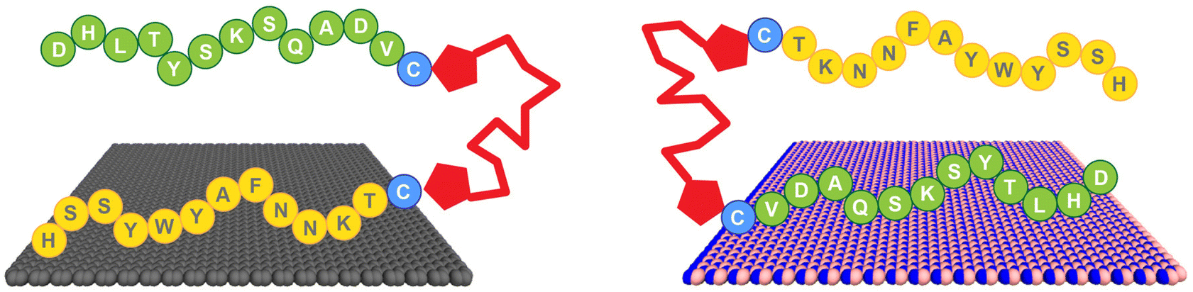 | ||
| Scheme 1 Regiospecific binding of the BEAM molecule onto graphene, via the P1 domain (left), and h-BN, via the BP7 domain (right). | ||
2. Experimental
2.1 Materials
Hydrochloric acid, sodium dodecyl sulfate (SDS), and sebacoyl chloride were acquired from Sigma. In addition, triethylamine (TEA), N,N-dimethylformamide (DMF), and ethyl ether were purchased from EMD Millipore. Dichloromethane (DCM) was obtained from Macron Fine Chemicals, while N-(2-aminoethyl)-maleimide hydrochloride was purchased from TCI. Ammonium persulfate was obtained from BDH chemicals. All peptides were commercially sourced from Genscript. The Au sensors used for QCM measurements were purchased from Nanoscience Instruments, while the Cu foil containing either graphene or h-BN were sourced from Grolltex. Lastly, the thermal release tape was acquired from Semiconductor Equipment Corporation. All chemicals were used as acquired without modification or purification. For all experiments and procedures, Ultrapure Mili Q water (18.2 M cm) was used.2.2 Synthesis of fatty acid spacer
The BEAM molecule was synthesized by adapting previously published methods (Fig. 1).21,22 For the fatty acid spacer, the final structure positions two terminal maleimide groups on a 10 carbon chain fatty acid. To achieve this, 50 mg of sebacoyl chloride was added to 10 mL of DCM, which was then cooled to 0–5 °C. In a separate vial, 146.6 mg of N-(2-aminoethyl)-maleimide hydrochloride and 144.3 μL of triethylamine were added to 10 mL of DCM. Next, the sebacoyl chloride solution was added to the second mixture dropwise, under a N2 atmosphere with constant stirring. Note that the molar ratio for the chloride![[thin space (1/6-em)]](https://www.rsc.org/images/entities/char_2009.gif) :maleimide:triethylamine was 1:5:4.95. The reaction was allowed to stir for 2 days, after which the DCM was evaporated. The obtained solid was mixed with a 0.1 M aqueous HCl solution for 20 min, followed by vacuum filtration. ESI-TOF mass spectrometry (ESI, Fig. S2†) was used to confirm the final product, which was termed F10F.
:maleimide:triethylamine was 1:5:4.95. The reaction was allowed to stir for 2 days, after which the DCM was evaporated. The obtained solid was mixed with a 0.1 M aqueous HCl solution for 20 min, followed by vacuum filtration. ESI-TOF mass spectrometry (ESI, Fig. S2†) was used to confirm the final product, which was termed F10F.
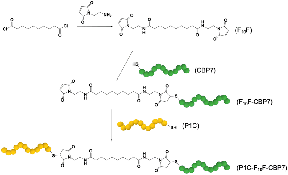 | ||
| Fig. 1 Synthesis of the BEAM molecule. The F10F fatty acid domain is prepared first, followed by the attachment of CBP7 and then by P1C in a second coupling step. | ||
2.3 Synthesis of the BEAM
For the synthesis of the BEAM molecule, the peptides were coupled sequentially using standard thiol/maleimide chemistries. Both the P1 and BP7 sequences were commercially produced (Genscript) with a cysteine attached at the appropriate terminus: C-terminus for P1 (termed P1C) and N-terminus for BP7 (termed CBP7). In this arrangement, once fully coupled, the BEAM would have a structure of P1C-F10F-CBP7. To begin the coupling process, the fatty acid was reacted with the CBP7 at a ratio of 5.21:1 (F10F:CBP7). For this, 39.7 mg of the synthesized F10F was dissolved in 6 mL DMF. In another vial, 25.0 mg of CBP7 was dissolved in 6 mL of DMF. The two solutions were then combined and allowed to stir for 3–4 days at room temperature. Afterwards, the solution was washed with diethyl ether to remove any unreacted F10F. The collected product, F10F-CBP7, was dissolved in water and then lyophilized for eventual purification by reverse phase HPLC and confirmation by MALDI-TOF mass spectrometry (ESI, Fig. S3†). Upon confirmation, coupling of the P1C at the exposed maleimide of the F10F-CBP7 was processed. To this end, 13.4 mg of F10F-CBP7 and 11.4 mg of P1C were co-dissolved in 3 mL of water, resulting in a 1:1 molar ratio of the two components. The reaction was then left to stir for 3 days at room temperature, after which, the mixture was lyophilized, purified by reverse phase HPLC, and verified using MALDI-TOF (ESI, Fig. S4†).
2.4 QCM experiments
All QCM measurements were conducted using a Q-Sense E4 instrument from Biolin Scientific at 22.5 °C with a flow rate of 150 μL min−1. To generate the appropriate sensor surfaces, Au QCM sensors were coated with a single layer of either graphene or h-BN using previous methods.23 Once the sensors were fabricated, they were cleaned via a 5 min UV ozone exposure to remove any non-specifically absorbed species. The sensors were then placed in the QCM instrument, to which water was flowed over the sensor surface for 30 min. This was followed by flowing of 2% SDS for 30 min, followed by a final 30 min flow of water. Once the surface was cleaned, water was first flowed over the sensors for 10 min to obtain a baseline for each measurement. Afterward, BEAM solutions (5.0–17.5 μg mL−1) were then flowed over the sensor surface for 30 min to observe the frequency change and dissipation energy. Each measurement was processed in triplicate from which the binding analysis was processed using a Langmuir fit of the data, as previously described.2,21,242.5 AFM measurements
A Veeco AFM (Dimension 3100) was used to conduct the AFM measurements in tapping mode. The sample preparation first started with the cleaving of the HOPG block with scotch tape to carefully peel off the outermost layer. An aqueous solution (500 μL) of the BEAM molecule (0.5 mg mL−1) was drop casted onto the clean freshly cleaved HOPG surface and allowed to dry for 15 min. The HOPG surface was then thoroughly washed with deionized water, dried with air, and left overnight for further drying.2.6 Molecular dynamics simulations
Replica-exchange with solute tempering molecular dynamics (REST-MD) simulations were performed to predict the most likely ensemble of surface-adsorbed conformations of the BEAM at the aqueous graphene and h-BN interfaces.25,26 The simulated system comprised one BEAM molecule, one planar (periodic) surface (either graphene or h-BN), ∼27000–30000 water molecules, and sufficient counter-ions to ensure overall charge neutrality of the simulation cell. The lateral dimensions of the periodic substrate were ∼8.9 × 8.9 nm and ∼9.0 × 9.5 nm for graphene and h-BN, respectively. The REST-MD simulations were based on 16 replicas and were run for a total of 50 ns (amounting to an aggregate of 0.8 μs per simulation). The GRAPPA27 and BoNi-CHARMM28 interfacial force-fields were used to describe inter-atomic interactions in the graphene and h-BN systems, respectively. Full details of the simulations and their analyses are provided in the ESI,† ‘Computational Details’.
3. Results and discussion
To generate the bifunctional BEAM molecule, a facile synthetic process was developed (Fig. 1), which can be generalized to incorporate different materials binding peptides. The synthesis began with production of the F10F fatty acid domain by replacing the two terminal chlorides present in sebeacoyl chloride with two maleimide groups. This would allow for bio-orthogonal coupling of the peptides via thiol maleimide coupling of the sequences at the fatty acid linker. Coupling of each peptide binding domain was done sequentially where the first peptide (CBP7) was mixed with the F10F, which was present in excess to limit double peptide coupling to a single fatty acid. Once the first coupling was complete, the second peptide (P1C) was added to the system to couple and generate the final construct. After each peptide coupling step, the materials were purified by HPLC and confirmed via MALDI-TOF mass spectrometry. Using this approach, a final molecule with a global structure of P1C-F10F-CBP7 was prepared, which is referred to as the BEAM.Once the BEAM molecule was synthesized, the binding affinity to both graphene and h-BN were studied by using QCM. This highly sensitive technique can measure small changes of mass adsorbed at a surface and can be used to determine the binding affinity of biomolecules onto a target material. Using standard methods, Au QCM sensors were coated with a single layer of either graphene or h-BN.23 During the binding measurements, aqueous solutions of the BEAM were flowed over the two different sensors ranging in concentration from 5.0–17.5 μg mL−1. The frequency change over time was measured where the inverted plot for BEAM binding at both graphene and h-BN are shown in Fig. 2a and b, respectively. As anticipated, clear changes in binding are evident as a function of BEAM concentration and the underlying sensor composition. Fitting of each binding surface can then be processed using the Langmuir isotherm, from which kobs values can be obtained. These kobs values can then be plotted as a function of BEAM concentration (Fig. 2c and d), from which a variety of kinetic parameters of binding can be determined via the line of best fit (e.g. slope = ka and y-intercept = kd). Using the ka and kd values, Keq can be determined and subsequently used to calculate the free energy of BEAM binding (ΔG) to both the graphene and h-BN surfaces.24,29
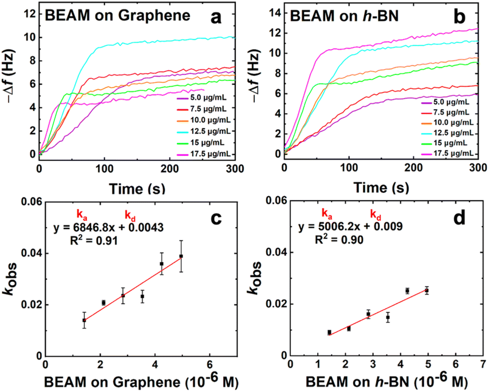 | ||
| Fig. 2 QCM analysis of the binding affinity of the BEAM molecule. Parts (a) and (b) show the inverted frequency change over time for a range of concentrations (5.0–17.5 μg mL−1) for BEAM binding to graphene and h-BN, respectively. Parts (c) and (d) present the linear relationship between kobs and BEAM concentration for (c) graphene and (d) h-BN. | ||
From the QCM binding analysis, a free energy of binding for the BEAM on graphene was determined to be −35.3 ± 1.9 kJ mol−1; however, when the same binding analysis was processed on h-BN, the ΔG value was calculated as −38.4 ± 1.2 kJ mol−1, as shown in Table 1. Based upon these values, this indicates that the BEAM molecule binds stronger to h-BN over graphene. Such results were quite surprising as this is different than what was previously reported for the parent peptides, BP7 and P1, both of which demonstrated greater affinity for graphene over h-BN (Table 1).12 Furthermore, these values also indicated that the BEAM bound either equivalently or stronger to both nanosheet surfaces as compared to the individual peptides, based upon the magnitude of the ΔG values. This suggests that changes in the biomolecular structure could be important in controlling the absolute affinity of the ligand to the material surface.
| h-BN | Graphene | |||
|---|---|---|---|---|
| Peptide | ΔG (kJ mol−1) | Maximum dissipation energy (u) | ΔG (kJ mol−1) | Maximum dissipation energy (u) |
| *P1 and BP7 data taken from ref. 12. BP7CF10 and F10CBP7 taken from ref. 19. | ||||
| P1CF10FCBP7 | −38.4 ± 1.2 | 1.88 | −35.3 ± 1.9 | 0.72 |
| P1 | −33.0 ± 2.2 | 0.14 | −35.6 ± 2.3 | 0.20 |
| BP7 | −29.5 ± 0.3 | 0.11 | −33.5 ± 3.9 | 0.27 |
| BP7CF10 | −30.2 ± 2.6 | 1.81 | — | — |
| F10CBP7 | −33.3 ± 1.6 | 0.36 | — | — |
It is important to note that while the difference in the ΔG values is somewhat small, prior studies have indicated that such differences can lead to significant variations in the coverage of the peptide on the target surface.11,29 In this prior work focused on comparing the fractional surface coverage (θ) of two peptides on the same surface (e.g. simultaneous binding of P1 and BP7 on graphene), the ratio of the equilibrium constants of binding for the two peptides is equivalent to the surface coverage ratio (e.g. θP1/θBP7) when the solution concentration of the two peptides is equal. Using the K values obtained previously for P1 and BP7 binding to graphene and h-BN, 2.4 and 4.1 times more P1 would be bound to graphene and h-BN, respectively, compared to the BP7 peptide. While a similar calculation cannot be performed using the BEAM (e.g. one peptide binding two different surfaces), this demonstrates that a significant degree of surface selectivity can be achieved based upon relatively small differences in ΔG values.
In addition to the frequency change, the dissipation energy was also monitored during the QCM study, which provided direct insight into the viscoelasticity of the BEAM overlayer generated at the nanosheet surface. Fig. 3 shows the dissipation energy over time as the BEAM molecule adsorbs to the graphene and h-BN surfaces. It is evident that as the BEAM molecule binds, the dissipation energy increases for all concentrations, suggesting varying degrees of viscoelasticity as a function of biomolecule concentration. The maximum dissipation energy measured for BEAM binding to graphene and h-BN is summarized in Table 1, revealing greater viscoelasticity for the BEAM bound to h-BN as compared to graphene. Such effects were somewhat surprising as the results presented suggested that a viscoelastic layer was generated on graphene. Previous studies of peptide overlayer formation on graphene demonstrated notably lower dissipation energy, indicating that a rigid monolayer structure was generated;21 however, when peptides modified with fatty acids are adsorbed to h-BN, significant viscoelasticity has been noted.14,19 The main difference likely arises due to the size of the biomolecule, where the BEAM is more than double the size of the individual P1 and BP7 peptides, and the multiple different binding domains present in the BEAM molecule. These two effects are likely to drive the emergence of a more viscoelastic interface, potentially through the formation of extended molecular structures away from the nanosheet surface.14,19 It is noted that these dissipation energy values are relatively high for binding at nanosheet surfaces, especially for the BEAM bound to h-BN, indicating that a highly viscoelastic interface was prepared on h-BN material.
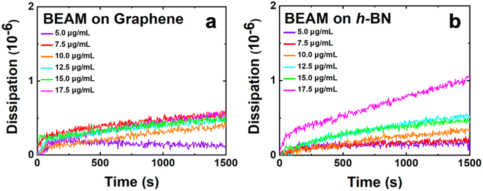 | ||
| Fig. 3 Dissipation energy analysis of the BEAM binding to (a) graphene and (b) h-BN. | ||
Additionally, AFM was used to image the overlayer structure of the BEAM molecule on the graphene surface. For this, highly oriented pyrolytic graphite (HOPG) was employed as the graphene surface for peptide overlayer formation; previous work has shown that peptide binding to HOPG is comparable to a single sheet of graphene.21 For the analysis, the BEAM solution was drop casted onto cleaved HOPG and allowed to sit for 15 min. Afterwards, the HOPG surface was rinsed with deionized water and dried prior to imaging in tapping mode. Fig. 4 shows the morphology of the BEAM peptide overlayer on HOPG, which demonstrated high coverage of the biomolecule on HOPG. Within the overlayer structure, small pores of various sizes and morphologies were noted. Such a porous morphology is consistent with overlayers of P1, both with and without fatty acids incorporated; however, the BEAM-based overlayer has considerably fewer pores that were generally smaller. The depth of the pores was determined and used to calculate the height of the peptide overlayer, which was ∼3.5 nm. Such a thickness was notably greater than those of the P1-based peptides; however, such an increase in thickness was anticipated based upon the larger size of the BEAM.
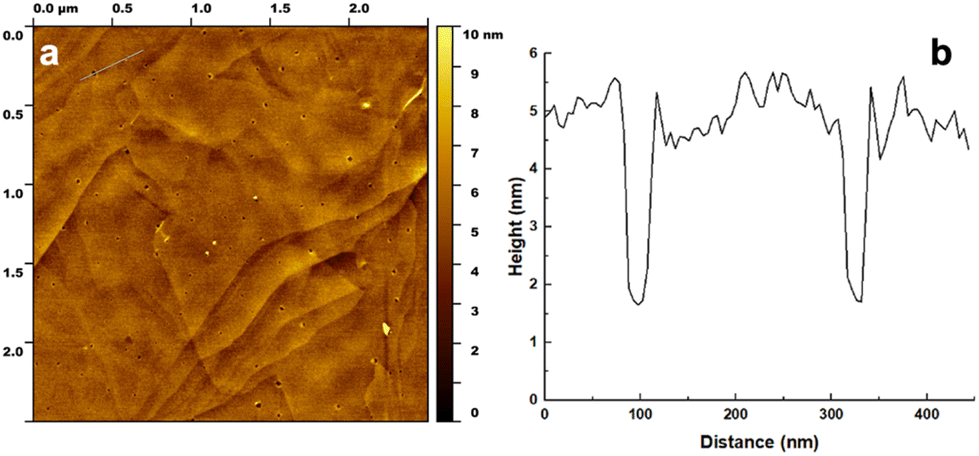 | ||
| Fig. 4 AFM analysis of the BEAM overlayer on HOPG at a concentration of 0.5 mg mL−1. Part (a) shows an area scan of the surface, while part (b) presents the height profile corresponding to the area indicated in the upper left section of part (a). | ||
In addition to the experimental analysis, computational studies were also conducted. Advanced sampling simulations using REST-MD simulations were used to predict the likely ensemble of adsorbed conformations of the BEAM molecule adsorbed at the aqueous interfaces of both graphene and h-BN. The amount of residue-surface contact was determined from the REST-MD simulations, summarized in Fig. 5. It is noted that a comparison of the absolute contact percentages across the two surfaces is not meaningful, given the differences in the two force-fields. On graphene, the P1 domain of the BEAM shows strong surface contact throughout most of the sequence, with a significant focus on the N-terminal half. The hydrophobic F10F linker also supported strong and consistent contact throughout, whereas the BP7 domain contact also supported a reasonably balanced distribution of contact sites along the length of the sequence. Comparison with data previously reported for the P1 and BP7 parent sequences12 indicated a spatial redistribution of the BEAM domain contact sites to the extremes of the BEAM ends (i.e., the N-terminus of the P1 domain and the C-terminus of the BP7 domain). On h-BN, the effects of the conjugation into the BEAM revealed an overall loss of contact for the P1 domain compared with the P1 parent, whereas for the BP7 domain, the degree of this change was less clear cut.
 | ||
| Fig. 5 Degree of residue-surface contact (given as a percentage of the total REST-MD simulation trajectory) for the BEAM molecule adsorbed at the aqueous graphene and h-BN interfaces. *Corresponding data for the P1 and BP7 parent peptides taken from ref. 12. | ||
However, not all residues bind with equal strength, meaning that the contact patterns alone do not capture the binding in its entirety.28,30 Using an enthalpic binding score as defined in previous work,31 which combines both the amino acid binding free energies on the two surfaces28,30 and the degree of contact, the binding specificity of each domain in the BEAM molecule can be estimated. For graphene, the P1 BEAM domain had a calculated binding score of −62.3 kJ mol−1 compared with a score of −58.9 kJ mol−1 for the BP7 BEAM domain, indicating materials specificity (i.e., P1 domain binding was preferred over BP7 domain binding on graphene). Similarly, the binding scores on h-BN for the BP7 and P1 BEAM domains were −20.7 and −15.6 kJ mol−1, respectively, indicating binding specificity of the BP7 domain over the P1 domain on its target h-BN surface. Again, direct comparison of the absolute values of these scores across the two materials is not meaningful due to the differences in the force-fields. Taken together, this enthalpic score analysis suggests that the two domains preferentially bind their anticipated target materials, achieving regioselective materials binding from the BEAM construct.
The entropic contributions to the overall binding can also be estimated, based on a clustering analysis, in which all frames in the REST-MD trajectory are grouped according to similarity in backbone structure (in which each group is a ‘cluster’). This analysis can be used to calculate the discrete entropy of the cluster distribution (number of clusters and their relative populations), denoted here as Sconf.11,30Sconf is a dimensionless quantity and can be correlated with the number of thermally accessible structures in the adsorbed state, and is calculated to be 3.2 and 3.8 for the BEAM adsorbed at the aqueous graphene and h-BN interfaces, respectively. The greater entropic contribution to binding for the BEAM on h-BN suggests an entropically-driven process, as compared to a more enthalpically-driven process for BEAM/graphene binding with a lower Sconf, which offers an explanation for the stronger binding free energy of the BEAM on h-BN versus graphene.
The proposed entropically-driven binding on h-BN, contrasted with the more enthalpically-driven binding on graphene, can be linked with the dissipation observations from the QCM-D experiments. Following previous studies, the dissipation energy (and thus the viscoelasticity of the adsorbed BEAM overlayer) is proposed to be associated with the number of upright states in the conformational ensemble, where regions of the BEAM molecule protrude away from the surface and into solution.14,19 Here, the BEAM adsorbed on h-BN supports a substantially enhanced population of upright states compared to the structures adsorbed to graphene, which can explain the relatively higher dissipation energy value observed for h-BN. To quantify this, the maximal value of the vertical molecule-surface distance was calculated over all frames in the two REST-MD trajectories, summarized in the histogram of Fig. 6a (full data shown in Fig. S5, ESI†). On h-BN, it is clear the BEAM adopts a greater fraction of surface-extended states, compared with the BEAM adsorbed to graphene. Example snapshots of the two trajectories provided in Fig. 6b and c reveal the more prone, horizontal contact mode on graphene compared with the upright state shown for the h-BN bound BEAM ligand. Additional views of these surface-bound states are provided in Fig. S6 of the ESI.†
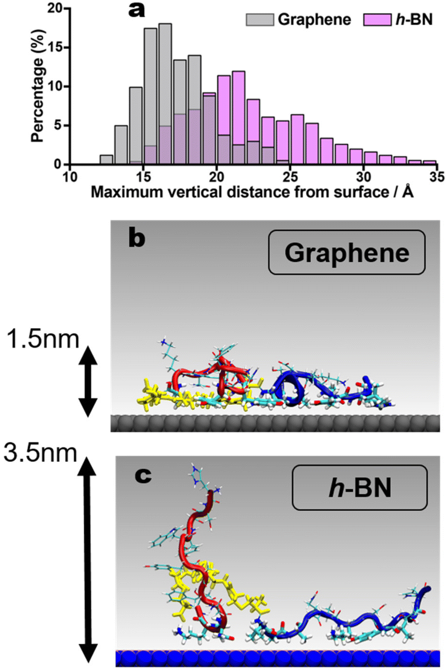 | ||
| Fig. 6 (a) Histogram of the maximal vertical molecule-surface distance of the BEAM in the surface adsorbed state at the aqueous graphene and h-BN interfaces. Example snapshots of the BEAM molecule adsorbed on (b) graphene and (c) h-BN, with the maximal vertical molecule-surface distance indicated. Color scheme: P1 in red, F10F linker in yellow, BP7 in blue. Water not shown for clarity. | ||
Another critical measure of success for these bioconjugate molecules to achieve regiospecific binding is the ability to keep the two materials-binding domains separate, such that their availability for binding to the target surfaces is maximized. This shifts the focus from the molecule-surface interactions to the intra-molecule interactions, which were quantified as summarized in Fig. 7 for the aqueous graphene interface. Fig. 7a shows that each residue in the P1 domain and BP7 domain feature little interaction with the rest of the molecule overall, for the case of adsorption on graphene (corresponding data for h-BN are provided in the ESI, Fig. S7†). The proportion of intra-molecule interactions is notably higher in the F10F linker region, which can in part be explained by the flexible nature of this alkane chain and its spatially compact methylene groups that allow for close methylene-methylene contact. These contact data presented in Fig. 7a were broken down into three contributions for each residue in Fig. 7b (analogous data shown in Fig. 7c for adsorption at the aqueous h-BN interface); intra-BEAM interactions with the P1 domain, with F10F, and with the BP7 domain. These clearly show that residues in the P1 domain chiefly interact either with residues in the P1 domain or in the linker domain, whereas the opposite is true for the residues in the BP7 domain. This limitation in the degree of inter-domain cross-talk when adsorbed at both materials interfaces indicate that the two materials-binding domains can remain spatially separated in the surface-adsorbed state to achieve regiospecific binding of the BEAM molecule to the target materials.
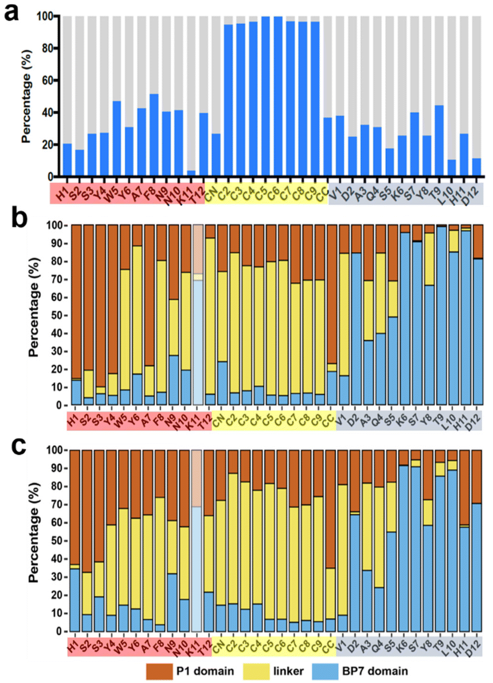 | ||
| Fig. 7 Summary of intra-BEAM interactions in the surface-adsorbed state at the aqueous interfaces. (a) The proportion of the trajectory for which a given residue has any interaction with the rest of the BEAM molecule, indicated by blue bars, on the graphene surface. The residues indicated on the ordinate are colored by domain (red for the P1 domain, yellow for F10F, blue for the BP7 domain). (b) Breakdown of each blue bar in panel (a) into interactions with the P1 domain (red bars), F10F (yellow bars) and BP7 domain (blue bars). Data for K11 are greyed out due to extremely low data volume. (c) Similar breakdown for BEAM adsorption at the h-BN interface. | ||
Finally, as a prelude to future investigations, MD simulations were used to explore the capability of the BEAM molecule to maintain a structurally-stable hetereostacked bilayer of a graphene nanosheet and an h-BN nanosheet in liquid water. In these simulations, a graphene nanosheet and an h-BN nanosheet, both of 7.2–7.5 nm diameter, were placed in a vertically stacked configuration, with a vertical gap of ∼1.5 nm. Five BEAM molecules were placed in this gap, and the cubic periodic cell (∼13 nm dimension) was filled with liquid water and subjected to MD simulation in the NVT ensemble at room temperature. The BEAM molecule was found to promote the stability of this heterostack arrangement. Stable configurations were found to remain so over 50 ns of production simulation; an example of a final configuration is provided in Fig. 8 (additional views shown in Fig. S8, ESI†).
 | ||
| Fig. 8 Snapshot shown in side view of an example heterostack of graphene and h-BN nanosheets (∼7.5 nm in diameter), stabilized by BEAM molecules in liquid water. Water molecules not shown for clarity. | ||
Based upon the differences in the ΔG values and the calculations of fractional surface coverage discussed above, a sequential approach to driving nanosheet assembly is proposed. In this situation, equivalent P1 and BP7 solution concentrations are present using the BEAM molecule, which displays one of each sequence as a nanosheet binding domain. When the BEAM is exposed to graphene, binding is anticipated where regiospecific adsorption of the P1 domain should occur (2.4 times more than BP7), thus presenting the BP7 domain preferentially to solution. Inclusion of h-BN sheets to this solution will drive binding of the secondary material, leading to heterostack formation. This capability is supported by the results of simulations shown in Fig. 8, confirming that the BEAM molecule can indeed facilitate heterostack assembly and stability.
4. Conclusions
Properties of a bifunctional biomolecule, referred to as a Biomolecular Exfoliant and Assembling Motif (BEAM), designed to achieve regiospecific binding capabilities for 2D materials were demonstrated and rationalized using an integration of experimental and molecular simulation approaches. The BEAM featured a graphene-binding domain containing the P1 sequence and an h-BN binding domain presenting the BP7 sequence, separated by a fatty acid chain; it was demonstrated to bind to aqueous interfaces of both materials, with stronger binding indicated for h-BN. The biomolecular overlayer on h-BN featured substantial viscoelasticity compared with graphene, which is attributed to the greater entropic contribution to adsorption on this surface. Advanced sampling molecular simulations indicate that the two peptide domains preferentially bound their respective target surfaces, and also highlight a clear lack of inter-domain interaction. These results show that ligands require significant complexity to achieve regiospecific affinity for two disparate materials, where biomolecular specificity could be instrumental to achieve such capabilities.Author contributions
The manuscript was written through contributions of all authors. All authors have given approval to the final version of the manuscript.Conflicts of interest
There are no conflicts to declare.Acknowledgements
This material is based upon work supported by the Air Force Office of Scientific Research, Grant FA9550-18-1-0329. TRW acknowledges computational resources provided by the National Computing Infrastructure (NCI), Canberra, and the Pawsey Supercomputing Centre, Perth, Australia, under the NCMAS scheme. Part of this work was also undertaken using the LIEF HPC-GPGPU Facility established with the assistance of LIEF Grant LE170100200, hosted at the University of Melbourne.References
- C. K. Yee, R. Jordan, A. Ulman, H. White, A. King, M. Rafailovich and J. Sokolov, Langmuir, 1999, 15, 3486–3491 CrossRef CAS.
- T. R. Walsh and M. R. Knecht, Chem. Rev., 2017, 117, 12641–12704 CrossRef CAS PubMed.
- T. R. Walsh and M. R. Knecht, Bioconjugate Chem., 2019, 30, 2727–2750 CrossRef CAS PubMed.
- R. Coppage, J. M. Slocik, B. D. Briggs, A. I. Frenkel, H. Heinz, R. R. Naik and M. R. Knecht, J. Am. Chem. Soc., 2011, 133, 12346–12349 CrossRef CAS PubMed.
- R. Coppage, J. M. Slocik, H. Ramezani-Dakhel, N. M. Bedford, H. Heinz, R. R. Naik and M. R. Knecht, J. Am. Chem. Soc., 2013, 135, 11048–11054 CrossRef CAS PubMed.
- Y. S. Nam, H. Park, A. P. Magyar, D. S. Yun, T. S. Pollom and A. M. Belcher, Nanoscale, 2012, 4, 3405–3409 RSC.
- W. Zhou, D. T. Schwartz and F. Baneyx, J. Am. Chem. Soc., 2010, 132, 4731–4738 CrossRef CAS PubMed.
- S. N. Kim, Z. Kuang, J. M. Slocik, S. E. Jones, Y. Cui, B. L. Farmer, M. C. McAlpine and R. R. Naik, J. Am. Chem. Soc., 2011, 133, 14480–14483 CrossRef CAS PubMed.
- C.-L. Chen and N. L. Rosi, Angew. Chem., Int. Ed., 2010, 49, 1924–1942 CrossRef CAS.
- Z. E. Hughes, M. A. Nguyen, J. Wang, Y. Liu, M. T. Swihart, M. Poloczek, P. I. Frazier, M. R. Knecht and T. R. Walsh, ACS Nano, 2021, 15, 18260–18269 CrossRef CAS PubMed.
- J. P. Palafox-Hernandez, Z. Tang, Z. E. Hughes, Y. Li, M. T. Swihart, P. N. Prasad, T. R. Walsh and M. R. Knecht, Chem. Mater., 2014, 26, 4960–4969 CrossRef CAS.
- N. Brljak, A. D. Parab, R. Rao, J. M. Slocik, R. R. Naik, M. R. Knecht and T. R. Walsh, Chem. Commun., 2020, 56, 8834–8837 RSC.
- Z. Tang, C.-K. Lim, J. P. Palafox-Hernandez, K. L. M. Drew, Y. Li, M. T. Swihart, P. N. Prasad, T. R. Walsh and M. R. Knecht, Nanoscale, 2015, 7, 13638–13645 RSC.
- N. Brljak, M. R. Knecht and T. R. Walsh, J. Phys. Chem. B, 2021, 125, 10621–10628 CrossRef CAS PubMed.
- C. R. So, Y. Hayamizu, H. Yazici, C. Gresswell, D. Khatayevich, C. Tamerler and M. Sarikaya, ACS Nano, 2012, 6, 1648–1656 CrossRef CAS PubMed.
- S. K. Mudedla, K. Balamurugan and V. Subramanian, J. Phys. Chem. C, 2016, 120, 28246–28260 CrossRef CAS.
- B. Akdim, R. Pachter, S. S. Kim, R. R. Naik, T. R. Walsh, S. Trohalaki, G. Hong, Z. Kuang and B. L. Farmer, ACS Appl. Mater. Interfaces, 2013, 5, 7470–7477 CrossRef CAS PubMed.
- H. Zhang, T. Yamazaki, C. Zhi and N. Hanagata, Nanoscale, 2012, 4, 6343–6350 RSC.
- N. Brljak, R. Jin, T. R. Walsh and M. R. Knecht, Nanoscale, 2021, 13, 5670–5678 RSC.
- M. A. Nguyen, Z. E. Hughes, Y. Liu, Y. Li, M. T. Swihart, M. R. Knecht and T. R. Walsh, J. Phys. Chem. C, 2018, 122, 11532–11542 CrossRef CAS.
- A. D. Parab, A. Budi, N. Brljak, M. R. Knecht and T. R. Walsh, Adv. Mater. Interfaces, 2021, 8, 2001659 CrossRef CAS.
- B. D. Briggs, J. P. Palafox-Hernandez, Y. Li, C.-K. Lim, T. J. Woehl, N. M. Bedford, S. Seifert, M. T. Swihart, P. N. Prasad, T. R. Walsh and M. R. Knecht, Phys. Chem. Chem. Phys., 2016, 18, 30845–30856 RSC.
- S. S. Kim, Z. Kuang, Y. H. Ngo, B. L. Farmer and R. R. Naik, ACS Appl. Mater. Interfaces, 2015, 7, 20447–20453 CrossRef CAS PubMed.
- C. Tamerler, E. E. Oren, M. Duman, E. Venkatasubramanian and M. Sarikaya, Langmuir, 2006, 22, 7712–7718 CrossRef CAS PubMed.
- T. Terakawa, T. Kameda and S. Takada, J. Comput. Chem., 2011, 32, 1228–1234 CrossRef CAS PubMed.
- L. B. Wright and T. R. Walsh, Phys. Chem. Chem. Phys., 2013, 15, 4715–4726 RSC.
- Z. E. Hughes, S. M. Tomásio and T. R. Walsh, Nanoscale, 2014, 6, 5438–5448 RSC.
- A. Budi and T. R. Walsh, Langmuir, 2019, 35, 16234–16243 CrossRef CAS PubMed.
- Z. Tang, J. P. Palafox-Hernandez, W.-C. Law, Z. E. Hughes, M. T. Swihart, P. N. Prasad, M. R. Knecht and T. R. Walsh, ACS Nano, 2013, 7, 9632–9646 CrossRef CAS PubMed.
- Z. E. Hughes and T. R. Walsh, J. Mater. Chem. B, 2015, 3, 3211–3221 RSC.
- N. M. Bedford, Z. E. Hughes, Z. Tang, Y. Li, B. D. Briggs, Y. Ren, M. T. Swihart, V. G. Petkov, R. R. Naik, M. R. Knecht and T. R. Walsh, J. Am. Chem. Soc., 2016, 138, 540–548 CrossRef CAS PubMed.
Footnotes |
| † Electronic supplementary information (ESI) available: Computational/experimental methodology, additional analysis and discussion. See DOI: https://doi.org/10.1039/d2nr03169h |
| ‡ These authors contributed equally. |
| This journal is © The Royal Society of Chemistry 2022 |