
Electrochemical atomic force microscopy of two-dimensional trinuclear ruthenium clusters molecular assembly and dynamics under redox state control†
Soichiro
Yoshimoto
 *a,
Jinnosuke
Kato
b,
Hiroki
Sakamoto
c,
Hironori
Minamoto
b,
Keita
Daicho
d,
Kazuki
Takamura
d,
Naoki
Shimomoto
d and
Masaaki
Abe
*d
*a,
Jinnosuke
Kato
b,
Hiroki
Sakamoto
c,
Hironori
Minamoto
b,
Keita
Daicho
d,
Kazuki
Takamura
d,
Naoki
Shimomoto
d and
Masaaki
Abe
*d
aInstitute of Industrial Nanomaterials, Kumamoto University, 2-39-1 Kurokami, Chuo-ku, Kumamoto 860-8555, Japan. E-mail: so-yoshi@kumamoto-u.ac.jp
bGraduate School of Science and Technology, Kumamoto University, 2-39-1 Kurokami, Chuo-ku, Kumamoto 860-8555, Japan
cDepartment of Applied Chemistry and Biochemistry, Faculty of Engineering Kumamoto University, 2-39-1 Kurokami, Chuo-ku, Kumamoto 860-8555, Japan
dGraduate School of Science, University of Hyogo, 3-2-1, Koto, Kamigori-cho, Ako-gun, Hyogo 678-1297, Japan. E-mail: mabe@sci.u-hyogo.ac.jp
First published on 9th June 2022
Abstract
Mixed-valence ruthenium trinuclear clusters containing dichloroacetates were synthesized, and the self-assembly of a single molecular adlayer composed of these clusters on a graphite surface was investigated by atomic force microscopy (AFM). AFM clearly revealed the dynamics of two-dimensional (2D) structure formation as well as the molecular characteristics of the adlayers at different electrochemical interfaces. The results verified that the design of metal complexes is important not only for redox chemistry but also for molecular assembly and nanoarchitecture construction.
The unique oxidation and spin states of metal complexes endow them with catalytic activities and novel electric, magnetic, and optical properties that are advantageous in a wide range of applications.1–7 For example, mixed-valence compounds are essential for molecular computing systems:8–10 that is, multiple redox states can minimize the molecular cross-sectional area needed to write and read electronic signals. Recently, self-assembly has been utilized as a key technique for nanosized architectures.11–13 For example, diruthenium complexes form one-dimensional coordinated molecular chains2,14,15 and paddle-wheel mixed valence complexes have been synthesized and characterized for high-density molecular memories.11,16 The mixed-valence triruthenium complex containing one CO and two solvent ligands such as tetrahydrofuran (THF) in terminal positions, [Ru3O(C2H5CO2)6(CO)(THF)2] (hereinafter referred to as complex 1), is an attractive precursor for supramolecular assemblies.17,18 Indeed, iron trinuclear sub-clusters can be utilized as building blocks for two-dimensional (2D) sheets.19 However, to exploit the triruthenium complex fully for 2D and thin film formation, it is necessary to understand the mechanisms of molecular assembly on surfaces and their electrochemical properties.
Scanning probe microscopy (SPM), including scanning tunneling microscopy (STM) and atomic force microscopy (AFM), is a powerful tool not only for understanding 2D molecular assembly and structural transformation,20–25 but also for three-dimensional mapping at the molecular scale.26 There are many reports on the characteristics of self-organized nanostructures and molecular assemblies on surfaces.21–24,26–28 High-speed AFM imaging has been useful for understanding the dynamics of biomolecules such as DNA,29 proteins,30–32 and cells33 in solution. However, in situ AFM imaging of metal complexes, especially at the electrochemical interface, remains limited because of the lack of suitable redox-active target molecules: that is, the drastic molecular arrangement changes occurring due to the control of self-assembly with redox reactions are unknown.
Herein, we report a newly designed ruthenium trinuclear Ru3O(CHCl2COO)6(bpy)3 (bpy = 4,4′-bipyridine; complex 2), which contains RuII, RuIII, and RuIII, to elucidate the function and properties of mixed-valence complexes with three ruthenium centers, especially the role of axial ligands. In addition to exhibiting high structural symmetry, 2 is expected to assemble through the π–π interactions among bpy moieties. We propose that this class of metal complexes can be used to understand the dynamics of molecular assembly through electrochemical redox control.
First, the UV-vis absorption spectra of complexes 1 and 2 were measured in methanol. In Fig. 1, a clear difference in absorption is observed in the 300–1200 nm wavelength range. Complex 1, a valence-localized {RuII, RuIII, RuIII} cluster, exhibits a characteristic absorption peak at 570 nm, which is assigned to the intra-cluster charge-transfer (ICCT) transition.17 In contrast to 1, the absorption peak of 2, a valence-averaged {RuII, RuIII, RuIII} cluster, shows a significantly red-shifted ICCT band at 880 nm in addition to a more intense cluster-to-ligand charge-transfer (CLCT) transition at 400 nm, which is similar to that observed for [Ru3O(CHCl2COO)6(pyridine)3].34
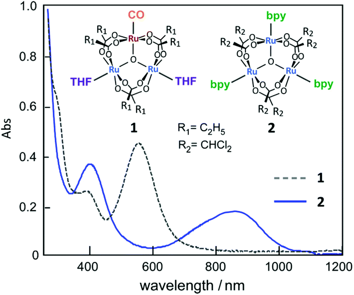 | ||
| Fig. 1 UV-vis absorption spectra of ca. 5 μM complexes 1 and 2 in methanol. | ||
To obtain information regarding the redox states of the thin films, their electrochemical properties were examined. Fig. 2 shows the typical cyclic voltammetry (CV) profiles of the 2-adsorbed HOPG electrode in 0.1 M HClO4. The 2-adsorbed HOPG electrode exhibits a redox couple at 0.72 V. As 2 originally has the oxidation state of {RuII, RuIII, RuIII} in one trinuclear cluster, the redox couple observed at 0.72 V can be assigned as a redox reaction of 2 from {RuII, RuIII, RuIII} to {RuIII, RuIII, RuIII}. No redox wave is observed in the potential region between 0 and 0.50 V. When the high-end potential is set higher than 1.20 V, the oxidative current gradually increases. The oxidative current involves partial oxidation of the HOPG surface. Fig. 2b shows that the oxidation peak current density and scan rate are well correlated, that is, the peak current is proportional to the scan rate. Judging from the CV profiles, the electric charge consumed by the oxidation peak was roughly estimated to be 1.10 ± 0.10 μC cm−2 for a 2-adsorbed HOPG electrode. If one-electron transfer reaction occurs in the one sub-cluster unit of 2 from {RuII, RuIII, RuIII} to {RuIII, RuIII, RuIII}, the surface excess is estimated to be 1.14 × 10⁻¹¹ mol cm−2. The 2-adsorbed HOPG electrode exhibits rapid electron transfer. Up to 0.20 V s−1, the peak separation is approximately 0 mV, indicating that the electron transfer reaction at the 2-deposited electrode occurs faster than that obtained at the Co/bis-terpyridine-modified Au(111) electrode.35 In the CV profile was recorded at a scan rate of 5.0 V s−1, the peak separation is within 60 mV, as shown in Fig. 2c. Furthermore, in the CV results obtained in 0.1 M H2SO4, a difference in the peak separation between HClO4 and H2SO4 is observed in the CV profile, as shown in Fig. 2c. Even at a scan rate of 5.0 V s−1, the peak separation is within 20 mV, indicating that the electron transfer reaction is very rapid and that anions influence the oxidation state, with {RuIII, RuIII, RuIII} as counter ions.
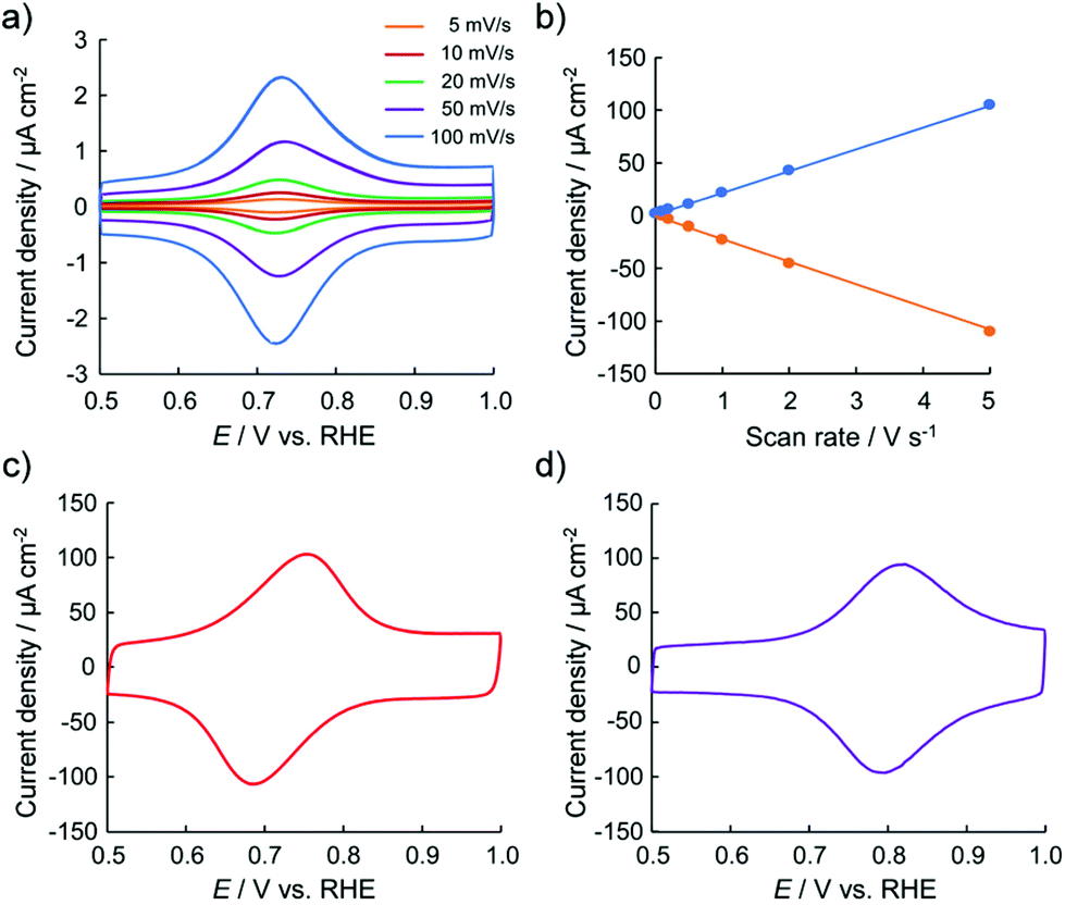 | ||
| Fig. 2 (a) Typical cyclic voltammograms of 2-deposited HOPG electrode in 0.1 M HClO4 recorded at various scan rates from 5 to 100 mV s−1 and (b) current-scan rate plot for the oxidation and reduction peak currents. CV profiles were obtained in (c) 0.1 M HClO4 and (d) 0.1 M H2SO4 recorded at 5.0 V s−1. | ||
The molecular assembly of 2 was investigated by AFM under ambient conditions. Fig. 3 shows a typical single-molecule 2 adlayer formed on HOPG. The large-scale AFM image in Fig. 3a depicts the boundary interface between the 2 adlayer and the HOPG surface. Characteristic domain formation is observed on the atomically flat HOPG terrace, and missing rows are evident in the domains. The typical domain size ranged from 25 to 50 nm in diameter. In addition, one-dimensional (1D) wires are apparent at the boundary edge as the region indicated by dotted circle. The AFM results confirm that the molecular assembly of 2 on HOPG is composed of banded 1D wire structures. According to the cross-sectional profile, the height of the 1D wires and domains is approximately 2 nm. The 2 nm height correlates with the molecular size of 2, and π–π interactions between the py rings of the bpy moieties enable molecules to self-assemble initially into wires. As shown in Fig. 3b, several highly ordered domains are formed in the higher-resolution AFM image. In these domains, stripes appear in at least three directions. The ordered domain is composed of straight strips with widths of approximately 5 nm. Considering the 2 nm tip radius of the cantilever, the actual distance between the wires is shorter, as indicated by the height differences between the 1D wires in Fig. 3a. To obtain more details on the stripes, we have attempted single crystallization and analysis of 2.
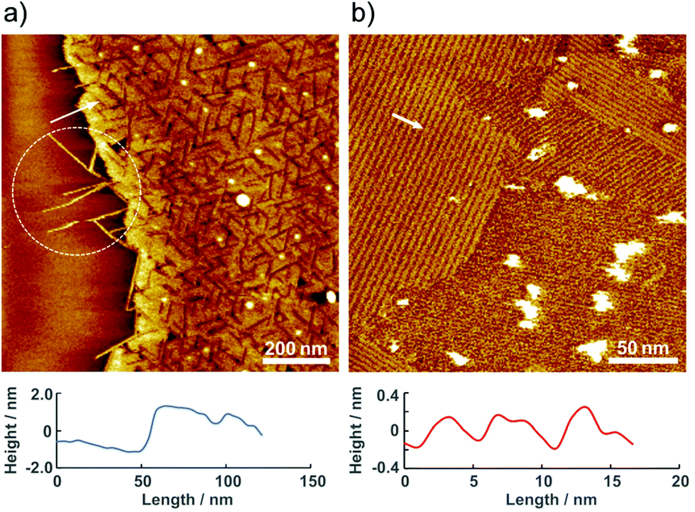 | ||
| Fig. 3 Typical AFM images of 2 adlayer on HOPG observed under ambient condition. (a) 1.0 × 1.0 μm2, (b) 0.25 × 0.25 μm2. The location of the cross-sectional profile is indicated by a white arrow and line. | ||
To understand the dynamics of the 2 adlayer at the electrochemical interface, EC-AFM was performed in 0.1 M HClO4. Fig. 4 shows the potential-dependent AFM images. At 0.60 V, which is nearly equal to the open-circuit potential (OCP), although the terrace is entirely covered with small spots, the structure formation observed under ambient conditions cannot be confirmed. At this potential, the oxidation state of the three ruthenium centers of 2 is considered to remain {RuII, RuIII, RuIII}, but the bpy ligands are protonated, bpyH+, by immersion in 0.1 M HClO4. The protonated 2 complexes can be mobilized easily. Therefore, organized stripe structures disappear and a random adlayer is formed when the adlayer contacts to the acidic solution. On the other hand, in the AFM image obtained at or near 1.0 V, large domains are formed not only on the terrace but also around the step of HOPG. The domain size diameter is approximately 200–500 nm with a height of 0.5 nm. Careful observation of one of the domains reveals that regularly striped structures are formed into circular islands along the direction indicated by the white arrows in Fig. 4c. The striped structure has a width of approximately 2 nm, and the height difference between stripes is approximately 0.4 nm. A regularly striped structure is formed at the potentials for the oxidation of 2, and the rate of formation is quite high. Indeed, when the potential switches to 0.60 V, the domains immediately disappeared on the terrace, and after the potential was stepped to 1.0 V, the domains are immediately formed on the terrace. Fig. 4d and e show in situ AFM images obtained at almost the same location. The lower part of Fig. 4d reveals several domains on the terrace. When the potential is stepped from 1.0 to 0.5 V, these domains immediately disappeared. Then, when the potential is switched from 0.5 to 1.0 V, many domains are immediately formed again. In addition, a clear change is observed near the step region between the dotted lines in the upper portion of Fig. 4d. Similarly, when the potential step is repeated during scanning, the formation and deformation of domains rapidly occurred on the terrace. Comparing Fig. 4d and e, it can be observed that the position and size of the domains changed, especially in the lower half of the scan area. Thus, the structural changes are reversible and occurred rapidly.
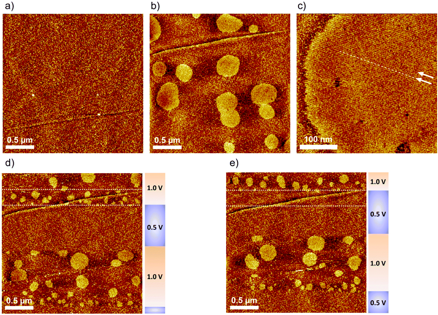 | ||
| Fig. 4 Typical EC-AFM images of 2 adlayer on HOPG in 0.1 M HClO4. Each image was obtained at (a) 0.60 V, (b and c) 1.00 V, (d and e) the electrode potential was kept at 0.50 V and/or 1.00 V by stepping potential during the scan. The scan direction was from bottom to top. | ||
In situ AFM was also performed in 0.1 M H2SO4, and the results were compared to the AFM images taken in HClO4. As shown in Fig. 5a, the 2 adlayer is composed of random and disordered structures in the reduced form at 0.60 V, which is similar to that obtained in Fig. 4a. When the potential is switched to 1.0 V, the oxidized form, a subtle change is observed on the terrace, that is, some aggregated islands are formed near the steps, as indicated by the white arrows. In 0.1 M H2SO4, no ordered stripes are observed, suggesting that anions play an important role in the formation of the stripe domain. Indeed, counter ions are necessary to satisfy the charge balance electrostatically because the oxidation state of 2 is {RuIII, RuIII, RuIII}. With 0.1 M H2SO4 condition, the dominant species of anions is not SO42−, but rather HSO4− which is a structurally asymmetric. In contrast to HSO4−, ClO4− has a symmetrical structure. Based on the AFM images, although we do not understand where such anions are in the stripes, the structural symmetry of the anions would affect the incorporation of 2 and anions. The structural difference in the oxidized form between ClO4− and HSO4− also reflects the difference in the CV profiles recorded at a higher scan rate of 5.0 V s−1.
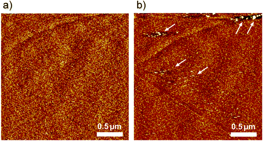 | ||
| Fig. 5 In situ AFM images (2.5 × 2.5 μm2) of 2 adlayer on HOPG in 0.1 M H2SO4 observed at (a) 0.60 V and (b) 1.0 V vs. RHE. | ||
In conclusion, we designed a new trinuclear Ru complex and found that the complex-modified HOPG electrode exhibited a reversible and rapid electrochemical response in both 0.1 M HClO4 and H2SO4. Highly ordered adlayers on HOPG were formed by the self-assembly of 2 molecules. In situ AFM imaging in acidic solutions revealed drastic changes in the progression of the molecular self-assembly of the 2 adlayer and the dynamics at the electrochemical interfaces. Remarkable stripe formation is dependent on the anions in the electrolyte solution. Trinuclear Ru complexes can be used as functional building blocks for assembling nanoarchitectures via electrochemical redox reactions.
Author contributions
S. Y.: conceptualization; methodology; EC-STM investigation; data curation; funding acquisition; project administration; supervision; writing – original draft & editing. J. K. & H. S.: AFM/EC-AFM investigation; data curation; H. M., K. D., K. T., & N. S.: synthesis, characterization and data curation of 2. M.A.: funding acquisition; supervision; writing–review & editing. All authors discussed the results and commented on the manuscript.Conflicts of interest
There are no conflicts to declare.Acknowledgements
This work was supported by JSPS KAKENHI [grant numbers JP16H06514 (Coordination Asymmetry), 19H02560, and 19K22115] and the IINa Collaboration Research Project of the Institute of Industrial Nanomaterials, Kumamoto University.Notes and references
- H. Kitagawa and T. Mitani, Coord. Chem. Rev., 1999, 190–192, 1169–1184 CrossRef CAS.
- M. Mikuriya, D. Yoshioka and M. Honda, Coord. Chem. Rev., 2006, 250, 2194–2211 CrossRef CAS.
- J. Zheng, Z. Lu, K. Wu, G.-H. Ning and D. Li, Chem. Rev., 2020, 120, 9675–9742 CrossRef CAS PubMed.
- L. Bai, Z. Duan, X. Wen, R. Si, Q. Zhang and J. Guan, ACS Catal., 2019, 9, 9897–9904 CrossRef CAS.
- J. Yu, Q. He, G.-M. Yang, W. Zhou, Z.-P. Shao and M. Ni, ACS Catal., 2019, 9, 9973–10011 CrossRef CAS.
- T. Kawashima, T. Takao and H. Suzuki, Angew. Chem., Int. Ed., 2006, 45, 7615–7618 CrossRef CAS PubMed.
- T. Kaneko, T. Takao and H. Suzuki, Angew. Chem., Int. Ed., 2013, 52, 11884–11887 CrossRef CAS PubMed.
- S. B. Braun-Sand and O. Wiest, J. Phys. Chem. A, 2003, 107, 285–291 CrossRef CAS.
- Z. H. Li and T. P. Fehlner, Inorg. Chem., 2003, 42, 5715–5721 CrossRef CAS PubMed.
- J. Jiao, G. J. Long, L. Rebbouh, F. Grandjean, A. M. Beatty and T. P. Fehlner, J. Am. Chem. Soc., 2005, 127, 17819–17831 CrossRef CAS PubMed.
- R. Kuwahara, S. Fujikawa, K. Kuroiwa and N. Kimizuka, J. Am. Chem. Soc., 2012, 134, 1192–1199 CrossRef CAS PubMed.
- H. Nishihara, Coordination, Chem. Lett., 2014, 43, 388–395 CrossRef CAS.
- K. Ariga and M. Shionoya, Bull. Chem. Soc. Jpn., 2021, 94, 839–859 CrossRef CAS.
- D. Olea, R. González-Prieto, J. L. Priego, M. C. Barral, P. J. de Pablo, M. R. Torres, J. Gómez-Herrero, R. Jimánez-Aparicio and F. Zamora, Chem. Commun., 2007, 1591–1593 RSC.
- L. Welte, R. González-Prieto, D. Olea, M. R. Torres, J. L. Priego, R. Jiménez-Aparicio, J. Gómez-Herrero and F. Zamora, ACS Nano, 2008, 2, 2051–2056 CrossRef CAS PubMed.
- S. Yoshimoto, K. Sakata, R. Kuwahara, K. Kuroiwa, N. Kimizuka and M. Kunitake, J. Phys. Chem. C, 2012, 116, 17729–17733 CrossRef CAS.
- A. Inatomi, M. Abe and Y. Hisaeda, Eur. J. Inorg. Chem., 2009, 32, 4830–4836 CrossRef.
- M. Abe, A. Inatomi and Y. Hisaeda, Dalton Trans., 2011, 40, 2289–2298 RSC.
- D. Bara, C. Wilson, M. Mörtel, M. M. Khusniyarov, S.-L. Ling, B. Slater, S. Sproules and R. S. Forgan, J. Am. Chem. Soc., 2019, 141, 8346–8357 CrossRef CAS PubMed.
- S. Yoshimoto, Bull. Chem. Soc. Jpn., 2006, 79, 1167–1190 CrossRef CAS.
- J. A. A. W. Elemans, I. De Cat, H. Xu and S. De Feyter, Chem. Soc. Rev., 2009, 38, 722–736 RSC.
- S. Mohnani and D. Bonifazi, Coord. Chem. Rev., 2010, 254, 2342–2362 CrossRef CAS.
- K. Tahara, S. Lei, J. Adisoejoso, S. De Feyter and Y. Tobe, Chem. Commun., 2010, 46, 8507–8525 RSC.
- W. Auwärter, D. Écija, F. Klappenberger and J. V. Barth, Nat. Chem., 2015, 7, 105–120 CrossRef.
- S. Yoshimoto, T. Kawamoto, T. Okawara, Y. Hisaeda and M. Abe, Langmuir, 2016, 32, 13635–13639 CrossRef CAS.
- T. Fukuma and R. Garcia, ACS Nano, 2018, 12, 11785–11797 CrossRef CAS PubMed.
- V. Palermo, A. Liscio, M. Palma, M. Surin, R. Lazzaronic and P. Samorì, Chem. Commun., 2007, 3326–3337 RSC.
- S. Datta, Y. Kato, S. Higashiharaguchi, K. Aratsu, A. Isobe, T. Saito, D. D. Prabhu, Y. Kitamoto, M. J. Hollamby, A. J. Smith, R. Dalgliesh, N. Mahmoudi, L. Pesce, C. Perego, G. M. Pavan and S. Yagai, Nature, 2020, 583, 400–405 CrossRef CAS PubMed.
- T. Brouns, H. De Keersmaecker, S. F. Konrad, N. Kodera, T. Ando, J. Lipfert, S. De Feyter and W. Vanderlinden, ACS Nano, 2018, 12, 11907–11916 CrossRef CAS PubMed.
- A. Rajendran, M. Endo and H. Sugiyama, Chem. Rev., 2014, 114, 1493–1520 CrossRef CAS PubMed.
- T. Ueno, K. Niwase, D. Tsubokawa, K. Kikuchi, N. Takai, T. Furuta, R. Kawano and T. Uchihashi, Nanoscale, 2020, 12, 8166–8173 RSC.
- B. Maity, Z. Li, K. Niwase, C. Ganser, T. Furuta, T. Uchihashi, D. Lu and T. Ueno, Phys. Chem. Chem. Phys., 2020, 22, 18562–18572 RSC.
- M. Li, D. Dang, N. Xi, Y. Wang and L. Liu, Nanoscale, 2017, 9, 17643–17666 RSC.
- A. Inatomi, M. Abe and Y. Hisaeda, Aust. J. Chem., 2012, 65, 1599–1607 CrossRef CAS.
- S. Yoshimoto and K. Nishiyama, J. Inorg. Organomet. Polym. Mater., 2013, 23, 233–238 CrossRef CAS.
Footnote |
| † Electronic supplementary information (ESI) available. See DOI: https://doi.org/10.1039/d2nr01666d |
| This journal is © The Royal Society of Chemistry 2022 |