
Regulating the electronic and magnetic properties of 1T′-ReS2 by fabricating nanoribbons and transition-metal doping: a theoretical study†
Simei
Li
a,
Shuqing
Zhang
b and
Ruiqi
Zhao
 *a
*a
aHenan Key Laboratory of Materials on Deep-Earth Engineering, School of Materials Science and Engineering, Henan Polytechnic University, Henan 454003, China. E-mail: zhaoruiqi@hpu.edu.cn
bInstitute of Information Photonics Technology, Faculty of Science, Beijing University of Technology, Beijing 100124, China
First published on 11th May 2022
Abstract
Monolayer 1T′-type rhenium disulphide (1T′-ReS2) has promising applications in spintronic devices due to its unique electronic properties induced by inversion loss in the crystal structure. A prerequisite of such applications is introducing magnetism in 1T′-ReS2. Here, we studied the electronic and magnetic properties of zigzag 1T′-ReS2 nanoribbons (1T′-ReS2-NRs) and further tuned their magnetic properties by transition-metal doping. Our results show that 1T′-ReS2-NRs exhibit tunable electronic properties ranging from indirect bandgap to direct bandgap to metallic properties. Among the energy-favoured S-terminated 1T′-ReS2-NRs, only one exhibits robust magnetic properties. The magnetic properties of the other two nanoribbons can be effectively tuned by doping with certain transition metals. Among the configurations of TM-doped 1T′-ReS2-NRs, only those with TM atoms introduced at the edge sites are energy-favoured. The magnetic properties of TM-doped 1T′-ReS2-NRs are mainly contributed by the TM atom, the Re and S atoms at the edges of the nanoribbons. Besides this, the bulk Re and S atoms close to the TM atom also contribute positively to the magnetism and such contributions become weaker as the atoms are farther from the TM atom. These results provide deep insights into the modulations of the electronic and magnetic properties of 1T′-ReS2 at the atomic scale, and thus should pave an effective path for fabricating 2D materials for spintronic devices.
1 Introduction
Since the successful exfoliation of graphene in 2004, two-dimensional (2D) materials have attracted great attention due to their intriguing electronic properties.1–4 Among various 2D materials,5,6 transition-metal dichalcogenides (TMDs) exhibit various promising applications in many fields, including optoelectronic devices,7 gas sensing materials8 and electronic devices.9 Unfortunately, the electrical properties of TMDs present a high dependence on the number of layers,10 strain11 and bandwidth,12 which greatly inhibits their applications. Very recently, a new member of the TMD family, 1T′-rhenium disulphide (1T′-ReS2), has initiated research interests due to its robust properties induced by in-plane inversion loss.13,14Monolayer 1T′-ReS2 is a semiconductor with a direct bandgap of 1.43 eV.15 Unlike other TMDs, 1T′-ReS2 contains twisted octahedra with triclinic symmetry.14,16 The Re–Re atoms in monolayer 1T′-ReS2 form rhombus with an angle of ∼119.8° between the a and b axes.14,17,18 The diamond-shaped chains induce in-plane anisotropy and interlayer decoupling effects, both of which lead to the unique electronical properties in 1T′-ReS2. Therefore, 1T′-ReS2 has a wide range of applications in infrared sensing,19 strain sensors,20,21 photodetectors22 and battery anode materials.23,24 The robust electronic properties of monolayer 1T′-ReS2 also make it a promising candidate in quantum information devices. A prerequisite for this application is the introduction of magnetism in 1T′-ReS2.
Various approaches have been developed to tune the electrical and magnetic properties of 2D materials. As experimental scientists and theorists have reported, property modulations can be achieved by edge reconstruction,25 heteroatom doping,26 vacancy defects,27 and stress.11,28 Among the various methods, one efficient approach is to fabricate nanoribbons due to the prevalent presence of asymmetric spin states at the edges.29,30 Nanoribbons can be constructed along two perpendicular directions, resulting in two typical types of nanoribbons terminated with zigzag and armchair edges, respectively.31 Li and co-workers reported that in molybdenum disulphide nanoribbons (MoS2-NRs), zigzag MoS2-NRs exhibit width-independent metallic properties, whereas armchair MoS2-NRs are semiconductors with the band gap varies along with the width. More interestingly, zigzag MoS2-NRs exhibit magnetic properties while no magnetism exists in armchair MoS2-NRs.29 Furthermore, the ferromagnetism of 1T′-MoS2-NRs can be stabilized by edge reconstruction.30 Another efficient way to regulate magnetism is to introduce transition metals (TMs) into 2D materials.32–34 For example, Pan and co-worker reported that TM-doping in armchair MoS2-NRs can tune the electronic and magnetic properties, and the magnetism is mainly concentrated on the TM atoms and Mo atoms at the edge.32 The electronic properties of TM-doped ReS2 nanosheets have been used as electrocatalysts.33,34 It has been reported that compared with pristine materials, Mn-doped ReS2 nanosheets exhibit low overpotential, significantly enhanced durability, high specific capacity, excellent cycling performance and rate capability,33 and Mo-doped ReS2 nanosheets present better intrinsic conductivity and optimized catalytic activity.34 However, to our knowledge, no work has been reported so far to tune the properties of the new member 1T′-ReS2 by the fabrication of nanoribbons and TM doping.
It has been reported that zigzag MoS2 nanoribbons have an energetic advantage over their armchair counterparts,29 and a zigzag 1T′-ReS2 sheet has been observed in the grain boundary zone by experimental researchers very recently.13 Therefore, we constructed pristine and TM-doped zigzag 1T′-ReS2NRs. The electronic and magnetic properties of these nanoribbons were investigated by first-principles calculations. Our results show that the electronic and magnetic properties of 1T′-ReS2NRs are completely different from those of monolayer 1T′-ReS2. Unlike the monolayer films, pristine nanoribbons exhibit tunable electronic properties varying from semiconducting to metallic nanoribbons, and magnetism can be introduced in some nanoribbons. Robust magnetism can be further introduced into 1T′-ReS2NRs by doping certain transition metals. The magnetism in TM-doped 1T′-ReS2NRs is mainly contributed by the TM atoms and the Re and S atoms at the edges. The spin charge density shows that the bulk Re and S atoms close to the TM atom also contribute little to the magnetism. Our findings not only provide atomic-scale insights into the understanding of the intrinsic origins of introducing magnetism in 1T′-ReS2NRs, but also pave an efficient path for tuning the properties of 2D materials, and thus may be helpful in facilitating their applications in nanodevices and spintronics.
2 Models and simulations
The relaxed monolayer 1T′-ReS2 is shown in Fig. 1a. The lattice parameters are a = 6.53 and b = 6.42 Å, respectively, agreeing well with the experimental (a = 6.45 and b = 6.39 Å)35 and theoretical (a = 6.51 and b = 6.41 Å)22 ones. In this work, zigzag 1T′-ReS2NRs were constructed along three high symmetric directions comprising [100], [010] and [110] (Fig. 1a). For TM-doped 1T′-ReS2NRs, TM atoms were introduced at different sites by directly replacing Re atoms. The obtained nanoribbons are labelled a, b and c, respectively. Considering the binary compositions in bulk 1T′-ReS2, the constructed nanoribbons can be terminated with S and Re (highlighted with pink and blue, respectively). Therefore, a total of six nanoribbons were constructed (see the top and side views in Fig. 1b for details). The obtained nanoribbons were indentified with two components comprising cutting directions and edge types. For example, the S-terminated 1T′-ReS2 nanoribbon cut along the [100] direction is named a-NRs-S. The widths of nanoribbons cut along the a, b, and c directions fall in the range of 24.84–27.89 Å (see Fig. S1† for detailed information). The supercell of all nanoribbons is 6.42 × 51.23 × 22.00 Å3. The vacuum along the y direction falls in the range of 23.34–26.39 Å due to the small width difference along the a, b, and c directions. The vacuum along the z direction is 18.62 Å (see Fig. S2† for detailed information). We notice that Li and co-worker used a vacuum of 10 Å to study the stability and electronic and magnetic properties of MoS2 nanoribbons.29 Therefore, both the nanoribbon width and the vacuum are large enough to ensure negligible interactions between opposing edges and adjacent nanoribbons. More details of the six 1T′-ReS2NRs and the vacuum are shown in Fig. S1 and S2,† respectively.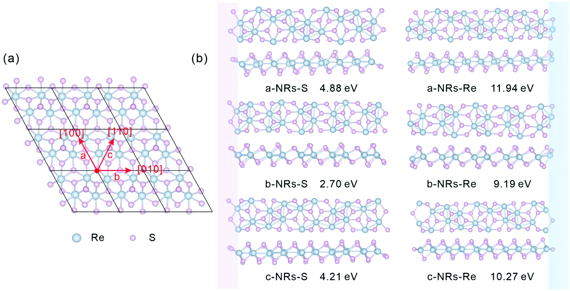 | ||
| Fig. 1 (a) Top view of monolayer 1T′-ReS2. Three typical directions ([100], [010] and [110], which are defined as a, b and c, respectively) along which to construct 1T′-ReS2 nanoribbons are also presented. (b) Top and side views of the optimized 1T′-ReS2 nanoribbons (1T′-ReS2NRs). The pink and blue rectangles highlight the edges terminated with S and Re atoms, respectively. The formation energy of each nanoribbon is also presented under each ribbon. | ||
All geometry optimization, partial density of states (PDOS), Bader charge and spin charge density calculations were performed using VASP software based on the pseudopotential approach and the projector augmented wave (PAW) method.36–38 The exchange–correlation interactions are described by the Perdew–Burke–Ernzerhof (PBE) generalized gradient approximation (GGA) functionals.39 A cut-off energy of 550 eV was used in all simulations. The k-Point densities of 9 × 1 × 1 and 9 × 1 × 3 were used for structure optimization and PDOS calculation, respectively. The convergence criteria for energy and force were set as 10−6 eV and 0.01 eV Å−1, respectively.
The formation energy, Ef, is well used to identify the stabilities of clusters,40 nanoribbons and their edges,31,41,42 and solid solutions.43,44 The formation energies of the undoped and TM-doped 1T′-ReS2NRs, denoted as Ef_pure and Ef_TM, respectively, can be calculated as:
| Ef\_pure = ENRs − nμ1T′-ReS2 | (1) |
| Ef\_TM = ETM-NRs − ENRs − μTM + μRe | (2) |
3 Results and discussion
3.1 Stability and electronic and magnetic properties of pristine 1T′-ReS2NRs
The relaxed geometry of each 1T′-ReS2NR seen from the top and side views is shown in Fig. 1b. The obtained formation energy of each nanoribbon is also presented (Fig. 1b). For the S-terminated 1T′-ReS2NRs cut along the a, b and c directions, the formation energies are 4.88, 2.70 and 4.21 eV, respectively. For the Re-terminated 1T′-ReS2NRs, their formation energies are 11.94, 9.19 and 10.27 eV, respectively. The results clearly show that the formation energy of S-terminated nanoribbons is 6–7 eV lower than that of Re-terminated counterparts. Among the three nanoribbons terminated with the same S edge, the one cut along the b direction is the most stable.We now turn to discuss the electronic properties of bulk 1T′-ReS2 and its derived nanoribbons. The DFT results show that monolayer 1T′-ReS2 is a semiconductor with a direct band gap of 1.43 eV (see Fig. S2† for detailed band structures and PDOS), agreeing well with the result (1.43 eV) reported by Wu and co-workers.15 The PDOS of monolayer 1T′-ReS2 exhibits symmetrical spin-up and spin-down electron distributions (Fig. S2†), indicating the absence of magnetism in the 1T′-ReS2 films. The detailed band structures, bandgaps and PDOS of the six constructed zigzag 1T′-ReS2NRs are shown in Fig. 2. For the S-terminated nanoribbons, it can be observed that they are semiconductors and the gaps are reduced compared with monolayer 1T′-ReS2, and the nanoribbon of a-NRs-S is a semiconductor with an indirect gap of 0.38 eV. For the Re-terminated nanoribbons, the nanoribbons cut along the a and b directions are both semiconducting with indirect bandgaps, while the one cut along the c direction is metallic. The PDOS distributions of all nanoribbons are also quite different from that of monolayer 1T′-ReS2. For the nanoribbons of a-NRs-S, b-NRs-S, and c-NRs-Re, the total DOS contributed by specific atoms exhibits a symmetric feature (Fig. 2a, b and f) while for the other three naoribbons, c-NRs-S, a-NRs-Re and b-NRs-Re, the PDOS shows asymmetric distributions (Fig. 2c, d and e). The asymmetric PDOS shows that magnetic properties can be introduced and tuned by fabricating nanoribbons.
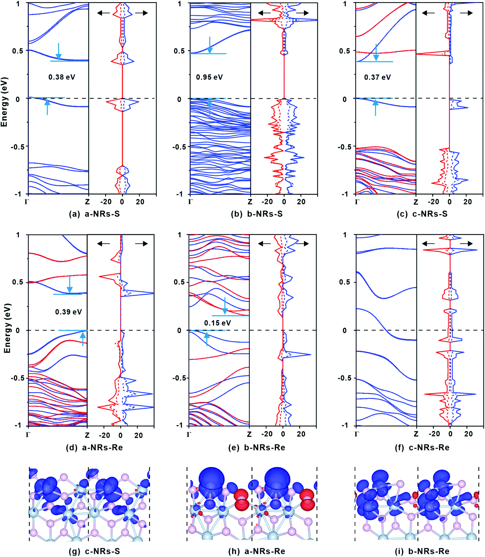 | ||
| Fig. 2 (a–f) Spin-up (blue) and spin-down (red) electronic band structures and PDOS contributed by specific atoms of 1T′-ReS2NRs. The gaps between the valence band maximum (VBM) and the conduction band minimum (CBM) are also listed. The solid and dashed lines in the PDOS represent the electron density distributions of Re and S, respectively. The Fermi level is also presented with dashed lines. (g–i) Spin charge density distributions in c-NRs-S, a-NRs-Re and b-NRs-Re. The isosurface level in the spin charge density is 0.002 eV Å−3. Blue and red stand for positive and negative (defined as ρspin-up − ρspin-down) electron density, respectively. | ||
To further explore the origin of the induced large difference in the magnetic properties of 1T′-ReS2NRs, the detailed PDOS contributed by the specific atoms of the six 1T′-ReS2NRs is shown in Fig. S3.† It can be observed that the PDOS in a-NRs-S, b-NRs-S and c-NRs-Re are distributed symmetrically, agreeing well with the total DOS shown in Fig. 2a, b and f. The PDOS contributed by specific atoms in nanoribbons such as c-NRs-S, a-NRs-Re and b-NRs-Re exhibit an asymmetric distribution, mainly concentrated on the d orbital of Re and the p orbital of S (Fig. S3c, d, and e†). Therefore, the magnetism of c-NRs-S, a-NRs-Re and b-NRs-Re is mainly contributed by the distributions of electrons on the 5d orbital of Re and the 3p orbital of S. The spin charge densities of c-NRs-S, a-NRs-Re and b-NRs-Re are shown in Fig. 2g–i, respectively. It clearly shows that the magnetism is mainly concentrated on the Re and S atoms at the edge. This effect can be attributed to edge states induced by unpaired electrons. Similar contributions have also been reported in other 2D materials such as graphene,45,46 β-P films,41and h-BN.31,42 The edge states also provide an efficient way to tune the properties of 2D materials by constructing nanoribbons. Besides this, the apparently asymmetric PDOS in the d orbitals of Re (see Fig. 2g–i and Fig. S3c, d, and e†) also suggests a promising way to tune the magnetism of 1T′-ReS2 nanoribbons by introducing transition metals. Therefore, in the following section, we turn to explore the possibility of tuning the magnetism of two stable 1T′-ReS2NRs, a-NRs-S and b-NRs-S, by introducing transition metals.
3.2 Stabilities and local magnetism distributions of TM-doped a-NRs-S and b-NRs-S
We start by figuring out the energetically favourable doping sites. Three transition metals, Cr, Mn and Co, were used and ten positions of nanoribbons of a-NRs-S and b-NRs-S were considered (see the schematic structures shown in Fig. 3a). The formation energies are summarized in Fig. 3b. It can be observed that for the Cr-, Mn- and Co-doped nanoribbons, irrespective of a-NRs-S or b-NRs-S, the configurations with TM atoms introduced at two edge sites (sites 1 and 2) are much more stable and site 1 is the most energy-favoured one. For the two configurations where the TM is introduced in the edge site, there is a small difference in stability. Such a small difference may be attributed to the in-plane anisotropy of the two nanoribbons induced by the inherent symmetry in 1T′-ReS2. A similar energy-favoured doping preference in the edge sites has also been reported in armchair MoS2NRs.30 The same doping site preference has also been reported in zigzag MoS2NRs with the GGA+U functional.47 Therefore, site 1 was selected as the doping position to study the stabilities and magnetic properties of TM-doped a-NRs-S and b-NRs-S in the next section.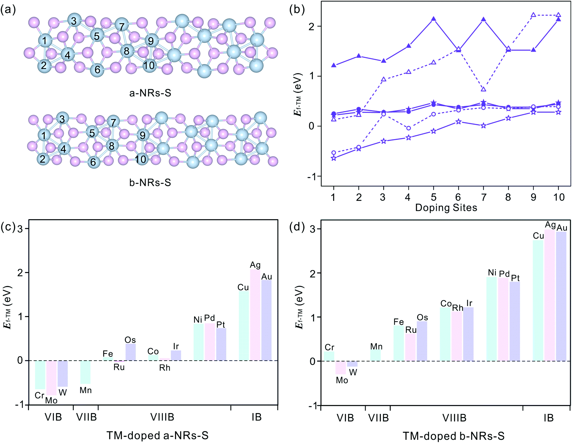 | ||
| Fig. 3 (a) Schematic structures of a-NRs-S and b-NRs-S with doping sites labelled with Arabic numbers. (b) Formation energies of Cr- (star), Mn- (circle), and Co- (triangle) doped configurations with sites shown in panel a (a-NRs-S, solid symbols and b-NRs-S, hollow symbols). (c) and (d) Formation energies of the TM-doped nanoribbons of a-NRs-S (c) and b-NRs-S (d). The doping metals are also presented in panels c and d. The data with TMs in the same row are shown in identical colors. | ||
The introduction of Cr, Mn and Co also induces distortion due to the radius difference between the host and guest ions. To study the detailed distortions in a-NRs-S and b-NRs-S, the local structure and variations of geometries with Cr, Mn, and Co are shown in Fig. S4† and Table S2.† It can be observed that the edge S atoms move inward to the TM atoms after doping (see the bond lengths of d6 and d7 in Table S2†). The shapes of the local polyhedra are well preserved, except for small changes after the introduction of TM atoms. A similar motion has been reported in 3d TM-doped armchair MoS2NRs.47
Sixteen transition metals are considered to study the magnetism modulations by introducing TM atoms at site 1 in the nanoribbons of a-NRs-S and b-NRs-S. The formation energies of TM-doped a-NRs-S and b-NRs-S are shown in Fig. 3c and d, respectively. The lower the formation energy, the higher the stability.44 For TM-doped a-NRs-S (Fig. 3c), it can be observed that most TMs can stabilize the nanoribbons, especially those that fall into the VIB and VIIB groups. For TM-doped b-NRs-S (Fig. 3d), only those with TMs falling in the VIB group can stabilize the nanoribbons. The value of Ef increases almost linearly as the TM column changes from left to right. For the two nanoribbons doped with TM in the same column, the difference in Ef falls within a small range of 0.10–0.52 eV. Among all the configurations, nanoribbons doped with TMs falling in the VIB and VIIB groups are more stable than those doped with other TMs. The TMs falling in the VIB and VIIB groups are close to the substituted Re in the periodic table of elements. For the nanoribbons doped with metals in the IB group, they are unstable due to high formation energy (Fig. 3c and d).
3.3 Magnetic properties of TM-doped a-NRs-S and b-NRs-S
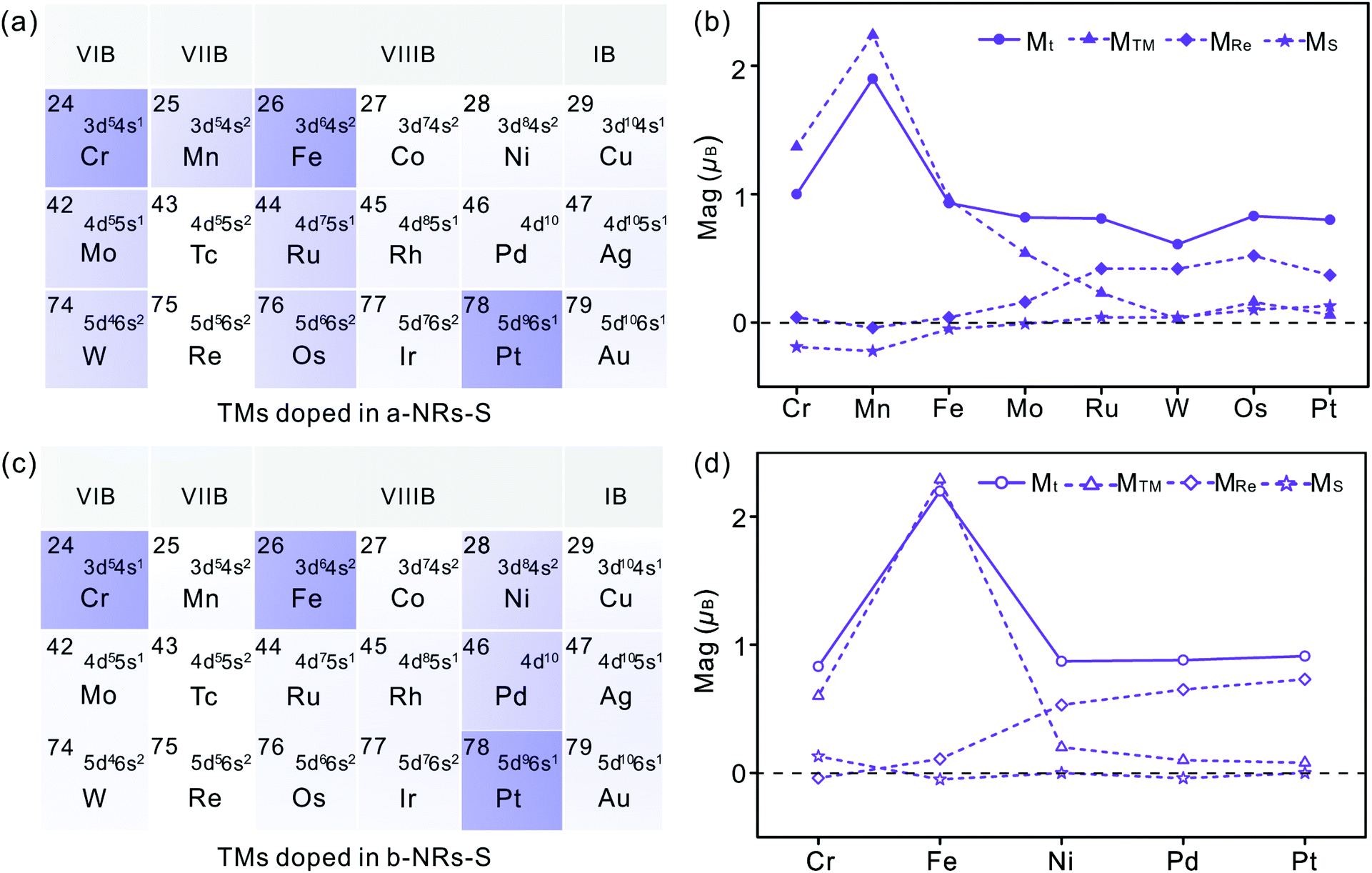 | ||
| Fig. 4 TMs doped in a-NRs-S (a) and b-NRs-S (b). The TMs doped in nanoribbons are highlighted with shades. The atoms that can introduce magnetism are highlighted with light purple and those can introduce magnetism in both ribbons are highlighted with dark purple. (c) and (d) Magnetism of TM-doped nanoribbons. The solid and dashed lines are presented as guidance for the total magnetism and magnetism contributed by specific elements. Solid and hollow symbols represent the magnetism of TM-doped a-NRs-S (b) and b-NRs-S (d). The circle, triangle, diamond and star represent the magnetic moments of total (Mt), TM atoms (MTM), edge Re (MRe) and edge S (MS), respectively. | ||
There is no magnetism in both pristine nanoribbons of a-NRs-S and b-NRs-S. The origin of induced magnetism in the TM-doped nanoribbons must be closely related to the doping atoms. Besides this, the atoms on the edge may also have positive contributions, as presented in c-NRs-S, a-NRs-Re and b-NRs-Re (Fig. 2g–i). The detailed magnetism contributed by TM atoms and edge atoms are also shown in Fig. 4b and d (see the data shown with dashed lines), respectively. The similar variation trends between the total magnetism, Mt, and the magnetism contributed by the TM atom, MTM are similar, indicating that the magnetism in the doped nanoribbons is mainly contributed by the TM atoms. The edge atoms Re and S also induce magnetism in the doped nanoribbons. For TM-doped a-NRs-S, the magnetism contributed by the edge Re in the Cr-, Mn-, Fe- and Mo-doped nanoribbons is smaller than that in the Ru-, W-, Os- and Pt-doped nanoribbons (see the data presented with solid diamonds in Fig. 4b). For TM-doped b-NRs-S, the magnetism contributed by the edge Re in the Cr- and Fe-doped nanoribbons is smaller than that in the Ni-, Pd- and Pt-doped nanoribbons (see the data presented with hollow diamonds in Fig. 4d). Generally, the contributions induced by the edge S are smaller than those induced by the edge Re and some negative contributions appear (Fig. 4b and d). The negative magnetism indicates that the distributions of electrons on other spin states contribute to the magnetism.
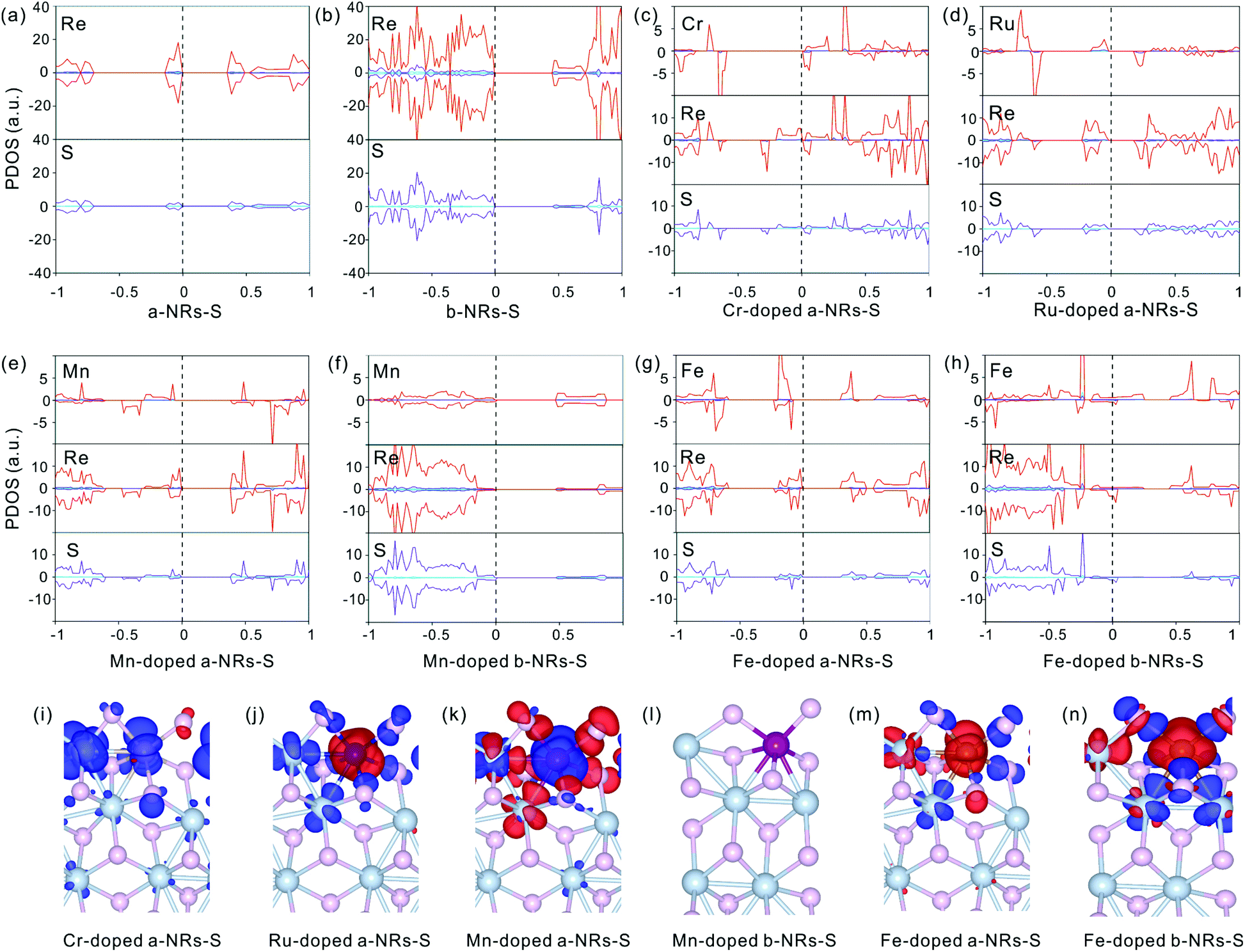 | ||
| Fig. 5 PDOS (a–h) distributions of specific atoms and spin charge density (i–n) in pristine and TM-doped nanoribbons of a-NRs-S and b-NRs-S. The blue, purple and red lines in the PDOS represent the orbitals of s, p and d, respectively. The isosurface level in the spin charge density is 0.002 eV Å−3. Blue and red stand for positive and negative (defined as ρspin-up − ρspin-down) electron density, respectively. | ||
The symmetrical electron density distributions in the orbitals of s, p, and d (see Fig. 5a and b) indicate the absence of magnetism in two pristine a-NRs-S and b-NRs-S, agreeing well with the conclusions obtained from the total DOS distributions (see Fig. 2a and b). For the TM-doped nanoribbons with magnetism, the reason for inducing magnetism is very complicated. In both nanoribbons, irrespective of a-NRs-S or b-NRs-S, the asymmetric distributions on the d orbitals of the TM atoms are more pronounced (see Fig. 5c, d, e, g and h). Besides this, the d orbitals of Re and the p orbitals of S also show some asymmetric distributions. The PDOS distributions are quite different in nanoribbons doped with different TM atoms (see the Cr-, Ru-, Mn- and Fe-doped a-NRs-S in Fig. 5c, d, e and g). When TM atoms are introduced into the new systems, the asymmetric distributions of electrons are easy on half-filled d orbitals. TMs with fully filled d electrons, Cu, Ag and Au can also illustrate this effect of valence electron distributions on d orbitals. No magnetism is introduced in both nanoribbons doped with Cu, Ag, and Au (see Fig. 4a and c). Hu and co-workers also reported that magnetic moments can be induced by Cr and Fe in monolayer ReS2.48
Besides the influences from electron distributions on the d orbital of TM atoms, the magnetism is also affected by the electron redistribution of the atoms surrounding the TM. To present the electron redistribution more clearly, the Bader charge analyses of the TM atom and atoms around it are presented in Fig. S9.† From Fig. S9† it can be observed that the atoms around the TM atom exhibit different charge distributions. As reported in armchair MoS2 nanoribbons,32 the coupling between the TM atom and its surrounding atoms may also contribute to the magnetism of TM-doped 1T′-ReS2NRs. For example, in a-NRs-S and b-NRs-S doped with the same TM, the magnetism is completely different. Taking Mn- and Fe-doped nanoribbons as examples, the magnetism of Mn-doped a-NRs-S is 1.90μB while b-NRs-S has no magnetism, for the Fe-doped nanoribbons, the magnetism of b-NRs-S (2.20μB, Fig. 4d) is 1.27μB higher than that of a-NRs-S (0.93μB, Fig. 4b). The apparent difference in the PDOS distributions of Mn-/Fe- doped a-NRs-S (Fig. 5e and g) and b-NRs-S (Fig. 5f and h) can also well reflect the large difference in magnetism.
Spin charge density distributions can intuitively illustrate the net distributions (defined as ρspin–up − ρspin-down) of electrons on each atom. The spin charge density distributions of some TM-doped nanoribbons are shown in Fig. 5i–n. It can be observed that there is a clear net electron distribution for Cr-, Ru- and Mn-doped a-NRs-S, while no distribution is observed in Mn-doped a-NRs-S, indicating the absence of magnetism in Mn-doped a-NRs-S, and the spin charge is mainly located on the edge atoms. Besides this, the spin-charge density distribution observed on the bulk Re is also far from the TM atom (see panels i, j, k, m, and n in Fig. 5).
From the above analyses, it can be concluded that both fabricating nanoribbons and TM doping can effectively tune the electronic properties of 1T′-ReS2 from a direct bandgap semiconductor to an indirect bandgap semiconductor to a metallic film. Some TM atoms can induce robust magnetism in 1T′-ReS2 nanoribbons. The work performed on MoS2 showed that various factors such as the types of TM atoms, the doping sites, and the nanoribbons fabricated along different directions can affect both electronic and magnetic properties.32,47,49,50 The edge reconstructions,31,41 underlying substrates42 and chemical potential difference31 also induce difference in stabilities and redistributions of electron density, and thus should lead to differences in magnetic properties. Besides this, both the functionals and the splitting between the doped TM atom and the edge atoms also have a great influence on the magnetic properties.32,47 To further facilitate the application of 1T′-ReS2 in spintronic devices, great efforts should be devoted to this complicated system.
4 Conclusion
In summary, the electronic structures and magnetic properties of pristine and TM-doped 1T′-ReS2-NRs were systematically studied by density functional theory. The following results were obtained:(1) The electronic structures and magnetic properties of 1T′-ReS2 can be effectively tuned by fabricating nanoribbons and TM doping.
(2) The electronic properties of monolayer 1T′-ReS2 can be tuned from a semiconductor with a direct band gap to an indirect semiconductor to metallic materials by fabricating nanoribbons.
(3) Among all 1T′-ReS2 nanoribbons, the nanoribbons terminated with S are more energetically favourable than their counterparts terminated with Re and the magnetism of S-terminated ReS2-NRs can be effectively tuned by introducing transition metals.
(4) The magnetism of TM-doped 1T′-ReS2 nanoribbons is mainly contributed by the TM atom, and the edge Re and S atoms. The bulk Re and S atoms close to the TM atom also exhibit a positive contributions to the magnetism and such contributions become weaker as the atoms are farther from the TM atom.
The above results not only provide deep insights into the understanding of the interesting electronic and magnetic properties of 1T′-ReS2 NRs at the atomic scale, but also create efficient ways of tuning the properties of 1T′-ReS2 and other 2D materials, and thus should provide helpful information in facilitating their applications in spintronic devices.
Author contributions
Simei Li: investigation, visualization, validation, and writing original version. Shuqing Zhang: partial data curation and visualization. Ruiqi Zhao: conceptualization, methodology, resources, supervision, formal analysis, and writing – review and editing.Conflicts of interest
The authors declare no competing financial interest.Acknowledgements
This work was supported by the Fundamental Research Funds for the Universities of Henan Province (no. NSFRF180326), the Innovation Scientists and Technicians Troop Construction Projects of Henan Province (no. CXTD2017089), the Open Fund of Key Laboratory for Intelligent Nano Materials and Devices of the Ministry of Education (no. NJ2020003), and the High-Performance Grid Computing Platform of Henan Polytechnic University.References
- K. S. Novoselov, A. K. Geim, S. V. Morozov, D. Jiang, Y. Zhang, S. V. Dubonos, I. V. Grigorieva and A. A. Firsov, Science, 2004, 306(5696), 666–669 CrossRef CAS PubMed.
- Y. Gong, J. Lin, X. Wang, G. Shi, S. Lei, Z. Lin, X. Zou, G. Ye, R. Vajtai, B. I. Yakobson, H. Terrones, M. Terrones, B. K. Tay, J. Lou, S. T. Pantelides, Z. Liu, W. Zhou and P. Ajayan, Nat. Mater., 2014, 13(12), 1135–1142 CrossRef CAS PubMed.
- L. Wang, X. Xu, L. Zhang, R. Qiao, M. Wu, Z. Wang, S. Zhang, J. Liang, Z. Zhang, Z. Zhang, W. Chen, X. Xie, J. Zong, Y. Shan, Y. Guo, M. Willinger, H. Wu, Q. Li, W. Wang, P. Gao, S. Wu, Y. Zhang, Y. Jiang, D. Yu, E. Wang, X. Bai, Z. Wang, F. Ding and K. Liu, Nature, 2019, 570(7759), 91–95 CrossRef CAS PubMed.
- M. Li, Y. Shi, C. Cheng, L. Lu, Y. Lin, H. Tang, M. Tsai, C. Chu, K. Wei, J. He, W. Chang, K. Suenaga and L. Li, Science, 2015, 349(6247), 524–528 CrossRef CAS PubMed.
- H. Li and R. Zhao, Revealing dissociation of ammonia borane and its subsequent nucleation on the Ru(0001) surface by density functional theoretical simulations, Phys. Chem. Chem. Phys., 2022, 24, 12226–12235 RSC.
- H. Li, H. Zhu and R. Zhao, Revealing initial nucleation of hexagonal boron nitride on Ru(0001) and Rh(111) surfaces by density functional theoretical simulations, New J. Chem., 2022 10.1039/D2NJ01702D.
- W. Choi, N. Choudhary, G. H. Han, J. Park, D. Akinwande and Y. H. Lee, Mater. Today, 2017, 20(3), 116–130 CrossRef CAS.
- E. Lee, Y. S. Yoon and D. Kim, ACS Sens., 2018, 3, 2045–2060 CrossRef CAS PubMed.
- M. R. Islam, N. Kang, U. Bhanu, H. P. Paudel, M. Erementchouk, L. Tetard, M. N. Leuenberger and S. I. Khondaker, Nanoscale, 2014, 6(17), 10033–10039 RSC.
- P. Yang, Z. Zhang, M. Sun, F. Lin, T. Cheng, J. Shi, C. Xie, Y. Shi, S. Jiang, Y. Huan, P. Liu, F. Ding, C. Xiong, D. Xie and Y. Zhang, ACS Nano, 2019, 13(3), 3649–3658 CrossRef CAS PubMed.
- Z. Liu, M. Amani, S. Najmaei, Q. Xu, X. Zou, W. Zhou, T. Yu, C. Qiu, A. G. Birdwell, F. J. Crowne, R. Vajtai, B. I. Yakobson, Z. Xia, M. Dubey, P. M. Ajayan and J. Lou, Nat. Commun., 2014, 5, 5246 CrossRef PubMed.
- G. Eda, H. Yamaguchi, D. Voiry, T. Fujita, M. Chen and M. Chhowalla, Nano Lett., 2011, 11(12), 5111–5116 CrossRef CAS PubMed.
- S. Wang, Y. Yu, S. Zhang, S. Zhang, H. Xu, X. Zou and J. Zhang, Matter, 2020, 3(6), 2108–2123 CrossRef.
- Y. Lin, H. Komsa, C. Yeh, T. Björkman, Z. Liang, C. Ho, Y. Huang, P. Chiu, A. V. Krasheninnikov and K. Suenaga, ACS Nano, 2015, 9(11), 11249–11257 CrossRef CAS PubMed.
- S. Tongay, H. Sahin, C. Ko, A. Luce, W. Fan, K. Liu, J. Zhou, Y. Huang, C. Ho, J. Yan, D. F. Ogletree, S. Aloni, J. Ji, S. Li, J. Li, F. M. Peeters and J. Wu, Nat. Commun., 2014, 5, 3252 CrossRef PubMed.
- W. Wen, Y. Zhu, X. Liu, H. Hsu, Z. Fei, Y. Chen, X. Wang, M. Zhang, K. Lin, F. Huang, Y. Wang, Y. Huang, C. Ho, P. Tan, C. Jin and L. Xie, Small, 2017, 13(12), 1603788 CrossRef PubMed.
- D. A. Chenet, O. B. Aslan, P. Y. Huang, C. Fan, A. M. van der Zande, T. F. Heinz and J. C. Hone, Nano Lett., 2015, 15(9), 5667–5672 CrossRef CAS PubMed.
- X. Chen, B. Lei, Y. Zhu, J. Zhou, M. Gao, Z. Liu, W. Ji and W. Zhou, ACS Mater. Lett., 2021, 3(10), 1513–1520 CrossRef CAS.
- H. Zhao, J. Wu, H. Zhong, Q. Guo, X. Wang, F. Xia, L. Yang, P. Tan and H. Wang, Nano Res., 2015, 8(11), 3651–3661 CrossRef CAS.
- S. Das, S. Prasad, B. Chakraborty, B. Jariwala, S. Shradha, D. Muthu, A. Bhattacharya, U. V. Waghmare and A. K. Sood, Nanoscale, 2021, 13(2), 1248–1256 RSC.
- S. Yu, H. Zhu, K. Eshun, C. Shi, M. Zeng and Q. Li, Appl. Phys. Lett., 2016, 108, 191901 CrossRef.
- Z. G. Yu, Y. Cai and Y. W. Zhang, Sci. Rep., 2015, 5, 13783 CrossRef PubMed.
- L. Wang, Z. Sofer, J. Luxa, S. David, A. Ambrosi and M. Pumera, Electrochem. Commun., 2016, 63, 39–43 CrossRef.
- B. Chen, H. Li, H. Liu, X. Wang, F. Xie, Y. Deng, W. Hu, K. Davey, N. Zhao and S. Z. Qiao, Adv. Energy Mater., 2019, 9, 1901146 CrossRef.
- H. Ma, W. Zhao, S. Yuan, H. Ren, H. Zhu, H. Ma, F. Ding and W. Guo, Mater. Today Phys., 2021, 19, 100411 CrossRef CAS.
- M. Luo and Y. E. Xu, Optik, 2018, 158, 291–296 CrossRef CAS.
- W. Xu, W. Xu, F. Zhan, A. Laref, R. Wang and X. Wu, J. Electron. Mater., 2019, 48, 3763–3776 CrossRef CAS.
- H. J. Conley, B. Wang, J. I. Ziegler, R. F. Haglund, S. T. Pantelides and K. I. Bolotin, Nano Lett., 2013, 13(8), 3626–3630 CrossRef CAS PubMed.
- Y. Li, Z. Zhou, S. Zhang and Z. Chen, J. Am. Chem. Soc., 2008, 130(49), 16739–16744 CrossRef CAS PubMed.
- K. Chen, J. Deng, X. Ding, J. Sun, S. Yang and J. Z. Liu, J. Am. Chem. Soc., 2018, 140(47), 16206–16212 CrossRef CAS PubMed.
- R. Zhao, J. Gao, Z. Liu and F. Ding, Nanoscale, 2015, 7(21), 9723–9730 RSC.
- J. Pan, R. Wang, X. Zhou, J. Zhong, X. Xu and J. Hu, Phys. Chem. Chem. Phys., 2017, 19, 24594–24604 RSC.
- J. Wang, J. He, G. O. Odunmbaku, S. Zhao, Q. Gou, G. Han, C. Xu, T. Frauenheim and M. Li, Chem. Eng. J., 2021, 414, 128811 CrossRef CAS.
- J. Xu, C. Fang, Z. Zhu, J. Wang, B. Yu and J. Zhang, Nanoscale, 2020, 12(32), 17045–17052 RSC.
- C. H. Ho, Y. S. Huang, P. C. Liao and K. K. Tiong, J. Phys. Chem. Solids, 1999, 60(11), 1797–1804 CrossRef CAS.
- G. Kresse and J. Furthmüller, Comput. Mater. Sci., 1996, 6(1), 15–50 CrossRef CAS.
- G. Kresse and J. Furthmüller, Phys. Rev. B: Condens. Matter Mater. Phys., 1996, 54(16), 11169–11186 CrossRef CAS PubMed.
- G. Kresse and J. Hafner, J. Non-Cryst. Solids, 1993, 47(1), 558–561 CAS.
- S. Rekhi, S. K. Saxena, R. Ahuja, B. Johansson and J. Hu, J. Mater. Sci., 2001, 36(19), 4719–4721 CrossRef CAS.
- H. Zhu, J. Zhu, Z. Zhang and R. Zhao, J. Phys. Chem. C, 2021, 125(48), 26542–26551 CrossRef CAS.
- R. Zhao, X. Wei, H. Zhu, S. Li and H. Li, Phys. Chem. Chem. Phys., 2022, 24(5), 3348–3356 RSC.
- R. Zhao, F. Li, Z. Liu, Z. Liu and F. Ding, Phys. Chem. Chem. Phys., 2015, 17, 29327–29334 RSC.
- R. Zhao, L. Zhang, G. Fan, Y. Chen, G. Huang, H. Zhang, J. Zhu and X. Guan, Cem. Concr. Res., 2021, 144, 106420 CrossRef CAS.
- R. Zhao, L. Zhang, B. Guo, Y. Chen, G. Fan, Z. Jin, X. Guan and J. Zhu, Composites, Part B, 2021, 222(14), 109092 CrossRef CAS.
- T. Wassmann, A. P. Seitsonen, A. M. Saitta, M. Lazzeri and F. Mauri, Phys. Rev. Lett., 2008, 101(9), 096402 CrossRef PubMed.
- O. V. Yazyev and M. I. Katsnelson, Phys. Rev. Lett., 2008, 100(4), 047209 CrossRef PubMed.
- X. Tian, L. Liu, Y. Du, J. Gu, J. Xu and B. Yakobson, Phys. Chem. Chem. Phys., 2015, 17(3), 1831–1836 RSC.
- J. Pan, X. Zhou, J. Zhong and J. Hu, Phys. Lett. A, 2019, 383(11), 125883 CrossRef CAS.
- X. Sun, K. Yang and Z. Li, Phys. Status Solidi RRL, 2021, 2100611 Search PubMed.
- J. Hyun and M. Kim, IEEE Trans. Magn., 2019, 55(2), 1–4 Search PubMed.
Footnote |
| † Electronic supplementary information (ESI) available: Width and vacuum of zigzag 1T′-ReS2 nanoribbons; lattice parameters and the calculated chemical potentials of the transition metals; band structures and the density of states of monolayer 1T′-ReS2; local structures of a-NRs-S and b-NRs-S before/after doping the TM atoms of Cr, Mo and Co; the partial density of states contributed by specific elements in 1T′-ReS2 nanoribbons; the partial density of states in Mo-, W-, Os-, and Pt-doped a-NRs-S; the partial density of states in pristine, Ni-, Pd-, Co-, Rh-, Ir-, Cu-, Ag-, and Au-doped a-NRs-S; and the partial density of states in Cr-, Ni-, Pd- and Pt-doped b-NRs-S; 9. Bader charge analysis of atoms around doping sites in pristine and TM-doped a-NRs-S. See DOI: https://doi.org/10.1039/d2nr00488g |
| This journal is © The Royal Society of Chemistry 2022 |