Binder-free mechanochemical metal–organic framework nanocrystal coatings†
Rijia
Lin
a,
Yuqi
Yao
a,
Muhammad Yazid Bin
Zulkifli
ab,
Xuemei
Li
 a,
Shuai
Gao
 a,
Wengang
Huang
 a,
Simon
Smart
ac,
Miaoqiang
Lyu
ac,
Lianzhou
Wang
 ad,
Vicki
Chen
a and
Jingwei
Hou
 *a
*a
aSchool of Chemical Engineering, University of Queensland, St Lucia, QLD 4072, Australia. E-mail: jingwei.hou@uq.edu.au
bSchool of Chemical Engineering, The University of New South Wales, Sydney, NSW 2052, Australia
cDow Centre for Sustainable Engineering Innovation, University of Queensland, QLD 4072, Australia
dAustralian Institute for Bioengineering and Nanotechnology, University of Queensland, St Lucia, QLD, 4072 Australia
First published on 6th January 2022
Abstract
The practical applications of metal–organic frameworks (MOFs) usually require their assembly into mechanically robust structures, usually achieved via coating onto various types of substrates. This paper describes a simple, scalable, and versatile mechanochemical technique for producing MOF nanocrystal coatings on various non-prefunctionalised substrates, including ZrO2, carbon cloth, porous polymer, nickel foam, titanium foil and fluorine-doped tin oxide glass. We revealed the detailed mechanisms that ensure the coating's stability, and identified the coating can facilitate the interfacial energy transfer, which allowed the electrocatalysis application of the MOF coating on conductive substrates. We further demonstrated that coatings can be directly generated in a one-pot fashion by ball milling MOF precursors with substrates.
Introduction
Metal–organic frameworks (MOFs) are a type of hybrid material that is formed by the self-assembly of metal nodes and organic linkers. They are a rapid emerging family of functional materials used in catalysis, filtration, absorption, sensing, and optics.1–6 Through the use of a variety of building blocks, coordinative bonding, microporous structures, and synthetic and post-treatment conditions, their functions can be readily tuneable for tailored applications.7The focus of current research has gradually shifted from the synthesis of new MOF materials to the understanding of their physicochemical properties, enabling the translation of these functional materials into practical devices.8 Though a small family of MOF materials can access the high temperature liquid phase via melting or the macroscopic monolithic form via gelation,9,10 the vast majority of MOFs are still synthesised in their discrete powder forms, posing a technological barrier for real-world applications. Powder MOF materials, for example, can experience gradual compaction during operation as gas adsorption column fillers, resulting in a lower mass transfer efficiency and a higher pressure drop.11 The powder form also restrict their applications as adsorbent, given the difficulty in reactivity and recycling.
One common method to circumvent this problem is to immobilise discrete MOF powders onto substrates with different form factors. During this process, the use of secondary binding agents is commonly required. However, this usually complicates the fabrication process, potentially blocks MOF pores, and impedes exciton transfer between MOF and substrates. At the same time, morphological control, interfacial contact, and coating stability remain particularly difficult for a binder-free coating technique of nanoscale MOFs. The hydrothermal or solvothermal-based in situ coating techniques, in particular, typically involve sophisticated nucleation control and/or substrate activation steps,12 or usually generate coating layer with micro-sized particles.
Recent advancements in this field have shed light on alternative coating techniques. Chemical vapour deposition and atomic layer deposition can both produce highly controllable, homogeneous MOF films, and hot pressing can also produce stable MOF coatings on a variety of substrates.13–15 They do, however, usually necessitate highly specialised instruments and/or sophisticated sequential treatment procedures. Facile mechanochemical synthesis, on the other hand, has been used for MOF nanocrystal synthesis and demonstrates great flexibility and efficiency,16,17 capable of converting stoichiometric precursors into high-quality MOF nanosized powders. Herein, we developed a simple and quick mechanochemical technique to produce uniform MOF (zeolite imidazolate framework-8, ZIF-8) coatings on carbon cloth substrates by ball milling ZIF-8 with carbon cloth. The detailed interfacial interaction that led to stable coating was examined. We further demonstrated the generated MOF carbon cloth can be used as working electrodes for oxygen evolution reaction (OER), by replacing the ZIF-8 with another two types of Co-based ZIFs. The versatility of this technique was further demonstrated with coating generated on a series of non-prefunctionalised substrates, including polyvinylidene fluoride membranes (PVDF), nickel foam, titanium foil, and fluorine-doped tin oxide coated glass (FTO).
Experimental
Materials
Zinc nitrate hexahydrate (Zn(NO3)2·6H2O), zinc oxide (ZnO), 2-methylimidazole (mIm), cobalt nitrate hexahydrate (Co(NO3)2·6H2O), 2,5-dihydroxyterephthalic acid, cobalt(II) oxide (CoO, ca. 325 mesh), benzimidazole (bIm), imidazole (Im), ammonium nitrate (NH4NO3), ruthenium(IV) oxide (RuO2) were obtained from Sigma-Aldrich. N,N-Dimethylformamide (DMF), potassium hydroxide (KOH), ethanol and methanol were supplied by Merck. Carbon cloth (CC) was supplied by Fuel Cell Store. Polyvinylidene fluoride membrane (PVDF) was supplied by MilliporeSigma. Titanium foil was supplied by Goodfellow. Fluorine doped tin oxide coated glass slides (FTO) were supplied by Aopi Weite New Energy Technology Co., Ltd, Yangzhou, China. Matrimid® 5218 was supplied by Huntsman Advanced Materials Americas, Inc. All the chemicals were used without further purification. All gases were supplied by Coregas Pty Ltd.Synthesis of ZIFs
ZIF-8 crystal was prepared based on a method reported in the previous study under room temperature.18 2.055 g of Zn(NO3)2·6H2O and 2.32 g of 2-methylimidazole were dissolved in 100 mL methanol separately. The two solutions were then mixed under vigorous stirring for 1 hour. The molar ratio of Zn(NO3)2![[thin space (1/6-em)]](https://www.rsc.org/images/entities/char_2009.gif) :
:![[thin space (1/6-em)]](https://www.rsc.org/images/entities/char_2009.gif) 2-methylimidazole
2-methylimidazole![[thin space (1/6-em)]](https://www.rsc.org/images/entities/char_2009.gif) :
:![[thin space (1/6-em)]](https://www.rsc.org/images/entities/char_2009.gif) methanol after mixing was 1
methanol after mixing was 1![[thin space (1/6-em)]](https://www.rsc.org/images/entities/char_2009.gif) :
:![[thin space (1/6-em)]](https://www.rsc.org/images/entities/char_2009.gif) 4
4![[thin space (1/6-em)]](https://www.rsc.org/images/entities/char_2009.gif) :
:![[thin space (1/6-em)]](https://www.rsc.org/images/entities/char_2009.gif) 715. The resultant white precipitates were centrifuged at 9600 rpm for 20 minutes and washed with methanol for three times. Finally, the samples were dried in an oven at 70 °C for 24 hours before further use. ZIF-67 [Co(mIm)2] crystal was prepared based on the synthetic method similar to the ZIF-8 with 2.010 g of Co(NO3)2·6H2O as a precursor. In this work, ZIF-67 was amorphised with ball milling to explore the effect of amorphisation on catalytic activity. Specially, 200 mg ZIF-67 and 16.0 g zirconia balls were added into a 20 mL zirconia ball milling jar. The amorphisation was performed at a condition of 800 rpm for 15 min. The amorphous ZIF-67 was referred to as amZIF-67. Co-ZIF-4 was synthesised following the same route as reported in the reference.19
715. The resultant white precipitates were centrifuged at 9600 rpm for 20 minutes and washed with methanol for three times. Finally, the samples were dried in an oven at 70 °C for 24 hours before further use. ZIF-67 [Co(mIm)2] crystal was prepared based on the synthetic method similar to the ZIF-8 with 2.010 g of Co(NO3)2·6H2O as a precursor. In this work, ZIF-67 was amorphised with ball milling to explore the effect of amorphisation on catalytic activity. Specially, 200 mg ZIF-67 and 16.0 g zirconia balls were added into a 20 mL zirconia ball milling jar. The amorphisation was performed at a condition of 800 rpm for 15 min. The amorphous ZIF-67 was referred to as amZIF-67. Co-ZIF-4 was synthesised following the same route as reported in the reference.19
Co-ZIF-62 [Co(Im)1.75(bIm)0.25] was synthesised by a liquid-assisted mechanochemical synthesis method.20 CoO (149.9 mg, 2.0 mmol), Im (238.3 mg), bIm (59.1 mg), NH4NO3 (15.0 mg), DMF (150 μL), and 16.0 g zirconia balls were added into a 20 mL zirconia ball milling jar. The jars were capped by a gassing lid with valves and a seal ring. Then the jars were purged by argon for 15 min. Co-ZIF-62 was synthesised with the rotation rate of 800 rpm for 1 h in a FRITSCH Planetary Micro Mill PULVERISETTE 7 premium ball milling machine. The as-synthesised sample was rinsed with methanol and dried in a vacuum oven at 70 °C for 24 h.
Mechanochemical coating of ZIF-8 on carbon cloth
A piece of 4 cm × 6 cm plain carbon cloth was attached on the inner wall of a 100 mL ball milling jar. ZIF-8 (100 mg) and ethanol (50 μL) were added into the jar together with 7.0 g 3.5 mm balls and 7.0 g 2.0 mm milling balls. The coating was performed at 230 rpm for 3 min. After the ball milling, the carbon cloth samples were retrieved and rinsed with ethanol to remove loosely attached particles. The carbon cloth samples coated by ZIF-8 were referred to as ZIF-8-CC.Mechanochemical coating of ZIF-67, amZIF-67 and RuO2 on carbon cloth
ZIF-67 and amZIF-67 coating on carbon cloth were prepared based on the synthetic method similar to the ZIF-8-CC above but with 50 mg of ZIF-67 and amZIF-67. After the ball milling, the carbon cloth samples were retrieved and rinsed with ethanol to remove loosely attached particles. The carbon cloth samples with ZIF-67 and amZIF-67 obtained were referred to as ZIF-67-CC and amZIF-67-CC, respectively. Commercial RuO2 was applied as the reference electrocatalysts and coated on carbon cloth using the same method for preparing ZIF-67-CC except for rinsing with ethanol.Mechanochemical coating of Co-ZIF-4 crystal and glass on carbon cloth
A similar mechanochemical process was applied for Co-ZIF-4 crystal coating on carbon cloth. 100 mg of Co-ZIF-4 was applied and the resultant coated sample was referred to as Co-ZIF-4-CC. For the Co-ZIF-4 glass coated sample, the Co-ZIF-4-CC sample was placed in a tube furnace and heated up to 560 °C at a heating ramp of 15 °C min−1 under an argon atmosphere. To minimise potential thermal decomposition, the sample was immediately quenched in icy water under the protection of argon gas environment. The resultant glass coated carbon cloth was referred to as agCo-ZIF-4-CC.One-pot generation of ZIF-8 coating with ZIF-8 precursors
The feasibility of generating ZIF-8 coating directly from precursors in a one-pot manner was investigated in this work, together with a series of different substrates including carbon cloths, polyvinylidene fluoride membranes (PVDF), nickel foam and titanium foils. For coating on carbon cloth, a piece of 4 cm × 6 cm plain carbon cloth was attached on the inner wall of a 100 mL ball milling jar. 0.01 g ZnO, 0.02 g mIm and 50 μL ethanol were added into the jar together with 7.0 g 3.5 mm-diameter balls and 7.0 g 2.0 mm-diameter balls. The coating process was performed at 300 rpm for 5 min. Then the carbon cloth samples were retrieved and rinsed with ethanol. Polyvinylidene fluoride membrane (PVDF), nickel foam and titanium foil samples with ZIF-8 coating were prepared with the same synthetic method applied for the carbon cloth above. For PVDF samples, we examined the effect of precursor amount by proportionally reducing the weight of the starting materials by 50%. For Ti foil samples, the mechanochemical coating process was performed with extended coating conditions (300 rpm for 30 min) to ensure a high conversion of the precursors. The PVDF, Ni foam and Ti foil samples coated by ZIF-8 were referred to as ZIF-8-PVDF, ZIF-8-NF and ZIF-8-Ti, respectively.Mechanochemical coating of ZIF-8 on fluorine-doped tin oxide coated glass slides
A piece of 3 cm × 1.5 cm plain fluorine-doped tin oxide coated glass slide (FTO) was attached on the inner wall of a 100 mL ball milling jar. ZIF-8 (50 mg) and ethanol (50 μL) were added into the jar together with 10.5 g balls (2.0 mm diameter). The coating was performed at 200 rpm for 3 min. The FTO samples were retrieved and rinsed with ethanol to remove loosely attached particles. The FTO samples coated by ZIF-8 were referred to as ZIF-8-FTO.Dual side MOF coatings on a porous Matrimid support
A porous Matrimid support was prepared based on the method in the previous study.21 Then the coating was conducted with ZIF-8 and Co-ZIF-62 respectively on each side, with a coating condition of 200 rpm for 3 min.Characterisation
X-ray diffraction (XRD) patterns were collected with a Bruker D8 Advanced X-ray diffractometer (40 kV, 30 mA) using a Cu Kα (λ = 0.15406 nm) radiation source with divergent (Bragg–Brentano) geometries. The 2θ range was 5 to 50 degree, with a step size of 0.02 degree. X-ray photoelectron spectroscopy (XPS, AXIS Supra+, KRATOS Analytical) was performed using mono Al X-ray gun with an emission current of 10.00 mA and pass energy 160 for survey scan and 20 for high-resolution spectra, respectively. The C–C peak position was set to 284.8 eV and used as an internal standard. Raman spectra were collected with a Renishaw Raman microscope and spectrometer. All samples were excited with 514 nm laser beam. 5 cycles of data collection were implemented to reduce the effect of background noise. UV-Vis absorption spectroscopy of ZIF-8, ZnO, Ti foil and ZIF-8-Ti were measured with a Jasco V-650 UV-Vis spectrophotometer. A JEOL JSM7100 scanning electron microscope (SEM) was used to characterise the sample surface morphology at an accelerating voltage of 15 kV. A surface platinum coating was applied prior to imaging. Focused ion beam scanning electron microscopy (FIB-SEM) was performed using an FEI SCIOS FIB/SEM dual beam system to prepare the specimen for transmission electron microscopy (TEM). A Hitachi HT 7700 TEM was used to investigate the interface between the Co deposition layer and the ZrO2 balls, and the morphology of the electrocatalysts. N2 and CO2 adsorption–desorption isotherms were obtained by a Micromeritics ASAP 2020. Before the test, the samples were degassed at 200 °C for 12 h. For the N2 adsorption results at 77 K, Brunauer–Emmett–Teller (BET) surface area is calculated over the range of relative pressures between 0.05 and 0.15. Pore size distributions were calculated using the density functional theory (DFT) model provided in the ASAP 2020 software (N2, 77 K, carbon with slit-pore geometry). For the CO2 adsorption results at 273 K, pore size distributions were calculated using DFT model (CO2, 273 K, carbon with slit-pore geometry). The loading of MOF on the carbon cloth samples was analysed with a Varian Vista Pro inductively coupled plasma optical emission spectrometer (ICP-OES) instrument. The samples were digested with 36 wt% hydrochloric acids before ICP-OES test.Electrochemical measurements
All electrochemical measurements were performed by a BiStat 3200 workstation with a typical three-electrode cell. The platinum wire and Ag/AgCl (saturated KCl) were used as the counter electrode and the reference electrode, respectively. The carbon cloth samples were cut into 2 × 1 cm and served as the working electrodes. 0.1 M oxygen-saturated KOH aqueous solution was used as the electrolyte. The obtained potentials were transformed to potentials versus reversible hydrogen electrodes (RHE) according to the equation E(RHE) = E(Ag/AgCl) + 0.059 pH + 0.197 V and were corrected for the iR compensation. Oxygen evolution reaction (OER) polarisation curves were obtained via Linear sweep voltammograms (LSV) with a scan rate of 10 mV s−1. The stability of agCo-ZIF-4-CC was evaluated by chronopotentiometry under 10 mA cm−2 current density in 0.1 M KOH for 150 h.Results and discussion
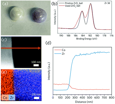
Our group has applied the mechanochemical technique (using a plenary ball mill) to fabricate crystalline MOF powders.22 The only disadvantage of the entire procedure is the time-consuming washing of used jars and milling balls. For example, after the synthesis of Co-ZIF-62 [Co(Im)1.75(bIm)0.25], ZrO2 milling balls retained their purple colour of MOFs even after extensive physical cleaning (e.g. overnight sonicating in ethanol or water) (Fig. 1a), indicating the preservation of Co-based compounds. This observation compelled us to investigate the interaction between the balls and the surface coated MOFs. It indicates the formation of a thin and robust Co-containing surface deposition layer on the highly inert ZrO2 balls after the mechanochemical reaction, which is confirmed via scanning electron microscope (SEM) secondary electron image combined with energy dispersive X-ray spectroscopy (EDS) mapping (Fig. S1†) as well as X-ray photoelectron spectroscopy (XPS) of the Co 2p spectra on the used ZrO2 ball (Fig. S2†). X-ray diffraction peaks for Co-ZIF-62 were not found in these milling ball samples, possibly due to the extensive ball milling and sonication (Fig. S3†). The XPS (Fig. 1b) spectra show that after ball milling with Co-ZIF-62, the Zr 3d XPS features become significantly broader, indicating a change in bonding environments for Zr attributing to a strong interaction between the surface coated Co-compound and the balls.We then looked at the microscopic elemental distribution on the surface of these samples. For the used ZrO2 ball surface, a 100 nm thick cross-sectional lamellar was cut using focused ion beam scanning electron microscopy (FIB-SEM). The presence of a ca. 100 nm thick diffusion layer of Co element towards the bulk of ZrO2 phase is revealed by energy dispersive X-ray spectroscopy (EDS) line-scan and mapping performed by transmission electron microscopy (TEM) (Fig. 1c–e), indicating the formation of an alloyed interfacial layer after ball milling through the mechanical treatment.
Ball milling can generate a considerable amount of energy by producing simultaneous heat and mechanical stress, which promotes the interdiffusion of Co and Zr atoms at the interface. The technique has traditionally been used to create homogeneous, nonporous metallic alloy coatings on rigid metallic substrates: the mechanical impact can cause surface defects and wear on the substrates, which allow bonding and atomic alloying with the coating materials.23–26 Despite the fact that ZrO2 balls are highly chemically and physically inert, we identified the formation of interfacial interaction with Co in this work, leading to a stable coating and implying that the coating technique can be further expanded to other less inert substrates.
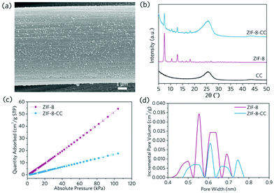
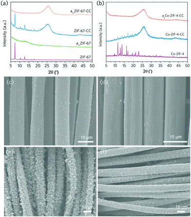
As a result, we looked into whether the mechanochemical technique could be used to create MOF coatings on soft, flexible substrates without any pre-treatment or the use of binders. Carbon cloth has been widely used as a MOF coating substrate for a variety of applications such as energy storage, electrocatalysis, sensing, and dye-sensitised solar cells due to its satisfactory electronic conductivity, satisfactory chemical inertness and commercial availability.27–30 However, surface activation or the application of a secondary binder is commonly required as necessity to produce high-quality and stable MOF coatings. However, these extra intermediate layers may impede electron transfer between MOF active sites and conductive substrates in sensing, energy storage and electrocatalysis applications. To generate MOF coating on the surface of the carbon cloth through mechanochemical treatment, we taped the pristine, non-activated carbon cloth to the inner wall of the ball milling jar and milled it for 3 minutes at 230 rpm with the pre-synthesised prototypical ZIF-8 powders (Fig. S4 and S5†). The substrate was then retrieved and sonicated with ethanol to remove any loosely attached ZIF-8 particles. According to the SEM image, the retained ZIF-8 coating on carbon cloth is smooth and even, showing an average particle size of ca. 100 nm (Fig. 2a and Fig. S6†). X-ray diffraction (XRD) and gas adsorption results both confirm the preservation of the anchored ZIF-8's highly porous, crystalline structures (Fig. 2b–d and Fig. S7†). The obtained ZIF-8 coating layer is relatively stable: it exhibits negligible coating material loss even after 100 cycles of manual bending, according to the Zn loading determined by the inductively coupled plasma optical emission spectroscopy (ICP-OES, Table S1†).
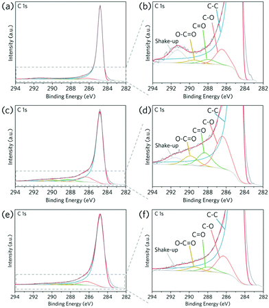
In terms of the coating mechanism, similar to the ZrO2–MOF system, an atomic inter-diffusion layer is expected to form after ball milling at the interface between carbon cloth and MOFs, providing an alloyed interfacial layer leading to stable anchoring for the coated ZIF-8. It should be noted that the surface chemical functional groups can also be generated by high energy mechanochemical treatment: non-activated carbon cloth can be oxidised via ball milling,31 resulting in higher contents of surface functional groups as probed by XPS (Fig. 3a–d and Table 1). This can be attributed to the oxidation of unsaturated carbon sites, either at the edges of the graphene layers or in the basal plane defects, or to the carboxylic group conversion under mechanochemical treatment.32 They are consistent with the Raman spectroscopy, where the broadening of peaks after ball milling confirms the change of chemical states for the carbon cloth (Fig. S8†).
| Fraction of functional groups in C 1s spectra (%) | |||||
|---|---|---|---|---|---|
| Sample | Graphite | C–O | C![[double bond, length as m-dash]](https://www.rsc.org/images/entities/char_e001.gif) O O |
O–C![[double bond, length as m-dash]](https://www.rsc.org/images/entities/char_e001.gif) O O |
Shake-up |
| Pristine CC | 89.7 | 4.2 | 1.3 | 1.0 | 3.8 |
| CC after ball milling in air | 76.1 | 12.1 | 5.1 | 3.6 | 3.1 |
| CC after ball milling in argon | 85.8 | 8.6 | 2.3 | 2.0 | 1.3 |
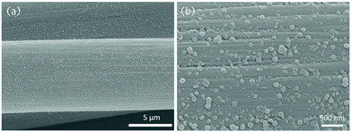
It is worth noting that mechanical activation of carbon cloth can also be done in an inert environment (e.g. Ar). After ball milling carbon cloth in an Ar environment, the contents of all surface oxide functional groups also increased (Fig. 3e–f and Table 1). The emerging surface oxide functional groups on carbon cloth can serve as anchoring sites for MOFs on top of the interdiffusion layer. In the case of ZIF-8, these acidic sites can bond with metal ions, which promotes MOF deposition onto carbon cloth. As a result, the mechanochemical MOF coating in an inert atmosphere also resulted in a homogeneous coating layer on carbon cloth (Fig. 4). This provides a high freedom degree when it comes to processing chemically sensitive MOFs.
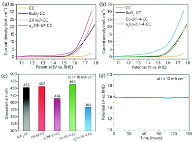
We further explored the interfacial energy transfer between the coated MOFs and the conductive substrate. This is the key enabler for a series of electrocatalysis, sensing and energy-related applications. To probe its feasibility, electrocatalytic Co-based ZIFs (ZIF-67 and Co-ZIF-4) were coated onto the surface of non-prefunctionalised carbon cloth via ball milling, and the resultant nanocomposite electrodes were tested for electrocatalytic oxygen evolution reaction (OER) reaction, which is an important reaction for energy conversion.33,34 In the meantime, commercial RuO2 was coated onto carbon cloth (RuO2) using the same method, and applied as the reference electrocatalysts. In order to create more active sites on ZIF-67 and Co-ZIF-4 to improve the OER activities, ZIF-67 crystal was amorphised by ball milling under 800 rpm for 15 min (denoted to as amZIF-67, Fig. S9, S10a andb†). In parallel, Co-ZIF-4 crystal was coated on the carbon cloth first and then amorphised through high-temperature melt-quenching at 560 °C under argon environment (referred to as agCo-ZIF-4, S10c andd). A particular smooth surface morphology with a high surface coverage was obtained for the thermally amorphised Co-ZIF-4 (Fig. 5e and f, Fig. S11c and d†). The loading of electrocatalysts on CC were determined by ICP-OES and the results are shown in Table S2.†
Subsequently, the ZIF-67, amZIF-67, Co-ZIF-4 and agCo-ZIF-4 carbon cloth electrodes were tested for OER in 0.1 M O2-saturated KOH aqueous solution. As shown in Fig. 6a–c, ZIF-67-CC and Co-ZIF-4-CC require respectively 457 mV and 464 mV of overpotential to generate a 10 mA cm−2 of current density, which are comparable with that of the carbon cloth electrode with commercial RuO2. After the amorphisation, the overpotential can be reduced effectively to 414 mV (amZIF-67) and 383 mV (agCo-ZIF-4-CC). The amorphisation can effectively promote the catalytic efficiency, which is in line with the literature.35,36 This also confirms the high level of flexibility of the mechanochemical coating technique, which works for different types of MOFs, and offers great potential for functionalisation and modification. The stability of agCo-ZIF-4-CC was further evaluated using chronopotentiometry under a current density of 10 mA cm−2 for 150 h in 0.1 M KOH with constant stirring (Fig. 6d). agCo-ZIF-4-CC showed excellent stability during the 150 h testing, confirming the great practicality for the MOF-coated carbon cloth electrodes fabricated by the mechanochemical technique.
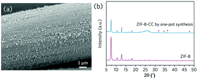
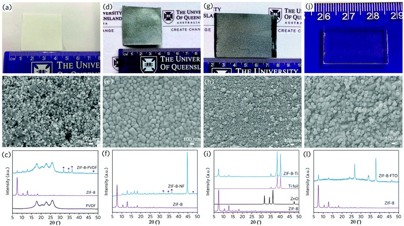
Given that ZIF-8 can be synthesised mechanochemically from zinc oxide and 2-methylimidazole ligands, we demonstrated the viability of a one-pot strategy for synthesising ZIF-8 coatings onto carbon cloth directly from stoichiometric precursors (Fig. 7). To test the versatility of this technique, we used a variety of flexible substrates, including polyvinylidene fluoride (PVDF) microfiltration membranes, nickel foams, and titanium foils (SEM images of the uncoated substrates in Fig. S12a–f†). Similarly, these flexible substrates were taped to the inner wall of a ball milling jar and then milled with a plenary ball milling machine in the presence of ZIF-8 precursors (stochiometric zinc oxide and 2-methylimidazole). The presence of signature diffraction peaks from the XRD confirms the generation of ZIF-8 surface coating layers, and the nanoparticle size is relatively even with a high surface coverage (Fig. 8a–i, Fig. S13–S15†).
For one-pot ZIF-8 coated on carbon cloth, PVDF and nickel foam, XRD patterns reveal the presence of a certain amount of the unreacted zinc oxide (Fig. 7b, 8c and f), possibly due to the trapping of the precursor within the porous structures of these substrates. In comparison, high conversion of the precursor was achieved for the one-pot coating on dense titanium foil substrates (Fig. 8i), which was also confirmed by the UV-Vis absorption spectra (Fig. S16†). Gas adsorption results confirm the highly porous structure of the ZIF-8 coated on titanium foil prepared by one-pot synthesis from the precursor (Fig. S15c and d†). The effective generation of MOF coating directly from precursor demonstrates the high flexibility of this coating technique. Furthermore, the technique is easily scalable – we demonstrated the coating of ZIF-8 onto a 5.5 × 11 cm carbon cloth substrate using a large ball milling jar (Fig. S17†). Furthermore, the nature of mechanochemical treatment facilitates coating control. We can create dual side MOF coatings on a porous Matrimid support, with hierarchical structures for specific applications (Fig. S18†).
The coating technique's great flexibility and versatility have been demonstrated with flexible substrates. We investigated the MOF coating on flat, rigid and brittle glass substrates further. A transparent fluorine-doped tin oxide (FTO) conductive glass substrate (Fig. S12g–h†) was mounted onto the inner jar wall and ball-milled with pre-synthesised ZIF-8 powders. Though the rotational speed had to be carefully controlled (200 rpm) to avoid excessive mechanical stress on the substrate, an evenly distributed nanocrystal ZIF-8 coating layer was formed on the substrate, filling the valleys between the FTO crystal grains in particular (Fig. 8j–l, Fig. S19a–b†). Further XPS results indicate the formation of interfacial bonding between two phases, given the shift of the peak position for Sn and Zn peaks after ZIF-8 deposition (Fig. S19c–d†). This ensures the intimate and stable coating, paving the way for real applications, such as electrodes and sensors.
Conclusions
This contribution describes a versatile, scalable, and simple technique to generate nanosized ZIF coatings, demonstrating that stable ZIF coating can be generated using a simple solid-state mechanochemical treatment. Further studies revealed the presence of an interdiffusion layer and substrate functionalisation groups after the ball milling, rendering the stable coating for the MOFs. The simple coating layer also allows a high level of flexibility in terms of functionalisation and modification, enabling electrocatalysis applications. It is expected that the platform technology can create MOF coated devices with good stability and interfacial energy transfer, and it can be easily applied to rigid and flexible materials. The method paves the way for the development of low-cost MOF devices for separation, catalysis, sensing, and optical applications.Author contributions
RL: conceptualisation, formal analysis, investigation, methodology, writing – original draft, writing – review & editing. YY: methodology, investigation. MYBZ: investigation. XL: investigation. SG: investigation. WH: investigation. SS: funding acquisition. ML: investigation, writing – review & editing. LW: supervision, writing – review & editing. VC: resources, supervision, funding acquisition, writing – review & editing. JH: conceptualisation, project administration, resources, supervision, writing – review & editing, funding acquisition.Conflicts of interest
There are no conflicts to declare.Acknowledgements
Dr Jingwei Hou would like to acknowledge the financial support from the Australian Research Council (DE190100803), UQ ECR Grant (UQECR2057677) and UQ Dow Center for Sustainable Engineering Innovation for the seed grant. This work was performed in part at the Queensland node of the Australian National Fabrication Facility. A company established under the National Collaborative Research Infrastructure Strategy to provide nano and microfabrication facilities for Australia's researchers. The authors acknowledge the facilities, and the scientific and technical assistance, of the Australian Microscopy & Microanalysis Research Facility at the Centre for Microscopy and Microanalysis, The University of Queensland.Notes and references
- A. E. Baumann, D. A. Burns, B. Liu and V. S. Thoi, Commun. Chem., 2019, 2, 86 CrossRef.
- Q. Wang and D. Astruc, Chem. Rev., 2020, 120, 1438–1511 CrossRef CAS PubMed.
- L. Chen, X. Zhang, X. Cheng, Z. Xie, Q. Kuang and L. Zheng, Nanoscale Adv., 2020, 2, 2628–2647 RSC.
- M. Zhang, X. Wang, R. Lin, Y. Liu, F. Chen, L. Cui, X. Meng and J. Hou, J. Membr. Sci., 2021, 618, 118630 CrossRef CAS.
- Z. Sun, H. Jin, Y. Sun, X. Jiang and R. Gui, Nanoscale, 2020, 12, 14538–14548 RSC.
- Z. Sun, Y. Sun, M. Yang, H. Jin and R. Gui, Nanoscale, 2021, 13, 13014–13023 RSC.
- R. Freund, O. Zaremba, G. Arnauts, R. Ameloot, G. Skorupskii, M. Dinca, A. Bavykina, J. Gascon, A. Ejsmont, J. Goscianska, M. Kalmutzki, U. Lachelt, E. Ploetz, C. S. Diercks and S. Wuttke, Angew. Chem., Int. Ed., 2021, 60, 23975–24001 CrossRef CAS PubMed.
- T. D. Bennett, F.-X. Coudert, S. L. James and A. I. Cooper, Nat. Mater., 2021, 20, 1179–1187 CrossRef CAS PubMed.
- J. Hou, A. F. Sapnik and T. D. Bennett, Chem. Sci., 2020, 11, 310–323 RSC.
- J. Hou, M. L. R. Gómez, A. Krajnc, A. McCaul, S. Li, A. M. Bumstead, A. F. Sapnik, Z. Deng, R. Lin, P. A. Chater, D. S. Keeble, D. A. Keen, D. Appadoo, B. Chan, V. Chen, G. Mali and T. D. Bennett, J. Am. Chem. Soc., 2020, 142, 3880–3890 CrossRef CAS PubMed.
- T. Tian, Z. Zeng, D. Vulpe, M. E. Casco, G. Divitini, P. A. Midgley, J. Silvestre-Albero, J.-C. Tan, P. Z. Moghadam and D. Fairen-Jimenez, Nat. Mater., 2018, 17, 174–179 CrossRef CAS PubMed.
- J. Hou, P. D. Sutrisna, Y. Zhang and V. Chen, Angew. Chem., Int. Ed., 2016, 55, 3947–3951 CrossRef CAS PubMed.
- Y. Chen, S. Li, X. Pei, J. Zhou, X. Feng, S. Zhang, Y. Cheng, H. Li, R. Han and B. Wang, Angew. Chem., Int. Ed., 2016, 55, 3419–3423 CrossRef CAS PubMed.
- M. Rimoldi, V. Bernales, J. Borycz, A. Vjunov, L. C. Gallington, A. E. Platero-Prats, I. S. Kim, J. L. Fulton, A. B. F. Martinson, J. A. Lercher, K. W. Chapman, C. J. Cramer, L. Gagliardi, J. T. Hupp and O. K. Farha, Chem. Mater., 2017, 29, 1058–1068 CrossRef CAS.
- I. Stassen, M. Styles, G. Grenci, H. V. Gorp, W. Vanderlinden, S. D. Feyter, P. Falcaro, D. D. Vos, P. Vereecken and R. Ameloot, Nat. Mater., 2016, 15, 304–310 CrossRef CAS PubMed.
- M. Klimakow, P. Klobes, A. F. Thünemann, K. Rademann and F. Emmerling, Chem. Mater., 2010, 22, 5216–5221 CrossRef CAS.
- T. H. Wei, S. H. Wu, Y. D. Huang, W. S. Lo, B. P. Williams, S. Y. Chen, H. C. Yang, Y. S. Hsu, Z. Y. Lin, X. H. Chen, P. E. Kuo, L. Y. Chou, C. K. Tsung and F. K. Shieh, Nat. Commun., 2019, 10, 5002 CrossRef PubMed.
- W. Sun, X. Zhai and L. Zhao, Chem. Eng. J., 2016, 289, 59–64 CrossRef CAS.
- L. Frentzel-Beyme, M. Kloss, P. Kolodzeiski, R. Pallach and S. Henke, J. Am. Chem. Soc., 2019, 141, 12362–12371 CrossRef CAS PubMed.
- R. Lin, X. Li, A. Krajnc, Z. Li, M. Li, W. Wang, L. Zhuang, S. Smart, Z. Zhu, D. Appadoo, J. Harmer, Z. Wang, A. G. Buzanich, S. Beyer, L. Wang, G. Mali, T. D. Bennett, V. Chen and J. Hou, Angew. Chem., Int. Ed., 2021 DOI:10.1002/anie.202112880.
- F. Russo, R. Castro-Muñoz, F. Galiano and A. Figoli, J. Membr. Sci., 2019, 585, 166–174 CrossRef CAS.
- J. Hou, P. Chen, A. Shukla, A. Krajnc, T. Wang, X. Li, R. Doasa, L. H. G. Tizei, B. Chan, D. N. Johnstone, R. Lin, T. U. Schülli, I. Martens, D. Appadoo, M. S. Ari, Z. Wang, T. Wei, S.-C. Lo, M. Lu, S. Li, E. B. Namdas, G. Mali, A. K. Cheetham, S. M. Collins, V. Chen, L. Wang and T. D. Bennett, Science, 2021, 374, 621–625 CrossRef CAS PubMed.
- Z. Zhan, Y. He, D. Wang and W. Gao, Intermetallics, 2006, 14, 75–81 CrossRef CAS.
- A. Canakci, F. Erdemir, T. Varol and S. Ozkaya, Powder Technol., 2013, 247, 24–29 CrossRef CAS.
- I. Farahbakhsh, A. Zakeri, P. Manikandan and K. Hokamoto, Appl. Surf. Sci., 2011, 257, 2830–2837 CrossRef CAS.
- R. Pouriamanesh, J. Vahdati-Khaki and Q. Mohammadi, J. Alloys Compd., 2009, 488, 430–436 CrossRef CAS.
- S. Xu, R. Liu, X. Shi, Y. Ma, M. Hong, X. Chen, T. Wang, F. Li, N. Hu and Z. Yang, Electrochim. Acta, 2020, 342, 136124 CrossRef CAS.
- Q. Zha, M. Li, Z. Liu and Y. Ni, ACS Sustainable Chem. Eng., 2020, 8, 12025–12035 CrossRef CAS.
- X. Gao, S. DelaCruz, C. Zhu, S. Cheng, D. Gardner, Y. Xie, C. Carraro and R. Maboudian, Carbon, 2019, 148, 64–71 CrossRef CAS.
- T.-Y. Chen, Y.-J. Huang, C.-T. Li, C.-W. Kung, R. Vittal and K.-C. Ho, Nano Energy, 2017, 32, 19–27 CrossRef CAS.
- L. L. Matović, N. S. Vukelić, U. D. Jovanović, K. R. Kumrić, J. B. Krstić, B. M. Babić and A. B. Đukić, Arabian J. Chem., 2019, 12, 4446–4457 CrossRef.
- J. L. Figueiredo, J. Mater. Chem. A, 2013, 1, 9351–9364 RSC.
- S. Zhao, C. Tan, C.-T. He, P. An, F. Xie, S. Jiang, Y. Zhu, K.-H. Wu, B. Zhang, H. Li, J. Zhang, Y. Chen, S. Liu, J. Dong and Z. Tang, Nat. Energy, 2020, 5, 881–890 CrossRef CAS.
- J.-Q. Shen, P.-Q. Liao, D.-D. Zhou, C.-T. He, J.-X. Wu, W.-X. Zhang, J.-P. Zhang and X.-M. Chen, J. Am. Chem. Soc., 2017, 139, 1778–1781 CrossRef CAS PubMed.
- C. Liu, J. Wang, J. Wan, Y. Cheng, R. Huang, C. Zhang, W. Hu, G. Wei and C. Yu, Angew. Chem., Int. Ed., 2020, 59, 3630–3637 CrossRef CAS PubMed.
- J. Li, W. Huang, M. Wang, S. Xi, J. Meng, K. Zhao, J. Jin, W. Xu, Z. Wang, X. Liu, Q. Chen, L. Xu, X. Liao, Y. Jiang, K. A. Owusu, B. Jiang, C. Chen, D. Fan, L. Zhou and L. Mai, ACS Energy Lett., 2019, 4, 285–292 CrossRef CAS.
Footnote |
| † Electronic supplementary information (ESI) available. See DOI: 10.1039/d1nr08377e |
| This journal is © The Royal Society of Chemistry 2022 |


