 Open Access Article
Creative Commons Attribution 3.0 Unported Licence
The crystalline state of rubrene materials: intermolecular recognition, isomorphism, polymorphism, and periodic bond-chain analysis of morphologies†
Massimo
Moret
 *a and
Angelo
Gavezzotti
 b
b
aDepartment of Materials Science, University of Milano – Bicocca, Italy. E-mail: massimo.moret@unimib.it
bDepartment of Chemistry, University of Milano (retired), Italy. E-mail: angelo.gavezzotti@unimi.it
First published on 30th March 2022
Abstract
A survey of all crystal structures of rubrene materials in the Cambridge Structural Database is presented. Although the chemical substitution landscape is wide, hydrogen bonding functionalities are absent. Recognition motifs frequently found in crystals are the “slipped-cofacial” molecular pairing, and herringbone or purely translational 3-D propagation. Packing modes are classified in terms of structure determinants, cohesive energies of pairs of molecules in closer contact computed by the CLP atom-atom potential field. In these terms, crystal isomorphism with different chemical substitution is quantitatively assessed. Polymorphs are relatively few, perhaps due to poor solubilities that hamper crystallization screenings. True polymorphs are also identified by structure determinant patterns, and a new polymorph of the di-p-nitrophenyl derivative has been prepared and characterized by X-ray diffraction. Crystal morphologies of selected rubrenes have been predicted by Hartman's Periodic Bond Chain approach using PIXEL attachment energies; there is good agreement with experimental morphologies of crystals grown by sublimation. The good results obtained by CLP and PIXEL show promise for a computationally cheap access to lattice energies and morphology prediction. In general, from our overview it looks like sensitive spots in the driving forces for rubrene packing are the 4-substitution sites at the lateral rings, with substituents of moderate steric bulk. Peripheral substitution at the tetracene core seems to be less relevant. Our survey provides a structural background fostering new ideas on the synthesis and planning of physical properties of rubrenes.
Introduction
Organic semiconductors have been for a long time under scrutiny for the development of organic electronic devices.1,2 Among a host of molecular candidates, rubrene (5,6,11,12-tetraphenyl-tetracene) has been at the forefront of research after discovery of the high charge-carrier mobility of its orthorhombic polymorph.3,4 Although organic semiconductors have not yet reached performance levels suitable for extensive marketing, the synthesis and the characterization of rubrene derivatives are still highly attractive.5A primary issue is the design of high yield chemical synthetic paths, but a better understanding of the solid-state properties of these organic crystals is also desirable because physical properties depend on detail of crystal packing. Intermolecular interactions determine the crystal structure, influencing charge-carrier mobility, transfer integrals and exciton diffusion length.6 Bulk charge-transport properties are related to π-stacking interactions, arising from orbital overlap of adjacent molecules. In the nearest-neighbor stacking arrangement of the rubrene crystal the presence of lateral phenyls forces a slippage on the long molecular axis of the tetracene core, forming a hopping pair called “slipped-cofacial1”7 with a distance of 3.74 Å, larger than in typical π-stacks8,9 and in tetracene itself.7 Stacking geometries are also influenced by the twisting of the tetracene core imposed by intramolecular strain. The pair propagates in rows that are the main direction of conduction10 with a high value of the transfer integrals.11 These rows often pack in a zig-zag fashion, giving the crystal the so-called “herringbone” shape (Fig. 1).
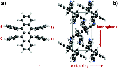 | ||
| Fig. 1 (a) The rubrene molecule with position numbering of phenyl, thiophene, furan or pyridine rings. (b) Some key structural features in rubrene crystals: π-stacking is in the slipped-cofacial form. Tetracene rings are seen edge-on (example taken from CIYYAM, see Table 1). | ||
The preparation of effective semiconducting organic materials depends on (i) finding molecules with improved solubility and stability against light and/or oxygen degradation12 (lack of these features is a drawback of pristine rubrene); and (ii) obtaining crystal structures with planar polyacene cores and optimum π–π overlap. The task is, to say the least, awkward. In fact, previous analyses of crystal packing in rubrene derivatives (see ref. 5 and references therein) focussed on π–π stacking distances, slip distances and angles, tetracene planarity, herringbone angles, trying to find a rationale for enhancement of transport properties through chemical modification. However, a study based on graphical tools found little or no correlation between planarity of the tetracene core and the nature of lateral substituents.13
Modification of the rubrene molecule at the rim of the tetracene core frequently results in the disruption of the herringbone motif and/or significant twisting of the tetracene backbone. Partial or complete tetracene fluorination provides a planar tetracene core in only two cases but with loss of the favourable rubrene packing mode.14,15 A more promising route involves substitution at the para and meta positions of the attached phenyl rings, trying to preserve both a planar tetracene core and the (200) slice of orthorhombic rubrene.16,17 These new derivatives allowed a characterization of oxygen/light stability and charge transport properties, providing new hints about the relation between molecular architectures, crystal structures and physical properties. With introduction of para functional groups on centrosymmetric rings 5 and 1117 the unmodified tetracene core preserved the structural motif of the (200) monomolecular slice, although the stacking of layers was no longer feasible in the orthorhombic system due to the increased corrugation of the (h00) surface. The strong repulsion caused by crowded peripheral phenyl rings can be reduced by twisting of the tetracene backbone, resulting in a conformation that is the most stable for molecules in solution, vapour phase and amorphous solids.18–20 Tetracene twisting is detrimental to the desired electronic properties; unfortunately, this is observed in about half of the crystalline derivatives, due to a combination of intra- and intermolecular steric factors.
Polymorphism is also an issue. Pristine rubrene has three polymorphs (orthorhombic, monoclinic and triclinic) obtained under ambient conditions by crystallization from different solvents or by vacuum techniques, plus a high-pressure triclinic structure stable above ca. 6 GPa.21 The mobility in the orthorhombic polymorph22 is an order of magnitude greater than that of the triclinic polymorph, that has a different propagation pattern and a smaller short-axis displacement.23 The monoclinic polymorph shows no π-stacking with a corresponding poor performance.24
The main task of organic crystal chemistry is to trace a consequential connection between molecular structure and crystal packing, at least in its essential features if not in a complete crystal structure prediction. Such studies rely on a statistical approach based on crystal and molecular geometries as found in experimental diffraction work, supplemented by a quantitative analysis of packing energies and forces. Previous attempts on various small subsets of functionalized rubrenes tried to extract general trends;13,18,25–27 we present here a survey of molecular and crystal properties of 33 tetra(ring)-substituted tetracenes with rubrene-like architecture, fully characterized by single-crystal X-ray diffraction, along with a detailed analysis of their intermolecular energies and crystal packing modes. In a different perspective to the same aim, the equilibrium and growth morphologies of crystals of orthorhombic rubrene and four monoclinic derivatives17 have been modeled. Crystal morphology depends mainly on intermolecular potentials that determine anisotropic growth forces, but other external, thermodynamic, and kinetic factors are at work, including supersaturation, temperature, pH, the influence of solvent, of impurities or additives, and the presence of electromagnetic or mechanical fields. The theoretical crystal morphology can be derived solely from the crystal structure by Periodic Bond Chain (PBC) methods,28–30 whereby a crystal structure is seen as a 3D array of uninterrupted chains of strong bonds with the crystal's stoichiometry, running along specific crystallographic [uvw] directions. The method works under the assumptions that (i) crystal growth is controlled by surface processes (incorporation of growth units); (ii) during crystal growth strong intermolecular bonds are formed between growth units; (iii) external factors play only a minor role (growth performed at low/moderate supersaturations). Obviously, a reliable method for the quantitative evaluation of the energies of these bonds must be available.
Results and discussion
Structure screening: a normalized dataset of rubrenes
Table S1 (ESI†) has a list of all the rubrene crystal structures in the Cambridge Structural Database (CSD,31 labeled by their six-letter Refcode identifier). A preliminary screening to assess the adaptability of each structure to a systematic crystal packing analysis was carried out, as described below. The main features that guided the selection were (a) 5,6,11,12-substitution only by ring compounds, phenyls, furans, pyridines, or thiophenes; (b) available unit cell dimensions, space group and atomic coordinates for all non-hydrogen atoms; (c) no unresolved disorder; (d) R-factors below 7.5% (with one exception). Unreliable or absent hydrogen atom positions were corrected or provided by standard procedures in ad hoc modules of the MiCMoS platform (see the documentation at sites.unimi.it/xtal_chem_group/). The MiCMoS module Crysaa was used to make sure that no undetected errors in atom positions, space group assignment, etc., were present. The presently determined structure of a polymorph of CIYNAB, provisionally labeled CIYNAB01, was also considered. Two resolved twins (RAGDEL, VICHAT) were included, and two partially disordered structures (RAGDAH, PIXPUJ01) were included using the major component of disorder. The polymorphs GORVIU, PIXPOD and PIXPUJ, although interesting, could not be included due to major disorder that prevents a unique analysis in our terms. The final dataset of 33 crystal structures (Table 1) can be used with confidence for further theoretical studies. A complete list of atomic coordinates including hydrogen atoms is available from the authors upon request.| Refcodea | Space group | Z | Z′c | Symd | Twiste | T/K | R fac | Description of substituentsg |
|---|---|---|---|---|---|---|---|---|
a Identification code of the Cambridge Structural Database (CSD).
b Molecules in unit cell.
c Molecules in asymmetric unit.
d Intramolecular symmetry: I inversion, A twofold axis, M mirror.
e C–C–C–C cis torsion angle across the central C![[double bond, length as m-dash]](https://www.rsc.org/images/entities/char_e001.gif) C bond in tetracene (trans is 180-cis).
f Crystallographic R-factor.
g Ph = phenyl, Me = methyl, t-Bu = tert-butyl, CF3 = trifluoromethyl. In PhX codes, the X substituent is in the para position unless otherwise stated.
h Substitution at the tetracene ring.
i Major component of disorder.
j Resolved twin. C bond in tetracene (trans is 180-cis).
f Crystallographic R-factor.
g Ph = phenyl, Me = methyl, t-Bu = tert-butyl, CF3 = trifluoromethyl. In PhX codes, the X substituent is in the para position unless otherwise stated.
h Substitution at the tetracene ring.
i Major component of disorder.
j Resolved twin.
|
||||||||
| AXIDER | P21/c | 2 | 1/2 | I | 0 | 293 | 6.35 | 5,11(PhF) 6,12(Ph) T(2,8Fluoro)h |
| CIYNAB | P21/c | 2 | 1/2 | I | 0 | 153 | 6.73 | 5,11(PhNO2) 6,12(Ph) |
| CIYNAB01 |
P![[1 with combining macron]](https://www.rsc.org/images/entities/char_0031_0304.gif) |
1 | 1/2 | I | 0 | 293 | 7.45 | 5,11(PhNO2) 6,12(Ph) |
| CIYXUF | P21/c | 2 | 1/2 | I | 0 | 123 | 6.59 | 5,11(Ph) 6,12(PhCF3) |
| CIYYAM | P21/c | 2 | 1/2 | I | 0 | 120 | 6.65 | 5,11(PhCN) 6,12(Ph) |
| GORVIU01 | P21/c | 4 | 1 | — | 18 | 93 | 4.60 | 5,6,11,12(Furan) |
| GORVUG |
P![[1 with combining macron]](https://www.rsc.org/images/entities/char_0031_0304.gif) |
2 | 1 | — | 18 | 93 | 4.50 | 5,6,11,12(MeFuran) |
| INELUK | P21/n | 4 | 1 | — | 25 | 123 | 5.62 | perfluororubrene |
| INELUK02 | P21/c | 2 | 1/2 | I | 0 | 173 | 4.50 | perfluororubrene |
| MIVCUR | C2/c | 12 | 3/2 | I | 0 | 173 | 4.75 | 5,6,11,12(PhMe) |
| MIVDAY | P21 | 2 | 1 | — | 18 | 173 | 4.31 | 5,12(PhMe2) 6,11(PhMe) |
| MIVDEC | Pna21 | 4 | 1 | — | 21 | 173 | 4.21 | 5,12(PhMe) 6,11(Ph) |
| MIVDOM | Pbcm | 4 | 1/2 | M | 0 | 123 | 7.61 | 5,12(PhMe) 6,11(PhCF3) |
| MIVDUS | Pnma | 4 | 1/2 | M | 0 | 123 | 4.59 | 5,12(Ph) 6,11(PhCF3) |
| PIFHIW | Pnma | 4 | 1/2 | M | 0 | 292 | 7.42 | 5,12(PhtBu) 6,11(Ph) |
| PIFHOC | P21/c | 4 | 1 | — | 24 | 292 | 9.77 | 5,11-(PhtBu) 6,12(Ph) |
| PIXPOD01 | P21/c | 4 | 1 | — | 20 | 93 | 5.01 | 5,6,11,12(Thiophene) |
| PIXPUJ01i | P21/c | 2 | 1/2 | I | 0 | 120 | 6.87 | 5,11(Thiophene) 6,12(Ph) |
| POGZIV | P21/c | 8 | 2 | — | 15, 20 | 294 | 6.91 | 5,12(Thiophene) 6,11(Ph) |
| QQQCIG05 | Cmca | 4 | 1/4 | I A M | 0 | 125 | 3.77 | 5,6,11,12(Ph) rubrene |
| QQQCIG13 | P21/c | 2 | 1/2 | I | 0 | 173 | 4.94 | 5,6,11,12(Ph) rubrene |
| QQQCIG14 |
P![[1 with combining macron]](https://www.rsc.org/images/entities/char_0031_0304.gif) |
1 | 1/2 | I | 0 | 173 | 6.72 | 5,6,11,12(Ph) rubrene |
| RAGCEK | P21/c | 4 | 1 | — | 11 | 123 | 5.59 | 5,12(Ph(CF3)2) 6,11(PhMe) |
| RAGCIO | P2/c | 4 | 1 | — | 0 | 123 | 6.14 | 5,12(PhtBu) 6,11(PhCF3) |
| RAGCUA | C2/c | 4 | 1/2 | A | 13 | 123 | 3.74 | 5,12(Ph) 6,11(C6F4CF3) |
| RAGDAHi | P21/n | 4 | 1 | — | 16 | 123 | 3.23 | 5,12(PhMe) 6,11(C6F4CF3) |
| RAGDEL |
P![[1 with combining macron]](https://www.rsc.org/images/entities/char_0031_0304.gif) |
2 | 1 | — | 13 | 123 | 4.71 | 5,12(C6F5) 6,11(Ph)j |
| RAGDIP |
P![[1 with combining macron]](https://www.rsc.org/images/entities/char_0031_0304.gif) |
2 | 2 | — | 0 | 123 | 3.89 | 5,6,11,12(C6F5) |
| RAGDOV | C2/c | 4 | 1/2 | A | 9 | 123 | 7.13 | 5,6,11,12(PhCF3) |
| TEFDUG | Pnna | 4 | 1/2 | A | 16 | 173 | 7.48 | 5,12(C6F5) 6,11(Ph) T(1,2,3,4Fluoro)h |
| TOMVOH | Pbca | 8 | 1 | — | 25 | 120 | 4.15 | 5,12(PhOMe) 6,11(Ph) |
| TOMWAU | P21/n | 4 | 1 | — | 20 | 120 | 5.59 | 5,12(PhF) 6(Ph) 11(PhOMe) |
| VICHAT |
P![[1 with combining macron]](https://www.rsc.org/images/entities/char_0031_0304.gif) |
1 | 1/2 | I | 0 | 100 | 4.09 | 6,12(Ph) 5,11(Pyridine)j |
Force field assessment
The choice of a suitable force field is imperative in the present case and must be made with a careful maximization of the efficiency/cost ratio. The focus being on intermolecular contact, all molecules are kept in the geometry determined by X-rays so that no intramolecular force field is necessary.Intramolecular energy terms can be neglected when discussing interaction energies between pairs of molecules, that are just tracers of the packing arrangement in the crystal. Intramolecular factors may be important for comparisons between total crystal energies; a procedure for an approximate evaluation will be described for the case of perfluororubrene (see below). The MiCMoS environment offers three schemes for intermolecular potentials, listed in order of increasing accuracy: (a) the AA-CLP formulation,32 an atom–atom scheme of entirely empirical origin, that requires only a few seconds; (b) the AA-LJC formulation,33 also atom–atom but requiring atomic point-charge parameters derived from an MP2-MO wavefunction; the molecular orbital calculation is demanding for the big rubrenes, but lattice energy calculations take fractions of a second; (c) the PIXEL scheme,34 that requires an MP2-level electron density and also a considerable amount of computing time for lattice calculations by finite integration of the various operators on the discrete wavefunction. The three methods work with default library parameters for organic compounds, and provide separate Coulomb, dispersion, and repulsion terms (CLP and Pixel also include a polarization term). Table S2 (ESI†) shows that the three approaches provide the same energy trends and often quite similar absolute energy values. Therefore, in large scale structure comparisons the cheapest CLP method was applied, while the accurate Pixel method was used in the analysis of periodic bond chains for some representative compounds. Table S3 (ESI†) collects the detail of partitioned lattice energies for all crystals in Table 1.
Crystallography of rubrenes: general aspects
The sample is too small for statistics on space group frequency, but the obvious P21/c is predominant. Depending on molecular constitution, rubrene molecules can have internal inversion, mirror or twofold axis symmetry preserved in the crystal, with 1/4, 1/2, 1, 3/2 or 2 molecules in the asymmetric unit. Although the shape of the basic packer is so irregular, packing coefficients are normal (0.68 to 0.74), and nearly all crystal structures show a 10–12-first-neighbor coordination sphere resembling a close packing of spheroids. There are no short atom–atom distances below the sum of contact radii, leaving no ground for the introduction of intermolecular “bonds”. Rubrene lattice energies are dominated by dispersive factors (Table S3, ESI†), because carbon and hydrogen atoms account for 91% of the total in the database, fluorine contributing another 7%, so that no “polar” groups are present. There are no hydrogen bond donors in our database, preventing a test of competition between dispersion and hydrogen bonding.Structure determinants and pairing symmetries
Intermolecular structure can be conveniently analyzed by partitioning the total lattice sums into interaction energies between pairs of molecules (Emm). While the lattice energy is comparable to sublimation heats, the Emm's are purely computational quantities, having no experimental counterpart. The Emm, the corresponding distance Rmm between molecular centers of coordinates, and the symmetry operator acting between the two partners, Omm, form a triad called a structure determinant. These determinants are of great help in a quantitative description and comparison of packing modes. In a way, they are zero-dimensional precursors of the periodic bond chains.Fig. 2a shows a histogram of the Rmm distribution, with peaks at the 7.0–7.25 and 7.75–8.0 Å bins. In fact, 21 out of 33 crystals show Rmm's of 7–8 Å either by translation (cell axis length) or by some other symmetry or asymmetry relationship. Fig. 2b shows the distribution of structure determinants. The plot has an obvious bias to higher Emm for shorter Rmm, meeting a lower limit at 7 Å. With few exceptions, translation and inversion are the only symmetries that allow a pairing below 8 Å and an energy in excess of 50 kJ mol−1. There is a dip in frequency between 9.5 and 11 Å, while the distribution levels at 10–25 kJ mol−1 with distances > 10 Å at second-neighbor stage, as recognition becomes less selective.
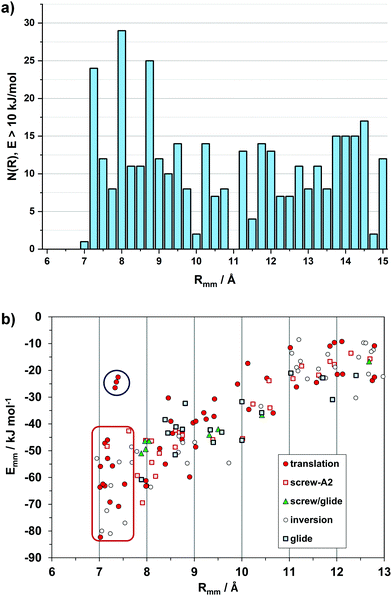 | ||
| Fig. 2 (a) Histogram of 436 distances between pairs of molecules (Rmm) whose stabilization energy is >10 kJ mol−1. (b) Energy/distance plot for the independent pairs with labeling of the symmetry operations, Omm. The red rectangle encloses the short distance, inversion-translation domain. See Fig. S1 (ESI†) for the outliers in the upper left part (blue circle, and Fig. S2 (ESI†) for the subset of slipped-cofacial. | ||
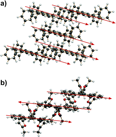
The most common coupling mode at short intermolecular distance is called “slipped-cofacial”, a parallel arrangement of the tetracenes allowing as much π-overlap as possible compatibly with the clash at the interlocking of lateral ring substituents. Fig. 3 shows some examples of these dimer structures, while Fig. S3 (ESI†) has an extended gallery of such coupling patterns. This mode occurs with 7 < Rmm < 8 Å, being called the SC7 mode. Fig. S2 and Table S4 (ESI†) show that there is no correlation between distance and energy because much depends also on the nature of the lateral substituents. This configuration is fostered almost exclusively by dispersion, although some charge-transfer contribution may be also present.
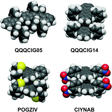 | ||
| Fig. 3 The slipped-cofacial arrangement: top, in two polymorphs of the parent compound; below: POGZIV shows a twisted tetracene core. Oxygen red, nitrogen blue, sulfur yellow. | ||
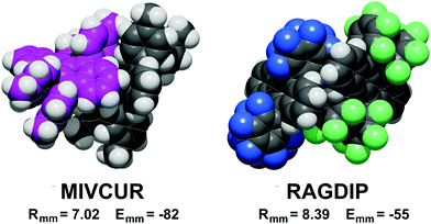
A definite symmetry relationship is not a prerequisite for short distance stabilization. The most stable pair in the database, −82 kJ mol−1, is the asymmetric pair in MIVCUR (Fig. 4). An example of infrequent short distance coupling over a screw axis is MIVDOM (Fig. S4, ESI†) with an Emm of −70 kJ mol−1 between non-parallel tetracene units. In a few cases, 7 Å couplings with low stabilization result from parallel tetracene cores without offset (Fig. S1, ESI†).
Coordination spheres and extended packing motifs
Since the reciprocal orientation of tetracene planes is so important for the physical properties of rubrenes, this feature is now taken as the leading one in the analysis of extended crystal packing. In the six P![[1 with combining macron]](https://www.rsc.org/images/entities/char_0031_0304.gif) space groups, and in two C2/c, Z′ = 1/2 space groups with the tetracene plane riding a twofold axis (see Table 1), any symmetry operation (translation, inversion and centering) can only produce a parallel alignment of tetracenes. The slipped-cofacial motif at 7 Å distance (“SC7” motif) is expanded by pure translation (Fig. 5a) or by inversion (Fig. 5b).
space groups, and in two C2/c, Z′ = 1/2 space groups with the tetracene plane riding a twofold axis (see Table 1), any symmetry operation (translation, inversion and centering) can only produce a parallel alignment of tetracenes. The slipped-cofacial motif at 7 Å distance (“SC7” motif) is expanded by pure translation (Fig. 5a) or by inversion (Fig. 5b).
In other Z′ = 1 structures with screw and/or glide operations the 3D expansion produces a corrugated arrangement of tetracenes. A classification of the structure expansion motifs includes the symmetry operators acting among nearest-neighbor molecules, while a measure of the corrugation is provided by the angles between vectors perpendicular to the average tetracene plane. Fig. S5 and Table S5 (ESI†) carry the detail of the classification. A first group includes 8 strictly similar structures with SC7 motif, an interplanar angle close to 60° and a fourfold cage provided by screw operators, as exemplified in Fig. 6a. A second group includes 7 structures whose motif is again a fourfold cage, but with 9 Å translation (Fig. 6b), and a less compact aggregation with a spread of interplanar angles. The aggregation motif in these two groups can be classified as fourfold “herringbone-cage”. Six other structures and the three structures with Z′ > 1 show packing motifs with a complex admixture of first neighbors over various symmetry elements that defies a simple classification.
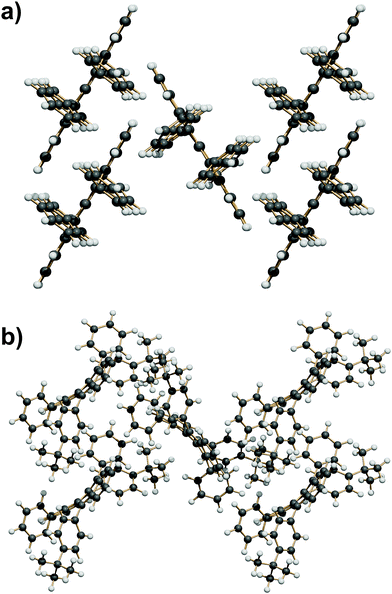 | ||
| Fig. 6 (a) The SC7 + 4 Screw herringbone-cage mode here exemplified by QQQCIG05 (compare with Fig. 1b). (b) The T9 + 4 Screw herringbone-cage mode here exemplified by PIFHOC. | ||
Isostructurality of rubrene crystals
The purely geometrical, qualitative analysis of packing modes can be supplemented by a quantitative analysis of coordination spheres by structure determinants, plotting molecule-molecule energies Emm against distance Rmm. These plots constitute a unique energetic profile of a crystal structure, by which similarities and differences can be better appreciated.35An exemplary case of isostructurality is seen in Fig. 7: four structures with same space group and nearly identical cell parameters (they are also isomorphous). All structures show the SC7 π-stacking pair, but being chemically different, the interaction energy varies from 45–55 kJ mol−1 in the three phenyl substituted compounds to 62 kJ mol−1 in the thiophene derivative, stabilized by a larger coulombic contribution. These considerations show that geometrical isomorphism is not always equivalent to energetic isostructurality. The SC7 mode is supplemented by a screw related pairing in the fourfold cage, of nearly identical stabilization in all four structures. The second coordination shell (upper right part of the plot) includes an admixture of screw and translation (T) determinants, in a common area although with minor energetic differences.
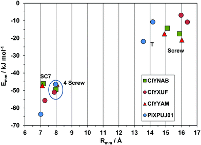 | ||
| Fig. 7 Energetic profiles (kJ mol−1) for a series of strictly isostructural crystals (see Table 1). SC7 = slipped-cofacial with 7 Å translation; 4 screw, coordination by 4 screw related molecules. The upper right part is manifold of closely related symmetries. | ||
A second very nearly isostructural series is shown in Fig. 8. The compounds are a hydrocarbon (QQQCIG13), a sparsely fluorinated compound (AXIDER) and a perfluoro derivative (INELUK02). The crystal structures are similar (same space group and cell parameters) but the energetic profile of the perfluoro compound shows a much larger cohesive energy in the first determinant, due to a substantial coulombic contribution (nearly zero in the other two structures). The second determinant is over a longer screw axis relationship, testifying a significant structure deformation due to perfluorination.
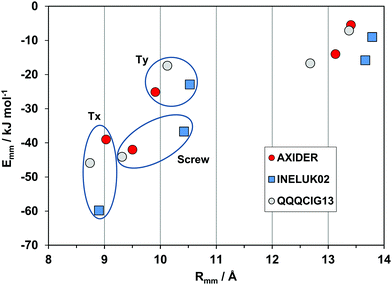 | ||
| Fig. 8 Energetic profiles (kJ mol−1) for a series of almost isostructural crystals (see Table 1). Tx, Ty: translation along cell edges. | ||
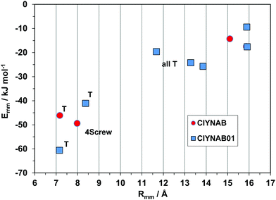
The triclinic structures of the parent hydrocarbon (QQQCIG14), of the newly determined polymorph CIYNAB01, and (strangely enough) of the compound in which two lateral phenyls are substituted by pyridines, are isomorphous (same cell parameters). The energy profiles in Fig. 9 prove that they are also isostructural, with a strict correspondence of the first two major determinants. The spread and minor differences in the second-neighbor coordination shell are marginally significant because the interaction energies are anyway small.
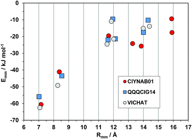 | ||
| Fig. 9 Energetic profiles (kJ mol−1) for a series of three isostructural triclinic crystals. All pairings are by pure translation. | ||
Polymorphism of rubrenes
The parent compound (database refcode QQQCIG, see Table 1) has three well described polymorphs, and our database includes two other cases of clear cut polymorphism (CIYNAB, INELUK). Other compounds (GORVIU, PIXPOD, PIXPUJ, CIYXUF) are apparently polymorphic, but one of the partners is heavily disordered; in such cases one may wonder whether the postulated polymorphism is a real material property or is rather the result of poor sample quality or handling. In any case these latter instances cannot be adapted to lattice energy analysis and were not considered.Polymorphism can be discussed qualitatively by comparisons of space groups and cell dimensions, or by packing diagrams, but such analyses are often ambiguous and always suffer from a certain amount of subjectivity. Especially in this case, the energetic profiles offer a univocal quantitative description of structure similarity or differences.
Fig. 10 shows the profiles for the three polymorphs of the parent hydrocarbon. The stable orthorhombic polymorph and the triclinic polymorph have the same slipped-cofacial pairing by 7 Å translation (SC7), but then all other determinants are completely different: in particular, the monoclinic polymorph with shortest contact distance of 8.7 Å stands out as clearly distinct from the other forms The second neighbor coordination sphere is also quite different in the three structures. These polymorphs are then three clearly distinct material phases, even though they have nearly identical densities and packing coefficients. The AA-CLP lattice energies (207, 205 and 196 kJ mol−1 for monoclinic, orthorhombic and triclinic, respectively) are only marginally different, as is very often the case in polymorphic groups. The tetracene core is flat in all polymorphs so that intramolecular energy differences may not be too large. Total energy differences between polymorphs should then be quite small, in agreement with the findings of quantum chemical calculations36 (≈2 kJ mol−1).
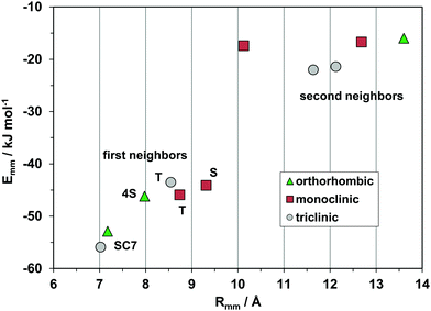 | ||
| Fig. 10 The energetic profile (kJ mol−1) of the three polymorphs of pristine rubrene, quantifying the different packings. | ||
Table 2 shows the energy profiles for two polymorphs that crystallize in the same space group but with quite different packing patterns. The polymorph with one full molecule in the asymmetric unit relies mostly on inversion-related neighbors, while the polymorph in which the molecule sits on a crystallographic inversion center (Z′ = 1/2) has translation and a fourfold of screw-related molecules in its coordination shell; determinant analysis gives a precise indication of the packing differences. INELUK was determined at lower temperature (123 vs. 173 K) but has nevertheless a lower density (1.93 vs. 2.04 g cm−3) and a lower packing coefficient (0.72 vs. 0.77): as expected, its total intermolecular energy is much less stabilizing, mainly due to a large deficiency in dispersion (close packing) terms. The tetracene core is flat in INELUK02 but twisted in INELUK, leading to a different overall conformation of the substituents. The non-bonded contact energy between pairs of lateral overlapping C6F5 groups, evaluated by the AA-CLP potentials, is destabilizing by 8 kJ mol−1 in INELUK02, but stabilizing by 4 kJ mol−1 in INELUK: our numbers are a clear indication of tradeoff between favorable intermolecular contact and a less favorable intramolecular conformation. Absolute values may not be good enough for a reliable estimate of the relative stability of the two polymorphs, for which a quantum chemical study36 predicted total energy differences of a few kJ mol−1. Although R-factors are comparable (4.5 vs. 5.6%), the unusually large lattice energy difference, together with the differences in densities and packing coefficients, suggest that INELUK is a metastable polymorph.
| Omm | R mm | Coul | Pol | Disp | Rep | E mm |
|---|---|---|---|---|---|---|
| INELUK P21/c Z = 4 | ||||||
| INV | 8.081 | −13.5 | −7.2 | −73.0 | 30.1 | −63.6 |
| INV | 8.663 | −8.3 | −6.2 | −57.9 | 21.8 | −50.6 |
| 2S | 10.593 | −5.7 | −5.3 | −48.0 | 25.0 | −34.0 |
| 2Ty | 11.149 | −6.7 | −3.6 | −28.9 | 13.1 | −26.2 |
| 2S | 11.618 | −4.5 | −4.3 | −35.4 | 22.3 | −21.8 |
| E latt | −34.6 | −35.4 | −229.3 | 115.1 | −184.2 | |
| INELUK02 P21/c Z = 2 | ||||||
| 2T | 8.902 | −20.4 | −6.3 | −64.4 | 31.4 | −59.8 |
| 4S | 10.423 | −8.1 | −5.3 | −48.3 | 25.0 | −36.7 |
| 2T | 10.527 | −0.5 | −4.0 | −32.0 | 13.6 | −22.9 |
| 4S | 13.665 | −3.5 | −3.3 | −24.9 | 15.9 | −15.8 |
| E latt | −47.5 | −38.6 | −262.4 | 133.4 | −215.1 | |
Fig. 11 shows the profiles for the CIYNAB and CIYNAB01 polymorph pair. Densities and packing coefficients of the two polymorphs are identical within a fraction of a percent, and lattice energies within 1 kJ mol−1, but the energy profiles are quite different, proving that CIYNAB01 is a legitimate new polymorphic material.
Periodic bond chains analysis of crystal morphologies
PBC theory37,38 has been long exploited for modeling theoretical crystal morphologies. Comparison with experimental outcomes provides useful information about the mechanism of growth processes at the crystal/environment interface.39 The PBC approach best works for growth at low supersaturation, without strong solute–solvent interactions (e.g. vacuum sublimation), and when intermolecular interactions in the growing crystal are dominated by fast decaying dispersive forces39–42 as the case of rubrenes. The underlying theory assumes that the time needed for the formation of a crystal bond decreases with increasing bond energy, leading to the kinetic equation Rhkl ∝ Ehklatt for flat (F) faces, where Rhkl is the growth rate of the (hkl) face and Ehklatt is the energy released per growth unit when a slice of dhkl thickness is attached to the surface.38 Therefore, the boundaries of crystal polyhedra are slowly growing faces, mainly flat (F) faces whose attachment energies are usually smaller than those of stepped or kinked faces.37,40We analyze here in these aspects a set of structures, the orthorhombic parent rubrene (QQQCIG15) and the isomorphous monoclinic derivatives (CIYNAB, CIYXUF, CIYYAM, PIXPUJ01, see Table 1). The growth morphologies of these crystals have been evaluated according to PBC methods28,29,40 using intermolecular interactions (called bonds) between first neighbors, whose energy is given by Emm values, derived from the more accurate force field formulation of the PIXEL approach, calculated between a reference molecule and the surrounding molecules within a cutoff of 25 Å. Bonds whose Emm was less than kT ≈ 4 kJ mol−1 (at the actual crystal growth temperature of 500–550 K) were discarded, leaving just four relevant bonds in the selected crystal structures.
The PBC analysis allows to identify crystal planes representing F faces, characterized by two or more non collinear periodic chains running parallel to the pertinent (hkl) plane. Slices of dhkl thickness agreeing with extinction rules of the space group42 represent physically sound molecular profiles of surfaces and natural growth layers. The growth units were defined as single molecules with a planar tetracene backbone as observed in the crystal structures. Attachment energies Ehklatt for F faces were calculated with the reference molecule interacting with a half crystal exposing the (hkl) plane, applying a 25 Å cutoff for distance between molecular centroids. They were corrected for the energy required to convert the tetracene backbone from the twisted conformation of vapor or solution to the planar one found in crystals, assuming an average value of 10 kJ mol−1 from the 6–16 kJ mol−1 range.18,20,36,43
Surface energies per unit area γhkl = Whkl/2Ahkl were estimated for a reference molecule attached to the (hkl) plane, where Whkl is the separation work required to split an infinite crystal along the (hkl) plane and Ahkl is the 2D unit cell area. Whkl has been estimated with the same Emm values used for attachment energies, with just minor approximation thanks to the fast decay of intermolecular (mainly dispersion) energies with distance. No significant reconstruction/relaxation has been observed in rubrene surfaces,44 supporting the application of Born–Stern definition with cuts of the bulk crystal structure. Theoretical equilibrium and growth crystal morphologies have been obtained with Wulff plots45 of γhkl and Ehklatt, respectively.
Table 3 lists molecule–molecule energies Emm defining bonds for orthorhombic rubrene. Crystal graphs of intermolecular bonds are reported in Fig. S6 (ESI†). The two strongest bonds a and b lie in the (200) slice and generate a robust growth layer with the slipped-cofacial motif. Within this slice the growth units are incorporated at the end of bond chains, resulting in layer-by-layer growth with stable and flat surface profiles. Experimental evidence from AFM imaging of rubrene {100} surfaces shows accordingly monomolecular (200) steps.46–48 The attachment energy of the {002} surface is more than twice that of {200}, due to the lower energy of the c bond. Flat faces {111} and {202} are further down the ranking of Ehklatt due to the presence of weaker d bonds. Interestingly, the {202} surfaces is similar to a stepped surface with [010] rows (the direction of the strongest bond and PBC) delimited by {200} and {002} facets connected through weak d bonds (Fig. S6, ESI†). This face does not appear in the theoretical growth morphology. Similarly, the high Ehklatt of face {020}, based only on d bonds, makes it disappear from the growth morphology while it is important in the equilibrium shape.
| Bonda | Symm. op.b | Distance | Bond energy |
|---|---|---|---|
| a Bond between the reference and a neighbor molecule. b Symmetry operation connecting reference and neighbor at the listed distance between centers of mass. c A slice is a set of layers with overall thickness dhkl. d Attachment energy corrected for twisted to flat tetracene backbone. e Surface energy, erg cm−2. Distances in Å, energies in kJ mol−1. | |||
| a | (x, 1 + y, z) | 7.173 | −64.8 |
| b | (−x, 1/2 − y, 1/2 + z) | 7.975 | −45.9 |
| c | (1/2 + x, 1/2 + y, z) | 13.866 | −17.8 |
| d | (1/2 − x, −y, 1/2 + z) | 15.171 | −6.5 |
| Flat face | Bonds in slicec | E att | γ hkl |
|---|---|---|---|
| {200} | a + 2b | −39.7 | 80.8 |
| {002} | a + 2c | −94.8 | 90.6 |
| {111} | b + c + d | −120.6 | 98.7 |
| {202} | a + d | −121.3 | 100.2 |
| {020} | 2d | −174.2 | 80.1 |
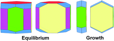
In summary, equilibrium, and even more strongly, growth morphology of orthorhombic rubrene is dominated by {200} surfaces characterized by the lowest Ehklatt and γhkl values (Fig. 12). As reported for other organic semiconductors40–42 the growth habit is in general less rich in crystal faces than the equilibrium one and displays a higher anisotropy, definitely tabular, determined by the robust slice containing the slipped-cofacial motif. On the contrary, all faces show similar γhkl, resulting in more isotropic equilibrium crystal habits.
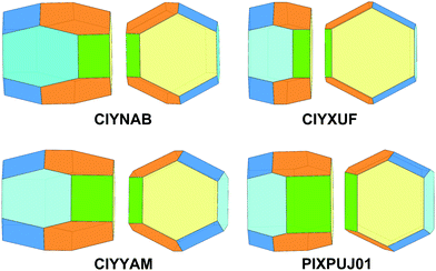
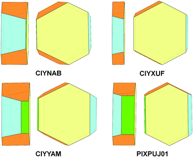
The four monoclinic rubrene derivatives are isomorphous despite different functional groups on rings 5/11 or the presence of thienyl instead of phenyl rings (Table 1). Table 4 shows the results of PBC analysis. All these structures display (100) slices with the slipped-cofacial motif found in the (200) slice of orthorhombic rubrene and share the same four strong bonds. These generate six PBCs ([100], [010], [001], 〈011〉, 〈201〉 and 〈211〉) and five flat faces: {100}, {10![[2 with combining macron]](https://www.rsc.org/images/entities/char_0032_0304.gif) }, {011}, {002} and {11
}, {011}, {002} and {11![[1 with combining macron]](https://www.rsc.org/images/entities/char_0031_0304.gif) }. An example of the crystal graph shared by all structures is reported in Fig. S7 (ESI†) for derivative CIYNAB.
}. An example of the crystal graph shared by all structures is reported in Fig. S7 (ESI†) for derivative CIYNAB.
| Bond | Symm. op. | CIYNAB | CIYXUF | CIYYAM | PIXPUJ01 |
|---|---|---|---|---|---|
| Bond energy | |||||
| a | (x, 1 + y, z) | −56.8 | −57.4 | −56.3 | −66.0 |
| b | (−x, 1/2 + y, 1/2 − z) | −50.3 | −51.5 | −47.2 | −39.5 |
| c | (1 − x, 1/2 + y, 1/2 − z) | −23.0 | −12.6 | −21.4 | −11.7 |
| d | (1 + x, y, z) | −17.6 | −6.1 | −20.4 | −24.7 |
| Flat face | Bonds in slice | Attachment energy | |||
|---|---|---|---|---|---|
| {100} | a + 2b | −53.1 | −23.4 | −55.0 | −42.2 |
{10![[2 with combining macron]](https://www.rsc.org/images/entities/char_0032_0304.gif) } } |
a + 2c | −105.0 | −99.8 | −105.5 | −94.3 |
| {011} | a + d | −113.5 | −108.1 | −112.2 | −107.9 |
| {002} | b + c + d | −130.6 | −114.6 | −122.0 | −91.3 |
{11![[1 with combining macron]](https://www.rsc.org/images/entities/char_0031_0304.gif) } } |
b + c | −131.4 | −114.8 | −128.0 | −128.6 |
| Lattice energy | −225.5 | −199.6 | −218.6 | −203.9 | |
Bonds a and b are in all aspects analogous to orthorhombic rubrene giving rise to the most stable (h00) slice (of d100 thickness in the monoclinic structures). The (h00) slice energies are in the range −150/−160 kJ mol−1 out of a lattice energy of −200/−225 kJ mol−1. Bonds c and d arise from molecular pairs different from those in orthorhombic rubrene because the monoclinic structure allows to accommodate the rougher (h00) interface of protruding para substituents (CIYNAB, CIYXUF, CIYYAM) or smaller thienyl rings (PIXPUJ01).
The reduced cohesion in the crystal of fluorinated derivative CIYXUF, with weaker bonds and smaller lattice energy, can be ascribed to the well-known, scarce propensity of hard fluorine for intermolecular stabilization, in contrast with some literature claims of the contrary.
The overall picture of intermolecular interactions is summarized in the theoretical equilibrium and growth morphologies. The decreased surface energy for {100} in the trifluoromethyl derivative produces thinner crystals along the reciprocal direction a* with an increased morphological relevance of the {100} form (Fig. 13). This effect is more evident in the growth morphologies (Fig. 14) with a tabular habit on {100}, the clearer example being the trifluoromethyl case. Another feature common to these monoclinic crystals is the absence of the {11![[1 with combining macron]](https://www.rsc.org/images/entities/char_0031_0304.gif) } form in the growth shape while {001} is negligible in the nitro-rubrene (CIYNAB) and absent in the trifluoromethyl-rubrene (CIYXUF).
} form in the growth shape while {001} is negligible in the nitro-rubrene (CIYNAB) and absent in the trifluoromethyl-rubrene (CIYXUF).
Comparison among predicted and experimental growth crystal morphologies of rubrene derivatives grown in a moderate vacuum can be appreciated in Fig. 15. Further examples of vacuum grown crystals of rubrene are available in several papers.48,49 For rubrene and derivatives CIYNAB, CIYXUF and CIYYAM agreement among PBC morphology and experimental ones is satisfactory, considering that significant variability in crystal shapes even under the same experimental conditions is always observed. The strong effect of the trifluoromethyl groups in CIYXUF previously highlighted is clearly demonstrated by the growth of thin tabular crystals (Fig. 15c).
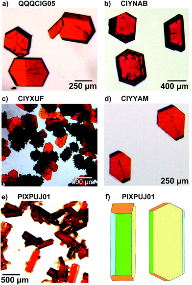 | ||
Fig. 15 (a–d) Experimental morphologies for crystals of rubrene derivatives grown by vacuum sublimation. In (e) are shown crystals of the thienyl derivative grown from hexane/ethyl acetate 9![[thin space (1/6-em)]](https://www.rsc.org/images/entities/char_2009.gif) : :![[thin space (1/6-em)]](https://www.rsc.org/images/entities/char_2009.gif) 1 vol/vol. (f) sketch of the observed crystal morphology in (e) using the color coding of Fig. 14. Crystalline needles shown in (c) belong to a concomitant triclinic polymorph.50 1 vol/vol. (f) sketch of the observed crystal morphology in (e) using the color coding of Fig. 14. Crystalline needles shown in (c) belong to a concomitant triclinic polymorph.50 | ||
The thienyl-rubrene PIXPUJ01 could not be vacuum crystallized due to its thermal instability. Crystallization from hexane/ethyl acetate 9![[thin space (1/6-em)]](https://www.rsc.org/images/entities/char_2009.gif) :
:![[thin space (1/6-em)]](https://www.rsc.org/images/entities/char_2009.gif) 1 vol/vol leads to [010] elongated crystals with {100}, {10
1 vol/vol leads to [010] elongated crystals with {100}, {10![[2 with combining macron]](https://www.rsc.org/images/entities/char_0032_0304.gif) } and {011} bounding faces. The influence of the solvent mixture and of several byproducts in the final reaction mixture17 acting as impurities are likely responsible for the modification of the crystal morphology. It is worth mentioning that the monoclinic polymorph of di-p-nitrophenylrubrene CIYNAB has been obtained also by very slow isothermal evaporation of an acetone solution with a morphology indistinguishable from that of Fig. 15b. Faster isothermal evaporation of an acetone solutions of di-p-nitrophenylrubrene afforded a solvated species.50 Examples of the effect of solvent nature upon crystal morphology of pristine rubrene can be found in previous work.51,52
} and {011} bounding faces. The influence of the solvent mixture and of several byproducts in the final reaction mixture17 acting as impurities are likely responsible for the modification of the crystal morphology. It is worth mentioning that the monoclinic polymorph of di-p-nitrophenylrubrene CIYNAB has been obtained also by very slow isothermal evaporation of an acetone solution with a morphology indistinguishable from that of Fig. 15b. Faster isothermal evaporation of an acetone solutions of di-p-nitrophenylrubrene afforded a solvated species.50 Examples of the effect of solvent nature upon crystal morphology of pristine rubrene can be found in previous work.51,52
Summary and final remarks
The available crystallography of rubrene materials has been thoroughly reviewed through deposited X-ray determinations, with the aim of establishing a database of fully reliable crystal structures for theoretical studies. The final result was 33 crystal structures double-checked and normalized with respect to hydrogen-atom positions. All the structures include at least one highly stabilizing molecular pair at a center-of-mass distance of 7–8 Å. The database has been analyzed systematically in terms of structural patterns, with a statistical assessment of the frequency of the main aggregation modes. The slipped-cofacial pairing arrangement is almost ubiquitous, being an obvious coupling (“encroaching”) mode given the irregular molecular shape: this mode permits as much tetracene stacking as possible, indispensable for promoting transport. Its propagation in three-dimensional monoclinic networks often goes through the herringbone pattern, of which two variants have been found, one with shortest translation of 7 Å and tetracene inter-planar angle of 60°, and another with shortest translation of 9 Å and highly variable inter-planar angles. Triclinic structures occur with a perforce parallel arrangement of tetracene cores. These common features are not exclusive, as examples of other close pairing and propagation modes have been found. Somewhat unexpectedly, in a few cases even asymmetric pairing of two molecules in Z′ = 2 crystals leads to very high stabilization without intervention of a symmetry operation. Systematization has proceeded to a point, but only sparse clues have appeared as concerns the dependence of packing modes on substituent chemistry, or on molecular conformation (twisting of the tetracene core).Isostructurality has been analyzed by lattice energy calculations and plots of pairing energy profiles, that reveal at a glance similarities and differences in crystal packing over and above a sometimes dubious comparison of cell parameters. A classic example of isostructurality (and isomorphism) appears for three para-substituted (NO2, CF3 and CN) lateral phenyls, and also surprisingly, a di-thiophene derivative. Three triclinic structures, the parent hydrocarbon, the di-p-nitrophenyl derivative, and a dipyridine derivative, are also isomorphous. These findings suggest that crystal packing is a driving force that supersedes or at least attenuates the effects of chemical substitution.
Polymorphism is only sparse in the database, the scarce solubility and stability of rubrenes hampering or preventing extensive screenings. Our survey accepts only three cases of undisputable determination: first, the parent hydrocarbon, for which three well determined polymorphs have been deposited, so many presumably because it has been subjected to wider screening efforts; then, the perfluoro compound with two polymorphs, presumably for the same reasons; although our energy calculations strongly suggest that one polymorph is metastable or even unstable.
We report here the structure of a newly found polymorph of the di-p-nitro derivative, obtained after substantial screening: the improved stability toward oxidation of di-p-nitrophenylrubrene allowed crystallization attempts with different solvents affording the monoclinic polymorph or acetone and dichloromethane solvate crystals. The triclinic polymorph has been obtained only by vacuum sublimation with a steeper temperature gradient compared to conditions leading to the monoclinic structure. The comparison of polymorphic energy profiles provides an immediate and univocal proof of the diversity of the crystal packings, the prerequisite for acceptance of a polymorph as a legitimate new material.
A thorough analysis of crystal structures in terms of interaction energies is also fruitful for reliable modeling of crystal morphologies.28 Good agreement between calculated and observed crystal morphologies has been demonstrated for acenes40,41 and oligothiophenes.42 This approach naturally provides the crystallographic planes and cuts of surfaces reasonably involved in crystal growth processes. Other simpler (and much less demanding) techniques generally provide heavily biased and/or uncomplete results.40 The growth morphologies obtained in the present study from analysis of crystal structures via the PBC approach compare satisfactorily with crystals grown from the vapor. The only morphology differing appreciably from the predicted one involves the thienyl derivative. In that case a complex mixture of byproducts (separated with difficulty and incompletely from the main product with column chromatography followed by fractional crystallizations) with molecular structures related to the thienyl rubrene17 are likely responsible for modification of the crystal morphology.53
The presence of strongly bound (h00) layers in all five analyzed structures arises from the slipped-cofacial arrangement adopted with only small differences. This feature is associated with the strongest periodic bond chains and determines low values for surface energy and attachment energy, respectively determining the equilibrium and growth shape. The similarities in the overall pattern of intermolecular bonds and, hence, of periodic bond chains explain the limited variations of observed growth morphologies. These correspond to crystals defined by Hartman's flat faces characterized by the lowest attachment energies among all possible crystallographic planes. Finally, as already noted in other organic semiconductor crystals, growth morphologies are more anisotropic than equilibrium ones,40–42 with different degrees of tabular shapes where the largest surfaces comprise structural layers based on the slipped-cofacial motif. The corresponding low values for the attachment energy make these crystallographic planes dominate the crystal morphology.
Finally, the insights provided by CLP and PIXEL intermolecular potentials show promise for access to lattice energies and morphology prediction without recourse to computationally intensive quantum chemical methods. As concerns the materials science involved, in general, from our overview it looks like sensitive spots of the driving forces for rubrene packing are the 4-substitution sites at the lateral rings, with substituents of moderate steric bulk. Peripheral substitution at the tetracene core seems to be less influential in steering the packing and hence the physical properties. Our survey provides a structural background that could generate new ideas directing the synthesis of new derivatives and provide hints for the development of enhanced transport properties.
Author contributions
Massimo Moret (principal investigator) provided the framework for the research project and is mainly responsible for the PBC part. Angelo Gavezzotti developed the methodology for the crystallographic database studies. Both authors concur in the preparation and presentation of the manuscript.Conflicts of interest
There are no conflicts to declare.Acknowledgements
Dr Stefano Bergantin is acknowledged for crystal growth, X-ray data collection and structure refinement of the triclinic polymorph of 5,11-bis(4-nitrophenyl)-6,12-diphenyltetracene.Notes and references
- J. E. Anthony, Angew. Chem., Int. Ed., 2007, 46, 2–34 CrossRef.
- A. Yassar, Polym. Sci., Ser. C, 2014, 56, 4–19 CrossRef CAS.
- V. Podzorov, V. M. Pudalov and M. E. Gershenson, Appl. Phys. Lett., 2003, 82, 1739–1741 CrossRef CAS.
- V. Podzorov, S. E. Sysoev, E. Loginova, V. M. Pudalov and M. E. Gershenson, Appl. Phys. Lett., 2003, 82, 3504–3506 CrossRef.
- M. L. Clapham, E. C. Murphy and C. J. Douglas, Synthesis, 2021, 461–474 CAS.
- T. K. Mullenbach, K. A. McGarry, W. A. Luhman, C. J. Douglas and R. J. Holmes, Adv. Mater., 2013, 25, 3689–3693 CrossRef CAS PubMed.
- D. A. da Silva Filho, E. G. Kim and J. L. Brédas, Adv. Mater., 2005, 17, 1072–1076 CrossRef CAS.
- M. D. Curtis, J. Cao and J. W. Kampf, J. Am. Chem. Soc., 2004, 126, 4318–4328 CrossRef CAS PubMed.
- C. Janiak, J. Chem. Soc., Dalton Trans., 2000, 3885–3896 RSC.
- V. C. Sundar, J. Zaumseil, V. Podzorov, E. Menard, R. L. Willett, T. Someya, M. E. Gershenson and J. A. Rogers, Science, 2004, 303, 1644–1646 CrossRef CAS PubMed.
- J. L. Brédas, J. P. Calbert, D. A. da Silva Filho and J. Cornil, Proc. Natl. Acad. Sci. U. S. A., 2002, 99, 5804–5809 CrossRef PubMed.
- E. Fumagalli, L. Raimondo, L. Silvestri, M. Moret, A. Sassella and M. Campione, Chem. Mater., 2011, 23, 3246–3253 CrossRef CAS.
- S. Bergantin and M. Moret, Cryst. Growth Des., 2012, 12, 6035–6041 CrossRef CAS.
- D. Braga, A. Jaafari, L. Miozzo, M. Moret, S. Rizzato, A. Papagni and A. Yassar, Eur. J. Org. Chem., 2011, 4160–4169 CrossRef CAS.
- Y. Sakamoto and T. Suzuki, J. Org. Chem., 2017, 82, 8111–8116 CrossRef CAS PubMed.
- K. A. McGarry, W. Xie, C. Sutton, C. Risko, Y. Wu, V. G. Young, J. L. Brédas, C. D. Frisbie and C. J. Douglas, Chem. Mater., 2013, 25, 2254–2263 CrossRef CAS.
- S. Uttiya, L. Miozzo, E. M. Fumagalli, S. Bergantin, R. Ruffo, M. Parravicini, A. Papagni, M. Moret and A. Sassella, J. Mater. Chem. C, 2014, 2, 4147–4155 RSC.
- C. Sutton, M. S. Marshall, C. D. Sherrill, C. Risko and J. L. Brédas, J. Am. Chem. Soc., 2015, 137, 8775–8782 CrossRef CAS PubMed.
- D. Käfer, L. Ruppel, G. Witte and C. Wöll, Phys. Rev. Lett., 2005, 95, 166602 CrossRef PubMed.
- A. S. Paraskar, A. R. Reddy, A. Patra, Y. H. Wijsboom, O. Gidron, L. J. W. Shimon, G. Leitus and M. Bendikov, Chem. – Eur. J., 2008, 14, 10639–10647 CrossRef CAS PubMed.
- S. Bergantin, M. Moret, G. Buth and D. P. A. Fabbiani, J. Phys. Chem. C, 2014, 118, 13476–13483 CrossRef CAS.
- O. D. Jurchescu, A. Meetsma and T. T. Palstra, Acta Crystallogr., Sect. B, 2006, 62, 330–334 CrossRef PubMed.
- T. Matsukawa, M. Yoshimura, K. Sasai, M. Uchiyama, M. Yamagishi, Y. Tominari, Y. Takahashi, J. Takeya, Y. Kitaoka, Y. Mori and T. Sasaki, J. Cryst. Growth, 2010, 312, 310–313 CrossRef CAS.
- L. Huang, Q. Liao, Q. Shi, H. Fu, J. Ma and J. Yao, J. Mater. Chem., 2010, 20, 159–166 RSC.
- W. A. Ogden, S. Ghosh, M. J. Bruzek, K. A. McGarry, L. Balhorn, V. Young, L. J. Purvis, S. E. Wegwerth, Z. Zhang, N. A. Serratore, C. J. Cramer, L. Gagliardi and C. J. Douglas, Cryst. Growth Des., 2017, 17, 643–658 CrossRef CAS.
- C. Sutton, N. R. Tummala, D. Beljonne and J. L. Brédas, Chem. Mater., 2017, 29, 2777–2787 CrossRef CAS.
- M. Mamada, H. Katagiri, T. Sakanoue and S. Tokito, Cryst. Growth Des., 2015, 15, 442–448 CrossRef CAS.
- P. Hartman and W. G. Perdok, Acta Crystallogr., 1955, 8, 49–52 CrossRef.
- P. Hartman and W. G. Perdok, Acta Crystallogr., 1955, 8, 521–524 CrossRef CAS.
- P. Hartman and W. G. Perdok, Acta Crystallogr., 1955, 8, 525–529 CrossRef CAS.
- C. R. Groom and F. H. Allen, Angew. Chem., Int. Ed., 2014, 53, 662–671 CrossRef CAS PubMed.
- A. Gavezzotti, New J. Chem., 2011, 35, 1360–1368 RSC.
- A. Gavezzotti, L. Lo Presti and S. Rizzato, CrystEngComm, 2020, 22, 7350–7360 RSC.
- A. Gavezzotti, Mol. Phys., 2008, 106, 1473–1485 CrossRef CAS , A. J. Stone Special Issue.
- J. Bernstein, J. D. Dunitz and A. Gavezzotti, Cryst. Growth Des., 2008, 8, 2011–2018 CrossRef CAS.
- C. Greenwell and G. J. O. Beran, J. Mater. Chem. C, 2021, 9, 2848–2857 RSC.
- P. Hartman, in Morphology of Crystals, ed. I. Sunagawa, Terra Scientific Publishing Company, Tokyo, 1997, pp. 269–319 Search PubMed.
- P. Hartman and P. Bennema, J. Cryst. Growth, 1980, 49, 145–156 CrossRef CAS.
- P. Hartman and H.-K. Chan, Pharm. Res., 1993, 10, 1052–1058 CrossRef CAS PubMed.
- F. R. Massaro, M. Moret, M. Bruno, M. Rubbo and D. Aquilano, Cryst. Growth Des., 2011, 11, 4639–4646 CrossRef CAS.
- F. R. Massaro, M. Moret, M. Bruno and D. Aquilano, Cryst. Growth Des., 2012, 12, 982–989 CrossRef CAS.
- F. R. Massaro, M. Moret, M. Bruno and D. Aquilano, Cryst. Growth Des., 2013, 13, 1334–1341 CrossRef CAS.
- C. F. R. A. C. Lima, J. C. S. Costa, L. M. S. S. Lima, A. Melo, A. N. M. S. Silva and L. M. N. B. F. Santos, ChemistrySelect, 2017, 2, 1759–1769 CrossRef CAS.
- H. Morisaki, T. Koretsune, C. Hotta, J. Takeya, T. Kimura and Y. Wakabayashi, Nat. Commun., 2014, 5, 5400 CrossRef CAS PubMed.
- R. Kern, in Morphology of Crystals, ed. I. Sunagawa, Terra Scientfic Publishing Company, Tokyo, 1997, pp. 77–206 Search PubMed.
- B. D. Chapman, A. Checco, R. Pindak, T. Siegrist and C. Kloc, J. Cryst. Growth, 2006, 290, 479–484 CrossRef CAS.
- T. Minato, H. Aoki, H. Fukidome, T. Wagner and K. Itaya, Appl. Phys. Lett., 2009, 95, 093302 CrossRef.
- M. El Helou, O. Medenbach and G. Witte, Cryst. Growth Des., 2010, 10, 3496–3501 CrossRef CAS.
- D. Käfer and G. Witte, Phys. Chem. Chem. Phys., 2007, 7, 2850–2853 RSC.
- S. Bergantin, Organic semiconductor rubrene: crystal chemistry of derivatives and high-pressure polymorphism, PhD thesis in Materials Science, Università di Milano-Bicocca, 2014.
- T. Matsukawa, Y. Takahashi, T. Tokiyama, K. Sasai, Y. Murai, N. Hirota, Y. Tominari, N. Mino, M. Yoshimura, M. Abe, J. Takeya, Y. Kitaoka, Y. Mori, S. Morita and T. Sasaki, Jpn. J. Appl. Phys., 2008, 47, 8950–8954 CrossRef CAS.
- L. Carman, H. P. Martinez, L. Voss, S. Hunter, P. Beck, N. Zaitseva, S. A. Payne, P. Irkhin, H. H. Choi and V. Pozdorov, IEEE Trans. Nucl. Sci., 2017, 64, 781–788 CAS.
- K. Sangwal, Additives and crystallization processes, John Wiley and Sons, Chichester, 2007 Search PubMed.
Footnote |
| † Electronic supplementary information (ESI) available: An Appendix on crystallographic terminology, more crystal packing and aggregation diagrams as mentioned in the text; numerical detail of the partitioned Coulombic-dispersion energies and comparison of force fields, energy crystal graphs for PBC modeling of crystal morphologies. Deposition number 2149694 contains single crystal X-ray data of the triclinic polymorph of 5,11-bis(4-nitrophenyl)-6,12-diphenyltetracene (provisionally called here CIYNAB01). CCDC 2149694. For ESI and crystallographic data in CIF or other electronic format see DOI: 10.1039/d2nj00861k |
| This journal is © The Royal Society of Chemistry and the Centre National de la Recherche Scientifique 2022 |

