
 Open Access Article
 This Open Access Article is licensed under a Creative Commons Attribution-Non Commercial 3.0 Unported Licence
Experimental evidence for the molecular molybdenum fluorides MoF to MoF6: a matrix isolation and DFT investigation†
Ahmed K.
Sakr
 a,
Howard V.
Snelling
b and
Nigel A.
Young
*a
a,
Howard V.
Snelling
b and
Nigel A.
Young
*a
aDepartment of Chemistry and Biochemistry, The University of Hull, Kingston upon Hull, HU6 7RX, UK. E-mail: N.A.Young@hull.ac.uk
bDepartment of Physics and Mathematics, The University of Hull, Kingston upon Hull, HU6 7RX, UK
First published on 25th April 2022
Abstract
All of the molecular molybdenum fluorides, MoF to MoF6, have been synthesised from the reaction of thermally evaporated molybdenum atoms with fluorine molecules and atoms, trapped in argon matrices, and characterised by matrix isolation IR spectroscopy in conjunction with DFT calculations. This includes the first spectroscopic characterisation of MoF and MoF2, the latter of which is very bent with a bond angle of ca. 133°, the reassignment of the IR spectral data for trigonal planar MoF3, the observation of tetrahedral MoF4, the assignment of new features to MoF5 which displays a Jahn-Teller distorted trigonal bipyramidal structure, and octahedral MoF6. When the reaction of fluorine molecules and heated molybdenum is allowed to take place, MoF6, MoF4 and (MoF5)3 are observed.
Introduction
Molybdenum hexafluoride is commonly used in CVD processes1–5 and since the first report of its preparation in 1907![[thin space (1/6-em)]](https://www.rsc.org/images/entities/char_2009.gif) 6 its vibrational spectra have been widely studied in the gas phase,7–14 noble gas solutions,15 solid noble gas solutions,16 and solid cryogenic matrices.17–23 Solid state structures have been obtained from X-ray powder diffraction,24,25 single crystal X-ray diffraction,26 low temperature Mo K-edge EXAFS,27 as well as vapour phase structures from gas phase electron diffraction.28,29 All of these techniques indicate that MoF6 is octahedral in both the solid state and vapour phases.30 However, due to the presence of low lying trigonal prismatic excited states there are claims that it should be regarded as non-rigid.31 MoF5, particularly in the solid state, has recently been comprehensively reviewed.32 Mass spectrometry of the vapours above heated MoF5 showed that the vapour composition is complex and is mainly comprised of trimers,33–37 with negligible proportions of monomers33,34 but with some evidence for tetramers37 and pentamers.35 Thermal cracking of the saturated vapours at 500 K can yield MoF5 monomers, and a combined electron diffraction and mass spectrometric investigation showed that monomeric MoF5 has C2v symmetry due to a Jahn-Teller distortion.36 Mass spectrometry of the vapour above heated MoF4 indicated the presence of MoF5 molecules.38 Combined electron diffraction and mass spectrometry of the saturated vapours above MoF3 at 943 K revealed the vapour composition as MoF4 (78.5%) and MoF5 (21.5%), and that MoF4 is tetrahedral.39 Previous reports had indicated that the sublimation of MoF3 resulted in disproportionation to give Mo(s), MoF4(g) and MoF5(g).40 The MoF4 and MoF5 vapours above heated MoF3 were also investigated by combined electron diffraction and mass spectrometry, and by removing the MoF5 contribution, the structure of MoF4 was confirmed as tetrahedral.36 There appears to be no experimental data available for molecular MoF2 or MoF other than a high temperature mass spectrometry thermochemical investigation,41 and that for MoF3 has been contested.42
6 its vibrational spectra have been widely studied in the gas phase,7–14 noble gas solutions,15 solid noble gas solutions,16 and solid cryogenic matrices.17–23 Solid state structures have been obtained from X-ray powder diffraction,24,25 single crystal X-ray diffraction,26 low temperature Mo K-edge EXAFS,27 as well as vapour phase structures from gas phase electron diffraction.28,29 All of these techniques indicate that MoF6 is octahedral in both the solid state and vapour phases.30 However, due to the presence of low lying trigonal prismatic excited states there are claims that it should be regarded as non-rigid.31 MoF5, particularly in the solid state, has recently been comprehensively reviewed.32 Mass spectrometry of the vapours above heated MoF5 showed that the vapour composition is complex and is mainly comprised of trimers,33–37 with negligible proportions of monomers33,34 but with some evidence for tetramers37 and pentamers.35 Thermal cracking of the saturated vapours at 500 K can yield MoF5 monomers, and a combined electron diffraction and mass spectrometric investigation showed that monomeric MoF5 has C2v symmetry due to a Jahn-Teller distortion.36 Mass spectrometry of the vapour above heated MoF4 indicated the presence of MoF5 molecules.38 Combined electron diffraction and mass spectrometry of the saturated vapours above MoF3 at 943 K revealed the vapour composition as MoF4 (78.5%) and MoF5 (21.5%), and that MoF4 is tetrahedral.39 Previous reports had indicated that the sublimation of MoF3 resulted in disproportionation to give Mo(s), MoF4(g) and MoF5(g).40 The MoF4 and MoF5 vapours above heated MoF3 were also investigated by combined electron diffraction and mass spectrometry, and by removing the MoF5 contribution, the structure of MoF4 was confirmed as tetrahedral.36 There appears to be no experimental data available for molecular MoF2 or MoF other than a high temperature mass spectrometry thermochemical investigation,41 and that for MoF3 has been contested.42
Some of the molecular molybdenum fluorides have been studied by matrix isolation techniques. The results for MoF6 are unremarkable,17–23 and the observation of the νMo-F T1u mode in the infrared spectrum of MoF6 in solid argon at 737.7 cm−1,19,20 735 cm−1,23 or 736 and 737 cm−121,22 are in excellent agreement with the vapour phase values of 742 cm−1,8 or 741 cm−1.7,9 Molybdenum has seven naturally occurring isotopes and molybdenum isotopic structure has been observed in argon matrices with bands at 743.5 cm−1 and 733.5 cm−1 assigned to 92MoF6 and 100MoF6, respectively.19,20 This is in good agreement with the vapour phase values of isotopically enriched molybdenum 92MoF6 at 747.2 cm−1 and 100MoF6 at 739.3 cm−1.12 The matrix data on the lower valent MoF5, MoF4 and MoF3 species is not unambiguous, and there are no experimental data available for MoF2 or MoF.
The initial argon matrix investigation of the lower fluorides by Acquista and Abramowitz used double boiler Knudsen cell thermal cracking of the vapours above heated MoF5.23 They assigned IR bands at 713 and 683 cm−1 to the E′ and  stretching modes of monomeric, D3h, MoF5, with bands at 768, 716 and 704 cm−1 assigned to polymeric species. A weak band at 733 cm−1 was tentatively assigned to MoF4. These observations, especially the assignments for MoF5 and MoF4, have been called into question by subsequent reports. The first of these used the photolysis of MoF6 in an argon matrix to yield MoF5 monomers with a relatively intense νMo–F IR band at 693.5 cm−1 and a much weaker band at 658.0 cm−1.19,20 From comparison with UF5 data43 it was thought that a square based pyramidal geometry, rather than trigonal bipyramidal, was more justified.19,20 A third weak band observed at 674 cm−1 was tentatively assigned to a νMo–F mode of MoF4, resulting from the subsequent photolysis of MoF5. They also claimed that the band at 713 cm−1 assigned to MoF5 in the previous report23 was in fact due to MoOF4 and that the band at 683 cm−1 was due to polymeric species.19,20 More recent reports indicate that argon matrix isolated MoOF4 has IR bands at 1045 (νMo
![[double bond, length as m-dash]](https://www.rsc.org/images/entities/char_e001.gif) O) cm−1 and 719 (νMo–F) cm−1.44
O) cm−1 and 719 (νMo–F) cm−1.44
A matrix IR investigation by Osin et al. used the reaction of F2/Ar gas mixtures passed over heated molybdenum at different temperatures and flow rates with the products trapped in F2/Ar matrices at cryogenic temperatures to identify the different species.21,22 It should be noted that in these experiments the reactions were occurring on the heated molybdenum surface, with reaction products evaporated from the surface and subsequently trapped in solid argon, rather than with molybdenum atoms. At relatively low temperatures (473 K) the most intense band at 737 cm−1 was assigned to MoF6. Weaker features were observed at 707 cm−1 for high fluorine flow rates and at 712 cm−1, with a poorly resolved shoulder at 707 cm−1 for lower fluorine flow rates. As the temperature of the reactor was increased to 573 K, the MoF6 band at 737 cm−1 band ceased to be the most dominant one and in addition to the bands at 712 and 707 cm−1 new bands were observed at 934, 903, 819, 768, 719, 704, 692, 523, 384, 326 and 256 cm−1. Heating to 713 K resulted in a sharp decrease in intensity of the 737 cm−1 band, and an increase of intensity of the broad band at 715 cm−1, together with poorly resolved shoulders at 705 and 692 cm−1. On heating the reactor to 813 K, the 737 cm−1 band was completely absent and the most intense bands were at 713 and 694 cm−1, together with a new band at 658 cm−1 and a weaker one at 675 cm−1. Peaks at 768 and 523 cm−1 observed at lower temperatures were only present in the spectra when high fluorine flow rates were used at 813 K, and there were also bands at 1044 and 1022 cm−1. When the reactor temperature was increased to 973 K, the spectra were independent of fluorine flow rate and the most intense band in the spectrum was at 694 cm−1, with other bands at 675 and 658 cm−1. The bands at 715–713 cm−1 in the spectra obtained at lower temperature shifted slightly to 711 cm−1, and in the spectra of the reaction products at 713 K, the band centre shifted with fluorine concentration. The other bands observed at lower reactor temperatures were virtually unobservable apart from the band at 1022 cm−1. When the reactor temperature was increased to 1373 K, there were no appreciable changes in the spectra. At the maximum reactor temperatures, the noteworthy features were the appearance of a band at 633 cm−1, together with a weak shoulder at 647 cm−1 and an increase in the relative intensity of the 675 cm−1 band, together with bands at 560 and 445 cm−1. The 737 cm−1 and 261 cm−1 bands were assigned to MoF6 based on previous work19,20,23 and this was confirmed by the thermal behaviour, where the vapour composition calculations showed that MoF6 is the major vapour phase species until 873 K, after which its concentration drops rapidly. The bands at ca. 707 cm−1 were assigned to WF6, and those at 1015.1 and 689 cm−1 to WOF4 due to tungsten impurities either in the molybdenum, or from the reactor, as analogous tungsten experiments were reported in the same paper. The pair of peaks at 1044 and 713 cm−1 were assigned to MoOF4 based on previous work.44 The bands observed at 768, 715, 704, 692, 522, and 230 cm−1 exhibited identical behaviour to each other and on the basis of the 522 cm−1 band being indicative of a bridging Mo–F–Mo feature, these were assigned to (MoF5)3. The 522 cm−1 bridging band is broader than the terminal bands, and about half the peak height of the 768 cm−1 band, and about a sixth of the peak height of the 715 cm−1 peak. The first three bands at 768, 715, 704 cm−1 were also observed by Acquista and Abramowitz at 768, 716 and 704 cm−1, which they assigned to polymeric species.23 The peaks at 694 and 658 cm−1 on heating from 813 K to 1123 K had an approximately constant relative intensity of slightly less than 2:1 and were assigned to MoF5, which was in good agreement with the 693.5 cm−1 band and weaker band at 658.0 cm−1 observed by Blinova and Predtechensky following photolysis of MoF6 in an argon matrix.19,20 On the basis of the relative intensity being closer to 4:1 than 3:2 a C4v structure for MoF5 was thought more probable. However, they pointed out that symmetry lowering due to a Jahn-Teller effect was possible. These assignments are in contrast to the assignment of bands at 713 and 683 cm−1 that Acquista and Abramowitz assigned to MoF5.23 Blinova and Predtechensky suggested that the band at 713 cm−1 was due to MoOF4, and that the one at 683 cm−1 was from polymeric species.19,20 Osin et al. assigned the band at 675 cm−1 to tetrahedral MoF4,21,22 in good agreement with the 674 cm−1 proposed by Blinova and Predtechensky,19,20 but not the 733 cm−1 tentatively proposed by Acquista and Abramowitz.23 The weak band at 633 cm−1 was only observed in spectra at high temperatures and was tentatively assigned to D3h MoF3. (The bands observed at 1022 and 384 cm−1 are due to SiF4, and the bands at 934, 903 and 819 cm−1 were observed both in the molybdenum and tungsten fluoride work21,22 as well as analogous work on chromium fluorides45 and remained unassigned.)
More recently, Sliznev and Belova have carried out CASSCF and XMCQDPT2 calculations on MoF3 and MoF4.42 These calculations predict that MoF4 is tetrahedral, and the calculated ω3(T2) mode at 684 cm−1 was in good agreement with the observed values of 674 cm−1,19,20 and 675 cm−1.21,22 However, in the case of D3h MoF3, the calculated value for ω3(E′) was 706 cm−1 compared to the tentative experimental value of 633 cm−1.21,22 Using the difference of 10 cm−1 between the calculated and experimental values of MoF4, Sliznev and Belova predicted that the experimental value for MoF3 should be close to 696 cm−1, and they noted that in the experimental work involving the reaction of F2 and heated Mo there was a band at 694 cm−1, which they commented could be reassigned to MoF3, although this has been previously assigned to MoF5.19–22
Therefore, given the uncertainty in the assignment of the vibrational modes of MoF3, and the lack of any experimental evidence for molecular MoF2 and MoF we report the results of an investigation of the reaction products of thermally evaporated molybdenum atoms and fluorine molecules and atoms trapped in solid argon, together with supporting DFT calculations.
Experimental
The evaporation of molybdenum atoms requires high temperatures, of the order of 2600 K, to obtain a vapour pressure of 1 × 10⁻³ mbar.46,47 To achieve this, filaments were constructed from four 7 cm strands of 0.25 mm diameter molybdenum wire wound together, and mounted in the water cooled copper electrodes shown in Fig. 1, and satisfactory spectra were obtained using ca. 3.5 V and 20 A. The removable copper disc (25 mm diameter, 10 mm thick with 5 mm hole) between the filament and deposition window acts as a radiation shield, collimates the atomic beam, and also restricts reaction between the heated filament and the fluorine in the matrix gas. There was no evidence for the presence of copper fluorides in the matrix.48,49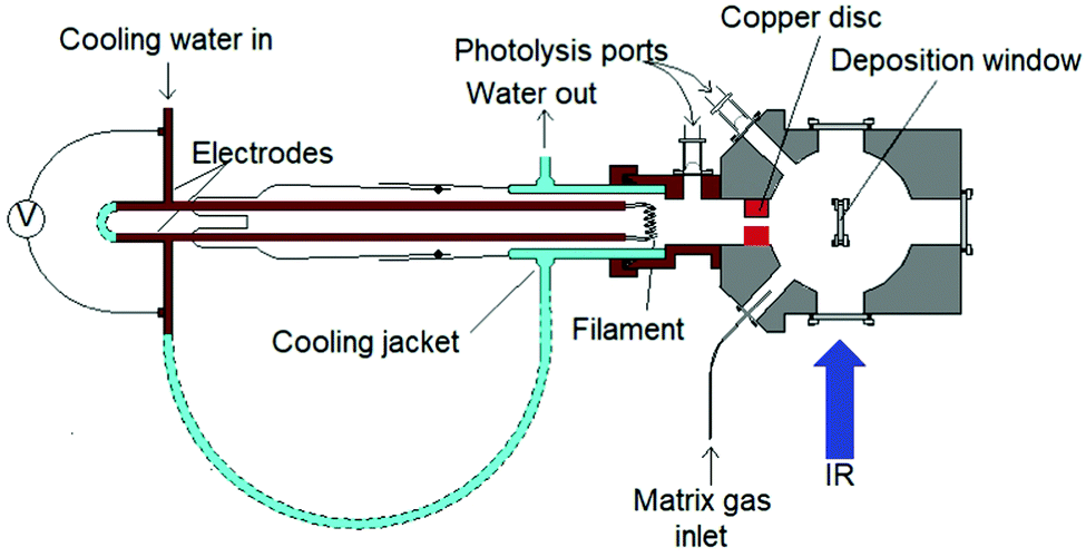 | ||
| Fig. 1 Details of molybdenum atom evaporation source. | ||
It can be assumed that most of the 3.5 V voltage drop occurs across the molybdenum filament due to the connections being large cross-section area water-cooled copper tube and connectors. At the filament's steady state temperature, this gives an approximate resistance of 0.175 Ω. Assuming that the twisted wires have a working, unclamped, heated length of 5 cm, and do not carry current independently and that skin effects are negligible for this D.C. experiment, the resistivity of the hot filament is 69 μΩ cm. The temperature coefficient of resistivity for molybdenum,50 implies that the filament has reached at least 2500 K. At this temperature, the vapour pressure is calculated to be 5.7 × 10⁻² Pa (ca. 0.5 × 10⁻³ mbar) using the data of Nesmeyanov.47 The Hertz-Knudsen equation given below connects the evaporative flux, jvap (atoms per square metre per second) to the vapour pressure, Pvap:
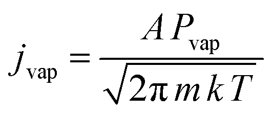
The “sticking coefficient”, A, is taken to be 0.8 which is typical for metals, k is Boltzmann's constant, and m is 1.59 × 10⁻²² g atom−1 for molybdenum. The vapour flux at 2500 K is then 0.8 × 10¹⁹ atoms m−2 s−1. To compare the heated filament flux with other workers that have used laser ablation, the following approach was adopted due to the literature not containing sufficient detail of laser spot sizes and pulse energies. Using the extinction coefficient from the complex refractive index of molybdenum at the laser wavelength, the optical penetration depth and hence the approximate amount of material removed per pulse can be estimated. Typically, neodymium YAG lasers are used with a wavelength of 1064 nm (1.17 eV) and at this photon energy the extinction coefficient is 4.41 (extrapolated between the values for 1.10 eV and 1.20 eV51). The corresponding optical absorption depth is 19.2 nm. If this depth of material is removed per laser pulse, and the repetition rate of the laser is 10 Hz (see, for example ref. 52), then the flux is 1.2 × 10¹⁹ atoms m−2 s−1. Due to the logarithmic dependence of the vapour pressure on temperature, small shifts in temperature can have a large effect on the flux. There are also considerable experimental uncertainties in deriving the fluxes for both the hot filament and laser ablation. Therefore, within this context, the atomic flux for both methods can be seen to be approximately equivalent.
The F2/Ar mixtures were prepared using standard manometric procedures from 10% F2/Ar (Air Liquide) and an all metal vacuum line constructed from 316SS Autoclave Engineer components. As with all fluorine samples there is expected to be trace levels of O2, SiF4, CF4 present. The vacuum line, reservoirs and vacuum chamber were well passivated. The matrix samples were condensed on a CsI window on the cold station of an APD DE-204 cryostat with a base temperature of ca. 10 K. Temperatures were monitored with a silicon diode and a SI-9460 temperature controller. Photolysis was carried with a LOT-Oriel 200 W Hg(Xe) lamp, using visible (400–700 nm) and UV (200–410 nm) filters and broadband irradiation (240–800 nm), with an Oriel liquid light guide (240–800 nm transmission). The IR spectra were recorded with a Bruker EquNox55 FTIR spectrophotometer using a KBr beamsplitter and DTGS detector. A resolution of 2.0 cm−1 was routinely used. Where higher resolution of 1.0 and 0.5 cm−1 was used to identify isotopomeric structure this is noted in the figure captions. In reporting the peak positions, either the value of the most intense component has been used if sufficiently resolved (assumed to be due to the 98Mo isotopomer with 24.13% abundance) or the band centre if not sufficiently resolved. As a result of the variable resolution of the complex isotope pattern, and the amount of fluorine present, small shifts in peak positions between experiments were observed, and the values reported are taken from several data sets. This variation with experimental conditions has also been noted previously in the experiments using the reaction of fluorine with heated molybdenum.21,22
Caution: Fluorine is a powerful oxidiser and toxic. Suitable storage and handling facilities must be used, as well as shielding, protective clothing and face masks. Extensive care must be taken to avoid contact between fluorine, fluorides and oxidisable materials.
DFT calculations were performed at the B3LYP/def2tzvpp level using G09W.53 Net atomic charges and bond orders were calculated from the Gaussian output using the DDEC6 method within Chargemol version 3.5.54–56 Simple valence force field (SVFF) calculations considering only the stretching modes were carried out using SOTONVIB57 or with published F and G matrices.58
Results and discussion
Computational results
Computational calculations were carried out for each molybdenum fluoride using B3LYP/def2tzvpp within G09W53 to identify the minimum energy structure and to help with the assignment of the peaks in the IR spectra. In addition, DDEC6 calculations were carried out to determine net atomic charges and bond orders in these compounds. The calculated geometries and vibrational frequencies are given in Table 1. The recent high level MP2/RECP/VDZ + p calculations by Sliznev and Belova for MoF3 and MoF4 gave Mo–F bond lengths of 1.866 Å and 1.861 Å, respectively.42 As our DFT calculations yield very similar values for the bond lengths, as well as the harmonic frequencies, it is reasonable to assume that the values for the other molybdenum fluorides are satisfactory and therefore the data in Table 1 are the first set of calculations using a consistent computational method for all of the monomeric, molecular, molybdenum fluorides.| Molecular structure | Electronic ground state | Mo–F bond length (Å) | F–Mo–F bond angles | Vibrational modes (cm−1) (IR intensity (km mole−1)) | Force constants (N m−1) | |
|---|---|---|---|---|---|---|
| MoF6 | Octahedral (Oh) | 1A1g | 1.829 | 90° | A 1g 739.0 (0.00) | f r 474.0 |
| T 1u 734.2 (339 × 3) | f rr 24.46 | |||||
| E g 644.2 (0.00 × 2) |
 39.38 39.38 |
|||||
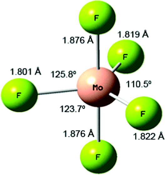
| MoF5 | Distorted trigonal bipyramidal (C1) | 2A | 1.801 (eq.) | 110.5° (eq.) 125.8° (eq.) 123.7° (eq.) 179.4° (ax) | A 761.5 (244) (eqtl asym str) | |
| 1.819 (eq.) | 90.0°, 90.2° | A 726.8 (0.004) (sym str breathing mode) | ||||
| 1.822 (eq.) | 89.7°, 90.0° | A 689.5 (355) (axial asym str) | ||||
| 1.876 (ax) | 90.2°, 89.7° | A 650.0 (228) (eqtl asym str) | ||||
| 1.876 (ax) | A 626.5 (0.066) (asym str breathing mode) | |||||
| MoF4 | Tetrahedral (Td) | 3A2 | 1.860 | 109.47° | A 1 695.2 (0.00) | f r 442.5 |
| T 2 678.8 (186 × 3) | f rr 32.81 | |||||
| MoF3 | Trigonal planar (D3h) |

|
1.861 | 120° | E′ 692.3 (198 × 2) | f r 440.8 |
 662.6 (0.000) 662.6 (0.000) |
f rr 25.30 | |||||
| MoF2 | Bent (C2v) | 5B2 | 1.879 | 132.0° | B 2 665.5 (198) | f r 394.2 |
| A 1 635.0 (59.5) | f rr 32.89 | |||||
| MoF | (C∞v) | 6Σ+ | 1.898 | Σ + 620.1 (148) | f r 360.3 |
Structures
 | ||
| Fig. 2 Calculated (B3LYP/def2tzvpp) structure of MoF5. | ||
The Mulliken charges for MoF5 are Mo1.691 and Fax−0.379, Fax−0.379, Feq−0.318 Feq−0.315 and Feq−0.300. The Mulliken spin densities are 0.870 for Mo and < 0.1 for F. The DDEC6 NACs are Mo3.920 and Fax−0.871, Fax−0.871, Feq−0.734 Feq−0.734 and Feq−712. The DDEC6 bond orders are 0.490 for Mo–Fax and 0.544, 0.541 and 0.532 for Mo–Feq, with a SBO of 2.598. This variation in bond orders is also in line with Rossi and Hoffman's prediction that axial bonds are weaker than equatorial bonds for d1 compounds.64
More recent, detailed CASSCF and MCQDPT2 calculations have investigated the effect of spin–orbit coupling on the stability of the Jahn-Teller distortion of MoF5.66 The 2E′′ D3h ground term is split by a Jahn-Teller distortion into 2A2 and 2B1 states with 2A2 lower in energy by 0.29 kJ mol−1. Spin–orbit coupling splits the 2E′′ D3h ground term into 12E1/2 and 12E3/2 states with the 12E1/2 lower in energy by 8.9 kJ mol−1. Although the spin–orbit coupling quenches the Jahn-Teller distortion, this is not complete and the C2v 12E1/2 spin–orbit state is the global minimum with Mo–Fax of 1.866 Å and Mo–Feq of 1.787 and 1.812 Å and a unique equatorial bond angle of 111.8° all of which are very similar to our values (we could not obtain a C2v structure without negative frequencies). The authors also carried out detailed calculations on the C4v structure and the Berry pseudo-rotation linking the various structures, and as a result concluded that MoF5 exhibits non-rigid intra-molecular rearrangement in its ground state. They took the short Mo–F equatorial bond and Y-shaped distortion to be directed along the z axis, with the x axis as the axial direction and identified the unpaired electron as being in the dxy orbital. When the analogy with the parent D3h structure is maintained with z taken in the axial direction and the short Mo–F equatorial bond and Y-shaped distortion directed along the x axis, we found the unpaired electron in the dyz orbital, which is equivalent to the dxy found above, and with the 4d orbital ordering being dyz < dz2 ≈ dxz < dx2−y2 ≈ dxy.
The vapour above heated MoF5 is complex, and consists principally of trimers with smaller proportions of monomers, tetramers and pentamers.33–37 MoF5 has also been investigated by electron diffraction.36,67–69 The most recent of these reports, utilising a double effusion cell (333 K/551 K) to crack the trimers into monomers36 combined with mass spectral monitoring, identified the monomeric molecular structure as having a C2v ‘T’-shaped geometry due to a Jahn-Teller distortion, with Mo–Feq bond lengths of 1.732(2) and 1.840(2) Å and Mo–Fax of 1.863(2) Å and bond angles of 168.1° (axial) and 122.6° (equatorial). This electron diffraction data has been reanalysed in the light of the recent MCQDPT2 calculations which confirmed the C2v structure.66 Electron diffraction data of the trimers confirmed these as planar and adopting D3h symmetry with F bridges between the MoF6 centres.70,71 The solid state structure of MoF5 has been shown from single crystal X-ray diffraction to be tetrameric with linear bridging fluorine atoms between distorted octahedral molybdenum centres.72
 ground state has d orbital ordering of
  < e′′ < e′. The Mo–F distance of 1.861 Å is in good agreement with the recent calculations of a
  ground state for a trigonal planar geometry with Mo–F bond lengths of 1.838 Å (XMCQDPT2) and 1.866 Å (MP2/RECP/VDZ + p),42 which built on the earlier RHF, MP2 and CASSCF-SOCI calculations.74,75 When spin–orbit interaction was included, two spin–orbit states, 4E1/2 and 4E3/2 separated by 11–14 cm−1 were observed instead of the single
  state.42
The Mulliken charges for MoF3 are Mo1.222 and F−0.407, with spin densities of 2.895 and 0.035, respectively. The DDEC6 NACs are Mo2.194 and F−0.731. The DDEC6 Mo–F bond order was 0.745, with an SBO of 2.235.
There appears to be no structural experimental data for molecular MoF3, but the solid state structure of six-coordinate molybdenum with fluorine bridges is known.76,77
The Mulliken charges for MoF2 are Mo0.862 and F−0.431, with Mulliken spin densities of 3.93 and 0.037, respectively. The DDEC6 NACs are Mo1.317 and F−0.659, and the DDEC6 Mo–F bond order in MoF2 was 0.838, with an SBO of 1.677.
There appears to be no experimental spectroscopic data for MoF2 prior to that presented here.
The MoF Mulliken charges are Mo0.458 and F−0.458, with Mulliken spin densities of 4.949 and 0.0508, respectively. The DDEC6 NACs are Mo0.589 and F−0.589. The DDEC6 calculations yielded a Mo–F bond order of 0.872.
As in the case for MoF2, there appears to be no experimental spectroscopic data for MoF, prior to that presented below.
Vibrational properties
There is no published set of complete calculated vibrational data for all of the molybdenum fluorides using a consistent computational approach to allow for a comparison of the expected relative positions of the IR features. Table 1 contains the data for the stretching modes, the deformation modes are available in Table ESI-1 (ESI†). The calculated value for the T1u IR active Mo–F stretching mode of MoF6 at 734.2 cm−1 in Table 1 is very close to the previous calculated value of 731 cm−159 and the experimental gas phase values of 741 cm−1,9,10 or 742 cm−1,8 and argon matrix values of 737.7 cm−1,19,20 735 cm−1,23 or 736 and 737 cm−121,22 Although there is some experimental IR data for molecular monomeric MoF5,19–23 MoF4,21,22 and MoF3,21,22 Sliznev and Belova have pointed out that there is some uncertainty in the assignments, especially for MoF3.42 For MoF5 there is a recent review, but this focuses on the solid state structures and their vibrational frequencies.32 The calculations for MoF5 in Table 1 indicate three νMo–F modes with appreciable IR activity at 761.5, 689.5 and 650.0 cm−1, with the central one being most intense. The recent SO-MCQDPT2 calculations for the 12E1/2 ground state also predicted three IR active νMo–F modes for MoF5 at 774, 708, and 662 cm−1, with a similar intensity pattern as in our calculations, together with very weak IR modes at 735 cm−1 and 636 cm−1.66 Our calculated harmonic value for the IR active T1uνMo–F mode in MoF4 of 678.8 cm−1 is very close to that of 684 cm−1 calculated (XMCQDPT2) by Sliznev and Belova,42 and our calculated value of the E′ mode of MoF3 of 692.3 cm−1 is close to the recently XMCQDPT2 calculated values of 706 cm−1.42 The calculations indicate that MoF2 is bent with a bond angle of 132° and the ν3 and ν1 bands at 665.5 and 635.0 cm−1 have a relative intensity of ca. 4:1. The single peak for MoF is calculated to be at 620.1 cm−1. Although Siegbahn carried out calculations on MoF91 and MoF2,80 no vibrational data were reported.
The position of the calculated IR active νMo–F stretching modes and their relative intensities in the different molybdenum fluorides, are shown in Fig. 3. In addition to the relative positions and intensities of the IR active νMo–F modes, the Mo isotopic structure in Fig. 3 can also be used to assign the features. The majority of the bands have a similar separation of the seven naturally occurring molybdenum isotopic components, but it should be noted that the MoF2 symmetric stretching mode at 635 cm−1 has a very compressed isotopic structure, and that of MoF is intermediate.
 | ||
| Fig. 3 Calculated (B3LYP/def2tzvpp) infrared spectra of MoFn molecules and their isotope patterns at 0.5 cm−1 full width half maximum. Relative intensities scaled to calculated values. | ||
The SVFF principal (fr) and interaction (frr and  ) force constants determined using the F and G matrix elements58 and the calculated frequencies are also given in Table 1 (those for MoF5 are not included because of its low symmetry, and more details are given in Table ESI-2). For MoF6 these are in very good agreement with those of Claassen93 (who did not appear to update them with their later, more accurate data9,10) and McDowell et al..12 The force constant values of Pistorius94 and Ucun95 for frr are in good agreement with these, but they do not seem to have treated fr and the trans interaction force constant,
  , properly, so whilst their fr +
  values are similar to ours, the individual values are not. These data are summarised in Table ESI-3 (ESI†).
The B3LYP/def2tzvpp calculations predict that the wavenumber value of the IR active mode of MoF3 lies above that of MoF4, and has a similar value to that of the central feature of MoF5, which is contrary to normal expectations. However, the principal force constants, fr, derived from these values increase monotonically from MoF to MoF4 and then MoF6 indicating that if force constant is taken as a measure of bond strength, this does increase with oxidation state. As expected, there is a strong correlation between the stretching force constant and the Mo–F bond-length, and this is demonstrated in the Badger's rule plots96 given in Fig. ESI-1 (ESI†) for both the principal force constant fr and the force constant derived from the totally symmetric stretching mode.
Thermodynamics
The overall (Mo + (n/2)F2 → MoFn) reaction enthalpies calculated at the B3LYP/def2tzvpp level are shown in Fig. 4, together with the experimental data of Hildenbrand based on high temperature mass spectrometry,41 and the NIST-JANAF thermochemical tables data97 which are largely based on Hildenbrand's data.41 To make the data consistent, the experimental data has been offset by the molybdenum enthalpy of sublimation (658.98 kJ mol−1) also taken from the NIST-JANAF data.97 There is good agreement between the calculated and experimental values, and the divergence for the higher fluorides is expected because of the way that small differences propagate in both the experimental and calculated values. It is clear from these data that the formation of MoF6 from molybdenum atoms and fluorine molecules is thermodynamically very favourable provided there is sufficient fluorine present. If fluorine atoms are used then the reactions become more favourable by 76.5 kJ mol−1 as the calculated bond dissociation energy of F2 was calculated to be 152.9 kJ mol−1. This is in very good agreement with the experimental value of 154.56 kJ mol−1.97 (See Forslund and Kaltsoyannis for a description of the challenges in calculating F2.98). The stepwise enthalpies of formation (Mon−1 + (1/2)F2 → MoFn) are also given in Fig. 4, and show the subtle variation in reaction enthalpies not readily identifiable in the overall reaction enthalpy data. Whilst the addition of each additional fluorine is exothermic, this becomes less so after the formation of MoF3. These data are readily converted into the D0 bond dissociation energies (MoFn → MoFn−1 + F) using the F2 dissociation energy, and these data are also shown in Fig. 4 where they are compared with Hildenbrand's experimental data.41 (There are no NIST-JANAF data available as whilst the average bond energy given by dividing the enthalpy of atomisation by the number of Mo–F bonds is available, the bond dissociation energy for the loss of the first fluorine atom in each case is not present in the tabulations97). Siegbahn calculated (MCPF) De binding energies of 420 kJ mol−1 and 466 kJ mol−1 for MoF,91 and MoF2,80 respectively. Cheng et al. calculated (B3LYP/6-311 + +G(df)-Stuttgart-Dresden) De binding energy of 449 kJ mol−1 for MoF.92 Craciun et al. have calculated (B3LYP)/ADZ-PP) the first bond dissociation energy of 360 kJ mol−1 and the average BDE of 446 kJ mol−1 for MoF6.59 The similarity in the trends between our calculated data and Hildenbrand's experimental data41 is striking, the only significant divergence is that Hildenbrand found that the weakest Mo-F bond was in MoF5 (which was also consistent with WF599) whereas our calculations indicate that the lowest value is for MoF6.
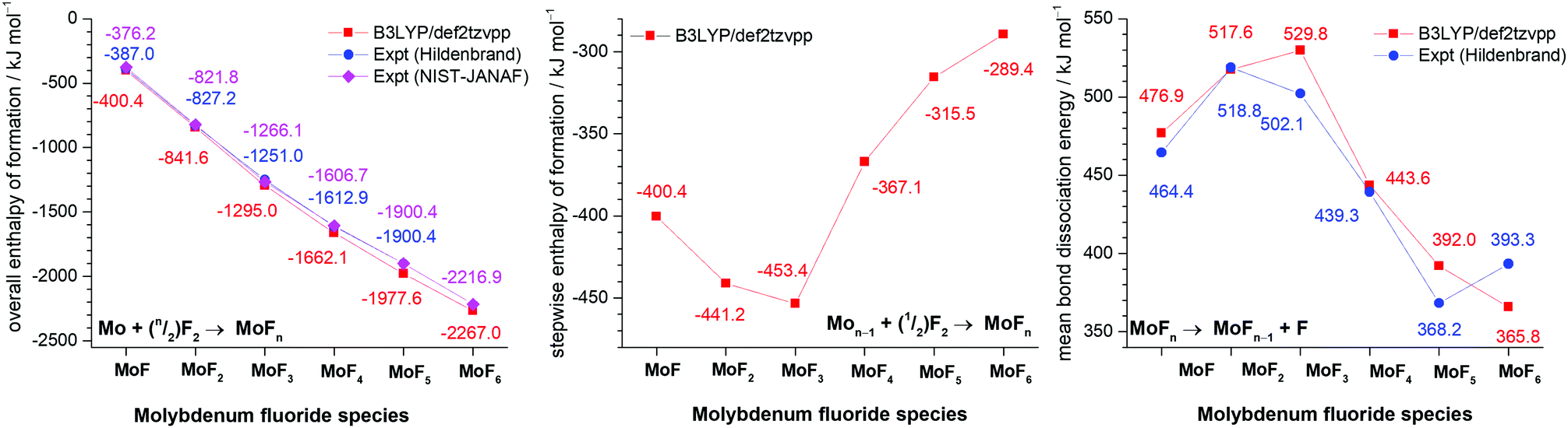 | ||
| Fig. 4 Comparison of B3LYP/def2tzvpp calculated values and experimental values of overall enthalpy of formation (kJ mol−1) (left), stepwise enthalpy of formation (kJ mol−1) (centre) and bond dissociation energy (kJ mol−1) (right) for molybdenum fluorides. | ||
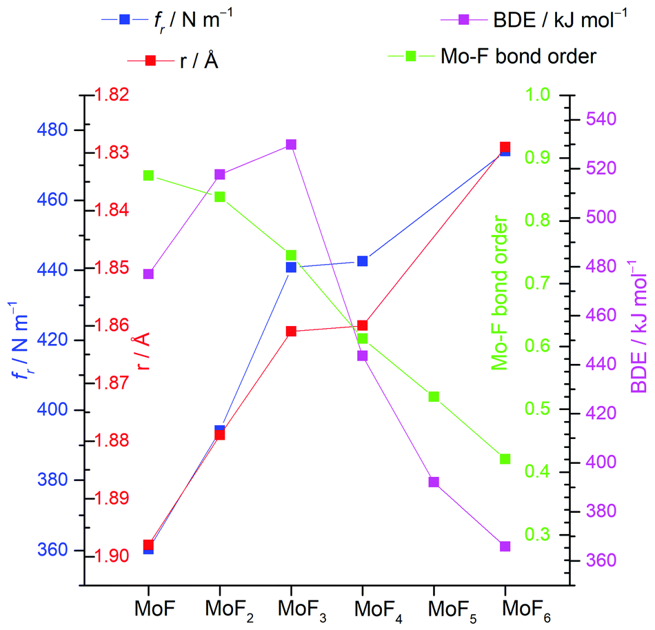
A summary of the trends of bond length, principal force constant fr, first bond dissociation energy and bond order is shown in Fig. 5. As to be expected from the Badger's rule plots (Fig. ESI-1, ESI†) there is a strong correlation between bond length and vibrational frequency for all the molybdenum fluorides. However, this correlation is only mirrored in the bond dissociation energies for MoF to MoF3 and then there is a significant reduction in the bond dissociation energy for MoF4, MoF5 and MoF6. The DDEC6 bond order per Mo–F bond decreases from MoF to MoF6, which correlates well with the bond dissociation energy from MoF3 to MoF6. A recent essay by Kaupp et al. has explored the potential bond-length/bond-strength (BLBS) correlations.100 They pointed out that whilst the force constant and bond-length may be reasonable and correlated proxies for bond-strength, the bond dissociation energy has huge chemical significance as a measure of bond-strength because of its impact on reaction chemistry. They also noted that the bond-length is related to the position of the minimum on the potential energy surface, and the force constant with the curvature at this minimum, but that the bond dissociation energy is related to the depth of the potential energy surface, and is also subject to geometrical changes. They stated that they were not aware of any law that correlates these three parameters.
 | ||
| Fig. 5 Plots of calculated (B3LYP/def2tzvpp) principal force constant fr, Mo-F bond length r, bond dissociation energy (BDE) and DDEC6 bond order for molybdenum fluorides. | ||
Matrix isolation IR spectroscopy results
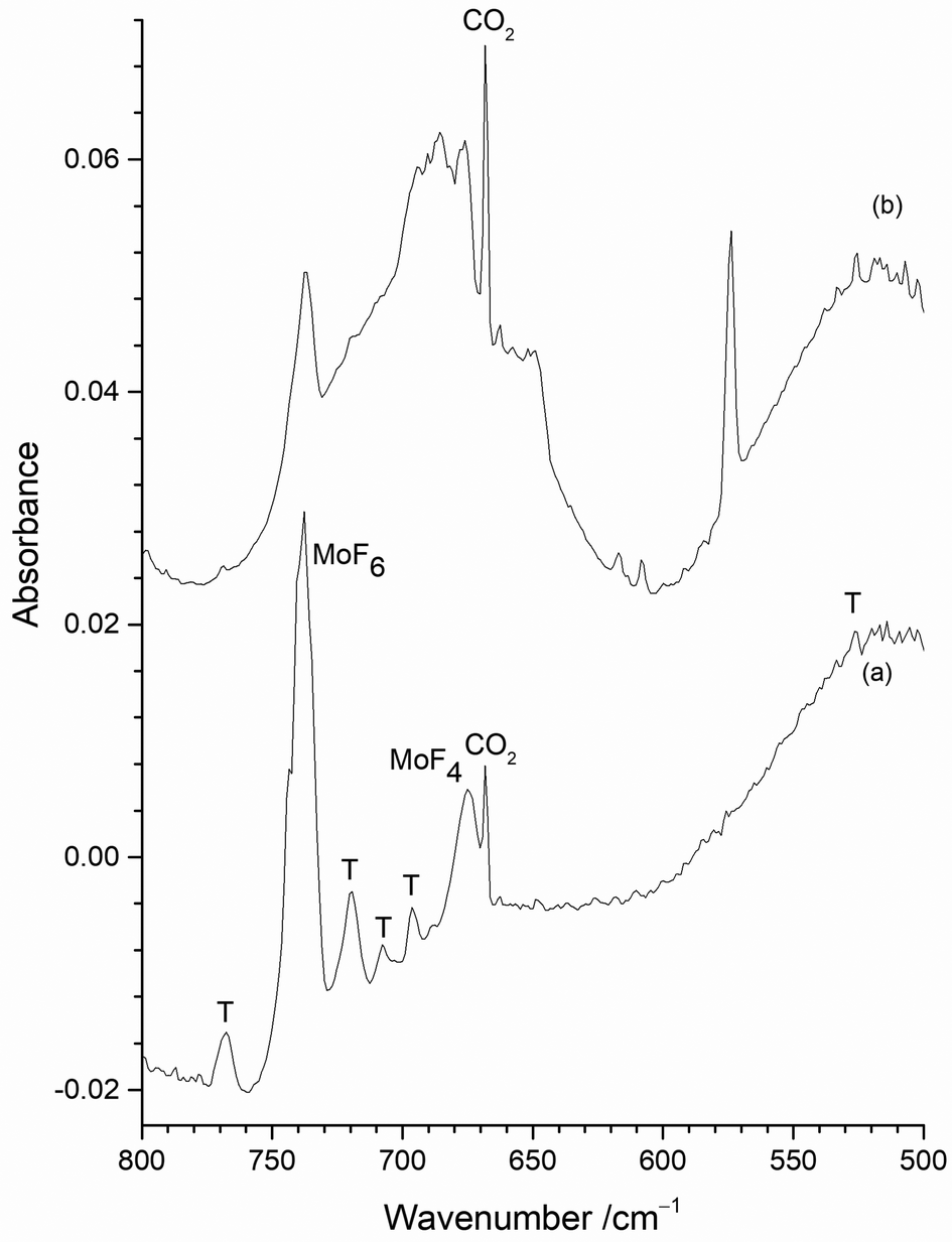 | ||
| Fig. 6 Infrared spectra of reaction products of 1% F2/Ar with heated Mo filament and atomic Mo isolated in 1% F2/Ar matrix (a) with exposed Mo filament; (b) with Mo filament protected by a copper disc. | ||
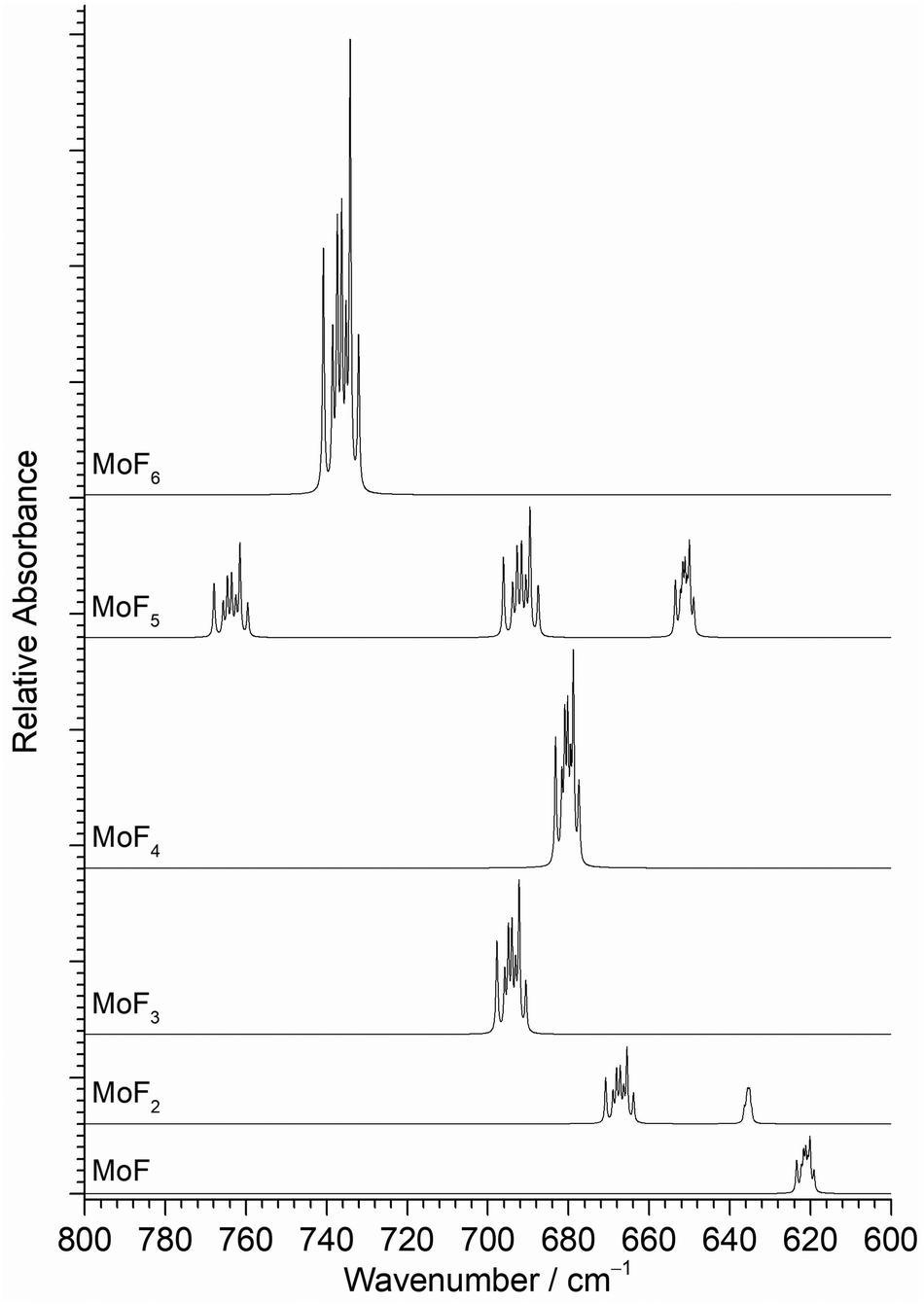
The only clear common band is at 737.8 cm−1 in Fig. 6(a) and 737.2 cm−1 in Fig. 6(b). On the basis of the existing literature data19–22 these features are readily assigned to the T1uνMo–F asymmetric stretching mode of MoF6 in an argon matrix. Whilst some of the peaks between 800 and 660 cm−1 in Fig. 6 appear to be in similar positions in the two spectra there are small, but significant shifts in some of the bands with and without the protective Cu disc present. Some of these bands have been observed in the previous work using the thermal cracking of MoF5,23 the photolysis of MoF6 in argon matrices,19,20 and the reaction of fluorine with a heated molybdenum surface,21,22 and have been assigned to MoF5, (MoF5)3, MoF4 and MoF3. Whilst there is consensus that the bands at 674 to 675 cm−1 are due to MoF4,19–22,42 there is some degree of doubt about the assignment of the features due to monomeric MoF5 and MoF3.
The presence of bands at 767.7, 719.7, 707.5 cm−1 (marked as T) in Fig. 6(a) correspond well with bands at 768, 715, 705 cm−1 previously assigned to MoF5 trimers formed from the reaction of F2 and hot molybdenum,21,22 and the bands at 768, 716 and 704 cm−1 assigned to polymers in work on the thermal cracking of MoF5.23 The band at 696.0 cm−1 could be assigned to monomeric MoF5 (694 cm−1, reaction of F2 with heated molybdenum;21,22 693.5 cm−1, photolysis of MoF623) but there is a tentative assignment to another mode of the MoF5 trimer at 692 cm−1.21,22 The presence of (MoF5)3 in the data collected without the protective copper disc indicates that there is the potential for trapping of the reaction products from the reaction between F2 and the exposed hot Mo filament, as well as with Mo atoms evaporating from the filament.
The features between 660 and 550 cm−1 in the spectrum obtained using a “protected” filament (Fig. 6(b)) have not been observed previously, apart from an unassigned weak peak involving the reaction of laser ablated molybdenum and OF2.52 As the calculations indicate that this region will be associated with the formation of lower valent, monomeric fluorides, from the reaction of Mo atoms and F2 the spectra obtained with the copper disc in place will be considered in detail first, before returning to those recorded without it.
Effects of variation of F2 concentration
Fig. 7 shows the effect on the spectra of varying the F2 concentration when using the Cu disc to protect the heated Mo filament from reacting with the F2. The spectrum with 0.2% F2/Ar (Fig. 7(a)) is dominated by one peak at 573.8 cm−1 (A) with some very weak features at 653.7 cm−1 (C), 647.2 cm−1 (B), 616.7 cm−1 (C′), and 608.3 cm−1 (B′). (The inverse peak at 667 cm−1 is due to gas phase CO2 within the spectrometer compartment, matrix isolated CO2 is at 662 cm−1.) When 0.5% F2/Ar was used (Fig. 7(b)), the A peak at 573.8 cm−1 was also present, but the C′ and B′ features at 616.7 and 608.3 cm−1 were more prominent, together with a broad feature at 650 cm−1 which has overlapping C and B components at 653.7 and 647.2 cm−1. In addition, there were broad features at 676.0 cm−1 (D) and 684.6 cm−1 (E), and only a very weak band at 737.2 cm−1 (G). On increasing the proportion of F2 to 1% (Fig. 7(c)), the biggest difference is the significant growth of the MoF6 peak G at 737.2 cm−1, and an increase in relative intensity of the features at 694.3 cm−1 (F), 684.6 cm−1 (E) and 676.0 cm−1 (D) compared to those between 670 and 630 cm−1, and the growth of a weak peak at 768.9 cm−1 (F′). In the spectrum utilising 2% F2/Ar (Fig. 7(d)), the G peak at 737.2 cm−1 is more intense, and there is a change in the relative intensity of the features between 710 and 670 cm−1 with the central feature at 684.6 cm−1 (E) now significantly less intense than those at 694.3 cm−1 (F) and 676.0 cm−1 (D), indicating that the 694.3, 684.6 and 676.0 cm−1 features are all from different species. Although the 573.8 cm−1A band has reduced in intensity, those between 670 and 630 cm−1 are now also much lower in intensity with increased F2 concentration.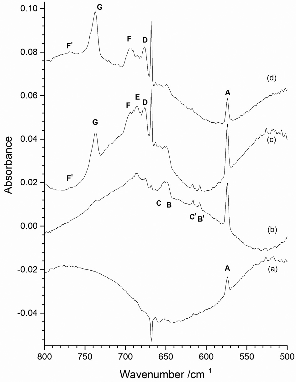 | ||
| Fig. 7 Infrared spectra of reaction products on initial deposition of atomic Mo isolated in (a) 0.2% F2/Ar matrix; (b) 0.5% F2/Ar matrix; (c) 1% F2/Ar matrix; (d) 2% F2/Ar matrix. (All experiments used a Mo filament protected from F2 using the Cu disc). | ||
It would normally be expected that the higher oxidation state fluorides will be formed with higher concentrations of F2 in the argon matrix. The G peak at 737.2 cm−1 can be readily assigned to MoF6 molecules on the basis of previous work.19–23 It is present on deposition in 2% and 1% F2/Ar matrices, is only very weak in 0.5% F2/Ar matrices and is absent in 0.2% F2/Ar matrices. Higher resolution spectra of this band are shown in Fig. ESI-2 (ESI†). Gas phase IR data using isotopically pure samples showed a separation between 92MoF6 and 100MoF6 of 8.1 cm−1 (749.5 to 741.4 cm−1).12 Our calculated values (both B3LYP/def2tzvpp and SVFF) predict that this should be a shift of 8.8 cm−1 from 749.5 to 740.7 cm−1. When the measurement was carried out using laser diode spectroscopy on isotopically pure 92MoF6 and 100MoF6 a shift of 8.146 cm−1 (749.482 to 741.341 cm−1) was observed.14 For MoF6 in a solid xenon solution, the shift from 92MoF6 to 100MoF6 was 8.22 cm−1.16 Previous matrix data did not achieve complete resolution of the Mo isotopes, but a 92MoF6 (743.5 cm−1) to 100MoF6 (733.5 cm−1) shift of 10.0 cm−1 was reported.19,20 Osin et al. also observed Mo isotopic structure at 743.1, 739.8, 736.8 and 733.6 cm−1, but again it was not fully resolved.21,22 Our SVFF calculated shift of 8.8 cm−1 for 92MoF6 to 100MoF6 (743.5 cm−1 to 734.7 cm−1, or 743.1 to 734.4 cm−1) is smaller than the observed shifts, and this is probably due to the presence of matrix sites which are well known for octahedral species such as SF6.101,102 Osin et al. also commented that on the whole their MoF6 isotopic pattern agreed with their calculations for Oh symmetry, but the agreement in splitting values was less satisfactory probably because of matrix effects.21,22 In our spectra (Fig. ESI-2, ESI†) the features in this region were also not fully resolved, especially in the spectra obtained using the “protected” filament, and were observed at 744.0, 740.3, 738.9, 735.8 (sh), 734.4 (sh) and 732.6 (sh) cm−1 in the spectra obtained without the copper disc and at 743.5, 741.7 (sh), 740.7 (sh), 737.4, 735.9 (sh) and 732.4 (sh) in the spectra obtained with the filament protected by the copper disc, in good agreement with the earlier work. The comparison of our experimental spectra and the calculated spectra at different full width half maxima (fwhm) (Fig. ESI-2, ESI†) indicate the difficulties with identifying the bands belonging to the different molybdenum isotopomers, which is made significantly more challenging when matrix sites are also present. However, the presence of molybdenum isotopic structure confirms the assignment of these features to MoF6.
Three IR bands located at 694.3 cm−1 (F), 684.6 cm−1 (E) and 676.0 cm−1 (D) have been observed with different relative intensity for the 2%, 1% and 0.5% F2/Ar matrices (Fig. 7). The 676.0 cm−1 (D) band is present in all three, whereas the relative intensity of the central 684.6 cm−1 band E compared to the 676.0 cm−1 (D) band decreases with increasing F2 concentration, indicating that it belongs to a lower valent fluoride. In contrast, the intensity of the 694.3 cm−1 (F) band increases compared to the 684.6 cm−1 (E) and 676.0 cm−1 (D) bands, with increasing F2 concentration, indicating a higher valent fluoride. The intensity of the 694.3 cm−1 (F) band is also correlated with a weak peak at 768.9 cm−1 (F′). In contrast, these features are not present in an argon matrix doped with a low concentration (0.2%) of F2, as shown in Fig. 7(a). A feature observed at 693.5 cm−1 has been assigned previously to MoF5 formed from the photolysis of MoF6, together with a weak band at 658.0 cm−1 about 40% of the intensity of that at 693.5 cm−1.19,20 In the previous work involving reactions between heated molybdenum and F2, features at 694 cm−1 and 658 cm−1 were also assigned to MoF5.21,22 Features at 675–674 cm−1 have previously been assigned to MoF4 by a number of workers.19–22 The assignment of a band at 633 cm−1 to MoF3 in the work involving the reaction of F2 and heated molybdenum,21,22 has been called into question on the basis of more recent calculations.42 The feature at 573.8 cm−1 (A) is observed for all concentrations of F2/Ar, but its relative intensity to the other features is highest for the lower concentrations of F2 in the argon matrix. The bands at 653.7 cm−1 (C), 647.2 cm−1 (B), 616.7 cm−1 (C′), and 608.3 cm−1 (B′) are observed for all concentrations of F2/Ar matrices, but their relative intensity is lowest in a 2% F2/Ar matrix. Therefore, the A band observed at 573.8 cm−1, together with those labelled C, B, C′, and B′ at 653.7, 647.2, 616.7, and 608.3 cm−1 are most likely due to low valent molybdenum fluoride species. In the following sections detailed analysis of the effects of photolysis and annealing on the samples containing different proportions of F2 is used to assign the peaks to particular species.
Identification of MoF and MoF2
Infrared absorption and difference spectra of the reaction products of Mo atoms with an argon matrix doped with 0.5% F2 and after photolysis and annealing are presented in Fig. 8. On deposition (Fig. 8(a)) the most significant feature is at 573.8 cm−1 (A), with weaker bands at 684.6 cm−1 (E), 676.0 cm−1 (D), 616.7 cm−1 (C′), 608.3 cm−1 (B′), with a broad feature at 650 cm−1 and a very weak band at 737.2 cm−1 (G). After visible photolysis (400–700 nm) (Fig. 8(b)), the only change is a slight reduction in the intensity of the 573.8 cm−1 (A) feature. UV photolysis (240–410 nm) (Fig. 8(c)) resulted in the increase in intensity of the two sharp peaks at 608.3 cm−1 (B′) and 616.7 cm−1 (C′), as well as the broad overlapping feature at 650 cm−1 (which has components at 653.7 cm−1 (C) and 647.2 cm−1 (B)). Broadband photolysis (240–800 nm) (Fig. 8(d)) resulted in a slight growth of the broad feature at 650 cm−1, as well as those at 616.7 cm−1 (C′) and 608.3 cm−1 (B′), and a reduction in the 573.8 cm−1 (A) band. There is also a slight redistribution of intensity of features within the 705–660 cm−1 region. There is no observable change after second visible photolysis (Fig. 8(e)), but annealing results in some significant changes. Annealing to 15 K for 5 min (Fig. 8(f)) results in an increase of the peaks at 737.2 cm−1 (G), 694.3 cm−1 (F) and 676.0 cm−1 (D), and a reduction in intensity of the band at 653.7 cm−1 (C). Further annealing for 5 min at 20 K (Fig. 8(g)) results in a significant increase in intensity of the G peak at 737.2 cm−1, with other increases at 647.2 cm−1 (B) and 608.3 cm−1 (B′), accompanied by a decrease in peaks at 653.7 cm−1 (C) and 616.7 cm−1 (C′) and 573.8 cm−1 (A). The change in relative intensity of the 653.7 cm−1 (C) and 647.2 cm−1 (B) peaks and the 616.7 cm−1 (C′) and 608.3 cm−1 (B′) peaks is most marked in the difference spectra, but it is also clear from the absorption spectra that what appear as closely spaced doublets are converted to singlets by annealing to 20 K. After annealing at 25 K (Fig. 8(h)) there is a significant increase in the G band at 737.2 cm−1, a slight increase in the D band at 676.0 cm−1, together with decrease in the A, 573.8 cm−1 feature, and this is repeated after annealing to 30 K. During the annealing cycle there is a shift in relative intensity in the peaks in the 700–660 cm−1 region, with peak E at 684.6 cm−1 becoming less pronounced than the D band at 676.0 cm−1 and to a lesser extent by a weak feature, F, at 694.3 cm−1 after annealing.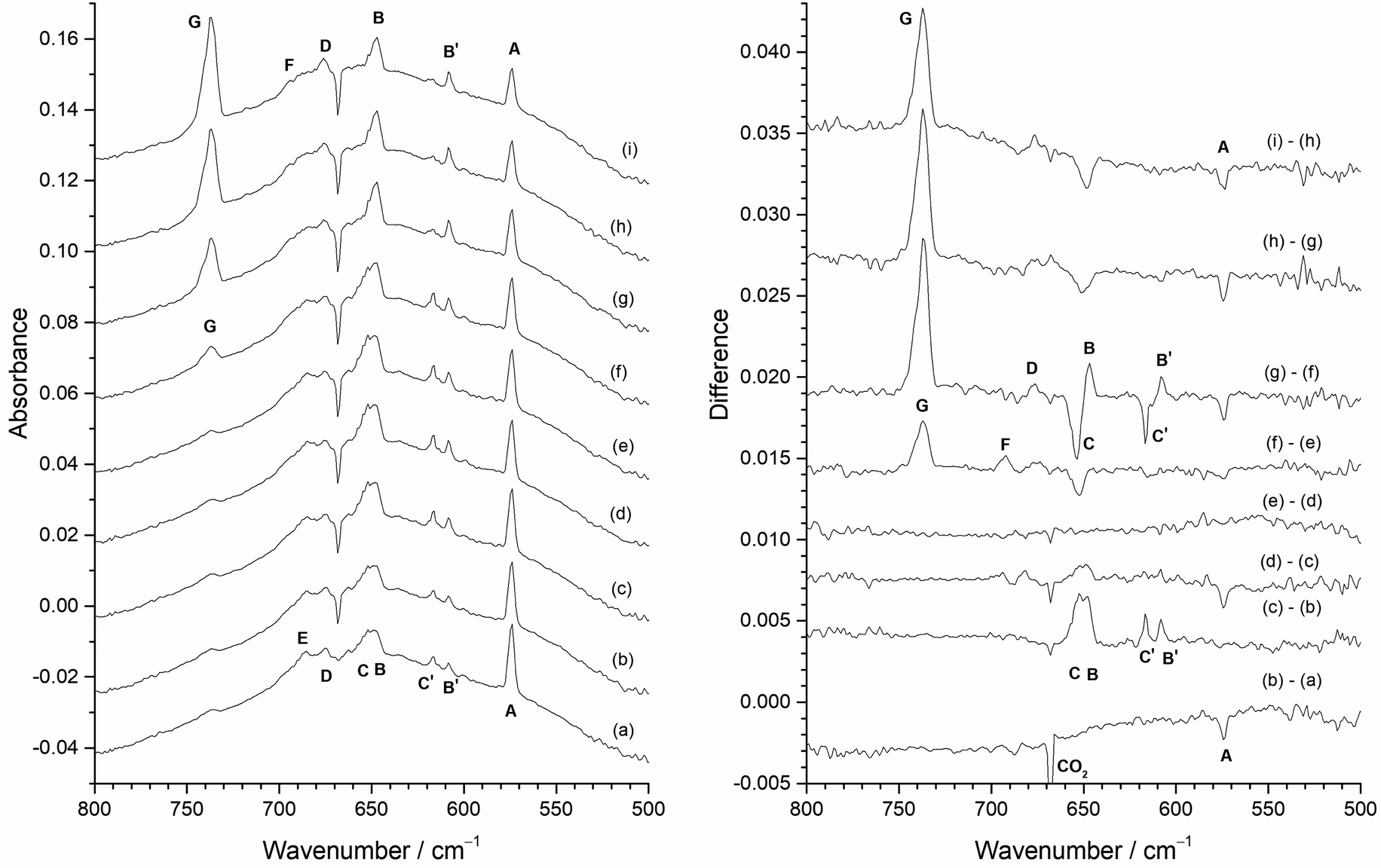 | ||
| Fig. 8 Infrared absorbance (left) and difference (right) spectra of reaction products of atomic Mo in 0.5% F2/Ar matrix with the heated Mo filament protected from F2 using the Cu disc: (a) after deposition; (b) after 10 min visible photolysis (400–700 nm); (c) after 10 min UV photolysis (240–410 nm); (d) after 10 min broadband photolysis (240–800 nm); (e) after further 10 min visible light photolysis (400–700 nm); (f) after 5 min annealing at 15 K; (g) after 5 min annealing at 20 K; (h) after 5 min annealing at 25 K; (i) after 5 min annealing at 30 K. | ||
The results of carrying out the experiment in reverse, i.e. annealing followed by photolysis, are shown in Fig. 9. The spectrum on deposition (Fig. 9(a)) is very similar to that in Fig. 8(a). After annealing to 15 K (Fig. 9(b)) there is a small increase in the MoF6 band G at 737.2 cm−1, a reduction in the A band at 573.8 cm−1, and some slight changes in the other peaks. Annealing to 20 K (Fig. 9(c)) results in a significant increase in the MoF6G band at 737.2 cm−1, and the reversing of intensity of the 653.7 cm−1 (C) and 647.2 cm−1 (B) peaks and the 616.7 cm−1 (C′) and 608.3 cm−1 (B′) peaks, and a further reduction in the intensity of the 573.8 cm−1A band. Annealing to 25 K (Fig. 9(d)) results in further growth of the MoF6 737.2 cm−1 band G, and increase in band D at 676.0 cm−1 and a slight reduction in the A band at 573.8 cm−1. Further annealing to 30 K (Fig. 9(e)) results in the growth of the MoF6G band at 737.2 cm−1 and a reduction of the A band at 573.8 cm−1.
 | ||
| Fig. 9 Infrared absorbance (left) and difference (right) spectra of reaction products of atomic Mo in 0.5% F2/Ar matrix with the heated Mo filament protected from F2 using the Cu disc: (a) after deposition; (b) after 5 min annealing at 15 K; (c) after 5 min annealing at 20 K; (d) after 5 min annealing at 25 K; (e) after 5 min annealing at 30 K; (f) after 10 min visible light photolysis (400–700 nm); (g) after 10 min UV photolysis (240–410 nm); (h) after 10 min broadband photolysis (240–800 nm); (i) after further 10 min visible light photolysis (400–700 nm); (j) after 5 min annealing at 20 K; (k) after 5 min annealing at 25 K; (l) after 5 min annealing at 30 K. | ||
The only effect of visible photolysis (400–700 nm) (Fig. 9(f)) is a slight reduction in the 573.8 cm−1A band. UV photolysis (240–410 nm) (Fig. 9(g)) results in the growth of the 653.7 cm−1 (C), 647.2 cm−1 (B), 616.7 cm−1 (C′), and 608.3 cm−1 (B′) peaks, as also observed in Fig. 8(c). Further broadband photolysis (240–800 nm) (Fig. 9(h)) only resulted in a very slight reduction of the A band at 573.8 cm−1, with no change after further visible photolysis (400–700 nm) (Fig. 9(i)). Subsequent annealing to 20 K (Fig. 9(j)) resulted in the reversal of intensity of the 653.7 cm−1 (C) and 647.2 cm−1 (B) peaks and also the 616.7 cm−1 (C′) and 608.3 cm−1 (B′) peaks, as observed in both this sequence prior to photolysis and also in Fig. 8. On annealing to 25 K (Fig. 9(k)), there was no further change, but annealing to 30 K (Fig. 9(l)) resulted in an increase of the MoF6G peak at 737.2 cm−1. The behaviour using 0.2% F2/Ar matrices was very similar (see Fig. ESI-3 and ESI-4, ESI†), apart from MoF6 only being observed after annealing to 20 K rather than to 15 K as in the 0.5% F2/Ar matrix, and there was no evidence for peaks between 710 and 660 cm−1, which had low intensity in the spectra using 0.5% F2/Ar.
From the photolysis and annealing behaviour of the bands in Fig. 8 and 9, it is clear that the behaviour of the A band at 573.8 cm−1 does not correlate with any other band and is therefore unique. It is present on deposition, and is reduced in intensity by visible and broadband photolysis and annealing to 15, 20, 25 and 30 K (with 0.2% F2/Ar the reduction at 15 K was much less marked). As this feature has the highest relative intensity at lowest F2 concentrations and has the lowest wavenumber of any observed bands it is reasonable to assign this to MoF on the basis of both the experimental data and the computational results.
Fig. 3 indicates that MoF will have a different Mo isotope pattern to that for the other molybdenum fluorides and Fig. 10(a) shows the 573.8 cm−1A band at 2 cm−1 resolution and Fig. 10(b) at 0.5 cm−1 resolution where the most intense peak due to 98Mo is now at 573.6 cm−1 due to the overlapping features. The agreement with the B3LYP/def2tzvpp calculated isotope patterns at 0.5 cm−1 fwhm (Fig. 10(c)) and especially at 1 cm−1 (Fig. 10(d)) is very good. (The DFT calculated spectra have had the abscissa scaled compared to those in Fig. 3.)
 | ||
| Fig. 10 Infrared spectra of reaction products of atomic Mo in 1% F2/Ar matrix with the heated Mo filament protected from F2 using the Cu disc after deposition; (a) 2 cm−1 resolution; (b) 0.5 cm−1 resolution. Calculated (B3LYP/def2tzvpp) and scaled spectra for MoF at (c) 0.5 cm−1 and (d) 1 cm−1 fwhm. | ||
The observed values and the calculated SVFF and scaled B3LYP/def3tzvpp values are shown in Table 2. The 92MoF experimental value of 576.3 cm−1 was used to calculate the SVFF values, as well as the point of scaling for the B3LYP/def2tzvpp values, as this is the clearest feature in the experimental spectrum. The small discrepancies between the experimental and calculated values are most likely due to a combination of anharmonicity effects and overlapping features, as a difference of ca. 0.7 cm−1 between the observed12 and SVFF calculated values for 92MoF6 and 100MoF6 was found for the gas phase T1uνMo–F mode.
| MoF | MoF 6Σ+ | ArMoF (180°) 6Σ+ | ArMoF (177.2°) 6A′ | |||
| Mo–F 1.898 Å | Mo–F 1.913 Å, Ar–Mo 2.824 Å | Mo–F 1.912 Å, Ar–Mo 2.827 Å | ||||
| MoF + Ar → ArMoF −9.6 kJ mol−1 | MoF + Ar → ArMoF −11.0 kJ mol−1 | |||||
| Isotope | Observed value | SVFF (f 308.1 N m−1) | B3LYP def2tzvpp | B3LYP def2tzvpp scaled | B3LYP def2tzvpp | B3LYP def2tzvpp scaled | B3LYP def2tzvpp | B3LYP def2tzvpp scaled |
|---|---|---|---|---|---|---|---|---|
| 92MoF | 576.3 | 576.30 | 623.39 | 576.30 | 603.85 | 576.30 | 607.40 | 576.30 |
| 94MoF | 575.25 | 622.25 | 575.25 | 602.78 | 575.28 | 606.33 | 575.28 | |
| 95MoF | 574.74 | 621.70 | 574.74 | 602.26 | 574.78 | 605.81 | 574.79 | |
| 96MoF | 574.24 | 621.16 | 574.24 | 601.75 | 574.30 | 605.30 | 574.31 | |
| 97MoF | 573.75 | 620.63 | 573.75 | 601.26 | 573.83 | 604.80 | 573.83 | |
| 98MoF | 573.6 | 573.27 | 620.11 | 573.27 | 600.77 | 573.36 | 604.31 | 573.37 |
| 100MoF | 572.6 | 572.33 | 619.10 | 572.33 | 599.82 | 572.45 | 603.36 | 572.47 |
However, the fact that both the SVFF and B3LYP/def2tzvpp calculated values slightly overestimate the experimentally observed isotopic shift might imply that the effective mass of the molybdenum is larger than its atomic mass. SVFF calculations indicate that the molybdenum mass needs to increase by about 0.5 mass units to replicate the isotopic splitting, and this could indicate the formation of an ArMoF complex.
The coinage metal monofluorides AuF, AgF and CuF have been shown to form Ar–MF species in cryogenic matrices, and the key piece of evidence was that the νMF band observed for the metal-fluorine stretching mode was higher in argon and neon matrices than the gas phase value, and that the argon value was higher than the neon value.49 These unusual blueshifts were believed to suggest the formation of chemical bonds between the Ne or Ar and the monofluoride. This was most marked for AuF where there was a blueshift of 10.0 cm−1 for Ne and 17.9 cm−1 for Ar from the gas phase value, compared to the much more normal redshifts. The fact that the Ar matrix value is higher than the Ne matrix value is also very unusual. The calculated (CCSD(T)/aug-cc-pVQZ) binding energies were 38.5 kJ mol−1 for Ar–AuF and 8.8 kJ mol−1 for Ne–AuF. For AgF, the argon (497.5 cm−1) and neon (497.7 cm−1) matrix values were redshifted from the gas phase value of 508.3 cm−1, indicating a weaker interaction, with calculated binding energies of 21.1 kJ mol−1 (Ar–AgF) and 3.7 kJ mol−1 (Ne–ArF). For CuF the argon matrix bands at 615.9 and 610.6 cm−1 for 63CuF and 65CuF were slightly blueshifted compared to the gas phase value of 614.8 cm−1 for 63CuF. The binding energies were calculated to be 11.2 kJ mol−1 for Ne–CuF and 43.9 kJ mol−1 for Ar–CuF. For all three of the metals it was believed that there was a blueshift of the metal fluorine stretching mode due to coordination of one argon or neon atom, and this was in competition with the usual matrix redshift due to the surrounding lattice.
In the case of MoF there is no gas phase MoF stretching mode for comparison, but calculations were carried out on Ar–MoF to determine whether this could be identified from the data. Linear and near linear (177.2°) sextet Ar–MoF had binding energies of 9.6 and 11.0 kJ mol−1 respectively, compared to MoF and Ar, but in contrast to the coinage metals the νMo–F mode was reduced by 19.5 and 16.0 cm−1 on coordination of one argon atom. When the B3LYP/def2tzvpp calculated values were scaled to the 92MoF experimental value, the isotope shift reduced slightly, but still remained larger than the experimentally observed values. Addition of a second argon atom was not successful. Therefore, whilst the feature at ca. 574 cm−1 is certainly due to an MoF unit, it is not possible to identify unambiguously whether this is attached to one argon atom, or present as a bare MoF unit. However, in the absence of any convincing confirmatory data, we have assigned it to MoF, and believe that this is the first spectroscopic report of MoF. We suspect that this is the feature labelled as F, but unassigned, in the laser ablation studies using Mo and either OF2 or F2 doped argon matrices.52
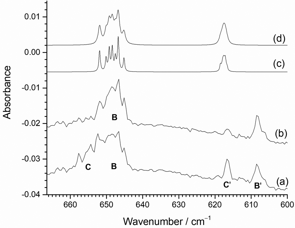
The peaks at 653.7 cm−1 (C), 647.2 cm−1 (B), 616.7 cm−1 (C′) and 608.3 cm−1 (B′) have interesting behaviour under both photolysis and annealing. They are all present on deposition in both 0.2% and 0.5% F2/Ar matrices, and grow on UV photolysis. However, on annealing to 20 K the 653.7 cm−1 (C) and 616.7 cm−1 (C′) features reduce in intensity, whilst those at 647.2 cm−1 (B) and 608.3 cm−1 (B′) increase. Annealing to higher temperatures results in the further reduction of the 653.7 cm−1 (C) and 616.7 cm−1 (C′) features. When annealing was carried out first, similar behaviour was observed (Fig. 9(i)) with a switching of intensity between the C/C′ pairs at 653.7/616.7 cm−1 and the B/B′ pairs at 647.2/608.3 cm−1. After UV photolysis all four peaks increased in intensity, and on subsequent annealing the 653.7 cm−1 (C) and 616.7 cm−1 (C′) features reduced in intensity again, whilst those at 647.2 cm−1 (B) and 608.3 cm−1 (B′) increased. As a result of this observed behaviour, the B peak at 647.2 cm−1 and B′ peak at 608.3 cm−1 are assigned to one species, whilst the C peak at 653.7 cm−1 and the C′ peak at 616.7 cm−1 are assigned to another species. The DFT calculations indicate that MoF2 is bent with two IR active νMo-F bands expected in this region, separated by about 30 cm−1. The lower wavenumber band due to the ν1 symmetric stretching mode is predicted to have lower intensity and to have a more compressed molybdenum isotope pattern (Fig. 3) than the ν3 anti-symmetric stretching mode at higher wavenumber.
As both sets of bands are observed on deposition and after UV photolysis, they most likely belong to very similar species, and it is only on annealing to 20 K that their behaviour changes. Therefore, they are assigned to MoF2 in different matrix sites, and that the higher wavenumber pair of C and C′ at 653.7 cm−1 and 616.7 cm−1 relax to the lower wavenumber pair B and B′ at 647.2 and 608.3 cm−1 on annealing.
Higher resolution spectra of this region are shown in Fig. 11. together with the calculated isotope patterns. Fig. 11(a) shows the spectrum after deposition, photolysis cycle and annealing to 15 K. The two pairs of bands are clearly visible, but after further annealing to 20 K and 25 K (Fig. 11(b)), the higher wavenumber components of the two pairs of bands at 653.7 cm−1 (C) and 616.7 cm−1 (C′) have decreased in intensity, compared to the lower wavenumber bands at 647.2 cm−1 (B) and 608.3 cm−1 (B′). The B3LYP/def2tzvpp calculated isotope patterns in Fig. 11(c) and (d) have been scaled to the 98Mo ν3 peak at 646.7 cm−1. The agreement between this and the single set of isotopic structure in Fig. 11(b) is very good. Although the positions of the experimental and computational ν1 modes at lower wavenumbers do not align completely, the relative intensities match well and the lack of isotopic structure on the ν1 band is similar in both the experimental and calculated data, confirming the assignment to MoF2 in two different sites. The B3LYP/def2tzvpp minimized geometry had a bond angle of 132°, and SVFF calculations using the position of the 92Mo and 100Mo peaks at 651.9 and 645.1 cm−1, respectively, gives a bond angle of 134°, and the calculated position of the 98Mo component is 646.7 cm−1, compared to the experimental value of 646.7 cm−1. (The scaled B3LYP/def2tzvpp calculated values are: 92MoF2, 651.9 cm−1; 98MoF2 646.8 cm−1; 100MoF2, 645.2 cm−1.) For a linear MoF2 unit, SVFF calculations using the 92Mo value of 651.8 cm−1 indicate that the 98Mo and 100Mo peaks would be at 645.9 and 644.1 cm−1, respectively, significantly different to the values observed. Using the 98Mo values of ν3 (646.7 cm−1) and ν1 (608.3 cm−1) and SVFF analysis with a bond angle of 134° yields force constants of fr = 371.6 N m−1 and frr = 19.37 N m−1, compared to 394.2 and 32.89 N m−1 derived from the computational values.
 | ||
| Fig. 11 Higher resolution (1.0 cm−1) infrared spectra of reaction products of atomic Mo in 0.5% F2/Ar matrix with the heated Mo filament protected from F2 using the Cu disc (a) after deposition, broadband photolysis and annealing to 15 K; (b) after subsequent annealing to 20 and then 25 K; calculated (B3LYP/def2tzvpp) and scaled spectra (to ν3) for MoF2 at (c) 0.5 cm−1 and (d) 1 cm−1 fwhm. | ||
Therefore, the Mo isotope patterns on both ν3 and ν1, together with the DFT and SVFF calculations confirm the assignment of these features to MoF2, and that it is a severely bent molecule with a bond angle of ca. 133°. The data for MoF2 are collected together in Table 3.
| Experimental | Computational | ||||||||
|---|---|---|---|---|---|---|---|---|---|
| This work | Label | Ref. 23 | Ref. 19 and 20 | Ref. 21 and 22 | B3LYP/def2tzvpp (this work) | B3LYP/6-31++G9df)-Stuttgart-Dresden92 | CASSCF-XMCQDPT242 | MCQDPT266 | |
| MoF | 573.8 | A | 620.1 | 597 | |||||
| MoF2 | 653.7 | C | 665.5 | ||||||
| 616.7 | C′ | 635.0 | |||||||
| 647.2 | B | ||||||||
| 608.3 | B′ | ||||||||
| MoF3 | 684.6 | E | 633 | 692.3 | 706 | ||||
| MoF4 | 676.0 | D | 733 | 674.0 | 675 | 678.8 | 684 | ||
| MoF5 | 768.9 | F′ | 713 | 761.5 | 774 | ||||
| 694.3 | F | 683 | 693.5 | 694 | 689.5 | 708 | |||
| 658.0 | 658 | 650.0 | 662 | ||||||
| MoF6 | 737.2 | G | 735 | 737.7 | 736 | 734.2 | |||
| 737 | |||||||||
As for MoF, we believe that this is the first spectroscopic identification of MoF2. It should be noted that similar argon matrix site behaviour has also been observed for TiF2103 and PdF2,104 and our recent work on nickel fluorides in solid argon showed that when NiF2 was prepared from nickel atoms and F2 or F atoms, there are two major matrix sites, with the higher energy one reducing on annealing, but thermally evaporated NiF2 displays only one major matrix site.105
Identification of MoF5, MoF4 and MoF3
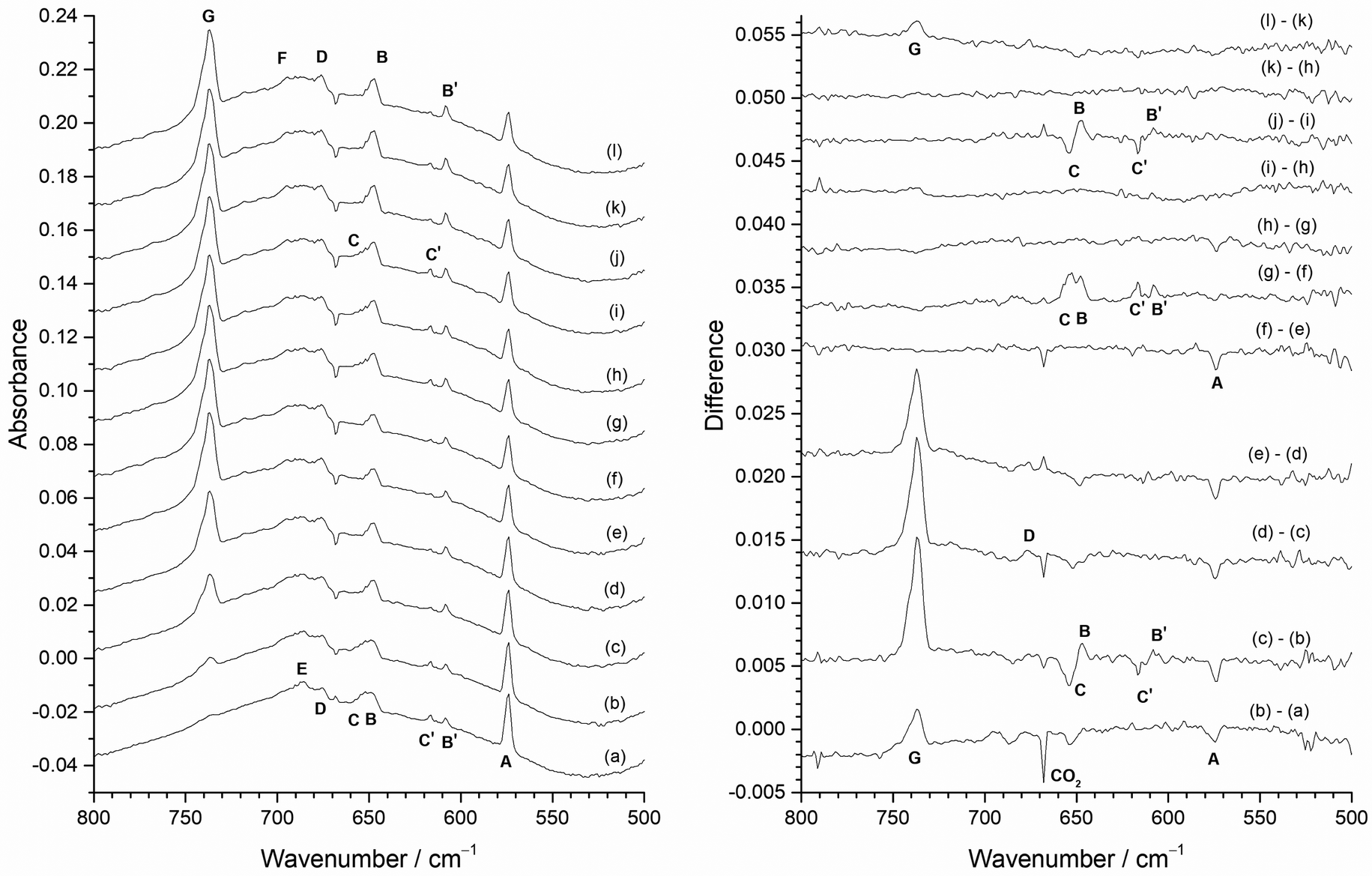
In order to identify the spectral features of the higher fluorides, MoF3, MoF4 and MoF5, photolysis and annealing experiments were carried out with a 1% F2/Ar matrix and the results are shown in Fig. 12. The infrared spectrum after deposition (Fig. 12(a)) contained peaks due to MoF at 573.8 cm−1 (A), and those from MoF2 at 608.3 cm−1 (B′) and 616.7 cm−1 (C′) as well as the broad feature at 650 cm−1, and the MoF6 band at 737.2 cm−1 (G), which were also observed in the 0.5% F2/Ar spectrum (Fig. 8 and 9). In addition, there is a set of overlapping peaks (D, E, F) between 670 and 705 cm−1, which were not observed in the 0.2% F2/Ar experiments, but were observed in 0.5%, 1% and 2% F2/Ar experiments (Fig. 7). There is also a weak peak (F′) at 768.9 cm−1.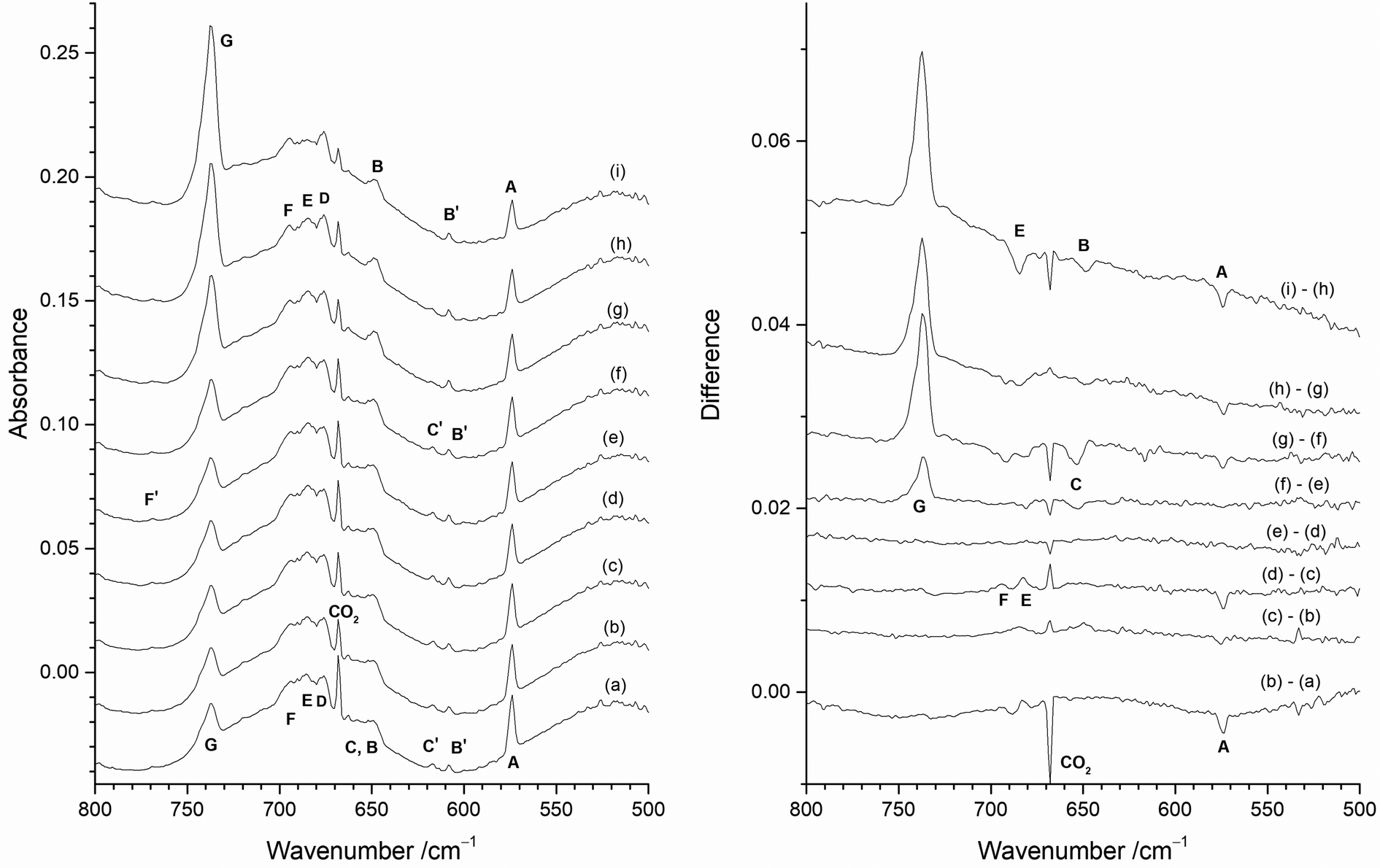 | ||
| Fig. 12 Infrared absorbance (left) and difference (right) spectra of reaction products of Mo atoms in 1% F2/Ar matrix with the heated Mo filament protected from F2 using the Cu disc: (a) after deposition; (b) after 10 min visible light photolysis (400–700 nm); (c) after 10 min UV photolysis (240–410 nm); (d) after 10 min broadband photolysis (240–800 nm); (e) after further 10 min visible light photolysis (400–700 nm); (f) after 5 min annealing at 15 K; (g) after 5 min annealing at 20 K; (h) after 5 min annealing at 25 K; (i) after 5 min annealing at 30 K. | ||
After visible photolysis (400–700 nm) (Fig. 12(b)) the intensity of the peak at 573.8 cm−1 (A) reduced slightly, with little change in the intensity of the other bands. After UV photolysis (240–410 nm) (Fig. 12(c)) no significant change was observed in the intensity of the features, but after broadband photolysis (240–800 nm) (Fig. 12(d)), the peak at 573.8 cm−1 (A) decreased again, and there was a slight increase in bands at 684.6 cm−1 (E) and 694.3 cm−1 (F). No further change was observed after further visible light photolysis (Fig. 12(e)). Annealing experiments were undertaken after photolysis, and after annealing to 15 K (Fig. 12(f)), there was an increase in the MoF6 peak at 737.2 cm−1 (G) and apart from this there was very little change except for a slight reduction in intensity of the band at 653.7 cm−1 (C). After annealing at 20 K, (Fig. 12(g)) the MoF6 band at 737.2 cm−1 (G) significantly increased in intensity and the MoF feature at 573.8 cm−1 (A) and those due to MoF2 at 653.7 cm−1 (C) and 616.7 cm−1 (C′) decreased in intensity, with a slight increase in the second set of MoF2 peaks at 647.2 cm−1 (B) and 608.3 cm−1 (B′). The difference spectrum indicates a very a slight change in relative intensity and band shapes of 676.0 cm−1 (D), 684.6 cm−1 (E) and 694.3 cm−1 (F) bands. After annealing at 25 K (Fig. 12(h) the MoF6 band at 737.2 cm−1 (G) significantly increased in intensity again, and the intensity of the MoF peak at 573.8 cm−1 (A) reduced slightly in intensity. After further annealing at 30 K (Fig. 12(i)) the absorptions at 573.8 cm−1 (A), and 647.2 cm−1 (B) decreased. In the 670–700 cm−1 region, the central component at 684.6 cm−1 (E) reduced in intensity with respect to the other two bands at 694.3 cm−1 (F) and 676.0 cm−1 (D), and the MoF6 band at 737.2 cm−1 (G) increased significantly in intensity. There was no observable change in the intensity of the weak peak at 768.9 cm−1 (F′) under any of the photolysis and annealing conditions.
Therefore, the behaviour of the MoF and MoF2 peaks between 660 and 550 cm−1 on photolysis and annealing in the 1% F2/Ar spectra was consistent with that observed in the 0.5% F2/Ar and 0.2% F2/Ar matrices. The G peak due to MoF6 at 737.2 cm−1 was unaffected by photolysis but increased on annealing at 15, 20, 25 and 30 K. Although broadband photolysis of MoF6 in argon matrices has previously resulted in the formation of MoF5 at 693.5 and 658.0 cm−1,19,20 this was not observed in these experiments, presumably because of the presence of F2 and F atoms in the matrix allow for ready recombination. The cluster of peaks between 710 and 670 cm−1 with peak positions at 676.0 cm−1 (D), 684.6 cm−1 (E) and 694.3 cm−1 (F) were more intense in the 1% F2/Ar data than the 0.5% or 0.2% F2/Ar matrices. These had similar behaviour (with some evidence of slightly changing band shapes) after all photolysis and annealing conditions apart from annealing to 30 K (Fig. 12(i)), where the central feature at 684.6 cm−1 (E) reduced in intensity compared to the outer features at 676.0 cm−1 (D) and 694.3 cm−1 (F). There is a weak peak at 768.9 cm−1 (F′) present in all these spectra, which was unaffected by either photolysis or annealing, which correlates with the 694.3 cm−1 (F) peak.
When a 2% F2/Ar gas mixture was used, the results were very similar to that obtained for 1% F2/Ar and these are shown in Fig. 7 as well as the ESI† (Fig. ESI-5 and ESI-6, ESI†). The most significant difference between the spectra of the 1% F2/Ar and 2% F2/Ar mixtures on deposition is shown in Fig. 7 where the central component of the three-peak cluster at 684.6 cm−1 (E) has a much lower intensity in the 2% F2/Ar experiment (Fig. 7(d)) compared to 1% F2/Ar one (Fig. 7(c)), to the extent that it has almost disappeared. There was very little change after photolysis, apart from the reduction in the MoF peak at 573.8 cm−1 (A) on visible and broadband photolysis. The peak due to MoF6 at 737.2 cm−1 (G) grew significantly after annealing to 15, 20, 25 and 30 K. There were also some minor changes in the relative intensities of the cluster of peaks between 710 and 660 cm−1.
In the previous work involving the photolysis of MoF6 in solid argon, a peak at 693.5 cm−1 was assigned to MoF5, together with a weaker feature at 658.0 cm−1, with about 30–40% of the intensity of the 693.5 cm−1 peak.19,20 In the work involving the reaction of fluorine with heated molybdenum, bands at 694 and 658 cm−1 were also assigned to MoF5.21,22 The behaviour of the peak in our spectra at 694.3 cm−1 (F) is consistent with its assignment to MoF5. There is no clear evidence for the 658.0 cm−1 peak in our spectra, but this could be masked by the complex set of MoF2 peaks in this region. The DFT calculations for MoF5 (Table 1) predict three IR active modes at 761.5, 689.5 and 650.0 cm−1 and there is a weak peak at 768.9 cm−1 (F′) in the experimental spectra whose intensity correlates with the 694.3 cm−1 (F) peak, and we assign this to MoF5 as well. The recent MCQDPT2 calculations also predicted three νMo–F modes with considerable IR intensity at 774, 708, and 662 cm−1, and they assigned the lower two to those observed at 694 and 658 cm−1 in the previous reports,19–22 but offered no explanation for the missing peak at higher wavenumber. The data reported here have identified the two higher energy νMo–F modes, with the lower energy one probably being masked by other features.
Peaks at ca. 675 cm−1 have been previously assigned to MoF4,19–22 and the behaviour of the peak at 676.0 cm−1 (D) in our spectra is also consistent with this assignment.
The previous tentative assignment of a band at 633 cm−1 to MoF321,22 has been called into question by Sliznev and Belova42 who predicted that the experimental value for MoF3 would be close to 696 cm−1, based on the calculated value for ω3(E′) of 706 cm−1. They commented that in the experimental work involving the reaction of F2 and heated Mo21,22 there was a band at 694 cm−1, which could be reassigned to MoF3, but on the basis of the above discussion this is best assigned to MoF5. Our calculations also indicate that MoF3 should have an IR active νMo–F mode at 692 cm−1, slightly higher than that of MoF4. The only significant band not assigned in the spectra is the central 684.6 cm−1 (E) component of the multi-peak cluster at 690–667 cm−1. This peak has the greatest relative intensity in the 0.5% F2/Ar spectrum on deposition and reduces on annealing. In the 1% F2/Ar spectrum there is similar behaviour where it reduces on annealing. In the 2% F2/Ar spectra it is much weaker than the bands assigned to MoF5 at 694.3 cm−1 (F) and MoF4 at 676.0 cm−1 (D), and this is also shown more clearly in Fig. ESI-7 (ESI†). Therefore, a combination of the experimental and calculated data indicates that the 684.6 cm−1 (E) peak is best assigned as the E′ stretching mode of MoF3.
Higher resolution spectra for both the 1% F2/Ar and 2% F2/Ar experiments are shown in Fig. ESI-7 (ESI†), and these confirm that all the 694.3 cm−1 (F), 684.6 cm−1 (E) and 676.0 cm−1 (D) bands display molybdenum isotopic structure. However, because the three bands are overlapping it is difficult to fully resolve, but the increased spread of the features in MoF3 compared to MoF4 helps to confirm the assignments.
Therefore, all MoFn molecules have had their IR active νMo–F modes identified for the first time and the data are collected together in Table 3.
Identification of (MoF5)3
Having assigned the peaks in the spectra with the copper disc protecting the hot Mo filament from reacting with the F2/Ar mixture, it is now possible to return to Fig. 6(a) and identify the remaining features. Fig. ESI-8 (ESI†) shows that there is no effect on the features in these experiments after either photolysis or annealing. The most intense peak at 737.8 cm−1 can readily be assigned to MoF6 from both the previous work and that reported herein. Likewise, the peak at 675.0 cm−1 can be assigned to MoF4. Shifts of the product peaks between different experimental conditions have been observed previously.21,22 The remaining features at 767.6, 719.7, 707.5 and 696.0 cm−1 (labelled as T) are in reasonable agreement with those of 768, 716 and 704 cm−1 assigned to polymeric species by Acquista and Abramowitz who studied the (cracked) vapour above heated MoF5,23 and also to those at 768, 715, 705 and possibly 692 cm−1 in an approximate intensity ratio of 1:2:1:0.5, reported by Osin et al. for (MoF5)3, in their work on the reaction of fluorine with heated molybdenum.21,22 (There was some variation in peak position and relative intensities between their spectra recorded at different molybdenum filament temperatures and fluorine flow rates). They also assigned a Mo–F–Mo bridging stretching mode to a feature at 522 cm−1, which was broad and had about half the intensity of their 768 cm−1 peak.21,22 In our spectra (Fig. ESI-8, ESI†) there is a weak, but consistent feature at 526.0 cm−1 which could be tentatively assigned to this bridging mode. A summary of the data observed in the experiments carried out without the copper disc is given in Table 4.
Conclusions
In this study all of the molecular monomeric molybdenum fluorides have been identified, providing the first spectroscopic evidence for MoF2 and MoF, a reassignment for MoF3, and clarification for MoF5 and (MoF5)3.MoF at 573.8 cm−1 (A) is only observed when the copper disc is used to protect the heated molybdenum filament from reaction with the fluorine, implying that it is a product of the reaction of molybdenum atoms and fluorine. It is formed on deposition at all fluorine concentrations studied (0.2%, 0.5%, 1%, 2%), and is the major feature observed on deposition with 0.2% F2/Ar matrices. As the fluorine concentration increases, it is still present, but the features due to other MoFn species become more relatively intense. On visible and broadband photolysis its intensity is reduced slightly, as it is on annealing. Its presence is confirmed by the molybdenum isotope pattern, and we believe that this is its first spectroscopic characterisation, although we suspect that this is the feature labelled as F, but unassigned, in the laser ablation studies using Mo and either OF2 or F2 doped argon matrices.52 The presence of MoF indicates that there are likely to be fluorine atoms present in the matrix on deposition, and certainly after UV photolysis.106 The formation of monofluorides from thermally evaporated metal atoms and molecular fluorine has also been observed in the case of titanium,103 palladium,104 and nickel.105 Although the calculations indicate that ArMoF may be present, in the absence of convincing experimental data, we have assigned the 573.8 cm−1 band to MoF.
MoF2 is also only present when the copper disc is used to protect the hot filament, indicating that it too is a reaction product of molybdenum atoms and fluorine. On deposition it is found in two sites (653.7 cm−1 (C) and 616.7 cm−1 (C′) and 647.2 cm−1 (B) and 608.3 cm−1 (B′)) in approximately equal quantities in the experiments involving 0.5% F2/Ar and 1% F2/Ar matrices, but these bands are hardly present in the 0.2% F2/Ar or 2% F2/Ar matrices. Their intensity increases after UV photolysis, indicating a reaction between molybdenum atoms and fluorine atoms, rather than fluorine molecules. On annealing to 20, 25 and 30 K, the higher wavenumber site (653.7/616.7 cm−1) is converted to the lower wavenumber site (647.2/608.3 cm−1). When annealing is carried out before photolysis the same behaviour is observed, and on subsequent UV irradiation the higher wavenumber site can be repopulated, but it is depleted again on subsequent annealing. The assignment is confirmed by the different isotope patterns observed for ν3 and ν1. As for MoF, we believe that this is the first spectroscopic characterization of MoF2, and the experimental and computational data confirm that it is a bent molecule with a bond angle of ca. 133°. Similar site effects have also been observed for MF2 species such as TiF2,103 PdF2104 and NiF2.105
MoF3 is present at 684.6 cm−1 (E) in the 0.5% and 1% F2/Ar experiments with the protective copper disc, but is absent in the 0.2% F2/Ar matrices, and is weaker in the 2% F2/Ar experiments, indicating that it also results from the reaction of molybdenum atoms and fluorine. There is no change on photolysis and little change on annealing, apart from a slight reduction in intensity after annealing to 20, 25 and 30 K. Although not fully resolved the molybdenum isotopic structure is consistent with this assignment.
MoF4 at 676.0 cm−1 (D) is observed in spectra both with and without the protective copper disc present, indicating that it can be formed both from a reaction of fluorine with molybdenum atoms as well as a hot molybdenum surface. In the experiments with the copper disc, its relative intensity grows from 0.5% to 1% F2/Ar to 2% F2/Ar. In the experiments both with and without the copper disc there is little or no change on photolysis or annealing.
For MoF5, the B3LYP/def2tzvpp calculations predict three IR bands at 761.5, 689.5 and 650.0 cm−1 for the Jahn-Teller distorted MoF5, but only two of these at 768.9 cm−1 (F′) and 694.3 cm−1 (F) have been identified with certainty in this work using the copper disc. The lower wavenumber component observed by other workers at 658 cm−1 is probably masked by the MoF2 features. The 768.9 cm−1 (F′) and 694.3 cm−1 (F) bands are hard to detect in the 0.5% F2/Ar experiment, the main peak at 694.3 cm−1 (F) is a shoulder in the 1% F2/Ar experiments and a clear peak in the 2% F2/Ar experiments. As for MoF4 there is very little photochemical or annealing behaviour. Although not possible to state with complete certainty, it is more reasonable to conclude that the MoF3 monomer is only formed from the reaction of molybdenum atoms and fluorine rather than a hot molybdenum surface.
MoF6 is observed in the experiments with and without the copper disc. For the experiments with the copper disc, the peak at 737.2 cm−1 (G) is not present in the 0.2% F2/Ar experiments on deposition, is very weak in the 0.5% F2/Ar matrices, increases in intensity in the 1% F2/Ar spectra and is the most intense in the 2% F2/Ar matrices. It does not grow on photolysis, but the intensity does increase on annealing from 15 K onwards. In the experiments where the annealing was carried out first, there was also a marked increase in the intensity of this feature, indicating that it is most likely formed from the reaction of molybdenum atoms and fluorine molecules, rather than fluorine atoms. In the experiments without the copper disc, MoF6 is shifted very slightly and is observed at 737.8 cm−1.
The bands at 767.6, 719.7, 707.5 and 696.0 cm−1 (T) as well as the bridging mode at 526.0 cm−1 can be assigned to (MoF5)3, in good agreement with previous work. These features are only observed in the absence of the copper disc, indicating that (MoF5)3 is formed from a reaction of the fluorine molecules with the surface of the heated molybdenum filament, and the reaction products are then vaporised and trapped in the solid argon matrix.
Therefore, all the molybdenum fluorides MoFn, where n = 1 to 6 have been prepared using the reaction between fluorine and thermally evaporated molybdenum atoms, and MoF4, (MoF5)3 and MoF6 have also been formed from the reaction of fluorine and the surface of the heated molybdenum filament, and then sublimed from the surface.
Conflicts of interest
There are no conflicts to declare.Acknowledgements
The University of Hull is thanked for the award of a PhD studentship to AKS and for supporting the work financially. The EPSRC are thanked for financially supporting this work through access to the Chemical Database Service at Daresbury Laboratory107 and also the Royal Society of Chemistry. Prof. Ian Beattie is thanked for the gift of the molybdenum wire. Prof. Adam Bridgeman is thanked for many helpful discussions.Notes and references
- G. A. West and K. W. Beeson, J. Electrochem. Soc., 1988, 135, 1752–1757 CrossRef CAS
.
- N. Lifshitz and M. L. Green, J. Electrochem. Soc., 1988, 135, 1832–1836 CrossRef CAS
- M. H. J. M. de Croon, E. N. Orij and G. B. Marin, Chem. Eng. Sci., 1999, 54, 3315–3325 CrossRef CAS
- G. Di Giuseppe and J. R. Selman, J. Electroanal. Chem., 2003, 559, 31–43 CrossRef CAS
- A. U. Mane, S. Letourneau, D. J. Mandia, J. Liu, J. A. Libera, Y. Lei, Q. Peng, E. Graugnard and J. W. Elam, J. Vac. Sci. Technol., A, 2018, 36, 01A125 CrossRef
- O. Ruff and F. Eisner, Ber. Dtsch. Chem. Ges., 1907, 40, 2926–2935 CrossRef CAS
- T. G. Burke, D. F. Smith and A. H. Nielsen, J. Chem. Phys., 1952, 20, 447–454 CrossRef CAS
- J. Gaunt, Trans. Faraday Soc., 1953, 49, 1122–1131 RSC
- H. H. Claassen, H. Selig and J. G. Malm, J. Chem. Phys., 1962, 36, 2888–2890 CrossRef CAS
- H. H. Claassen, G. L. Goodman, J. H. Holloway and H. Selig, J. Chem. Phys., 1970, 53, 341–348 CrossRef CAS
- Y. M. Bosworth, R. J. H. Clark and D. M. Rippon, J. Mol. Spectrosc., 1973, 46, 240–255 CrossRef CAS
- R. S. McDowell, R. J. Sherman, L. B. Asprey and R. C. Kennedy, J. Chem. Phys., 1975, 62, 3974–3978 CrossRef CAS
- R. S. McDowell, Spectrochim. Acta, Part A, 1986, 42A, 1053–1057 CrossRef CAS
- J. C. Cummings, J. Mol. Spectrosc., 1980, 83, 417–430 CrossRef CAS
- S. S. Nabiev and V. D. Klimov, Mol. Phys., 1994, 81, 395–408 CrossRef CAS
- R. Holland, W. B. Maier, II, S. M. Freund and W. H. Beattie, J. Chem. Phys., 1983, 78, 6405–6414 CrossRef CAS
- R. D. Hunt, L. Andrews and L. M. Toth, Inorg. Chem., 1991, 30, 3829–3832 CrossRef CAS
- R. D. Hunt, L. Andrews and L. M. Toth, J. Phys. Chem., 1991, 95, 1183–1188 CrossRef CAS
- O. V. Blinova and Y. B. Predtechenskii, Opt. Spectrosc., 1979, 47, 622–624 Search PubMed
- O. V. Blinova and Y. B. Predtechenskii, Opt. Spektrosk., 1979, 47, 1120–1125 CAS
- S. B. Osin, D. I. Davlyatshin and J. S. Ogden, Zh. Fiz. Khim., 2001, 75, 294–302 CAS
- S. B. Osin, D. I. Davlyatshin and J. S. Ogden, Russ, J. Phys. Chem., 2001, 75, 237–245 Search PubMed
- N. Acquista and S. Abramowitz, J. Chem. Phys., 1973, 58, 5484–5488 CrossRef CAS
- S. Siegel and D. A. Northrop, Inorg. Chem., 1966, 5, 2187–2188 CrossRef CAS
- J. H. Levy, J. C. Taylor and P. W. Wilson, Acta Crystallogr., Sect. B: Struct. Crystallogr. Cryst. Chem., 1975, B31, 398–401 CrossRef CAS
- T. Drews, J. Supel, A. Hagenbach and K. Seppelt, Inorg. Chem., 2006, 45, 3782–3788 CrossRef CAS PubMed
- A. K. Brisdon, J. H. Holloway, E. G. Hope, W. Levason, J. S. Ogden and A. K. Saad, J. Chem. Soc., Dalton Trans., 1992, 447–449 RSC
- H. M. Seip and R. Seip, Acta Chem. Scand., 1966, 20, 2698–2710 CrossRef CAS
- L. S. Bartell, J. W. Hovick, T. S. Dibble and P. J. Lennon, J. Phys. Chem., 1993, 97, 230–232 CrossRef CAS
- K. Seppelt, Chem. Rev., 2015, 115, 1296–1306 CrossRef CAS PubMed
- G. S. Quiñones, G. Hägele and K. Seppelt, Chem. – Eur. J., 2004, 10, 4755–4762 CrossRef PubMed
- R. E. Stene, B. Scheibe, C. Pietzonka, A. J. Karttunen, W. Petry and F. Kraus, J. Fluor. Chem., 2018, 211, 171–179 CrossRef CAS
- I. S. Gotkis and A. V. Gusarov, Chem. Abs., 1983, 98, 41019 Search PubMed
- M. J. Vasile, G. R. Jones and W. E. Falconer, Int. J. Mass Spectrom. Ion Phys., 1973, 10, 457–469 CrossRef CAS
- I. S. Gotkis, A. V. Gusarov, V. S. Pervov and V. D. Butskii, Koord. Khim., 1978, 4, 720–724 CAS
- G. V. Girichev, N. I. Giricheva and O. G. Krasnova, J. Mol. Struct., 2001, 567-568, 203–210 CrossRef CAS
- M. J. Vasile, G. R. Jones and W. E. Falconer, Adv. Mass Spectrom., 1974, 6, 557–563 CAS
- I. P. Malkerova, A. S. Alikhanyan, V. D. Butskii, V. S. Pervov and V. I. Gorgoraki, Zh. Neorg. Khim., 1985, 30, 2761–2765 CAS
- O. G. Krasnova, N. I. Giricheva, G. V. Girichev, A. V. Krasnov, V. M. Petrov and V. D. Butskii, Izv. Vyssh. Uchebn. Zaved., Khim. Khim. Tekhnol., 1995, 38, 28–33 CAS
- A. S. Alikhanyan, A. V. Steblevskii, I. P. Malkerova, V. S. Pervov, V. D. Butskii and V. I. Gorgoraki, Zh. Neorg. Khim., 1978, 23, 1477–1482 CAS
- D. L. Hildenbrand, J. Chem. Phys., 1976, 65, 614–618 CrossRef CAS
- V. V. Sliznev and N. V. Belova, J. Mol. Struct., 2017, 1132, 73–87 CrossRef CAS
- L. H. Jones and S. Ekberg, J. Chem. Phys., 1977, 67, 2591–2595 CrossRef CAS
- W. Levason, R. Narayanaswamy, J. S. Ogden, A. J. Rest and J. W. Turff, J. Chem. Soc., Dalton Trans., 1981, 2501–2507 RSC
- S. B. Osin, D. I. Davliatshin and J. S. Ogden, J. Fluorine Chem., 1996, 76, 187–192 CrossRef CAS
-
D. M. Gruen, in Cryochemistry, ed. M. Moskovits and G. A. Ozin, Wiley-Interscience, New York, 1976, pp. 441–491 Search PubMed
-
A. N. Nesmeyanov, Vapor Pressure of the Chemical Elements, Elsevier, 1963 Search PubMed
- Y. Gong and L. Andrews, Inorg. Chem., 2012, 51, 667–673 CrossRef CAS PubMed
- X. Wang, L. Andrews, F. Brosi and S. Riedel, Chem. – Eur. J., 2013, 19, 1397–1409 CrossRef CAS PubMed
- A. Cezairliyan, Int. J. Thermophys., 1980, 1, 417–427 CrossRef CAS
-
J. H. Weaver, C. Krafka, D. W. Lynch and E. E. Koch, Optical Properties of Metals. Part I: The Transition Metals, Fachinformationszentrum Energie, Physik, Mathematik, Karlsruhe, 1981 Search PubMed
- R. Wei, Q. Li, Y. Gong, L. Andrews, Z. Fang, K. S. Thanthiriwatte, M. Vasiliu and D. A. Dixon, J. Phys. Chem. A, 2017, 121, 7603–7612 CrossRef CAS PubMed
-
M. J. Frisch, G. W. Trucks, H. B. Schlegel, G. E. Scuseria, M. A. Robb, J. R. Cheeseman, G. Scalmani, V. Barone, B. Mennucci, G. A. Petersson, H. Nakatsuji, M. Caricato, X. Li, H. P. Hratchian, A. F. Izmaylov, J. Bloino, G. Zheng, J. L. Sonnenberg, M. Hada, M. Ehara, K. Toyota, R. Fukuda, J. Hasegawa, M. Ishida, T. Nakajima, Y. Honda, O. Kitao, H. Nakai, T. Vreven, J. J. A. Montgomery, J. E. Peralta, F. Ogliaro, M. Bearpark, J. J. Heyd, E. Brothers, K. N. Kudin, V. N. Staroverov, T. Keith, R. Kobayashi, J. Normand, K. Raghavachari, A. Rendell, J. C. Burant, S. S. Iyengar, J. Tomasi, M. Cossi, N. Rega, J. M. Millam, M. Klene, J. E. Knox, J. B. Cross, V. Bakken, C. Adamo, J. Jaramillo, R. Gomperts, R. E. Stratmann, O. Yazyev, A. J. Austin, R. Cammi, C. Pomelli, J. W. Ochterski, R. L. Martin, K. Morokuma, V. G. Zakrzewski, G. A. Voth, P. Salvador, J. J. Dannenberg, S. Dapprich, A. D. Daniels, O. Farkas, J. B. Foresman, J. V. Ortiz, J. Cioslowski and D. J. Fox, Gaussian 09 (Revision D.01), Gaussian Inc., Wallingford, CT, 2013 Search PubMed
- T. A. Manz and N. G. Limas, RSC Adv., 2016, 6, 47771–47801 RSC
- N. G. Limas and T. A. Manz, RSC Adv., 2016, 6, 45727–45747 RSC
- T. A. Manz, RSC Adv., 2017, 7, 45552–45581 RSC
- I. R. Beattie, N. Cheetham, M. Gardner and D. E. Rogers, J. Chem. Soc. A, 1971, 2240–2245 RSC
-
K. Nakamoto, Infrared and Raman Spectra of Inorganic and Coordination Compounds: Part A: Theory and Applications in Inorganic Chemistry, John Wiley & Sons, Inc., 6th edn, 2008 Search PubMed
- R. Craciun, R. T. Long, D. A. Dixon and K. O. Christe, J. Phys. Chem. A, 2010, 114, 7571–7582 CrossRef CAS PubMed
- V. V. Sliznev and V. G. Solomonik, Zh. Neorg. Khim., 2000, 45, 1172–1174 CAS
- V. V. Sliznev and V. G. Solomonik, Russ. J. Inorg. Chem., 2000, 45, 1060–1062 Search PubMed
- B. Roessler and K. Seppelt, Angew. Chem., Int. Ed., 2000, 39, 1259–1261 CrossRef CAS PubMed
- M. J. Molski and K. Seppelt, Dalton Trans., 2009, 3379–3383 RSC
- A. R. Rossi and R. Hoffmann, Inorg. Chem., 1975, 14, 365–374 CrossRef CAS
- E. I. Voit, A. V. Voit, V. K. Goncharuk and V. I. Sergienko, J. Struct. Chem., 1999, 40, 380–386 CrossRef CAS
- V. V. Sliznev, O. A. Pimenov and G. V. Girichev, J. Mol. Struct., 2020, 1199, 126884 CrossRef CAS
- N. I. Giricheva and G. V. Girichev, Izv. Vyssh. Uchebn. Zaved., Khim. Khim. Tekhnol., 1991, 34, 3–11 CAS
- O. G. Grasnova, G. V. Girichev, N. I. Giricheva, A. V. Krasnov and V. D. Butskii, Izv. Vyssh. Uchebn. Zaved., Khim.
Khim. Tekhnol., 1994, 37, 50–56 CAS
- N. I. Giricheva, O. G. Krasnova and G. V. Girichev, J. Struct. Chem., 1997, 38, 54–61 CrossRef CAS
- G. V. Girichev, V. N. Petrova, V. M. Petrov, K. S. Krasnov and V. K. Goncharuk, J. Struct. Chem., 1983, 24, 375–378 CrossRef
- G. V. Girichev, V. N. Petrova, V. M. Petrov, K. S. Krasnov and V. K. Goncharuk, Izv. Vyssh. Uchebn. Zaved., Khim. Khim. Tekhnol., 1981, 24, 131–132 CAS
- A. J. Edwards, R. D. Peacock and R. W. H. Small, J. Chem. Soc., 1962, 4486–4491 RSC
- V. V. Sliznev and V. G. Solomonik, J. Struct. Chem., 2000, 41, 11–18 CrossRef CAS
- V. V. Sliznev and V. G. Solomonik, Zh. Neorg. Khim., 2000, 45, 513–522 CAS
- V. V. Sliznev and V. G. Solomonik, Russ. J. Inorg. Chem., 2000, 45, 447–456 Search PubMed
- V. Gutmann and K. H. Jack, Acta Crystallogr., 1951, 4, 244–246 CrossRef CAS
- F. Averdunk and R. Hoppe, J. Less-Common Met., 1990, 161, 135–140 CrossRef CAS
- S. G. Wang and W. H. E. Schwarz, J. Chem. Phys., 1998, 109, 7252–7262 CrossRef CAS
- O. M. Wilkin, N. Harris, J. F. Rooms, E. L. Dixon, A. J. Bridgeman and N. A. Young, J. Phys. Chem. A, 2018, 122, 1994–2029 CrossRef CAS PubMed
- P. E. M. Siegbahn, Theor. Chim. Acta, 1994, 87, 441–452 CrossRef CAS
- V. R. Jensen, Mol. Phys., 1997, 91, 131–137 CrossRef CAS
- I. M. B. Nielsen and M. D. Allendorf, J. Phys. Chem. A, 2005, 109, 928–933 CrossRef CAS PubMed
- B. Vest, P. Schwerdtfeger, M. Kolonits and M. Hargittai, Chem. Phys. Lett., 2009, 468, 143–147 CrossRef CAS
- B. Vest, Z. Varga, M. Hargittai, A. Hermann and P. Schwerdtfeger, Chem. – Eur. J., 2008, 14, 5130–5143 CrossRef CAS PubMed
- T. Schlöder, F. Brosi, B. J. Freyh, T. Vent-Schmidt and S. Riedel, Inorg. Chem., 2014, 53, 5820–5829 CrossRef PubMed
- J. W. Hastie, R. H. Hauge and J. L. Margrave, J. Chem. Soc. D: Chem. Comm., 1969, 1452–1453 RSC
- V. N. Bukhmarina, A. Y. Gerasimov, Y. B. Predtechenskii and V. G. Shklyarik, Opt. Spektrosk., 1988, 65, 876–881 CAS
- V. N. Bukhmarina, A. Y. Gerasimov, Y. B. Predtechenskii and V. G. Shklyarik, Opt. Spectrosc., 1988, 65, 518–521 Search PubMed
- J. W. Hastie, R. H. Hauge and J. L. Margrave, High Temp. Sci., 1971, 3, 257–274 CAS
- J. S. Ogden and R. S. Wyatt, J. Chem. Soc., Dalton Trans., 1987, 859–865 RSC
- P. E. M. Siegbahn, Theor. Chim. Acta, 1993, 86, 219–228 CrossRef CAS
- L. Cheng, M. Y. Wang, Z. J. Wu and Z. M. Su, J. Comput. Chem., 2007, 28, 2190–2202 CrossRef CAS PubMed
- H. H. Claassen, J. Chem. Phys., 1959, 30, 968–972 CrossRef CAS
- C. W. F. T. Pistorius, J. Chem. Phys., 1958, 29, 1328–1332 CrossRef CAS
- F. Ucun and M. G. Şengül, Z. Naturforsch., A: Phys. Sci., 2005, 60, 819–822 CrossRef CAS
- R. M. Badger, J. Chem. Phys., 1935, 3, 710–714 CrossRef CAS
- M. W. Chase, J. Phys. Chem. Ref. Data, 1998, Monograph 9, 1–1951 Search PubMed
- L. E. Forslund and N. Kaltsoyannis, New J. Chem., 2003, 27, 1108–1114 RSC
- D. L. Hildenbrand, J. Chem. Phys., 1975, 62, 3074–3079 CrossRef CAS
- M. Kaupp, D. Danovich and S. Shaik, Coord. Chem. Rev., 2017, 344, 355–362 CrossRef CAS
- B. I. Swanson and L. H. Jones, J. Chem. Phys., 1980, 73, 986–987 CrossRef CAS
- L. H. Jones and B. I. Swanson, J. Chem. Phys., 1983, 79, 1516–1522 CrossRef CAS
- A. V. Wilson, A. J. Roberts and N. A. Young, Angew. Chem., Int. Ed., 2008, 47, 1774–1776 CrossRef CAS PubMed
- A. V. Wilson, T. Nguyen, F. Brosi, X. Wang, L. Andrews, S. Riedel, A. J. Bridgeman and N. A. Young, Inorg. Chem., 2016, 55, 1108–1123 CrossRef CAS PubMed
- L. Li, A. K. Sakr, T. Schlöder, S. Klein, H. Beckers, M.-P. Kitsaras, H. V. Snelling, N. A. Young, D. Andrae and S. Riedel, Angew. Chem., Int. Ed., 2021, 60, 6391–6394 CrossRef CAS PubMed
- E. Y. Misochko, A. V. Akimov and C. A. Wight, Chem. Phys. Lett., 1997, 274, 23–28 CrossRef CAS
- D. A. Fletcher, R. F. McMeeking and D. Parkin, J. Chem. Inf. Comput. Sci., 1996, 36, 746–749 CrossRef CAS
Footnote |
| † Electronic supplementary information (ESI) available. See DOI: https://doi.org/10.1039/d1nj06062g |
| This journal is © The Royal Society of Chemistry and the Centre National de la Recherche Scientifique 2022 |