S-Scheme heterojunction based on the in situ coated core–shell NiCo2S4@WS2 photocatalyst was constructed for efficient photocatalytic hydrogen evolution
Shengming
Xu
a,
Jing
Xu
 *abc,
Linying
Hu
a,
Ye
Liu
a and
Lijun
Ma
a
aSchool of Chemistry and Chemical Engineering, North Minzu University, Yinchuan 750021, P. R. China. E-mail: wgyxj2000@163.com
bNingxia Key Laboratory of Solar Chemical Conversion Technology, North Minzu University, Yinchuan 750021, P. R. China
cKey Laboratory for Chemical Engineering and Technology, State Ethnic Affairs Commission, North Minzu University, Yinchuan 750021, P. R. China
First published on 17th November 2021
Abstract
In this paper, NiCo2S4 was coated on the surface of WS2 of a 1T/2H mixed phase by a two-step hydrothermal method to form an in situ core–shell structure. The unique S-scheme heterojunction of the NiCo2S4@WS2 core–shell composite photocatalyst improved the easy recombination of carriers caused by the narrow band gap of NiCo2S4 and WS2, and improved the photocatalytic hydrogen production performance. The loading ratio of NiCo2S4@WS2, the addition of Eosin Y, and the pH value of TEOA were optimized. Under the optimal conditions, the hydrogen production rate reached 5.814 mmol g−1 h−1, which is about 8.55 times and 3.35 times the hydrogen evolution rates of NiCo2S4 and WS2, respectively. The composite catalyst exhibits excellent charge separation efficiency in photoelectrochemistry, PL and BET tests, carrier transport rate and large specific surface area that can provide more active sites, which are the main factors for the improvement of the hydrogen evolution performance. This paper demonstrates new design strategies to drive efficient photocatalytic hydrogen production by building in situ core–shell structures and optimizing the carrier transport paths, which will yield new insights.
1 Introduction
As a kind of clean energy with high combustion value and H2O combustion product, hydrogen can become an excellent substitute for the increasingly exhausted fossil fuel. Photocatalytic cracking of water, as a green method for producing hydrogen, has been attracting continuous attention since Fujishima and Honda discovered in 1972 that water can produce hydrogen on a semiconductor electrode.1 Some excellent photocatalytic semiconductor materials, such as TiO2,2 CdS,3 ZnO,4 and MoS2,5 have been treated by doping, modification and other methods to possess excellent photocatalytic performance. Transition metal sulfides, such as NiCo2S4, ZnIn2S4, WS2, CdS and MoS2, have been widely studied as electrode materials in the field of photoelectric chemistry due to their excellent photochemical properties.6,7 Among them, the semiconductor NiCo2S4 with low cost and narrow band gap has been partially studied in the field of photocatalysis.8–10 However, as a binary metal sulfide with excellent conductivity and many active sites of redox, it still has a very broad research prospect.11–13 WS2 is also widely used in photocatalytic studies as a non-toxic and thermochemical stable binary transition metal sulfide. Similar to MoS2, WS2 can simultaneously exist in the metal 1T-phase with excellent electrical conductivity and semiconductor 2H-phase with a narrow band gap. Its unique photoelectric properties were widely used in photocatalytic hydrogen production,14,15 electrode materials,16 catalytic conversion of polysulfides,17 and humidity sensors.18Many reports indicate that the composite photocatalyst shows much better catalytic activity than the single catalyst by means of adding a co-catalyst or constructing a heterojunction: Sajid et al. synthesized Pt/Zn4V2O9 nanoparticles by ultrasound-assisted hydrothermal method.19 The precious metal Pt as a co-catalyst broadened its light absorption range and provided more active sites, which greatly improved the photocatalytic degradation activity of the MB dye. Li et al. prepared ZnO/CdSe-DETA by hydrothermal method, and changed the direction of charge transfer by building a S-scheme heterostructure, making the charge accumulate in the position with stronger redox capacity, showing excellent photocatalytic hydrogen production performance.20 As a co-catalyst, precious metals can improve the catalytic performance of the main catalyst, but the cost is high and the source is limited. In contrast, improving the photocatalytic performance by constructing heterojunctions is a cost-effective and effective method, and it does not reduce the redox potential.21 In the field of photocatalytic hydrogen production, there is no doubt that the photo-generated carriers generated by photoexcitation are easy to recombine in the semiconductor materials with a narrow band gap. It is an effective means to improve the charge transfer path of the semiconductor composite heterojunction to enhance the separation of carriers.
The construction of a heterojunction can effectively inhibit the recombination of the photogenerated charge and improve the utilization rate of the photogenerated charge generated by photon excitation.22 In addition, a single catalyst cannot carry out an efficient hydrogen evolution reaction due to its weak redox ability, except for its high photocarrier recombination probability and low photoabsorption efficiency. The S-scheme heterojunction proposed by Yu et al. not only inhibits the recombination of the photogenerated electron hole pairs in kinetics, but also makes the redox capacity of the composite catalyst stronger than that of the single catalyst in thermodynamics.23–25 Peng et al. constructed an S-scheme heterojunction based on CdS and MoO3−x with an appropriate band structure, which shortened the carrier migration distance and improved the hydrogen evolution activity due to band bending.26 The efficient photocatalyst can be developed by constructing the band structure of the photocatalyst to form an S-scheme heterostructure to improve the carrier separation and redox ability in the hydrogen evolution system.
In the case of constructing a heterojunction, the core–shell structure has attracted much attention due to its excellent performance in the specific surface area and stability. Fang et al. constructed a CdS@BN core–shell structure by chemisorption method, which improved the photocorrosion problem of CdS and increased hydrogen production.27 Ravi et al. improved the photocatalytic performance by attaching a CuO@NiO core–shell co-catalyst on the surface of TiO2.28 According to the above ideas, this paper attempts to construct a NiCo2S4@WS2 core–shell heterostructure through the optimization of the structure and the construction of a heterojunction to improve the transmission path of photo-generated carriers to solve the problem of high carrier compound probability caused by the narrow band gap.
2 Experimental section
2.1 Materials
Na2WO4·2H2O, CH3CSNH2, NaH2PO2, NiCl2·6H2O, Co(NO3)2·6H2O, and CH4N2S were obtained from Aladdin Company. Triethanolamine (TEOA) and Eosin Y (EY) were obtained from Tianjin Da Mao Chemical Reagent Company. All reagents were analytically pure and were not further purified before the experiment.2.2 Synthesis of photocatalyst
2.3 Characterizations
The X-ray diffraction (XRD) and X-ray photoelectron spectroscopy (XPS) spectra of the photocatalysts were obtained by SmartLabSE X-ray diffraction and Escalab Xi+ X-ray photoelectron spectroscopy instruments. The Brunauer–Emmett–Teller (BET) specific surface area, nitrogen isothermal adsorption–desorption and Barrett–Joyner–Halenda (BJH) pore size distribution of the samples were obtained using the Micromeritics ASAP 2460 specific surface and porosity analyzer. The ultraviolet-visible diffuse reflectance spectroscopy (UV-vis DRS) of the photocatalyst at different wavelengths (250 nm–800 nm) were obtained by a Shimadu UV 2550 UV-vis DRS under the background of BaSO4. The photocatalyst was detected with photoluminescence (PL) spectroscopy and time-resolved fluorescence (TRF) using a Horiba Scientific Fluoromax-4 and Horiba Jobin Yvon data station, respectively. The images of scanning electron microscopy (SEM), transmission electron microscope (TEM), high-resolution transmission electron microscope (HRTEM) and element mapping were obtained by Zeiss Sigma 500 and Jeol JEM-2100, respectively.2.4 Photocatalytic hydrogen evolution experiments
Before the hydrogen production test, 30 mL 10%(v/v) TEOA, 20 mg sensitizer (EY) and 10 mg prepared photocatalyst were added into a quartz reaction flask. The solvent in the bottle was pretreated (ultrasonic, stirring and nitrogen replacement), and then hydrogen evolution was tested under a 5 W LED light source. 0.50 mL gas was extracted from the quartz bottle every 1 hour for hydrogen evolution analysis in gas chromatography (Ruili SP-2100A). The cyclic stability of the photocatalyst was tested by 4 groups of 5 hours hydrogen evolution experiments, in which the sacrificial agent and sensitizer were replaced before each group.The apparent quantum yield (AQY) of the photocatalyst at different wavelengths was measured by using different narrow-band filters (420–520 nm). The apparent quantum yield was calculated by the following formula:29
| AQY (%) = (2 × number of H2/number of photons) × 100% | (1) |
2.5 Photo-electrochemistry measurement
The photocatalyst sample was dissolved in anhydrous ethanol solution containing 5% Nafion and evenly smeared on the surface of ITO conductive glass (1 cm × 1 cm) as the test electrode. The electrochemical workstation (CHI660E) was used to test the photochemical properties of the photocatalyst in a three-electrode system with an electrolyte solution of 0.20 mol L−1 Na2SO4, reference electrode of Ag/AgCl electrode (SCE electrode was used for the Mott–Schottky test of WS2) and counter electrode of Pb electrode.3 Results and discussion
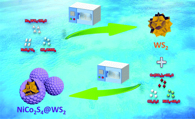
In Scheme 1, Na2WO4·2H2O, CH3CSNH2, NaH2PO2 and H2O were synthesized into spinous spherical WS by the one-pot hydrothermal method, and then the raw materials of WS and NCS were synthesized by the one-pot hydrothermal method to prepare the core–shell structure composite photocatalyst with the core of WS and shell of NCS. Because the core–shell structure was constructed by hydrothermal method through in situ growth, NCS had a relatively tight coating on WS, which would shorten the transfer path of the carriers and greatly accelerate the transfer rate of the carriers.3.1 Crystal structure and morphology analysis
According to the XRD pattern in Fig. 1a, it can be observed that the diffraction peaks of NCS and cubic phase NiCo2S4 (PDF#20-0782) correspond well, and the diffraction peaks are narrow and sharp and have no impurities, which proves that it has good crystallinity and no impurities appear. In the XRD pattern of WS, strong diffraction peaks attributed to (002), (004), (100) and (110) were found, corresponding to the hexagonal crystal system WS2, which was consistent with previous reports.15 The diffraction peak belonging to the cubic phase NiCo2S4 can be clearly observed in the synthesized composite photocatalyst. Due to the high background of NCS, some weak diffraction peaks belonging to WS can be observed. The results showed that the NCS@WS composite photocatalyst was successfully synthesized by hydrothermal method. According to the phase information, the three-dimensional unit cell structure pictures of NCS (Fig. 1b) and WS (Fig. 1c) were obtained. The Bravais unit cell parameters of the cubic phase NCS and hexagonal phase WS were a = b = c = 9.387 Å, α = β = γ = 90° and a = b = 3.154 Å, c = 12.362 Å, α = β = 90°, γ = 120°. NCS has played an important role in heterostructures due to its superior electron transport capability, which will be reflected in the following performance tests.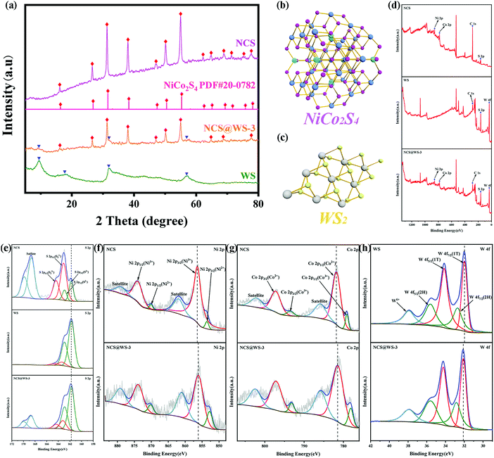 | ||
| Fig. 1 (a) XRD patterns of NCS, WS and NCS@WS-3; unit cell images of (b) NCS and (c) WS; XPS spectra of NCS, WS and NCS@WS-3: (d) survey spectrum, (e) S 2p, (f) Ni 2p, (g) Co 2p and (h) W 4f. | ||
After XPS characterization of the photocatalyst, the presence of elements contained in the photocatalyst could be observed in the survey spectrum (Fig. 1d). Fine spectra of Ni, Co, W and S elements were obtained by charge correction based on the peak position of C 1s at 284.8 eV. The S element spectra of NCS, WS and NCS@WS-3 were compared and found to have almost the same binding energy positions. From the fine spectrum of the S element of NCS (Fig. 1e), it could be found that the spin splitting peaks with binding energy positions of 161.78 eV and 162.94 eV corresponded to the existence of S2−,30 and the binding energy positions of the spin splitting peaks corresponding to S22− were 163.11 eV and 164.41 eV.31 The peaks occurring at 168.63 eV and 169.86 eV were attributed to sulfate produced by redox reaction during the synthesis of NCS.10 During the synthesis of WS, the valence state of the S element hardly changed, so no corresponding sulfate peak was observed in the fine spectrum of the S element of WS. For the fine spectrum of the Ni 2p element of NCS (Fig. 1f), the spin splitting peaks of 853.60 eV, 870.12 eV and 856.45 eV corresponded to Ni(II) and Ni(III), respectively. Both valence states exist in the NCS lattice, and the peak of the Co element was similar to it and accompanied by a pair of satellite peaks.32,33 In the fine spectrum of the NCS Co 2p element (Fig. 1g), the peaks of 779.11 eV, 793.55 eV and 781.81 eV, and 797.31 eV corresponded to Co(III) and Co(II), respectively. The synergistic effect of nickel and cobalt ions with abundant valence states in NCS provided abundant redox active sites compared to single metal sulfides. By comparing the fine spectrum of Ni 2p and Co 2p elements of NCS with NCS@WS-3, it was found that the peak position of NCS was obviously shifted to the direction of low binding energy. By observing the elemental fine spectrum of W 4f (Fig. 1h), it could be found that there were two peaks corresponding to the WS2 2H-phase at 32.74 eV and 35.64 eV. Some of them transferred to 32.74 eV and 35.64 eV for low binding energy, and converted from the semiconductor 2H-phase to the metal 1T-phase, forming a 1T/2H mixed phase WS.34 By comparing the fine spectrum of W 4f element between WS and NCS@WS-3, it was found that the peak position had shifted towards the higher binding energy. The binding energy displacement of the Ni, Co and W elements indicated that there was a strong interaction between NCS and WS, and they were closely connected with each other due to the formation of heterogeneous structures, rather than the simple physical interface contact. A major reason for this phenomenon is that the composite photocatalyst was synthesized by hydrothermal deposition of NCS in situ on the surface of WS, rather than simply mixing the two physically. The direction of the binding energy displacement of the element also indicated that the electron was transferred from NCS to WS.35,36 The direction of the electron transfer provided proof for the construction of the following heterojunction mechanism.
As can be seen in Fig. 2a, NCS presents nanoparticles with a diameter of about 300–500 nm, while in Fig. 2b, WS presents regular and angular flower spheres with a diameter of 4–7 μm. It could be clearly seen from Fig. 2c that NCS was coated in situ on the surface of WS after hydrothermal deposition, and formed a uniform core–shell structure with WS core and NCS shell layer. The TEM test result of the NCS@WS core–shell composite photocatalyst (Fig. 2d) showed the successful preparation of a spherical core–shell structure, and the morphology and size were mutually verified with SEM. Lattice fringes of 0.27 nm, 0.17 nm and 0.33 nm could be clearly observed in the HRTEM image of NCS@WS-3 (Fig. 2e), corresponding to (100) of WS, (440) and (220) of NCS, respectively. The element mapping image of NCS@WS-3 (Fig. 2(g–j)) in the region shown in Fig. 2f showed that the Ni, Co, S and W elements were evenly distributed in the detected region, and the W element was concentrated in the catalyst region with a core–shell structure, further confirming the successful synthesis of the core–shell structure.
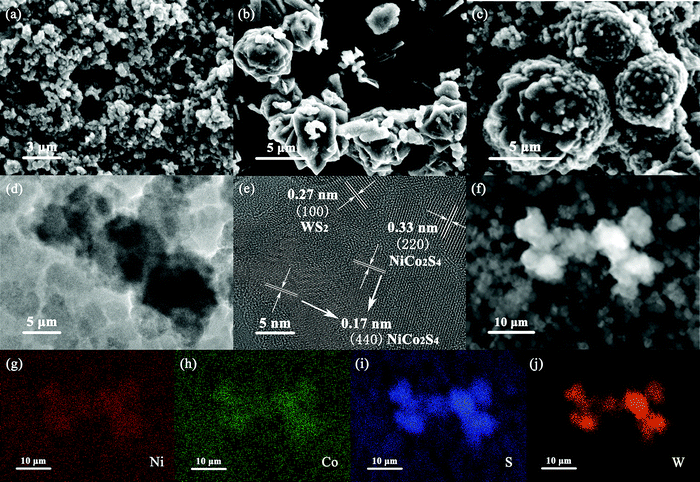 | ||
| Fig. 2 SEM images of (a) NCS, (b) WS, (c) NCS@WS-3; (d) TEM image and (e) HRTEM image of NCS@WS-3; (f–j) element mapping images of NCS@WS-3. | ||
3.2 Photocatalytic hydrogen production and BET analysis
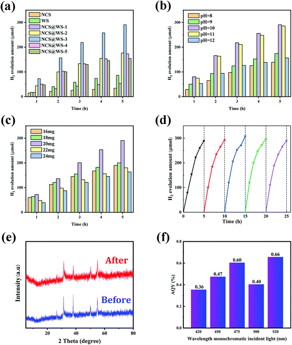
NCS@WS composite photocatalysts in different proportions were prepared by hydrothermal method with different masses of NiCl2·6H2O, Co(NO3)2·6H2O, CH4N2S (Table 1) mixed with 100 mg WS and 70 mL water. Fig. 3a shows the comparison of the hydrogen evolution amount of NCS, WS and NCS@WS in different proportions. The total hydrogen evolution amount of the composite photocatalyst within 5 h reached 290.70 μmol, and the hydrogen evolution rate was about 5.814 mmol g−1 h−1, which was much higher than the total hydrogen evolution amount of WS and NCS. It was 8.55 times the total hydrogen evolution of NCS (34.00 μmol) and 3.35 times the total hydrogen evolution of WS (86.70 μmol). When the proportion of NCS decreased, the hydrogen evolution reaction activity decreased because large areas of WS were exposed when the amount of NCS coated on the surface was small, and the incomplete core–shell structure led to the weakening of the core–shell synergistic effect. Conversely, excessive shell NCS could also reduce the hydrogen evolution by severely shielding WS, blocking the charge transport channels and closing the pores.37,38 The pH of the hydrogen evolution environment in which the catalyst was located was also an important factor affecting the effect of hydrogen evolution. Fig. 3b shows the comparison of the hydrogen evolution amount of the NCS@WS-3 catalyst in different pH sacrifice agents (TEOA), and found the optimal pH environment for hydrogen production. When the pH was too low or too high, the hydrogen evolution effect of the composite catalyst would be reduced.39 Especially in a highly alkaline environment, the low concentration of H+ led to the failure of the EY-sensitized composite catalyst to fully reduce H+, so the amount of photocatalytic hydrogen evolution in the system would decrease when the pH was higher.40Fig. 3c shows that when the amount of EY was 20 mg, the hydrogen evolution effect of the photocatalyst reached the best. When EY was less than 20 mg, EY could not adsorb saturation on the surface of the NCS shell, which made it impossible to maximize its promoting effect on hydrogen evolution of the composite catalyst, thus leading to the decrease of hydrogen evolution.41 However, when EY was more than 20 mg, the excessive absorption of EY shields the photocatalyst from light absorption and the photocatalyst could not fully contact the reaction medium, thus inhibiting the hydrogen evolution reaction. Fig. 3d shows the cyclic stability test diagram of the catalyst under optimal reaction conditions, with the loss of TEOA and EY compensated after 5 h of each reaction. After the catalytic reaction, EY would be more closely adsorbed on the surface of the catalyst, so its hydrogen production had a slight increase. After 5 × 5 h hydrogen evolution cycles, it still had good catalytic activity. In Fig. 3e, the XRD patterns before and after reaction had no obvious change of diffraction peak, which further proved the structural stability of the photocatalyst. The results indicated that the coating of NCS on WS was uniform and stable, and the NCS@WS core–shell structure prepared by in situ hydrothermal method had good stability indeed. It can be seen from Fig. 3f that the photocatalyst had an approximate narrow-band AQY in the range of 420–520 nm, indicating that the photocatalyst could carry out the hydrogen evolution reaction in the visible light range.| Sample | NiCl2·6H2O (mg) | Co(NO3)2·6H2O (mg) | CH4N2S (mg) |
|---|---|---|---|
| NCS@WS-1 | 62.37 | 152.73 | 99.87 |
| NCS@WS-2 | 70.16 | 171.82 | 112.36 |
| NCS@WS-3 | 77.96 | 190.92 | 124.84 |
| NCS@WS-4 | 85.76 | 210.01 | 137.32 |
| NCS@WS-5 | 93.55 | 229.10 | 149.81 |
Fig. 4a shows the nitrogen (N2) isothermal adsorption–desorption curves of NCS, WS and NCS@WS-3. From the characteristics of the curves, they were all of IV-type isotherms with H3-type hysteresis loops. This indicated that the photocatalyst had an abundant mesoporous channel structure.36Table 2 shows that after photocatalyst coupling, the BET specific surface area of NCS@WS-3 (12.46 m2 g−1) was much larger than that of NCS (4.41 m2 g−1) and WS (2.43 m2 g−1). The larger specific surface area brought by the core–shell structure meant more surface active adsorption sites. Thus, it could contact the reaction medium more fully and carried out the transport of the carrier to enhance the effect of hydrogen evolution, which was consistent with the hydrogen evolution test results. The pore volume and average pore size of the photocatalyst corresponded to the pore size distribution curve in Fig. 4b, and were consistent with the BET specific surface area. The pore volume (0.0450 cm3 g−1) and the average pore diameter (12.81 nm) of NCS@WS-3 were both increased before coupling. It shows that the coupled NCS@WS-3 had a more abundant pore structure, and the photo-generated electron hole pair could contact and react with the medium molecules more easily.
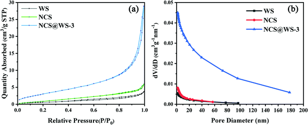 | ||
| Fig. 4 (a) BET nitrogen isothermal adsorption–desorption curves and (b) BJH pore size distribution of NCS, WS, and NCS@WS-3. | ||
| Sample | Specific surface area (m2 g−1) | Pore volume (cm3 g−1) | Pore diameter (nm) |
|---|---|---|---|
| WS | 2.43 | 0.0054 | 7.45 |
| NCS | 4.41 | 0.0084 | 6.34 |
| NCS@WS-3 | 12.46 | 0.0450 | 12.81 |
3.3 Photoelectric chemical performance analysis
In order to study the separation of the photo-generated electron hole pairs in photocatalyst, steady-state PL tests were carried out for EY solutions with different photocatalysts and pure EY solution. All solutions had obvious emission signals at 538 nm (Fig. 5a), among which the emission peak of the pure EY solution was the strongest, while the emission peak of the EY-NCS and EY-WS solution was somewhat weakened by comparison, which was due to fluorescence quenching between the photocatalyst and the EY molecules adsorbed on the surface of NCS and WS.42 When NCS@WS-3 was dissolved in EY solution for testing, the emission peak intensity reached the lowest, which undoubtedly indicated that the coupled core–shell photocatalyst led to a stronger fluorescence quenching phenomenon.43 This could effectively inhibit the recombination of the photo-generated carriers and make more photo-generated electrons participate in the reduction of H+. The TRF spectrum (Fig. 5b) of the photocatalysts was fitted to obtain the average fluorescence lifetime (Fig. 5c). The NCS@WS-3 core–shell photocatalyst had the shortest average fluorescence lifetime compared to WS and NCS, which means that the core–shell structure construction accelerates the transport of carriers between the photocatalysts, leading to stronger fluorescence quenching and thus lower average fluorescence lifetime.44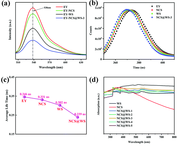 | ||
| Fig. 5 (a) Steady-state PL spectrum, (b) TRF spectrum, (c) average fluorescence lifetime spectrum and (d) UV-vis DRS spectrum of the photocatalysts. | ||
The UV-vis DRS spectrum in Fig. 5d shows that the light absorption performance of NCS@WS-3 was not significantly improved compared with those of NCS and WS. There is a good correlation between the absorption spectra of the composite photocatalyst and AQY. The absorption coefficients of the photocatalysts were very close in the UV light range, while in the visible light range, NCS had a lower absorption capacity than WS, and the composite photocatalysts were in between. Compared with the composite photocatalyst with different loading, the light absorption capacity did not change significantly. Obviously, the core–shell structure did not optimize the absorption capacity of the photocatalysts and broaden the absorption range, which means that no more photons were absorbed by the composite photocatalyst. Since the improvement of the hydrogen evolution effect cannot be attributed to the improvement of the light absorption capacity, it is necessary to further study the band structure and carrier transport of the photocatalyst.
In order to study the transfer and recombination of the photo-generated carriers before and after photocatalyst recombination, the electrochemical properties of the photocatalyst were characterized. In Fig. 6a, the I–T curves show that the ITO glass did not produce any current response under light, while the NCS@WS-3 core–shell composites showed a very strong photocurrent response compared with NCS and WS, indicating that the electron hole pairs of pure NCS and WS were easy to recombine, and the recombination probability was effectively reduced after recombination. This is consistent with the previous results of steady-state PL. In Fig. 6b, the LSV curves obtained from the photocatalyst test show that NCS@WS-3 had a lower overpotential than pure NCS and WS, which was due to the formation of a core–shell structure and the surface was easier for the hydrogen evolution reaction.45 In Fig. 6c, the EIS curves show that the arc radius of NCS@WS-3 was smaller than that of NCS and WS, indicating that the charge transfer resistance was smaller after recombination, and the construction of the heterojunction significantly improved the efficiency of the carrier transport and separation. Compared with pure NCS and WS, the photocatalyst after hydrothermal recombination undoubtedly improved the transmission rate and separation efficiency of the photo-generated carriers. In order to further study the carrier transmission mechanism, the band structure of the photocatalysts was analyzed.
 | ||
| Fig. 6 (a) Transient photocurrent response intensity–time (I–T), (b) linear sweep voltammetry (LSV) and (c) electrochemical impedance spectroscopy (EIS) curves of NCS, WS and NCS@WS-3 with ITO. | ||
3.4 Band structure analysis
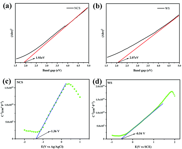
UV-vis DRS spectra data were processed to obtain the Tauc spectra of NCS (Fig. 7a) and WS (Fig. 7b) by Tauc plot method, and the band gaps of NCS and WS were 1.93 eV and 2.07 eV, respectively, after analysis. The wide absorption wavelength range measured for the photocatalysts was due to their narrow band gap, which also means that the recombination probability of the photo-generated carriers was increased. The number of photo-generated electrons available for the hydrogen evolution reaction by a single photocatalyst with a narrow band gap was small, which was not conducive to the generation of hydrogen. The flat band (Efb) potential of NCS and WS obtained from the MS curves were −1.36 eV (Fig. 7c) and −0.54 eV (Fig. 7d), and the slope of the curve was positive, indicating that both NCS and WS photocatalysts were n-type semiconductors, and the conduction band (CB) potential of the n-type semiconductors was generally 0.1 eV lower than the Efb potential.46| ENHE = Efb (Ag/AgCl) + 0.197 eV − 0.1 eV | (2) |
| ENHE = Efb (SCE) + 0.241 eV − 0.1 eV | (3) |
| EVB = ECB − Eg | (4) |
According to the different reference electrodes used in the test, the guide band positions of NCS and WS were calculated from (2) and (3) as −1.26 eV (vs. NHE) and −0.4 eV (vs. NHE).47 Then, according to their band gap values of 1.93 eV and 2.07 eV, the valence band (VB) positions of NCS and WS were calculated by (4) as 0.67 eV and 1.67 eV.48
Two possible carrier transfer mechanisms were proposed for the heterojunction formed by the composite photocatalyst. In Scheme 2a, the Type-II heterojunction shows that the photo-generated electrons and holes were transferred to more positive CB and more negative VB positions in the other photocatalyst, which caused the photo-generated carriers to accumulate in the two photocatalysts, respectively, thus reducing the probability of the recombination of the electron hole pairs. However, due to the repulsion between an electron and electron and between hole and hole, the transfer of carriers is hindered, and the lack of driving force for transfer makes the separation of carriers difficult to achieve effectively. In addition, due to the positive CB position and negative VB position, the accumulated electron and hole positions could not even meet the reduction potential requirements of H2/H+, which weakened the hydrogen evolution capacity of the photocatalyst. Compared with the Type-II heterojunction, the S-scheme heterojunction (Scheme 2b) recombines the electrons on the more negative CB with the holes on the more positive VB due to the driving force of the built electric field, which conforms to the gravitational interaction between electrons and holes in dynamics.23,49,50 In addition, this mechanism leads to a strong redox capacity after the accumulation of photo-generated carriers, which can improve the hydrogen evolution effect of the composite photocatalyst from the perspective of thermodynamics.
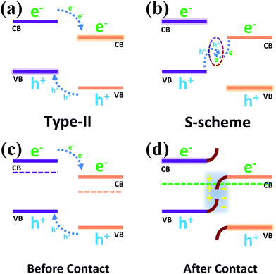 | ||
| Scheme 2 (a) Type-II heterojunction and (b) S-scheme heterojunction; schematic diagram of the energy band structure before contact (c) and after contact (d). | ||
Before the contact (Scheme 2c) of two separate photocatalysts, their Fermi levels (Ef) were close to the conduction band due to the properties of the n-type semiconductors.51–54 The Ef reached a balance after the contact (Scheme 2d) of the two semiconductors, resulting in band bending of NCS and WS, which promoted the recombination of the holes in the VB of NCS and the electrons in the CB of WS, so that photo-generated electrons and photo-generated holes could accumulate in the CB of NCS and the VB of WS. The spontaneous diffusion of electrons in NCS to WS after contact would lead to the formation of an electron depletion layer and accumulation layer, thus making NCS and WS have opposite charges and forming an internal electric field, which also exists as a driving force to promote the transfer of photo-generated charge carriers. The binding energy shift in the previous XPS characterization provided direct evidence for the migration of photo-generated electron holes across the NCS and WS interfaces, and combined with the electrostatic interaction at the semiconductor interface, the effective recombination of electron hole pairs with unique transport paths improved the carrier separation efficiency.
3.5 Mechanism
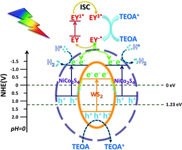
According to the above characterization data of the catalyst, the possible mechanism is proposed (Scheme 3): EY in the solution uniformly concentrates on the outer surface of the NCS shell, and is excited by light and then transitions to an excited state of EY1*, and then transitions to a triple excited state of EY3* through fast intersystem crossing (ISC).55 After EY3* contacts with TEOA, the electrons obtained are reduced to EY−*, and TEOA loses electrons to an oxidation state. The electrons lost due to the conversion of EY−* adsorbed on the surface of the NCS shell into EY and the electrons generated due to the intrinsic excitation gather at the CB position of the NCS.56 The H+ free in H2O is adsorbed on the surface of NCS and then is reduced to H2 by photo-generated electrons in its CB, and TEOA serves as an electron sacrifice agent to consume the holes. The unique in situ grown core–shell structure enabled WS and NCS to have shorter electron transfer paths and faster charge transfer efficiency. After the electrons in the CB of WS were recombined with the holes in the VB of NCS, the recombination efficiency of photo-generated carriers of NCS and WS is greatly reduced. The remaining photo-generated electrons and holes accumulated in the CB of NCS and the VB of WS, respectively. The more negative CB potential and the more positive VB potential indicated stronger redox ability, and the photo-generated electrons were more likely to reduce H+ to H2 for release.4 Conclusion
A NCS@WS core–shell photocatalyst was prepared by a two-step in situ hydrothermal method. PL and photochemical characterization confirmed that the composite photocatalyst can effectively improve the separation efficiency of the photo-generated carriers. The BET test results showed that the specific surface area increased after the formation of the core–shell structure, which could provide more active adsorption sites for the reaction medium. The transfer direction of the binding energy of the XPS element fine spectra was used to determine the charge transport path in the composite catalyst. According to these data, the photo-generated charge carrier of NCS@WS was determined to transmit according to the S-scheme path, which realized the effective separation of the photo-generated electrons and photo-generated holes, and greatly reduced the recombination probability. Under the optimal conditions, the total hydrogen evolution amount of NCS@WS reached 290.70 μmol and the rate of the hydrogen evolution was about 5.814 mmol g−1 h−1, which was 8.55 times that of NCS and 3.35 times that of WS. It has proved that the construction of the S-scheme heterojunction with core–shell structure is beneficial to improve the recombination of the photo-generated carriers, increase the specific surface area, and effectively enhance the performance of the photocatalytic hydrogen evolution. This method provided an idea for seeking an efficient hydrogen production system.Conflicts of interest
There are no conflicts to declare.Acknowledgements
This work was supported by the Fundamental Research Funds for the Central Universities of North University for Nationalities (2021KJCX02), the Natural Science Foundation of Ningxia Province (2021AAC03180), and also was supported by the Xixia District Science and Technology Plan Project (XXKJ1901).References
- A. Fujishima and K. Honda, Electrochemical photolysis of water at a semiconductor electrode, Nature, 1972, 238, 37–38 CrossRef CAS.
- X. Chen and S. S. Mao, Titanium dioxide nanomaterials: synthesis, properties, modifications, and applications, Chem. Rev., 2007, 107, 2891–2959 CrossRef CAS.
- J. Ran, J. Yu and M. Jaroniec, Ni(OH)2 modified CdS nanorods for highly efficient visible-light-driven photocatalytic H2 generation, Green Chem., 2011, 13, 2708–2713 RSC.
- K. Maeda, T. Takata, M. Hara, N. Saito, Y. Inoue, H. Kobayashi and K. Domen, GaN
![[thin space (1/6-em)]](https://www.rsc.org/images/entities/char_2009.gif) :
:![[thin space (1/6-em)]](https://www.rsc.org/images/entities/char_2009.gif) ZnO solid solution as a photocatalyst for visible-light-driven overall water splitting, J. Am. Chem. Soc., 2005, 127, 8286–8287 CrossRef CAS PubMed.
ZnO solid solution as a photocatalyst for visible-light-driven overall water splitting, J. Am. Chem. Soc., 2005, 127, 8286–8287 CrossRef CAS PubMed. - Z. Yin, B. Chen, M. Bosman, X. Cao, J. Chen, B. Zheng and H. Zhang, Au Nanoparticle-Modified MoS2 Nanosheet-Based Photoelectrochemical Cells for Water Splitting, Small, 2014, 10, 3537–3543 CrossRef CAS.
- R. Shen, Y. Ding, S. Li, P. Zhang, Q. Xiang, Y. H. Ng and X. Li, Constructing low-cost Ni3C/twin-crystal Zn0.5Cd0.5S heterojunction/homojunction nanohybrids for efficient photocatalytic H2 evolution, Chin. J. Catal., 2021, 42, 25–36 CrossRef CAS.
- R. Shen, Z. Liang, H. Ng Yun, P. Zhang, Q. Xiang and X. Li, A review on 2D MoS2 cocatalysts in photocatalytic H2 production, J. Mater. Sci. Technol., 2020, 56, 89–121 CrossRef.
- C. Wang, X. Ma, Z. Fu, X. Hu, J. Fan and E. Liu, Highly efficient photocatalytic H2 evolution over NiCo2S4/Mn0.5Cd0.5S: bulk twinned homojunctions and interfacial heterojunctions, J. Colloid Interface Sci., 2021, 592, 66–76 CrossRef CAS PubMed.
- K. Jiang, W. Iqbal, B. Yang, M. Rauf, I. Ali, X. Lu and Y. Mao, Noble metal-free NiCo2S4/CN sheet-on-sheet heterostructure for highly efficient visible-light-driven photocatalytic hydrogen evolution, J. Alloys Compd., 2021, 853, 157284 CrossRef CAS.
- S. Zhao, J. Xu, M. Mao, L. J. Li and X. H. Li, NiCo2S4@Zn0.5Cd0.5S with direct Z-scheme heterojunction constructed by band structure adjustment of ZnxCd1−xS for efficient photocatalytic H2 evolution, Appl. Surf. Sci., 2020, 528, 12 Search PubMed.
- P. Kulkarni, S. K. Nataraj, R. G. Balakrishna, D. H. Nagaraju and M. V. Reddy, Nanostructured binary and ternary metal sulfides: synthesis methods and their application in energy conversion and storage devices, J. Mater. Chem. A, 2017, 5, 22040–22094 RSC.
- S. N. Tiruneh, B. K. Kang, S. H. Kwag, Y. Lee, M. Kim and D. H. Yoon, Synergistically Active NiCo2S4 Nanoparticles Coupled with Holey Defect Graphene Hydrogel for High-Performance Solid-State Supercapacitors, Chem. – Eur. J., 2018, 24, 3263–3270 CrossRef CAS.
- Z. Yuan, A. Zhang, D. Jiang, N. Mao, J. Tian, W. Huang, R. Liu and J. Liu, Hollow 3D Frame Structure Modified with NiCo2S4 Nanosheets and Spinous Fe2O3 Nanowires as Electrode Materials for High-Performance All-Solid-State Asymmetric Supercapacitors, Chem. – Eur. J., 2020, 26, 4790–4797 CrossRef CAS.
- Z. Liang, S. Yang, X. Wang, H. Cui, X. Wang and J. Tian, The metallic 1T-phase WS2 nanosheets as cocatalysts for enhancing the photocatalytic hydrogen evolution of g-C3N4 nanotubes, Appl. Catal., B, 2020, 274, 119114 CrossRef CAS.
- Q. Ruan, H. Wang, H. Lin, Y. Li, Y. Geng and L. Wang, Unique ternary Cd0.85Zn0.15S@WO3/WS2 core-shell nanorods for highly-efficient photocatalytic H2 evolution under visible-light irradiation, Int. J. Hydrogen Energy, 2020, 45, 27160–27170 CrossRef CAS.
- S. Hussain, M. Faizan, D. Vikraman, I. Rabani, B. Ali, H.-S. Kim, J. Jung and K.-W. Nam, Eutectoid WxC embedded WS2 nanosheets as a hybrid composite anode for lithium-ion batteries, Ceram. Int., 2021, 47, 18646–18655 CrossRef CAS.
- C. Yang, N. Gong, T. Chen, Y. Li, W. Peng, F. Zhang and X. Fan, Enhanced catalytic conversion of polysulfides using high-percentage 1T-phase metallic WS2 nanosheets for Li–S batteries, Green Energy & Environment, 2021 Search PubMed.
- M. A. Dwiputra, F. Fadhila, C. Imawan and V. Fauzia, The enhanced performance of capacitive-type humidity sensors based on ZnO nanorods/WS2 nanosheets heterostructure, Sens. Actuators, B, 2020, 310, 127810 CrossRef CAS.
- M. M. Sajid, S. B. Khan, Y. Javed, N. Amin, N. Akhtar Shad, Z. Zhang, M. Imran Yousaf, M. Sarwar and H. Zhai, Synthesis of novel visible light assisted Pt doped zinc vanadate (Pt/Zn4V2O9) for enhanced photocatalytic properties, Chem. Phys., 2020, 539, 110980 CrossRef CAS.
- Z. Li, D. Jin and Z. Wang, ZnO/CdSe-diethylenetriamine nanocomposite as a step-scheme photocatalyst for photocatalytic hydrogen evolution, Appl. Surf. Sci., 2020, 529, 147071 CrossRef CAS.
- T.-F. Yeh, C.-Y. Teng, S.-J. Chen and H. Teng, Nitrogen-Doped Graphene Oxide Quantum Dots as Photocatalysts for Overall Water-Splitting under Visible Light Illumination, Adv. Mater., 2014, 26, 3297–3303 CrossRef CAS.
- J. Wei, Y. Chen, H. Zhang, Z. Zhuang and Y. Yu, Hierarchically porous S-scheme CdS/UiO-66 photocatalyst for efficient 4-nitroaniline reduction, Chin. J. Catal., 2021, 42, 78–86 CrossRef CAS.
- F. Xu, K. Meng, B. Cheng, S. Wang and J. Yu, Unique S-scheme heterojunctions in self-assembled TiO2/CsPbBr3 hybrids for CO2 photoreduction, Nat. Commun., 2020, 11, 4613 CrossRef CAS PubMed.
- Y. Jia, Z. Wang, X.-Q. Qiao, L. Huang, S. Gan, D. Hou, J. Zhao, C. Sun and D.-S. Li, A synergistic effect between S-scheme heterojunction and Noble-metal free cocatalyst to promote the hydrogen evolution of ZnO/CdS/MoS2 photocatalyst, Chem. Eng. J., 2021, 424, 130368 CrossRef CAS.
- L. Zhou, Y. Li, S. Yang, M. Zhang, Z. Wu, R. Jin and Y. Xing, Preparation of novel 0D/2D Ag2WO4/WO3 Step-scheme heterojunction with effective interfacial charges transfer for photocatalytic contaminants degradation and mechanism insight, Chem. Eng. J., 2021, 420, 130361 CrossRef CAS.
- J. Peng, J. Shen, X. Yu, H. Tang, Zulfiqar and Q. Liu, Construction of LSPR-enhanced 0D/2D CdS/MoO3−xS-scheme heterojunctions for visible-light-driven photocatalytic H2 evolution, Chin. J. Catal., 2021, 42, 87–96 CrossRef CAS.
- X. Fang, J. Wang, Y. Yu, S. Kang and L. Cui, Self-assembled CdS@BN core-shell photocatalysts for efficient visible-light-driven photocatalytic hydrogen evolution, Int. J. Hydrogen Energy, 2020, 45, 14841–14848 CrossRef CAS.
- P. Ravi, V. N. Rao, M. V. Shankar and M. Sathish, CuO@NiO core-shell nanoparticles decorated anatase TiO2 nanospheres for enhanced photocatalytic hydrogen production, Int. J. Hydrogen Energy, 2020, 45, 7517–7529 CrossRef CAS.
- D. Ren, Z. Liang, Y. H. Ng, P. Zhang, Q. Xiang and X. Li, Strongly coupled 2D–2D nanojunctions between P-doped Ni2S (Ni2SP) cocatalysts and CdS nanosheets for efficient photocatalytic H2 evolution, Chem. Eng. J., 2020, 390, 124496 CrossRef CAS.
- G. M. Bremmer, L. van Haandel, E. J. M. Hensen, J. W. M. Frenken and P. J. Kooyman, The effect of oxidation and resulfidation on (Ni/Co)MoS2 hydrodesulfurisation catalysts, Appl. Catal., B, 2019, 243, 145–150 CrossRef CAS.
- J. Hou, Y. Lei, F. Wang, X. Ma, S. Min, Z. Jin and J. Xu, In situ photochemical fabrication of transition metal-promoted amorphous molybdenum sulfide catalysts for enhanced photosensitized hydrogen evolution, Int. J. Hydrogen Energy, 2017, 42, 11118–11129 CrossRef CAS.
- W. Liu, J. Zhang, Z. Bai, G. Jiang, M. Li, K. Feng, L. Yang, Y. Ding, T. Yu, Z. Chen and A. Yu, Controllable Urchin-Like NiCo2S4 Microsphere Synergized with Sulfur-Doped Graphene as Bifunctional Catalyst for Superior Rechargeable Zn–Air Battery, Adv. Funct. Mater., 2018, 28, 1706675 CrossRef.
- Y. Wu, X. Liu, D. Han, X. Song, L. Shi, Y. Song, S. Niu, Y. Xie, J. Cai and S. Wu, Electron density modulation of NiCo2S4 nanowires by nitrogen incorporation for highly efficient hydrogen evolution catalysis, Nat. Commun., 2018, 9, 1425 CrossRef.
- D. Vikraman, S. Hussain, M. Ali, K. Karuppasamy, P. Santhoshkumar, J.-H. Hwang, J. Jung and H.-S. Kim, Theoretical evaluation and experimental investigation of layered 2H/1T-phase MoS2 and its reduced graphene-oxide hybrids for hydrogen evolution reactions, J. Alloys Compd., 2021, 868, 159272 CrossRef CAS.
- Z. Wang, Y. Chen, L. Zhang, B. Cheng, J. Yu and J. Fan, Step-scheme CdS/TiO2 nanocomposite hollow microsphere with enhanced photocatalytic CO2 reduction activity, J. Mater. Sci. Technol., 2020, 56, 143–150 CrossRef.
- F. He, B. Zhu, B. Cheng, J. Yu, W. Ho and W. Macyk, 2D/2D/0D TiO2/C3N4/Ti3C2 MXene composite S-scheme photocatalyst with enhanced CO2 reduction activity, Appl. Catal., B, 2020, 272, 119006 CrossRef CAS.
- P. Liu, S. Gao, Y. Wang, Y. Huang, W. He, W. Huang and J. Luo, Carbon nanocages with N-doped carbon inner shell and Co/N-doped carbon outer shell as electromagnetic wave absorption materials, Chem. Eng. J., 2020, 381, 122653 CrossRef CAS.
- X. Guo, M. Li, Y. Liu, Y. Huang, S. Geng, W. Yang and Y. Yu, Hierarchical core-shell electrode with NiWO4 nanoparticles wrapped MnCo2O4 nanowire arrays on Ni foam for high-performance asymmetric supercapacitors, J. Colloid Interface Sci., 2020, 563, 405–413 CrossRef CAS.
- D. Ren, R. Shen, Z. Jiang, X. Lu and X. Li, Highly efficient visible-light photocatalytic H2 evolution over 2D–2D CdS/Cu7S4 layered heterojunctions, Chin. J. Catal., 2020, 41, 31–40 CrossRef CAS.
- J. Shi, F. Chen, L. Hou, G. Li, Y. Li, X. Guan, H. Liu and L. Guo, Eosin Y bidentately bridged on UiO-66-NH2 by solvothermal treatment towards enhanced visible-light-driven photocatalytic H2 production, Appl. Catal., B, 2021, 280, 119385 CrossRef CAS.
- Y. Liu, X. Hao, H. Hu and Z. Jin, High Efficiency Electron Transfer Realized over NiS2/MoSe2S-Scheme Heterojunction in Photocatalytic Hydrogen Evolution, Acta Phys.-Chim. Sin., 2021, 37, 2008030 Search PubMed.
- R. Shen, D. Ren, Y. Ding, Y. Guan, Y. H. Ng, P. Zhang and X. Li, Nanostructured CdS for efficient photocatalytic H2 evolution: a review, Science China, Materials, 2020, 63, 2153–2188 CAS.
- P. S. Basavarajappa, S. B. Patil, N. Ganganagappa, K. R. Reddy, A. V. Raghu and C. V. Reddy, Recent progress in metal-doped TiO2, non-metal doped/codoped TiO2 and TiO2 nanostructured hybrids for enhanced photocatalysis, Int. J. Hydrogen Energy, 2020, 45, 7764–7778 CrossRef CAS.
- P. Xia, S. Cao, B. Zhu, M. Liu, M. Shi, J. Yu and Y. Zhang, Designing a 0D/2D S-Scheme Heterojunction over Polymeric Carbon Nitride for Visible-Light Photocatalytic Inactivation of Bacteria, Angew. Chem., Int. Ed., 2020, 59, 5218–5225 CrossRef CAS.
- Q. C. Zhimin Jiang, Q. Zheng, R. Shen, P. Zhang and X. Li, Constructing 1D/2D Schottky-Based Heterojunctions between Mn0.2Cd0.8S Nanorods and Ti3C2 Nanosheets for Boosted Photocatalytic H2 Evolution, Acta Phys.-Chim. Sin., 2021, 37, 2010059 Search PubMed.
- L. Zhang and Z. Jin, Theoretically guiding the construction of a novel Cu2O@Cu97P3@Cu3P heterojunction with a 3D hierarchical structure for efficient photocatalytic hydrogen evolution, Nanoscale, 2021, 13, 1340–1353 RSC.
- G. Ai, H. Li, S. Liu, R. Mo and J. Zhong, Solar Water Splitting by TiO2/CdS/Co–Pi Nanowire Array Photoanode Enhanced with Co–Pi as Hole Transfer Relay and CdS as Light Absorber, Adv. Funct. Mater., 2015, 25, 5706–5713 CrossRef CAS.
- Y. Peng, Q.-G. Chen, D. Wang, H.-Y. Zhou and A.-W. Xu, Synthesis of one-dimensional WO3–Bi2WO6 heterojunctions with enhanced photocatalytic activity, CrystEngComm, 2015, 17, 569–576 RSC.
- J. Fu, Q. Xu, J. Low, C. Jiang and J. Yu, Ultrathin 2D/2D WO3/g-C3N4 step-scheme H2-production photocatalyst, Appl. Catal., B, 2019, 243, 556–565 CrossRef CAS.
- Q. Xu, L. Zhang, B. Cheng, J. Fan and J. Yu, S-Scheme Heterojunction Photocatalyst, Chemistry, 2020, 6, 1543–1559 CrossRef CAS.
- W. Xue, W. Chang, X. Hu, J. Fan and E. Liu, 2D mesoporous ultrathin Cd0.5Zn0.5S nanosheet: fabrication mechanism and application potential for photocatalytic H2 evolution, Chin. J. Catal., 2021, 42, 152–163 CrossRef CAS.
- Y. Lu, Z. Zhang, X. Liu, W. Wang, T. Peng, P. Guo, H. Sun, H. Yan and Y. Luo, NiCo2S4/carbon nanotube nanocomposites with a chain-like architecture for enhanced supercapacitor performance, CrystEngComm, 2016, 18, 7696–7706 RSC.
- B. Mahler, V. Hoepfner, K. Liao and G. A. Ozin, Colloidal Synthesis of 1T-WS2 and 2H-WS2 Nanosheets: applications for Photocatalytic Hydrogen Evolution, J. Am. Chem. Soc., 2014, 136, 14121–14127 CrossRef CAS PubMed.
- W. Ho, J. C. Yu, J. Lin, J. Yu and P. Li, Preparation and photocatalytic behavior of MoS2 and WS2 nanocluster sensitized TiO2, Langmuir, 2004, 20, 5865–5869 CrossRef CAS.
- L. Yang, J. Huang, L. Shi, L. Cao, W. Zhou, K. Chang, X. Meng, G. Liu, Y. Jie and J. Ye, Efficient hydrogen evolution over Sb doped SnO2 photocatalyst sensitized by Eosin Y under visible light irradiation, Nano Energy, 2017, 36, 331–340 CrossRef CAS.
- J. Luo, Z. Lin, Y. Zhao, S. Jiang and S. Song, The embedded CuInS2 into hollow-concave carbon nitride for photocatalytic H2O splitting into H2 with S-scheme principle, Chin. J. Catal., 2020, 41, 122–130 CrossRef CAS.
| This journal is © The Royal Society of Chemistry and the Centre National de la Recherche Scientifique 2022 |

