
 Open Access Article
 This Open Access Article is licensed under a Creative Commons Attribution-Non Commercial 3.0 Unported Licence
Nanoscale biophysical properties of small extracellular vesicles from senescent cells using atomic force microscopy, surface potential microscopy, and Raman spectroscopy†
Hyo Gyeong
Lee‡
a,
Seokbeom
Roh‡
bc,
Hyun Jung
Kim
bd,
Seokho
Kim
 e,
Yoochan
Hong
*d,
Gyudo
Lee
*bc and
Ok Hee
Jeon
*a
e,
Yoochan
Hong
*d,
Gyudo
Lee
*bc and
Ok Hee
Jeon
*a
aDepartment of Biomedical Sciences, Korea University College of Medicine, Seoul 02841, Republic of Korea. E-mail: ojeon@korea.ac.kr
bDepartment of Biotechnology and Bioinformatics, Korea University, Sejong 30019, Republic of Korea. E-mail: lkd0807@korea.ac.kr
cInterdisciplinary Graduate Program for Artificial Intelligence Smart Convergence Technology, Korea University, Sejong 30019, Republic of Korea
dDepartment of Medical Device, Korea Institute of Machinery and Materials (KIMM), Daegu 42994, Republic of Korea. E-mail: ychong1983@kimm.re.kr
eAnimal Biotechnology Division, National Institute of Animal Science, Rural Development Administration, Wanju 55365, Republic of Korea
First published on 8th September 2022
Abstract
Cells secrete extracellular vesicles (EVs) carrying cell-of-origin markers to communicate with surrounding cells. EVs regulate physiological processes ranging from intercellular signaling to waste management. However, when senescent cells (SnCs) secrete EVs, the EVs, which are newly regarded as senescence-associated secretory phenotype (SASP) factors, can evoke inflammation, senescence induction, and metabolic disorders in neighboring cells. Unlike other soluble SASP factors, the biophysical properties of EVs, including small EVs (sEVs), derived from SnCs have not yet been investigated. In this study, sEVs were extracted from a human IMR90 lung fibroblast in vitro senescence model. Their biomechanical properties were mapped using atomic force microscopy-based quantitative nanomechanical techniques, surface potential microscopy, and Raman spectroscopy. The surfaces of sEVs derived from SnCs are slightly stiffer but their cores are softer than those of sEVs secreted from non-senescent cells (non-SnCs). This inversely proportional relationship between deformation and stiffness, attributed to a decrease in the concentration of genetic and protein materials inside the vesicles and the adsorption of positively charged SASP factors onto the vesicle surfaces, respectively, was found to be a peculiar characteristic of SnC-derived sEVs. Our results demonstrate that the biomechanical properties of SnC-derived sEVs differ from those of non-SnC-derived sEVs and provide insight into the mechanisms underlying their formation and composition.
New conceptsCells communicate with extracellular vesicles (EVs) each other, while senescent cells (SnCs) do likewise but spread their senescence-associated secretory phenotypes (SASPs) to neighboring cells. However, it has been veiled how much the biophysical properties of EVs from non-SnCs and SnCs differ. This question is quite fundamental to the study of cellular aging but has not yet been revealed at the nanoscale level. We applied atomic force microscopy (AFM) and Raman spectroscopy to solve this critical question of aging. We discovered the following biophysical features of SnC-derived EVs through AFM-based quantitative nanomechanical techniques, surface potential microscopy, and Raman spectroscopy. The surfaces of EVs derived from SnCs have harder, but their interiors are softer than those of EVs secreted from non-SnCs. This strange relationship between deformation and stiffness in SnC-derived EVs was attributed to a decrease in genetic and protein materials inside the vesicle and the adsorption of positively charged SASP factors onto the vesicle surface. Our findings show that the biophysical and nanomechanical properties of SnC-derived EVs differ from those of non-SnC-derived EVs and provide insights into the mechanisms driving their formation and composition. |
Introduction
The main role of cellular senescence (“cellular aging”) is to irreversibly prevent the expansion of damaged cells by exposure to multiple types of stress such as telomere shortening, DNA damage, and aberrant oncogene activation, or parallelly, to facilitate tissue repair.1 However, during aging or with persistent damage, senescent cells (SnCs) accumulate in various tissues in mice and humans; thus, SnCs are known to be key drivers of a host of age-related phenotypes and pathologies.2,3 Importantly, SnCs secrete not only various soluble proteins, such as proinflammatory cytokines, chemokines, extracellular proteases, and growth factors,4–6 but also senescence-associated extracellular vesicles (EVs),7–10 regarded as new senescence-associated secretory phenotype (SASP) factors.EVs are heterogeneous populations of membrane-limited particles, comprising microvesicles and exosomes. Microvesicles are large EVs (lEVs, 100–1000 nm) that bud directly from the plasma membrane, and exosomes are small, nanosized EVs (sEVs, 30–200 nm) of endocytic origin.11–14 sEVs (mainly exosomes) are abundant in body fluids and carry genetic and molecular information, such as DNA, RNA, lipids, proteins of cellular origin, and pathological cell and tissue phenotypes.15 In particular, senescence-associated sEVs (or sEVs derived from SnCs) contain RNA and protein compositions distinct from those derived from normal cells, and these are dependent on the cell-type and senescence inducer.7,16 Further, SnC-derived sEVs transfer these components to propagate the senescent phenotype to nearby normal cells and abnormally regulate their cellular functions.16 sEVs can therefore be utilized as biomarkers for senescence, particularly in age-related illnesses in which SnCs are present.
To date, reliable markers for detecting SnC-derived sEVs remain obscure. Furthermore, targeting senescence-related markers in sEVs is a challenge. Standard methods, such as fluorescence-activated cell sorting, western blotting, and enzyme-linked immunosorbent assays, are currently used to detect common sEV markers (e.g., CD63, CD81, ALIX, and TSG101). These markers have been co-opted as biomarkers for SnC-derived sEVs. Beyond these efforts, the stereoscopic characteristics of the biophysical patterns of SnC-derived sEVs are thought to contain comprehensive information on multiple possible indicators, without focusing on any single marker. Although the biophysical properties of sEVs released by cells are altered by external stimuli or in tumorigenic processes,17 the characteristics of sEVs secreted by SnCs need to be further elucidated.
Unveiling the biophysical characteristics of SnC-derived sEVs may help in better understanding their biological functions, such as cellular adhesion, exo/endocytosis, cellular uptake,18–20 and potentially the transmission of cellular senescence. Here, we demonstrate the potential screening probability for differences between sEVs secreted by ionizing radiation (IR)-induced SnCs and quiescent control cells (non-SnCs) using atomic force microscopy (AFM), surface potential microscopy, and Raman spectroscopy. The AFM application PeakForce quantitative nanomechanics (PF-QNM)21–23 was used to investigate the nanomechanical properties of SnC-derived sEVs. Moreover, Kelvin probe force microscopy (KPFM),24–27 also known as surface potential microscopy, was used to estimate the electrostatic surface potential of SnC-derived sEVs and compare it with that of non-SnC-derived sEVs.
The combination of these two AFM techniques (PF-QNM and KPFM) revealed that, based on their biophysical properties, SnC-derived sEVs have the characteristics of the dessert crème brûlée (i.e., they are harder on the outside and softer on the inside). Along with these physico-mechanical signatures, alterations in the molecular composition between the two groups of sEVs were identified using Raman spectroscopy28 to support the KPFM surface potential data. According to the drift of the Raman spectra and clustering by principal component analysis (PCA), definite differences were observed in the charges of SnC- and non-SnC-derived sEVs. Using capture platforms for SnC- and non-SnC-derived sEVs and staining their protein cargos, potential SASP protein factors were identified in the sEVs that may contribute to their distinct biophysical and biochemical characteristics at the nanoscale.
Results and discussion
Development of an in vitro senescence model
To investigate the characteristic nanomechanical and biophysical fingerprints of SnC-derived EVs, we employed a well-established in vitro model of IR-induced senescence in human IMR90 lung fibroblasts for the SnC-derived EVs. We cultured quiescent non-SnCs for three days in 0.2% serum media to control the growth status of the non-SnC-derived EVs. Senescence induction was first evaluated using the biochemical hallmarks of senescence. Ten days after 20 Gy X-ray irradiation, the cells (SnCs) developed various senescent phenotypes, including (1) enhanced SA-β-gal activity29 (Fig. 1(A)); (2) reduced EdU incorporation (a measure of nuclear DNA replication for cell proliferation); and (3) elevated cytoplasmic HMGB1 levels30 (Fig. 1(B)–(E)). The mRNA levels of CDKN2A/p16INK4a and CDKN1A/p21WAF1 (cyclin-dependent kinase inhibitors and biomarkers of cellular senescence),31IL6, IL1A, and MMP3 (proinflammatory SASP factors) were upregulated in the irradiated cells (SnCs) compared to the quiescent cells (non-SnCs) (Fig. 1(F)).32–34 In addition, the irradiated cells displayed the morphological hallmarks of SnCs,35 including an enlarged cell area (5006 ± 4569 μm2 for non-SnC and 15,223 ± 5,973 μm2 for SnC), perimeter (420.4 ± 184.8 μm for non-SnC and 731.7 ± 154.2 μm for SnC), and Feret's diameter (153 ± 47.7 μm for non-SnC and 288.7 ± 64.5 μm for SnC) (Fig. 1(G)–(I)). These data indicate that IR induced senescence and the consequent SASP in human fibroblasts.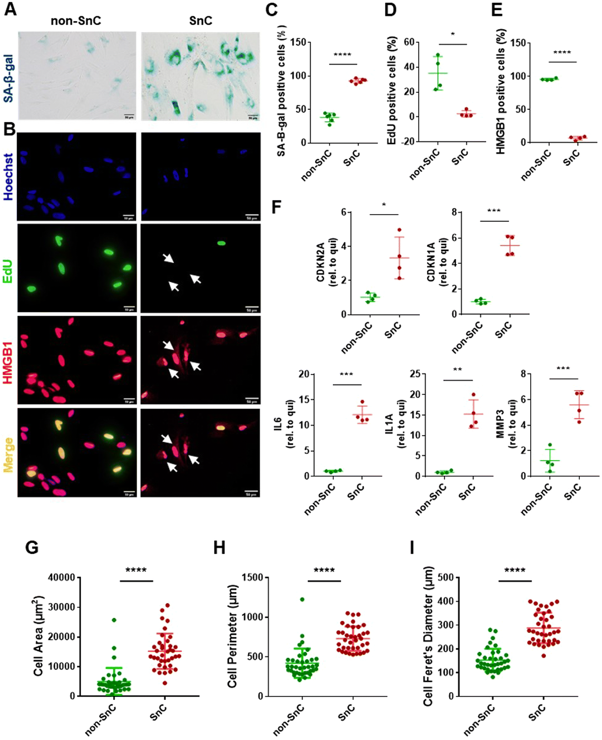 | ||
| Fig. 1 Development and validation of an in vitro senescence model. (A) Representative SA-β-gal staining and (B) immunofluorescence staining of Hoechst-labeled nuclei (blue), EdU (green, EdU-negative non-proliferating SnCs marked with arrows), and nuclear HMGB1 (red, cytoplasmic translocated HMGB1-positive SnCs marked with arrows) shown separately and as a merged image. Scale bars: 50 μm. Quantification of (C) SA-β-gal-positive (n = 6 per group), (D) EdU-positive (n = 4 per group), and (E) HMGB1-positive staining cells (n = 4 per group). (F) mRNA levels of senescence-related genes (CDKN2A and CDKN1A) and SASP factors (IL6, IL1A, and MMP3), normalized to ACTB mRNA, determined through qRT–PCR of quiescent (non-SnC) and IR-induced senescent cells (SnC) in human IMR90 lung fibroblasts. Quantification of (G) cell area (n = 37 per group), (H) cell perimeter (n = 37 per group), and (I) cell Feret's diameter (n = 37 per group). All values are mean ± S.D. *p < 0.05, **p < 0.01, ***p < 0.001, ****p < 0.0001. A two-tailed unpaired t-test was used for statistical analysis. | ||
Isolation and analysis of EVs from SnCs
After confirming senescence induction, EVs were isolated by subjecting conditioned media from the same number of non-SnC and SnC to differential ultracentrifugation (dUC). lEV (e.g., microvesicle) and sEV (e.g., exosome) pellets were reconstituted in PBS and stored at −80 °C before use (Fig. 2(A); see METHODS for details). dUC is the most widely applied method for obtaining EVs from the culture supernatant of SnCs.36 The sEVs derived from the non-SnCs and SnCs expressed classical sEV surface markers (CD9, CD63, and flotillin-1) and a biogenesis marker (TSG101), but the soluble factors did not express these markers, as verified by western blotting (Fig. 2(B)).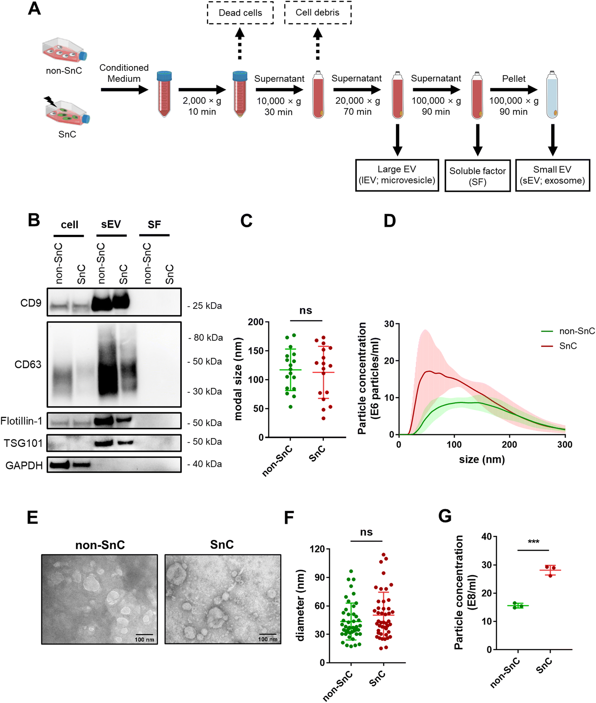 | ||
| Fig. 2 Isolation and analysis of sEVs from quiescent (non-SnCs) or senescent cells (SnCs) by differential ultracentrifugation. (A) Schematic of EV isolation workflow from the same number of non-SnC or SnC using differential ultracentrifugation. (B) Western blot analysis of cell lysate, sEVs, and soluble factors (SFs) for sEV surface markers CD9, CD63, and flotillin-1 and the sEV biogenesis marker TSG101. GAPDH was used as a loading control. (C) Nanoparticle tracking analysis (NTA) size measurements and (D) size distribution plot of sEVs derived from non-SnC and SnC (n = 17 per group). (E) Representative TEM images of sEVs. Scale bars: 100 nm. (F) Quantification of particle size from TEM images (n = 45 per group). (G) NTA particle concentration measurements of non-SnC and SnC-derived sEVs (n = 3 per group). All values are mean ± S.D. ns: not significant, ***p < 0.001. A two-tailed unpaired t-test was used for statistical analysis. | ||
To investigate changes in EV production during senescence, NTA was performed on isolated EVs from the same number of non-SnCs and SnCs. The sEVs exhibited modal sizes and size distributions corresponding to typically reported sizes (30–200 nm), which did not vary between non-SnCs and SnCs (Fig. 2(C) and (D)). TEM showed spherical sEVs of different sizes, but a negligible difference was observed in the diameters of the non-SnC- and SnC-derived sEVs (approximately 30–120 nm) (Fig. 2(E) and (F)). Consistent with previous data from human prostate cancer cells and diploid fibroblasts,37 the secretion of sEVs increased considerably in SnCs, as demonstrated by their concentrations (17 e8 mL−1 for non-SnC-derived sEVs and 30 e8 mL−1 for SnC-derived sEVs) (Fig. 2(G)). Through the activation of p53, a well-known late senescence marker, this increase can be partially mediated during a given senescence trigger by the increased expression of genes involved in endosome control and production.38,39 However, no significant differences in the concentrations of lEVs were observed in non-SnCs and SnCs (Fig. S1, ESI†).
We also employed size exclusion chromatography (SEC) as an additional purification method for the sEVs. NTA analysis of fractions 1–3, which were enriched in sEVs according to the manufacturer's instructions, indicated that the rise in sEV secretion that occurred after senescence induction (shown in Fig. 2(G)) was maintained following this separation technique (Fig. S2, ESI†). Based on these results, the isolated vesicles could be considered SnC-derived sEVs.
Mapping of nanomechanical properties of SnC-derived sEVs via PF-QNM
The morphological and nanomechanical fingerprints of non-SnC- and SnC-derived sEVs isolated by dUC were investigated using PF-QNM under liquid conditions. The PF-QNM technique adopted DMT model-based measurement.40 Specifically, in the DMT theory, the adhesion and Young's modulus were calculated from the withdrawal force curve and not the approach force curve. For this reason, the contact area where the adhesion and DMT modulus were measured could be extremely small (i.e., <5 nm in lateral resolution), making it suitable for sEV studies.41,42 Various nanomechanical properties of sEVs, such as height, DMT modulus, deformation, and adhesion, were simultaneously mapped with optimal PF-QNM conditions (Fig. S3; ESI† see METHODS for details).There was no significant difference in size between the SnC- and non-SnC-derived sEVs (Fig. 3(A)), corroborating the NTA size measurements of the sEVs (30–200 nm in diameter) confirmed by tapping-mode AFM (Fig. S3A, ESI†). Interestingly, unlike the topographic data, the DMT modulus map showed an increase in the stiffness of SnC-derived sEVs (21.90 ± 9.77 MPa) compared with non-SnC-derived sEVs (16.10 ± 7.05 MPa) (Fig. 3(B) and Table 1). Furthermore, the deformation map demonstrated that SnC-derived sEVs underwent a considerably larger deformation (4.10 ± 1.24 nm) than sEVs derived from non-SnCs (1.17 ± 0.49 nm) (Fig. 3(C)). Because the inside of the sEV is liquid, the presence of a softer core implies that the viscosity of the liquid decreases due to a lowered molecular density. Indeed, it was revealed that the amount of genetic and protein material inside SnC-derived sEVs was attenuated by a factor of 2.2 times (DNA), 2.4 times (RNA), and 2.1 times (protein) compared to that inside non-SnC-derived sEVs (Fig. S4, ESI†).
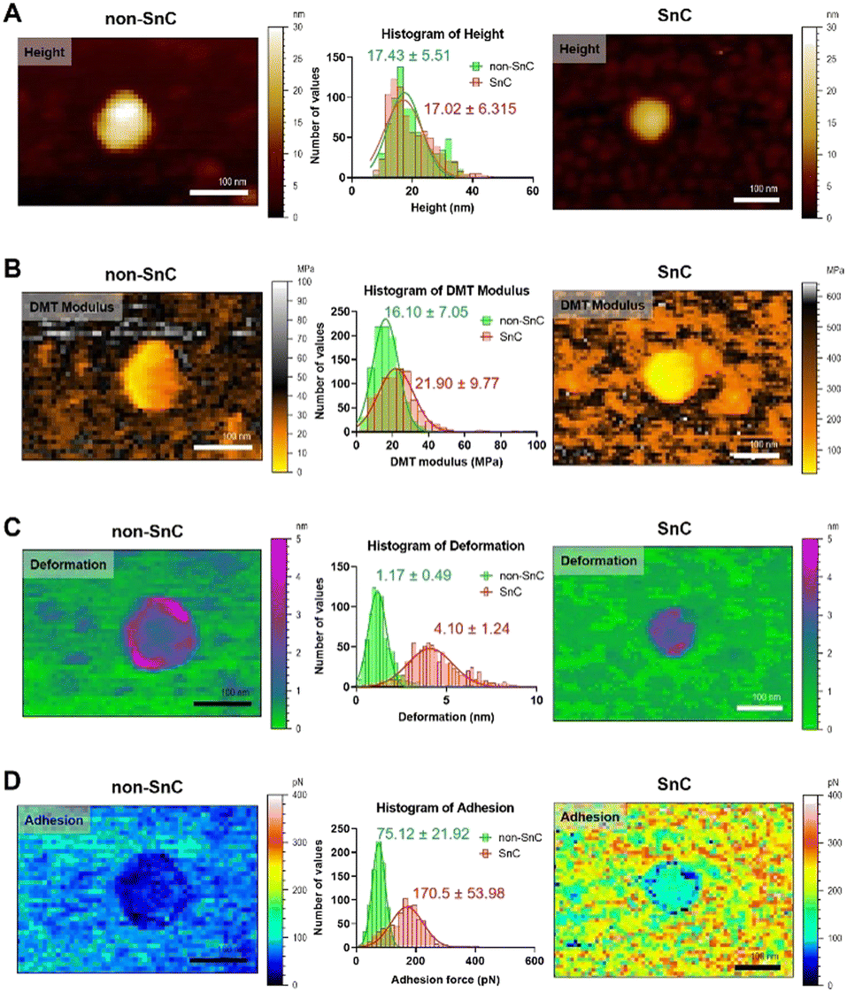 | ||
| Fig. 3 Biophysical properties obtained using PF-QNM for sEVs from non-SnC (left) and SnC (right). (A) Topographical AFM images, (B) DMT modulus (stiffness), (C) deformation, and (D) adhesion. All images are cropped. For each property, the distribution histogram is shown in the center for both types of anodes (n = 800 per group, Fig. S5 and S6, ESI†). The data were fitted to a Gaussian model, and the mean and standard deviation of the best-fit values were calculated. When comparing the sEVs of non-SnCs (green) and SnCs (red) for each parameter, (A) only the height (17.43 ± 5.51 nm (green) and 17.02 ± 6.32 nm (red)) was almost similar. The other three biophysical properties showed significant differences: (B) 16.10 ± 7.05 MPa (green) and 21.90 ± 9.77 MPa (red) for the DMT modulus, (C) 1.17 ± 0.49 nm (green) and 4.10 ± 1.24 nm (red) for deformation, and (D) 75.12 ± 21.92 pN (green) and 170.5 ± 53.98 pN (red) for adhesion. | ||
The deformation-DMT modulus plot shows that both non-SnC- and SnC-derived sEVs follow the common Young's modulus definition (Fig. S5, ESI†). For both types of sEV, an inversely proportional relationship exists between the DMT modulus and deformation, where the harder the sample is, the less deformable it is.21 However, there is little overlap between the two groups (non-SnC- and SnC-derived sEVs), implicating that there are changes in the structure and composition of the SnC-derived sEVs.43 In addition, a higher DMT modulus of SnC-derived sEVs would translate to changes in the composition of the vesicle surface, the adsorption of SASP molecules, or both. The cause of these changes in the biophysical properties of sEVs may be found in the process of cellular senescence.
Similarly, the adhesion map exhibits that the surface chemistry of SnC-derived sEVs and non-SnC-derived sEVs are different (Fig. 3(D)). In particular, the non-SnC-derived sEVs showed a small adhesion value (75.12 ± 21.92 pN) to the negatively charged AFM silicon probe, indicating that the adhesion properties were negligible because these values were equivalent to the hydrogen-bond forces.44 In contrast, the adhesion of the SnC-derived sEVs to the AFM tip had a larger mean value with wide variation (170.5 ± 53.98 pN), implying that the attractive forces increased. These values corresponded to ionic interaction forces.44 This may be associated with the aforementioned changes in DMT modulus of the SnC-derived sEVs (Fig. S6, ESI†).
Mapping of the nanoelectrical properties of SnC-derived sEVs by KPFM
To study further the compositional alterations on the surfaces of SnC-derived sEVs, we harnessed KPFM, which is an AFM application technique for mapping the local contact potential differences between a tip and a sample with subnanometer resolution.24 KPFM, also known as surface potential microscopy, is a technology that can simultaneously map height and surface potential values for sEVs (Fig. S7; ESI† see METHODS). There was no significant difference in the sizes of sEVs obtained through KPFM between non-SnC-derived sEVs (8.0 ± 2.7 nm) and SnC-derived sEVs (8.1 ± 2.8 nm) (Fig. 4(A) and (B)), and this trend was consistent with that of the PF-QNM results (Fig. 3(A)). It was noted that, owing to sample drying, the apparent size of the sEVs was smaller when imaged in ambient air (for KPFM) than when imaged under liquid conditions (for PF-QNM).22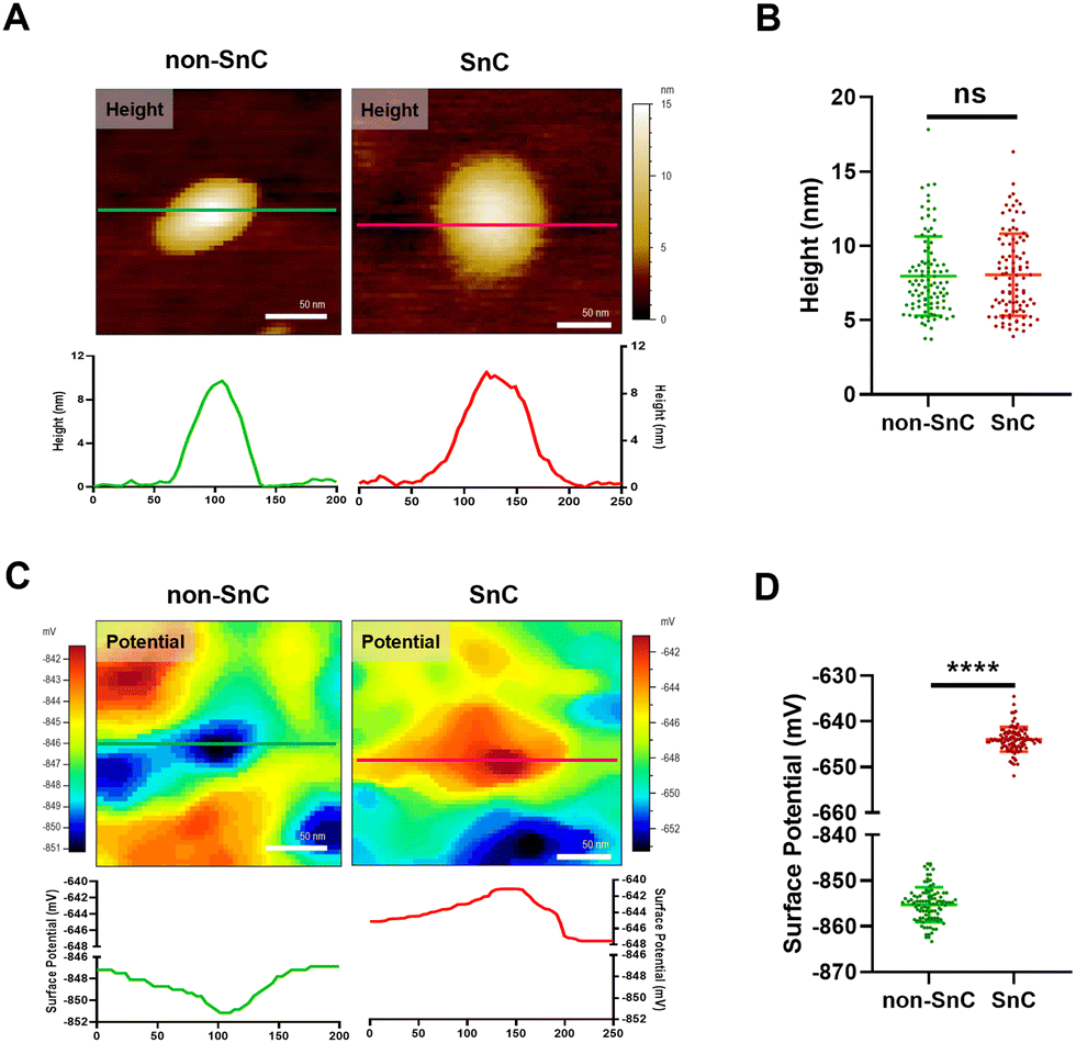 | ||
| Fig. 4 Analysis of KPFM for physical and electrical properties of sEVs isolated from non-SnCs and SnCs. (A) Topographical AFM images of a single non-SnC-derived sEVs and SnC-derived sEVs. Line profiles of each image are depicted below. (B) Quantification of the height of sEVs derived from non-SnCs and SnCs (n = 100 per group). (C) Electrical property mapping of a single non-SnC-derived sEV and SnC-derived sEVs. Line profiles of each image are shown below. (D) Quantification of the surface potential of sEVs from non-SnCs and SnCs (n = 100 per group). ns: not significant, ****p < 0.0001. A two-tailed unpaired t-test was used for statistical analysis. | ||
In contrast with the height distribution of the sEVs, a significant difference in the surface potential was observed by KPFM between non-SnC-derived sEVs (−855.2 ± 3.8 mV) and SnC-derived sEVs (−643.9 ± 2.7 mV) (Fig. 4(C) and (D)). A similar tendency was found in the verification of the surface potential with zeta potential measurement (−10.78 ± 0.47 mV for non-SnC-derived sEVs and −7.61 ± 0.18 mV for SnC-derived sEVs) (Fig. S8, ESI†). These results suggest that cellular senescence altered the membrane composition of sEVs secreted by cells. This interpretation is consistent with the literature demonstrating that the surface potential of sEVs is associated to changes in their composition of the sEV membrane.45
Biochemical features of SnC-derived sEVs using Raman spectroscopy
To understand plausible causes of different nanomechanical and biophysical traits between non-SnC- and SnC-derived sEVs, we performed Raman spectroscopy analysis which allows to characterize biological contents of sEVs in bulk according to their light scattering properties. A database of sEVs’ Raman spectra was produced by collecting and significantly enhancing their Raman signals using a plasmonic nanostructure called silver nanoforest (SNF) substrate (Fig. S9, ESI†).46 The cell-cultured media was used as a control because the media has only a negligible level of the Raman intensities compared to those of the non-SnC- and SnC-derived sEVs (Fig. S10, ESI†).A total of one hundred Raman spectra were acquired from the non-SnC- and SnC-derived sEVs, showing striking variability between them (Fig. 5(A)). With the one hundred Raman spectra, 3-dimensional principal component analysis (3D-PCA) and dimension reduction techniques were then performed to identify distinct Raman features that distinguish non-SnC- and SnC-derived sEVs and to graph the differences in variance between these two groups (Fig. 5(B)). Variance levels of the first 3 components (PC1, PC2, and PC3) were 69.4%, 13.2%, and 1.8%, respectively. There was a difference in PC3 between non-SnC- and SnC-derived sEVs although all clusters existed within the same quadrant (Fig. 5(B)), suggesting a distinct biochemical profile of the sEVs secreted by non-SnCs and SnCs based on their Raman spectra. Among the multiple different peaks observed from 600 to 2000 cm−1 in Fig. 5(A), 14 distinct peaks were further analyzed because the peaks indicated Raman spectra of functional chemical groups within biological samples (Table S1, ESI†). With the 14 peaks, using the first 10 PC scores for sEVs, a hierarchical clustering analysis was performed (Fig. S11; ESI† see METHODS for details). The analysis revealed that 872, 1,142, 1,322, 1,522, and 1,609 cm−1 of Raman spectrum were significantly different between non-SnC- and SnC-derived sEV. Noted that the other 9 peaks were subtle or negligible compared to the aforementioned 5 peaks.
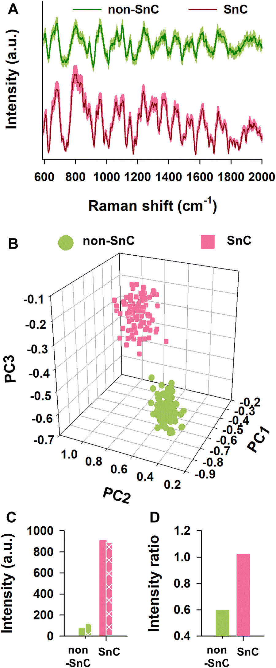 | ||
| Fig. 5 Analysis of SnC-derived sEVs using Raman spectroscopy. (A) Raman spectra (solid lines) and ±5% standard deviation (shaded area) of sEVs from non-SnC and SnC. (B) A plot of 3D-PCA scores with the first, second, and third principal components (PCs) for individual Raman spectra. (C) Raman intensities of characteristic peaks for (+) and (−) charged amino acids. Non-patterned and patterned bar plots represent the summation of the Raman intensities at characteristic peaks of (+) and (−) charged amino acids, respectively. (D) Raman intensity ratios of (+) and (−) charged amino acids, using each value of summation of Raman intensities at the characteristic peaks for (+) and (−) charged amino acids. | ||
It is well-known that amino acids can be classified according to the polarity of their residues. Thus, these significantly changed Raman peaks between non-SnC- and SnC-derived sEVs (i.e., 872, 1,142, 1,322, 1,522, and 1,609 cm−1) were further analyzed by focusing on their corresponding amino acids with a (+) or (−) net charge. The (+) charged amino acids included arginine, histidine, and lysine, and the (−) charged amino acids included aspartic acid and glutamic acid. The characteristic Raman peaks related to amine or carboxyl groups that affect polarity were also analyzed. The summation of the intensities of (+) charged amino acids at the characteristic peaks in the sEVs secreted from SnCs was bigger than those secreted from non-SnCs (Fig. 5(C)). To better distinguish the charge difference between the non-SnC- and SnC-derived sEVs, the ratio of the summation of intensities at the characteristic peaks for the (+) charged to the (−) charged amino acids was also calculated (Fig. 5(D)). This ratio was higher for the sEVs secreted from SnCs than for the sEVs secreted from non-SnCs (approximately 1.15 and 0.6, respectively).
From these results, we concluded that many positively charged substances were distributed on the surfaces of the SnC-derived sEVs, corroborating the AFM results shown in Fig. 4. As a result of independent confirmation through three different analytical methods (i.e., KPFM, zeta potential, and Raman), the differences in the surface charges of the sEVs was clearly established. Interestingly, unlike the sEVs, the lEVs showed similar summations of intensities of (+) charged and (−) charged amino acids at the characteristic peaks (Fig. S12, ESI†). These results suggest that these distinct biochemical properties measured by Raman spectroscopy, including more positively charged amino acids in SnC-derived sEVs compared to their counterparts, make sEVs good biomarkers (better than lEVs) for cellular senescence and potentially for senescence-related diseases.
Analysis of a select group of positively charged SASP proteins in SnC-derived sEVs
To gain further insight into the identities of the cargo proteins contributing to the transition of the surface potential of sEVs, we calculated the isoelectric point (pI value) of the proteins enriched in the SnC-derived sEVs. We determined their net charge at pH 7.4, which is the pH of the sEV resuspension solution (PBS), by reanalyzing published proteomic sEV data for irradiated senescent fibroblasts (Table S2, ESI†).7 We then selected three positively charged proteins, IGFBP7, gremlin-1, and annexin II, which are related to senescence growth arrest,47 senescence-related proinflammation,48 and are key exosomal SASPs associated with aging and related inflammatory diseases.49We performed bulk (western blotting) and single sEV (staining of their protein cargos by capturing the sEVs) analyses to verify whether these three senescence-associated proteins were upregulated in SnC-derived sEVs. The western blot analysis revealed that levels of IGFBP7, gremlin-1, and annexin II increased markedly in SnC-derived sEVs compared to non-SnC-derived sEVs (Fig. 6(A)). However, the bulk analysis did not permit a conclusive determination of whether all or only some SnC-derived sEV subsets carried IGFBP7, gremlin-1, and annexin II. To address this question, capture platforms of sEVs derived from non-SnCs and SnCs were developed and their protein cargos were stained on APTES-coated silicon wafers to visualize individual non-SnC- and SnC-derived sEVs, using a modification of a protocol that was previously used for single-EV imaging50,51 and by analyzing co-localization with the three senescence-associated proteins (Fig. 6(B)). We found that the total number of IGFBP7- and annexin II-carrying CD63+ vesicles tended to increase, but the difference was not significant in gremlin-1-carrying CD63+ vesicles in the sEVs of SnCs compared to those in the sEVs of non-SnCs (Fig. 6(C)–(H)). However, we cannot exclude the possibility that gremlin-1 is carried in other subsets of SnC-derived sEVs, such as CD9+ vesicles.
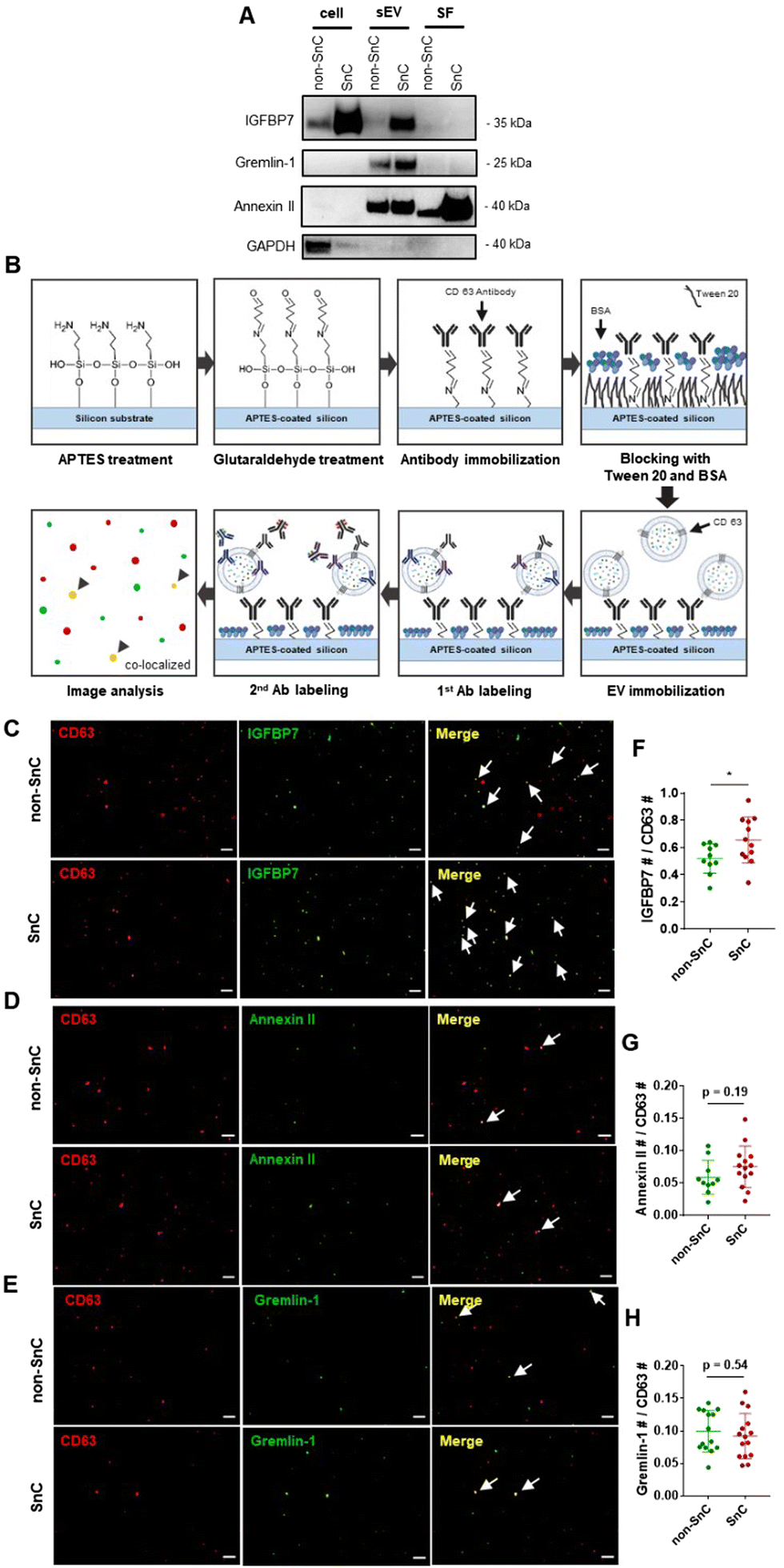 | ||
| Fig. 6 Analysis of a select group of positively charged proteins enriched in SnC-derived sEV. (A) Western blot analysis of cell lysate, sEV, and SFs for IGFBP7, gremlin-1, and annexin II. GAPDH was used as a loading control. (B) Procedure for the capture of sEV derived from non-SnCs and SnCs, staining of their SASP protein cargo on APTES-coated silicon wafer, and co-localization analysis. Immunofluorescence staining of CD63 (red, sEV marker) and (C) IGFBP7 (green, cargo protein of sEV), (D) annexin II (green, cargo protein of sEV) or (E) gremlin-1 (green, cargo protein of sEV) shown separately or as a merged image. In the merged image, arrows indicate double-positive sEVs. Scale bar: 10 μm. (F)–(H) Quantification of co-stained CD63-positive (n > 10 images per group) and cargo protein-positive sEV (n > 10 images per group). All values are mean ± S.D. ns: not significant, *p < 0.05. A two-tailed unpaired t-test was used for statistical analysis. | ||
These results suggest that three positively charged proteins—IGFBP7, gremlin-1, and annexin II—enriched in SnC-derived sEVs may be SASP protein factors contributing to their distinct biophysical and biochemical characteristics at the nanoscale (e.g., their less negative surface potential along with positively charged amino acids measured by combined AFM–Raman spectroscopy). Furthermore, these positively charged SASP proteins that increased during senescence could increase the normal cell uptake of SnC-derived sEVs and the effective transmission of the senescence phenotype.52
Conclusion
We demonstrated that combined AFM-based quantitative nanomechanical techniques and surface potential microscopy with Raman spectroscopy can be used for the high-resolution and multi-parameter characterization of SnC-derived sEVs. Without specific biomarkers for SnCs and their secreted sEVs, our method can be used to investigate the biophysical features of SnC-derived sEVs. We validated that the AFM-Raman combined system is an essential tool for identifying subtle differences in the biophysical properties of SnC- and non-SnC-derived sEVs (i.e., a slightly stiffer surface, attributed to more positively charged molecules and SASP proteins attached to the sEV surface, but a softer core owing to low levels of sEV components). Specifically, a less negative surface charge and highly deformable properties could enhance the normal cell uptake of SnC-derived sEVs and the effective transfer of the senescence phenotype.53–55 Our results suggest that these biophysical properties of sEVs can be a hallmark of cellular senescence and can be applied to develop noninvasive, safe, and sensitive analytical methods to scrutinize SnC-derived sEVs in cell culture, as well as in clinical samples such as plasma from patients with age-related diseases.Methods
Cell culture
IMR90 human fetal lung fibroblasts (CCL-186; ATCC, USA) were grown in Dulbecco's modified Eagle's medium (DMEM; Corning, USA) with 10% heat-inactivated fetal bovine serum (FBS; Gibco, USA) and 1% penicillin-streptomycin (Gibco, USA) (complete medium). All cells were maintained at 37 °C in 10% CO2/3% O2, routinely tested for mycoplasma (MycoAlert; Lonza, Switzerland), and found to be free of contamination.Senescence induction
IMR90 cells were seeded at 1.4 × 10⁴ cells per cm2 in 175 cm2 flasks and incubated at 37 °C in complete medium. One day after seeding, the cells were exposed to 20 Gy X-rays (Xstrahl RS320; Xstrahl Ltd, UK). Irradiation-induced SnCs were cultured in complete medium for 10 days to allow the development of a fully senescent phenotype. Quiescent control cells were cultured in 0.2% serum medium (quiescent medium) for 3 days. To prepare conditioned media, non-SnCs and SnCs were switched to DMEM with 10% exosome-depleted FBS (Gibco, USA) for 3 days.Senescence-associated beta-galactosidase (SA-β-gal) assay
The SA-β-gal assay was performed using a commercial kit (Cell Signaling Technology, USA) according to the manufacturer's protocol. Senescent or quiescent cells were fixed with 1X fixative solution at room temperature for 20 min, washed three times with phosphate-buffered saline (PBS), and incubated in β-gal staining solution overnight at 37 °C in the absence of CO2. SA-β-gal-positive cells were observed under an inverted microscope (EVOS M5000; Invitrogen, USA), and the percentage of positive cells in six random fields was calculated.qRT-PCR
Total RNA was extracted using the Direct-zol RNA Miniprep Kit (Zymo Research, USA) and quantified using NanoDrop ND-2000C (Thermo Scientific, USA). cDNA was synthesized using a High-Capacity cDNA Reverse Transcription Kit (Applied Biosystems, USA), according to the manufacturer's instructions. Relative mRNA levels were analyzed using the Quantstudio 3 Real-Time PCR system (Applied Biosystems, USA) with Power SYBR Green PCR Master Mix (Applied Biosystems) and calculated using the ΔΔCt method. The β-actin gene was used as the housekeeping control. The sequences of the primers were as follows: ACTB: 5′-GCT CCT CCT GAG CGC AAG TAC-3′,3′-GGA CTC GTC ATA CTC CTG CTT GC-5′; CDKN2A: 5′-CCA ACG CAC CGA ATA GTT ACG-3′,3′-GCG CTG CCC ATC ATC ATG-5′; CDKN1A: 5′-TGT CCG TCA GAA CCC ATG C-3′,3′-AAA GTC GAA GTT CCA TCG CTC-5′; interleukin 6 (IL6): 5′-CCC CTG ACC CAA CCA CAA AT-3′,3′-ATT TGC CGA AGA GCC CTC AG-5′; IL1A: 5′-GGT TGA GTT TAA GCC AAT CCA-3′,3′-TGC TGA CCT AGG CTT GAT GA-5′; and matrix metalloproteinase 3 (MMP3): 5′-CAC TCA CAG ACC TGA CTC GG-3′, 3′-GAG TCA GGG GGA GGT CCA TA-5′.Immunofluorescence
For 5-ethynyl-2′-deoxyuridine (EdU) labeling, cells in 8-well chamber slides (Nunc, Thermo Scientific, USA) were incubated for 24 h in either complete or quiescent medium containing 10 μM EdU. The cells were then fixed in 10% formalin (Biosesang, Korea), permeabilized in 0.5% Triton X-100 (Biosesang, Korea) for 20 min, and washed with 3% bovine serum albumin (BSA; Biosesang, Korea) in PBS. The permeabilized cells were subjected to the EdU reaction using the Click-iT EdU Imaging Kit (Invitrogen, USA). For co-staining with high mobility group box 1 protein (HMGB1), the cells were incubated with primary antibodies against HMGB1 (1:1000, #ab18256; Abcam, USA) overnight at 4 °C, rinsed with PBS for 3 × 5 min, and incubated with goat anti-rabbit IgG (H&L) conjugated with Alexa Fluor 594 (1:1000, #A11012, Invitrogen, USA) for 2 h at room temperature. Nuclei were counterstained with Hoechst (1:2000, #C10337; Invitrogen, USA) for 30 min at room temperature. After three final washes with PBS, the cells were mounted with aqueous mounting medium (Sigma-Aldrich, USA). Images were acquired using a fluorescence microscope (Olympus BX53; Olympus, Japan).Cell morphology analysis
The cell area, perimeter, and Feret's diameter were analyzed using ImageJ software (NIH; National Institute of Health, USA). Phase-contrast images of 37 cells per group were used to manually draw the cell boundaries.EV isolation: (1) differential ultracentrifugation
Conditioned media were collected and centrifuged at 2000 × g for 10 min at 4 °C to remove cellular debris, apoptotic bodies, and dead cells. The supernatant was transferred to 30 mL polypropylene tubes (Beckman Coulter, USA) and ultracentrifuged at 10![[thin space (1/6-em)]](https://www.rsc.org/images/entities/char_2009.gif) 000 × g for 30 min at 4 °C (Optima L-100xp 70Ti rotor; Beckman Coulter, USA). The supernatant was then transferred to new polypropylene tubes and ultracentrifuged at 20000 × g for 70 min at 4 °C to pellet the lEVs. The supernatant was transferred to new polypropylene tubes and ultracentrifuged at 100000 × g for 90 min at 4 °C to pellet the sEVs. The supernatant containing soluble factors was collected, and the pellet that corresponded to the sEVs was washed with PBS at 100000 × g for 90 min at 4 °C. Finally, the sEV pellet was resuspended in 200 μL PBS, filtered through a 0.22 μm sterile filter, and stored at −80 °C.
000 × g for 30 min at 4 °C (Optima L-100xp 70Ti rotor; Beckman Coulter, USA). The supernatant was then transferred to new polypropylene tubes and ultracentrifuged at 20000 × g for 70 min at 4 °C to pellet the lEVs. The supernatant was transferred to new polypropylene tubes and ultracentrifuged at 100000 × g for 90 min at 4 °C to pellet the sEVs. The supernatant containing soluble factors was collected, and the pellet that corresponded to the sEVs was washed with PBS at 100000 × g for 90 min at 4 °C. Finally, the sEV pellet was resuspended in 200 μL PBS, filtered through a 0.22 μm sterile filter, and stored at −80 °C.
EV isolation: (2) size exclusion chromatography (SEC)
The conditioned media were filtered using a 0.22 μm syringe filter and concentrated using Pierce 10 K MWCO centrifugal filters (Pierce, Thermo Scientific, USA) to a volume of less than 500 μL. This was loaded onto qEV original SEC columns (Izon Science, New Zealand). Thirteen sequential fractions of 500 μL were collected from the qEV Automatic Fractions Collector (Izon Science, New Zealand) according to the manufacturer's instructions. The fractions were analyzed using a nanoparticle tracking analysis (NTA) and BCA assay.Nanoparticle tracking analysis (NTA)
The particle concentration and size distribution were measured by NTA using a NanoSight LM10 instrument (Malvern Panalytical, UK). EV samples were diluted in 0.22 μm sterile-filtered PBS to achieve a concentration within the 108–109 particles per mL range for optimal NTA analysis. The analysis was carried out with NTA 2.3 software using 60 s of video captured per sample in triplicate. The camera level was set at 13–14. The detection threshold was set at 6.Transmission electron microscopy (TEM)
Formvar-carbon-coated copper grids (300 mesh; Electron Microscopy Sciences, USA) were placed on top of 30 μL droplets of the sEV samples for 5 min. The grids were transferred to 5% uranyl acetate (Electron Microscopy Sciences, USA), incubated for 5 min for negative staining, and washed with deionized water twice. The excess solution was then dried with filter paper. The grids were air-dried before imaging and examined under a transmission electron microscope (H-7650; Hitachi, Japan).PeakForce quantitative nanomechanics (PF-QNM)
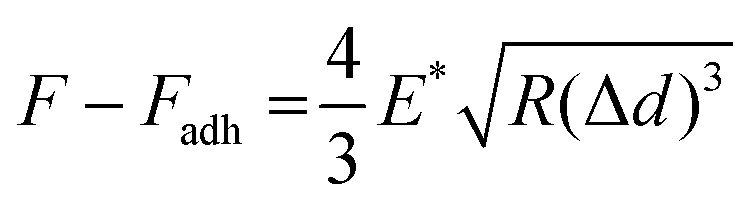
To prepare 3-aminopropyltriethoxysilane (APTES)-functionalized mica, 60 μL of APTES was deposited on freshly cleaved mica (TED PELLA, USA), incubated for 30 s, rinsed thoroughly with distilled water, and gently dried with N2 gas.21 The 60 μL of sEV solution, which was isolated from about 60 million non-SnCs and SnCs, was deposited on the APTES-functionalized mica, left for 2 h, rinsed twice with PBS to eliminate non-deposited and weakly attached sEVs, and immediately analyzed in PBS with AFM.56,57 The PF-QNM mode of a MultiMode VIII atomic force microscope (Bruker, USA) was used for the mechanical, morphological, and topological analyses of the sEVs. The PF-QNM measurements were carried out in the peak-force-tapping mode under liquid conditions.22 For more precise and consistent measurements, the AFM probes (ScanAsyst-fluid, triangular shape, 0.7 N m−1; Bruker, USA) were calibrated on the sapphire and polystyrene standards of the calibration kit (Bruker, USA). When scanning the samples, the sEVs were scanned in PBS solution with a peak force setpoint of 850pN, peak force-frequency of 2kHz, amplitude of 100nm, scan rate of 0.5Hz, and scan size of 4 μm × 4 μm. The images of the PF-QNM were recorded at 512 × 512 pixels at a frequency of 1 Hz. With three biological repeats, 80 sEVs were imaged for the mechanical characterization of each non-SnC-derived sEV and SnC-derived sEV. All AFM images were processed line by line, leveled, and analyzed using MountainsSPIP software (version 9; Digital Surf, France). During PF-QNM scanning, images were acquired from multiple channels simultaneously, including the height, Derjaguin–Muller–Toporov (DMT) modulus, adhesion, and deformation.
To obtain Young's modulus, the retract curve was fitted using the DMT model:58
All QNM parameters, such as the height, DMT modulus, deformation, and adhesion, were obtained from the cross-sectional data of the sEVs. To exclude any mechanical contributions by the nearby hard mica, only the central region of each sEV position was considered.21,42
Kelvin probe force microscopy (KPFM)
For the piranha cleaning of the silicon wafers (ePAK International, USA), a 100 mL beaker was rinsed thoroughly with distilled water. Hydrogen peroxide (H2O2) was blended with concentrated sulfuric acid (H2SO4) at a ratio of 3:1 in the beaker. The silicon wafers were immersed in piranha solution for 15 min, washed with distilled water, and dried with N2 gas (Sejong Industrial Gas Co., Korea). Chemical functionalization of the piranha-cleaned silicon substrates with APTES (Sigma-Aldrich, USA) was performed via gas-phase deposition in a desiccator.59 The processing time for functionalization was 1 h. Next, 40 μL of the sEV sample solution was dropped onto an APTES-functionalized silicon wafer for 20 min. The sample was rinsed with 100 μL of PBS and distilled water sequentially then gently dried with N2 gas. The sEVs were examined electrically, morphologically, and topologically using the amplitude modulated KPFM mode of a MultiMode VIII atomic force microscope (Bruker, USA). KPFM measurements were carried out in the lift scan mode based on the tapping mode at 23 °C and under ambient conditions. To measure the nanoelectrical properties of the sEVs, conductive AFM tips coated with Pt (SCM-PIT-V2; Bruker, USA) were used. In the first scan, a topological AFM image was acquired in the tapping mode with a zero-tip bias. In the interleave scan, the AFM tip was lifted 10 nm above the sample surface with an applied sample bias voltage to measure the surface potentials. During the interleave scan, the mechanical drive to the cantilever was disabled, and an alternating current (AC) bias voltage (VAC = 3000 mV) was applied to the probe at the mechanical resonance (ω) of the cantilever. The VAC causes the cantilever to oscillate owing to attractive and repulsive electrostatic interactions (Fes) between the probe and sample.where VDC is the direct current (DC) bias voltage and VCPD is the contact potential difference between the probe and sample.
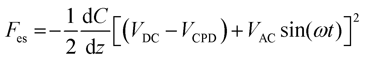
A proportional–integral–derivative feedback loop monitors and controls the amplitude of cantilever oscillations by applying a compensating VDC to the probe to cancel the probe–sample electrostatic forces (i.e., Fes). These depend on the probe–sample capacitance C and height z.25 When scanning the samples, the amplitude setpoint was 10 nm, the scan rate was 0.6Hz, and the scan size was 4 μm × 4 μm. KPFM images were recorded at 512 × 512 pixels. With three biological repeats, 100 sEVs were imaged for the surface potential characterization of each non-SnC-sEV and SnC-sEV. All AFM images were processed line by line, leveled, and analyzed using MountainsSPIP software (version 9; Digital Surf, France).
Zeta potential measurements
The zeta potential was measured three times at 25 °C according to the measurement parameters of the Particle Size Analyzer ELSZ-1000 software (Otsuka Electronics, Japan).Fabrication of silver nanoforest (SNF) substrate
SNF substrate was purchased from Kwang-Lim Precise Manufacturing (SERSpace™). A sputtering system was used to prepare nanoporous metal structures, and 6 inch wafers were used to fabricate the SNF substrate.46 The size of the entrance and the gases (He and Ar) (Seoul Specialty Gases Co., Korea) introduced into the sputtering system determined the pressure inside. The length and aperture diameter of the sputtering system were 50 mm and 4 mm, respectively. The SNF substrate was fabricated under the following conditions: a DC power of 250 W; sputtering pressure of 380 mTorr; and cluster source temperature of 15 °C. The gas flow rates were set to 84 sccm and 14 sccm for Ar and He, respectively. Finally, the SNF substrate was diced to a size of 4 × 4 mm2.Surface-enhanced Raman scattering (SERS) signal measurements
The 10 μL samples of lEVs and sEVs, which were isolated from roughly 10 million cells, were dropped onto the SNF substrate and dried in an incubator at 20 °C for 3 h. The SERS signals were acquired using 785 nm laser excitation with a Raman microscope (NS-200; Nanoscope Systems, Daejeon, Korea). The laser power was measured just above the sample state and set to 100 mW. The integration time was fixed at 0.2 s. For the measurements of SERS signals from samples on the SNF substrate, spectra were collected from at least 100 different spots for each sample. All the experiments were conducted under the same conditions (e.g., laser power and integration time). After obtaining the Raman signal, baseline correction was performed; the process was as follows with some modifications from previously published papers.60 The Raman spectra were imported into MATLAB and processed using custom-made analysis scripts. Cosmic spikes were removed from the data based on peak amplitude and a threshold on the second derivate. A spectral response correction was applied based on the measurement of a relative intensity correction sample for 785 nm excitation. Minimum and maximum post-thresholds were conducted, if applicable, by manual threshold decisions to remove background solution spectra or spectra of clearly non-single particle origin (e.g., aggregates). A primary background subtraction was performed by subtraction of 95% intensity of the averaged spectra of PBS, and the data was cropped to the fingerprint region of interest, followed by a Whittaker baseline subtraction. Smoothing of the spectra was conducted by applying the first-order Savitzky–Golay smoothing filter with a frame size of 7, and normalization of the data was applied where applicable by division by the area under the curve.PCA of SERS signals
PCA was performed by evaluating the Raman intensities over 3201 discrete wavenumbers. This was done after normalizing all the spectra for lEVs or sEVs using the built-in MATLAB function princomp. Following principal component (PC) decomposition, the first 10 PC scores for each sEV were subjected to hierarchical clustering analysis using Ward's method to create linkages based on Euclidean pairwise distances. The analysis was performed using the linkage function in MATLAB. The score plots were reported for the first three PCs, which accounted for more than 98% of the variance, and were used to analyze the Raman spectra.BCA assay
EV protein concentrations were determined using a BCA protein assay kit (Pierce, Thermo Scientific, USA) according to the manufacturer's instructions. The absorbance of the samples was read at 562 nm using a SpectraMax i3x multi-mode microplate reader (Molecular Devices, USA).Western blotting
Cells were lysed in RIPA buffer (Pierce, Thermo Scientific, USA) supplemented with 1% protease cocktail inhibitor (GenDEPOT, USA). Total protein concentration was determined using a BCA assay kit (Pierce, Thermo Scientific, USA). Equal amounts of protein from cell lysates, sEV samples, and soluble factors were resuspended in 4X Bolt LDS sample buffer (Invitrogen, USA) and heated at 80 °C for 5 min (cell lysates), 70 °C for 10 min (targets for transmembrane proteins of sEV), and 95 °C for 5 min (targets for internal proteins of sEV). Samples were separated using Bolt 4–12% Bis-Tris Mini Protein Gel (Invitrogen, USA) and transferred onto polyvinylidene difluoride (PVDF) membranes. The membranes were blocked with 5% BSA or skim milk in tris-buffered saline with Tween® 20 detergent (TBST) (Thermo Scientific, USA) for 1 h at room temperature. The primary antibodies were diluted in blocking solution and incubated with the membranes overnight at 4 °C. The primary antibodies and concentrations used were anti-CD9 (1:1000, #GTX76185; GeneTex, USA), anti-CD63 (1:1000, #LS-C204227; LSBio, USA), anti-flotillin-1 (1:1000, #18634; Cell Signaling Technology, USA), anti-TSG101 (1:1000, #ab125011; Abcam, USA), anti-GAPDH (1:1000, #sc-47724; Santa Cruz Biotechnology, USA), anti-insulin-like growth factor binding protein 7 (IGFBP7) (1:250, #sc-365293; Santa Cruz Biotechnology, USA), anti-gremlin-1 (1:250, #sc-515877; Santa Cruz Biotechnology, USA), and anti-annexin II (1:500, #sc-28385; Santa Cruz Biotechnology, USA). The membranes were washed in TBST three times for 5 min each and incubated with HRP-conjugated secondary anti-mouse (for CD9, GAPDH, IGFBP7, gremlin-1, and annexin II) (1:10000, #7076; Cell Signaling Technology, USA), anti-rabbit (for flotillin-1 and TSG101) (1:10000, #7074; Cell Signaling Technology, USA), and anti-goat (for CD63) (1:10000, Santa Cruz, USA) antibodies for 1 h at room temperature. Band detection was performed using the SuperSignal West Pico PLUS ECL reagent (Thermo Scientific, USA) in a ChemiDoc Touch Imaging System (Bio-Rad, USA). Band intensity was quantified using Image Lab (Bio-Rad, USA).
Immunoassays of sEV cargo
APTES-coated silicon wafers (1 cm × 1 cm) were washed with PBS and immersed in 2.5% (v/v) glutaraldehyde (Sigma-Aldrich, USA) in PBS for 30 min at room temperature. This was done to generate aldehyde groups using a glutaraldehyde linker.61 The wafers were then washed thoroughly with PBS to avoid non-specific antibody absorption. To covalently bind sEVs-specific antibodies to the wafers and make an antibody layer, the glutaraldehyde-activated wafers were reacted with 0.1 mg mL−1 of CD63 (#LS-C204227; LSBio, USA) capture antibodies in PBS for 30 min and 1% Tween 20 (Sigma-Aldrich, USA) at room temperature for 15 min. Subsequently, 2 mg mL−1 BSA (Biosesang, Korea) in PBS was added for 30 min to block the surface. To immobilize the sEVs on the wafers, sEV samples were added, incubated for 15 min, washed with PBS, fixed with 10% formalin (Biosesang, Korea) for 10 min, and permeabilized using 0.1% (v/v) Triton X-100 (Biosesang, Korea) in PBS for 5 min at room temperature. Detecting the sEVs and their cargo proteins was then achieved by incubating the wafers with primary antibodies for 90 min: anti-CD63 (1:100, #LS-C204227; LSBio, USA), anti-IGFBP7 (1:100, #sc-365293; Santa Cruz Biotechnology, USA), anti-gremlin-1 (1:100, #sc-515877; Santa Cruz Biotechnology, USA), and anti-annexin II (1:100, #sc-28385; Santa Cruz Biotechnology, USA). After washing with PBS, the wafers were incubated with donkey anti-goat IgG (H&L) conjugated with Alexa Fluor 594 (for CD63) (1:500, #A-11058; Invitrogen, USA) and donkey anti-mouse IgG (H&L) conjugated with Alexa Fluor 488 (for IGFBP7, gremlin-1, and annexin II) (1:500, #A-21202; Invitrogen, USA) for 30 min. The wafers were then mounted with an aqueous mounting medium (Sigma-Aldrich, USA). Imaging was performed using a fluorescence microscope (Olympus BX53; Olympus, Japan).Statistical analyses
Statistical analyses were performed using the GraphPad Prism 7 software (GraphPad Software, USA). Unpaired Student's t-tests were used to compare the means of the two groups, unless otherwise specified. P-values represented the following: ns, not significant; *p < 0.05, **p < 0.01, ***p < 0.001, and ****p < 0.0001. Error bars represented the standard deviation of ≥3 independent experiments, unless otherwise stated.Author contributions
H. G. L. and S. R. designed the experiments, analyzed the data, and wrote the manuscript. S. R. and G. L. conducted the AFM, PF-QNM, and KPFM analyses. H. J. K. and Y. H. performed the Raman spectroscopy experiments. S. K. integrated the studies and reviewed & edited the manuscript. O. H. J., G. L., and Y. H. conceived the idea, planned and directed the studies, and wrote the manuscript. O. H. J. oversaw the project. All authors checked the manuscript.Conflicts of interest
There are no conflicts to declare.Acknowledgements
This study was supported by a Korea University Grant K2011311 (O. H. J.), and National Research Foundation of Korea Grants 2020R1C1C1009921 (O. H. J.), 2020R1A2C2102262 (G. L.), and 2021R1C1C1012822 (Y. H.), and Korea Institute of Machinery & Materials NK239E (Y. H.). The authors are thankful to Hyunwook Kim at Korea University College of Medicine for helping in the acquisition of TEM images.References
- J. Campisi, Annu. Rev. Physiol., 2013, 75, 685–705 CrossRef CAS PubMed.
- D. J. Baker, B. G. Childs, M. Durik, M. E. Wijers, C. J. Sieben, J. Zhong, R. A. Saltness, K. B. Jeganathan, G. C. Verzosa, A. Pezeshki, K. Khazaie, J. D. Miller and J. M. van Deursen, Nature, 2016, 530, 184–189 CrossRef CAS PubMed.
- O. H. Jeon, C. Kim, R. M. Laberge, M. Demaria, S. Rathod, A. P. Vasserot, J. W. Chung, D. H. Kim, Y. Poon, N. David, D. J. Baker, J. M. van Deursen, J. Campisi and J. H. Elisseeff, Nat. Med., 2017, 23, 775–781 CrossRef CAS PubMed.
- J. C. Acosta, A. Banito, T. Wuestefeld, A. Georgilis, P. Janich, J. P. Morton, D. Athineos, T. W. Kang, F. Lasitschka, M. Andrulis, G. Pascual, K. J. Morris, S. Khan, H. Jin, G. Dharmalingam, A. P. Snijders, T. Carroll, D. Capper, C. Pritchard, G. J. Inman, T. Longerich, O. J. Sansom, S. A. Benitah, L. Zender and J. Gil, Nat. Cell Biol., 2013, 15, 978–990 CrossRef CAS PubMed.
- J. P. Coppe, C. K. Patil, F. Rodier, Y. Sun, D. P. Munoz, J. Goldstein, P. S. Nelson, P. Y. Desprez and J. Campisi, PLoS Biol., 2008, 6, 2853–2868 CrossRef CAS PubMed.
- O. H. Jeon, M. Mehdipour, T. H. Gil, M. H. Kang, N. W. Aguirre, Z. R. Robinson, C. Kato, J. Etienne, H. G. Lee, F. Alimirah, V. Walavalkar, P. Y. Desprez, M. J. Conboy, J. Campisi and I. M. Conboy, Nat. Metab., 2022, 4, 995–1006 CrossRef CAS PubMed.
- N. Basisty, A. Kale, O. H. Jeon, C. Kuehnemann, T. Payne, C. Rao, A. Holtz, S. Shah, V. Sharma, L. Ferrucci, J. Campisi and B. Schilling, PLoS Biol., 2020, 18, e3000599 CrossRef PubMed.
- O. H. Jeon, D. R. Wilson, C. C. Clement, S. Rathod, C. Cherry, B. Powell, Z. Lee, A. M. Khalil, J. J. Green, J. Campisi, L. Santambrogio, K. W. Witwer and J. H. Elisseeff, JCI Insight, 2019, 4, e125019 CrossRef PubMed.
- F. J. Alibhai, F. Lim, A. Yeganeh, P. V. DiStefano, T. Binesh-Marvasti, A. Belfiore, L. Wlodarek, D. Gustafson, S. Millar, S. H. Li, R. D. Weisel, J. E. Fish and R. K. Li, Aging Cell, 2020, 19, e13103 CrossRef CAS.
- M. Takasugi, Aging Cell, 2018, 17, e12734 CrossRef PubMed.
- G. van Niel, G. D’Angelo and G. Raposo, Nat. Rev. Mol. Cell Biol., 2018, 19, 213–228 CrossRef CAS.
- R. Wallis, N. Josipovic, H. Mizen, A. Robles-Tenorio, E. J. Tyler, A. Papantonis and C. L. Bishop, J. Extracell. Vesicles, 2021, 10, e12041 CAS.
- S. Y. Kim, D. Khanal, P. Tharkar, B. Kalionis and W. Chrzanowski, Nanoscale Horiz., 2018, 3, 430–438 RSC.
- M. LeClaire, J. Gimzewski and S. Sharma, Nano Sel., 2021, 2, 1–15 CrossRef CAS.
- R. Kalluri and V. S. LeBleu, Science, 2020, 367, eaau6977 CrossRef CAS PubMed.
- M. Borghesan, J. Fafian-Labora, O. Eleftheriadou, P. Carpintero-Fernandez, M. Paez-Ribes, G. Vizcay-Barrena, A. Swisa, D. Kolodkin-Gal, P. Ximenez-Embun, R. Lowe, B. Martin-Martin, H. Peinado, J. Munoz, R. A. Fleck, Y. Dor, I. Ben-Porath, A. Vossenkamper, D. Munoz-Espin and A. O’Loghlen, Cell Rep., 2019, 27, 3956–3971 CrossRef CAS PubMed.
- J. A. Fafian-Labora, J. A. Rodriguez-Navarro and A. O’Loghlen, Cell Metab., 2020, 32, 71–86e75 CrossRef CAS PubMed.
- A. Sahu, Z. J. Clemens, S. N. Shinde, S. Sivakumar, A. Pius, A. Bhatia, S. Picciolini, C. Carlomagno, A. Gualerzi, M. Bedoni, B. Van Houten, M. Lovalekar, N. F. Fitz, I. Lefterov, A. Barchowsky, R. Koldamova and F. Ambrosio, Nat. Aging, 2021, 1, 1148–1161 CrossRef PubMed.
- S. Sharma, H. I. Rasool, V. Palanisamy, C. Mathisen, M. Schmidt, D. T. Wong and J. K. Gimzewski, ACS Nano, 2010, 4, 1921–1926 CrossRef CAS PubMed.
- A. Ridolfi, M. Brucale, C. Montis, L. Caselli, L. Paolini, A. Borup, A. T. Boysen, F. Loria, M. J. C. van Herwijnen, M. Kleinjan, P. Nejsum, N. Zarovni, M. H. M. Wauben, D. Berti, P. Bergese and F. Valle, Anal. Chem., 2020, 92, 10274–10282 CrossRef CAS PubMed.
- S. A. Gazze, S. J. Thomas, J. Garcia-Parra, D. W. James, P. Rees, V. Marsh-Durban, R. Corteling, D. Gonzalez, R. S. Conlan and L. W. Francis, Nanoscale, 2021, 13, 6129–6141 RSC.
- J. Hardij, F. Cecchet, A. Berquand, D. Gheldof, C. Chatelain, F. Mullier, B. Chatelain and J. M. Dogne, J. Extracell. Vesicles, 2013, 2, 21045 CrossRef PubMed.
- A. C. Dumitru, M. A. Poncin, L. Conrard, Y. F. Dufrene, D. Tyteca and D. Alsteens, Nanoscale Horiz., 2018, 3, 293–304 RSC.
- W. Melitz, J. Shen, A. C. Kummel and S. Lee, Surf. Sci. Rep., 2011, 66, 1–27 CrossRef CAS.
- J. Park, J. Yang, G. Lee, C. Y. Lee, S. Na, S. W. Lee, S. Haam, Y. M. Huh, D. S. Yoon, K. Eom and T. Kwon, ACS Nano, 2011, 5, 6981–6990 CrossRef CAS PubMed.
- G. Lee, H. Lee, K. Nam, J. H. Han, J. Yang, S. W. Lee, D. S. Yoon, K. Eom and T. Kwon, Nanoscale Res. Lett., 2012, 7, 608 CrossRef PubMed.
- G. Lee, W. Lee, H. Lee, S. Woo Lee, D. Sung Yoon, K. Eom and T. Kwon, Appl. Phys. Lett., 2012, 101, 43703 CrossRef.
- J. Carmicheal, C. Hayashi, X. Huang, L. Liu, Y. Lu, A. Krasnoslobodtsev, A. Lushnikov, P. G. Kshirsagar, A. Patel, M. Jain, Y. L. Lyubchenko, Y. Lu, S. K. Batra and S. Kaur, Nanomedicine, 2019, 16, 88–96 CrossRef CAS PubMed.
- G. P. Dimri, X. Lee, G. Basile, M. Acosta, G. Scott, C. Roskelley, E. E. Medrano, M. Linskens, I. Rubelj and O. Pereira-Smith, et al. , Proc. Natl. Acad. Sci. U. S. A., 1995, 92, 9363–9367 CrossRef CAS.
- A. R. Davalos, M. Kawahara, G. K. Malhotra, N. Schaum, J. Huang, U. Ved, C. M. Beausejour, J. P. Coppe, F. Rodier and J. Campisi, J. Cell Biol., 2013, 201, 613–629 CrossRef CAS.
- J. Campisi and F. d’Adda di Fagagna, Nat. Rev. Mol. Cell Biol., 2007, 8, 729–740 CrossRef CAS PubMed.
- A. Krtolica, S. Parrinello, S. Lockett, P. Y. Desprez and J. Campisi, Proc. Natl. Acad. Sci. U. S. A., 2001, 98, 12072–12077 CrossRef CAS.
- J. P. Coppe, P. Y. Desprez, A. Krtolica and J. Campisi, Annu. Rev. Pathol., 2010, 5, 99–118 CrossRef CAS.
- A. V. Orjalo, D. Bhaumik, B. K. Gengler, G. K. Scott and J. Campisi, Proc. Natl. Acad. Sci. U. S. A., 2009, 106, 17031–17036 CrossRef CAS PubMed.
- E. S. Hwang, G. Yoon and H. T. Kang, Cell. Mol. Life Sci., 2009, 66, 2503–2524 CrossRef CAS PubMed.
- C. Thery, S. Amigorena, G. Raposo and A. Clayton, Curr. Protoc. Cell Biol., 2006, ch. 3, Unit 3 22 Search PubMed.
- M. Takasugi, R. Okada, A. Takahashi, D. Virya Chen, S. Watanabe and E. Hara, Nat. Commun., 2017, 8, 15729 CrossRef CAS.
- X. Yu, T. Riley and A. J. Levine, FEBS J., 2009, 276, 2201–2212 CrossRef CAS PubMed.
- S. Buratta, L. Urbanelli, K. Sagini, S. Giovagnoli, S. Caponi, D. Fioretto, N. Mitro, D. Caruso and C. Emiliani, PLoS One, 2017, 12, e0188840 CrossRef PubMed.
- B. V. Derjaguin, V. M. Muller and Y. P. Toporov, J. Colloid Interface Sci., 1975, 53, 314–326 CrossRef CAS.
- B. Pettinger, Bruker Application note, 2012, 128.
- J. Adamcik, A. Berquand and R. Mezzenga, Appl. Phys. Lett., 2011, 98, 193701 CrossRef.
- J. Rodriguez, A. Rico, E. Otero and W. M. Rainforth, Acta Mater., 2009, 57, 3148–3156 CrossRef CAS.
- I. S. Park, T. J. Kwak, G. Lee, M. Son, J. W. Choi, S. Choi, K. Nam, S. Y. Lee, W. J. Chang, K. Eom, D. S. Yoon, S. Lee, R. Bashir and S. W. Lee, ACS Nano, 2016, 10, 4011–4019 CrossRef CAS PubMed.
- Y. Choi, S. M. Kim, Y. Heo, G. Lee, J. Y. Kang and D. S. Yoon, Nanotechnology, 2021, 32, 025705 CrossRef CAS PubMed.
- H. S. Kim, T. Lee, J. Yun, G. Lee and Y. Hong, Microchem. J., 2021, 160, 105632 CrossRef CAS.
- N. Wajapeyee, R. W. Serra, X. Zhu, M. Mahalingam and M. R. Green, Cell, 2008, 132, 363–374 CrossRef CAS PubMed.
- M. Corsini, E. Moroni, C. Ravelli, G. Andres, E. Grillo, I. H. Ali, D. P. Brazil, M. Presta and S. Mitola, Arterioscler., Thromb., Vasc. Biol., 2014, 34, 136–145 CrossRef CAS PubMed.
- A. Chretien, E. Delaive, M. Dieu, C. Demazy, N. Ninane, M. Raes and O. Toussaint, Exp. Gerontol., 2008, 43, 353–359 CrossRef CAS.
- Y. D. Chen, Y. T. Fang, Y. L. Cheng, C. F. Lin, L. J. Hsu, S. Y. Wang, R. Anderson, C. P. Chang and Y. S. Lin, Sci. Rep., 2017, 7, 5676 CrossRef PubMed.
- C. Han, H. Kang, J. Yi, M. Kang, H. Lee, Y. Kwon, J. Jung, J. Lee and J. Park, J. Extracell. Vesicles, 2021, 10, e12047 CAS.
- C. Ferro, H. F. Florindo and H. A. Santos, Adv. Healthcare Mater., 2021, 10, 2100598 CrossRef CAS.
- H. D. Summers, P. Rees, J. T. W. Wang and K. T. Al-Jamal, Nanoscale, 2017, 9, 6800–6807 RSC.
- W. Jiang, Q. Wang, X. L. Qu, L. X. Wang, X. R. Wei, D. Q. Zhu and K. Yang, Sci. Total Environ., 2017, 574, 771–780 CrossRef CAS.
- S. Sharma, K. Das, J. Woo and J. K. Gimzewski, J. R. Soc., Interface, 2014, 11, 20131150 CrossRef PubMed.
- A. Touhami, B. Nysten and Y. F. Dufrene, Langmuir, 2003, 19, 4539–4543 CrossRef CAS.
- Y. F. Dufrene, T. Ando, R. Garcia, D. Alsteens, D. Martinez-Martin, A. Engel, C. Gerber and D. J. Muller, Nat. Nanotechnol., 2017, 12, 295–307 CrossRef CAS PubMed.
- B. V. Derjaguin, V. M. Muller and Y. P. Toporov, Prog. Surf. Sci., 1994, 45, 131–143 CrossRef.
- F. Zhang, K. Sautter, A. M. Larsen, D. A. Findley, R. C. Davis, H. Samha and M. R. Linford, Langmuir, 2010, 26, 14648–14654 CrossRef CAS PubMed.
- J. Penders, A. Nagelkerke, E. M. Cunnane, S. V. Pedersen, I. J. Pence, R. C. Coombes and M. M. Stevens, ACS Nano, 2021, 15, 18192–18205 CrossRef CAS.
- N. S. K. Gunda, M. Singh, L. Norman, K. Kaur and S. K. Mitra, Appl. Surf. Sci., 2014, 305, 522–530 CrossRef CAS.
Footnotes |
| † Electronic supplementary information (ESI) available. See DOI: https://doi.org/10.1039/d2nh00220e |
| ‡ H. G. Lee and S. Roh contributed equally to this work. |
| This journal is © The Royal Society of Chemistry 2022 |