
Strong Purcell enhancement at telecom wavelengths afforded by spinel Fe3O4 nanocrystals with size-tunable plasmonic properties†
Ekaterina A.
Dolgopolova
 a,
Dongfang
Li
a,
Steven T.
Hartman
b,
John
Watt
a,
Carlos
Ríos
cd,
Juejun
Hu
e,
Ravi
Kukkadapu
f,
Joanna
Casson
g,
Riya
Bose
h,
Anton V.
Malko
h,
Anastasia V.
Blake
a,
Sergei
Ivanov
a,
Oleksiy
Roslyak
i,
Andrei
Piryatinski
j,
Han
Htoon
a,
Hou-Tong
Chen
a,
Ghanshyam
Pilania
b and
Jennifer A.
Hollingsworth
*a
a,
Dongfang
Li
a,
Steven T.
Hartman
b,
John
Watt
a,
Carlos
Ríos
cd,
Juejun
Hu
e,
Ravi
Kukkadapu
f,
Joanna
Casson
g,
Riya
Bose
h,
Anton V.
Malko
h,
Anastasia V.
Blake
a,
Sergei
Ivanov
a,
Oleksiy
Roslyak
i,
Andrei
Piryatinski
j,
Han
Htoon
a,
Hou-Tong
Chen
a,
Ghanshyam
Pilania
b and
Jennifer A.
Hollingsworth
*a
aMaterials Physics and Applications Division: Center for Integrated Nanotechnologies, Los Alamos National Laboratory, Los Alamos, NM 87545, USA. E-mail: jenn@lanl.gov
bMaterials Science & Technology Division, Los Alamos National Laboratory, Los Alamos, NM 87545, USA
cDepartment of Materials Science and Engineering, University of Maryland, College Park, MD 20742, USA
dInstitute for Research in Electronics and Applied Physics, University of Maryland, College Park, MD 20742, USA
eDepartment of Materials Science & Engineering, Massachusetts Institute of Technology, Cambridge, MA 02139, USA
fEnvironmental Molecular Sciences Laboratory, Pacific Northwest National Laboratory, Richland, WA 99354, USA
gChemistry Division, Los Alamos National Laboratory, Los Alamos, NM 87545, USA
hDepartment of Physics, The University of Texas at Dallas, Richardson, TX 75080, USA
iDepartment of Physics and Engineering Physics, Fordham University, Bronx, NY 10458, USA
jTheoretical Division, Los Alamos National Laboratory, Los Alamos, NM 87545, USA
First published on 11th December 2021
Abstract
Developments in the field of nanoplasmonics have the potential to advance applications from information processing and telecommunications to light-based sensing. Traditionally, nanoscale noble metals such as gold and silver have been used to achieve the targeted enhancements in light-matter interactions that result from the presence of localized surface plasmons (LSPs). However, interest has recently shifted to intrinsically doped semiconductor nanocrystals (NCs) for their ability to display LSP resonances (LSPRs) over a much broader spectral range, including the infrared (IR). Among semiconducting plasmonic NCs, spinel metal oxides (sp-MOs) are an emerging class of materials with distinct advantages in accessing the telecommunications bands in the IR and affording useful environmental stability. Here, we report the plasmonic properties of Fe3O4 sp-MO NCs, known previously only for their magnetic functionality, and demonstrate their ability to modify the light-emission properties of telecom-emitting quantum dots (QDs). We establish the synthetic conditions for tuning sp-MO NC size, composition and doping characteristics, resulting in unprecedented tunability of electronic behavior and plasmonic response over 450 nm. In particular, with diameter-dependent variations in free-electron concentration across the Fe3O4 NC series, we introduce a strong NC size dependency onto the optical response. In addition, our observation of plasmonics-enhanced decay rates from telecom-emitting QDs reveals Purcell enhancement factors for simple plasmonic-spacer-emitter sandwich structures up to 51-fold, which are comparable to values achieved previously only for emitters in the visible range coupled with conventional noble metal NCs.
New conceptsMagnetite Fe3O4 nanocrystals (NCs) are well-known for their utility in a myriad of biomedical applications from drug delivery to contrast agents for magnetic-resonance imaging. They are also magnetic-recording media and ferrofluids for speakers, or separating agents for treatment of heavy-metal-contaminated water. But, has a potential application space been overlooked? Are they useful as something other than a magnetic nanoparticle? We show for the first time that Fe3O4 NCs can possess another useful property—plasmonic character. This is possible because Fe3O4 is a degenerate semiconductor, and like other such semiconductors it can achieve carrier concentrations >1019 cm−3—sufficient to support a localized surface plasmon (LSP) when stimulated by light resonant with the plasmon frequency. The Fe3O4 NC LSP resonances are size-tunable over at least 1287–1738 nm, thus encompassing the technologically significant telecommunications window. Using a simple sandwich structure, we show that a layer of Fe3O4 NCs when separated by a thin dielectric spacer from a layer of PbS/CdS quantum dots (QDs) emitting in a telecom band causes a strong Purcell effect, with Purcell factors reaching ∼50. This unique demonstration of a purely material plasmonic effect in the infrared rivals results for noble-metal plasmonic-NCs paired with visible-light emitting QDs. |
Introduction
Light impinging on a metallic nanocrystal (NC) induces free electrons to oscillate collectively, creating a localized surface plasmon (LSP). The LSP causes greatly enhanced coupling between the incident light and the metal matter, which can be used in applications requiring either a significant enhancement of the intensity of the electromagnetic field, e.g., chemical sensing, or the confinement of light beyond the diffraction limit, e.g., plasmonics-augmented optical communications.1–5 Due to the high bandwidth of light, photonic circuits are an important, ultrafast alternative to nanoelectronics for information transmission. However, conventional optical components cannot be optimally miniaturized for high-density on-chip packaging without somehow circumventing the diffraction limit of light. Nanoscale plasmonic structures and materials are sought that could be coupled with photon sources to bring optical circuitry to the nanoscale. In particular, the wavelength range most useful for communicating information with light is the telecommunications window from 1260 to 1625 nm. The LSP resonances (LSPRs) of the metallic NCs do not reach this spectral window. The high and nonadjustable carrier concentrations (1022–1023 cm−3) that are characteristic of metals cause LSPRs to lie in the visible spectrum, with limited adjustment possible based on particle size and shape to ∼1200 nm.2,6Alternatives to metals have been sought to address this lack of spectral tunability, as well as other deficiencies of metals.6–9 In particular, degenerately doped semiconducting nanomaterials exhibit plasmonic character when electrons in the conduction band reach carrier concentrations >1019 cm−3. This lower carrier density compared to metals allows the LSPRs of plasmonic semiconductors to be tuned to short-wavelength infrared (SWIR; 1.4–3 μm) and even mid-wavelength infrared (MWIR; 3–8 μm) spectral ranges. Furthermore, being doping-level dependent, plasmonic behavior can be modulated through synthetic control, or even dynamically, post-synthesis, e.g., photochemically or electrochemically.7 Metal oxide, nitride and chalcogenide semiconducting nanomaterials have now been demonstrated to support true LSPRs and to do so from the visible to the MWIR.6,7,10,11
Despite these advances in nanomaterial plasmonics, the principal materials studied to date exhibit limited dopability and environmental stability. Namely, simple metal oxides, e.g., In2O3, ZnO, CdO, are not amenable to p-type doping, while Cu chalcogenides, which can be used to access p-type doping, are unstable. The oxides are n-type due to the valence band maximum being dominated by O2− 2p states, which permits only limited p-type doping as generated deep-lying holes are strongly localized on oxygen sites. P-type doping in Cu-based materials depends on Cu vacancies, where Cu is notoriously mobile, affording limited long-term stability.11
An alternative class of semiconducting metal oxides may hold the key to both dopability and stability—spinel metal oxides (sp-MOs). sp-MO systems can provide multiple doping modes for controlling free carrier density.12 Namely, the sp-MO structure possesses the general formula, A2BO4. Commonly, A3+ and B2+ cations occupy octahedrally (Oh; 1/2 occupied) and tetrahedrally (Td; 1/8 occupied) coordinated sites, respectively, in a cubic close-packed framework of O2− anions. An unusual self-doping is possible by effects of structural disorder and off-stoichiometry. The former entails the A3+ and B2+ cations swapping sites (known as antisite defect pairs), while the latter results from a change in the 2![[thin space (1/6-em)]](https://www.rsc.org/images/entities/char_2009.gif) :1:4 ratio of elements (involving crystal-structure vacancies, interstitial defects or antisites).
:1:4 ratio of elements (involving crystal-structure vacancies, interstitial defects or antisites).
Motivated by theoretical studies of intrinsically doped sp-MOs,12 as well as a demonstration by Manna and co-workers of tunable LSPRs for Ga2FeO4 sp-MO NCs,13 we investigate the potential for magnetite Fe3O4 sp-MO NCs to exhibit plasmonic behavior, where iron is present in two oxidation states—(Fe3+)2Fe2+O4. Ga2FeO4 and Fe3O4 adopt the so-called inverse spinel structure in which the octahedral sublattice is shared by equal proportions of A3+ and B2+ cations, while the tetrahedrally-coordinated sites are filled by A3+ rather than B2+ cations (Fig. 1(a)). One potential scenario for off-stoichiometry in Fe3O4 is the formation of cation vacancies on B sites, which would result in an increase in the ratio of Fe3+ to Fe2+.
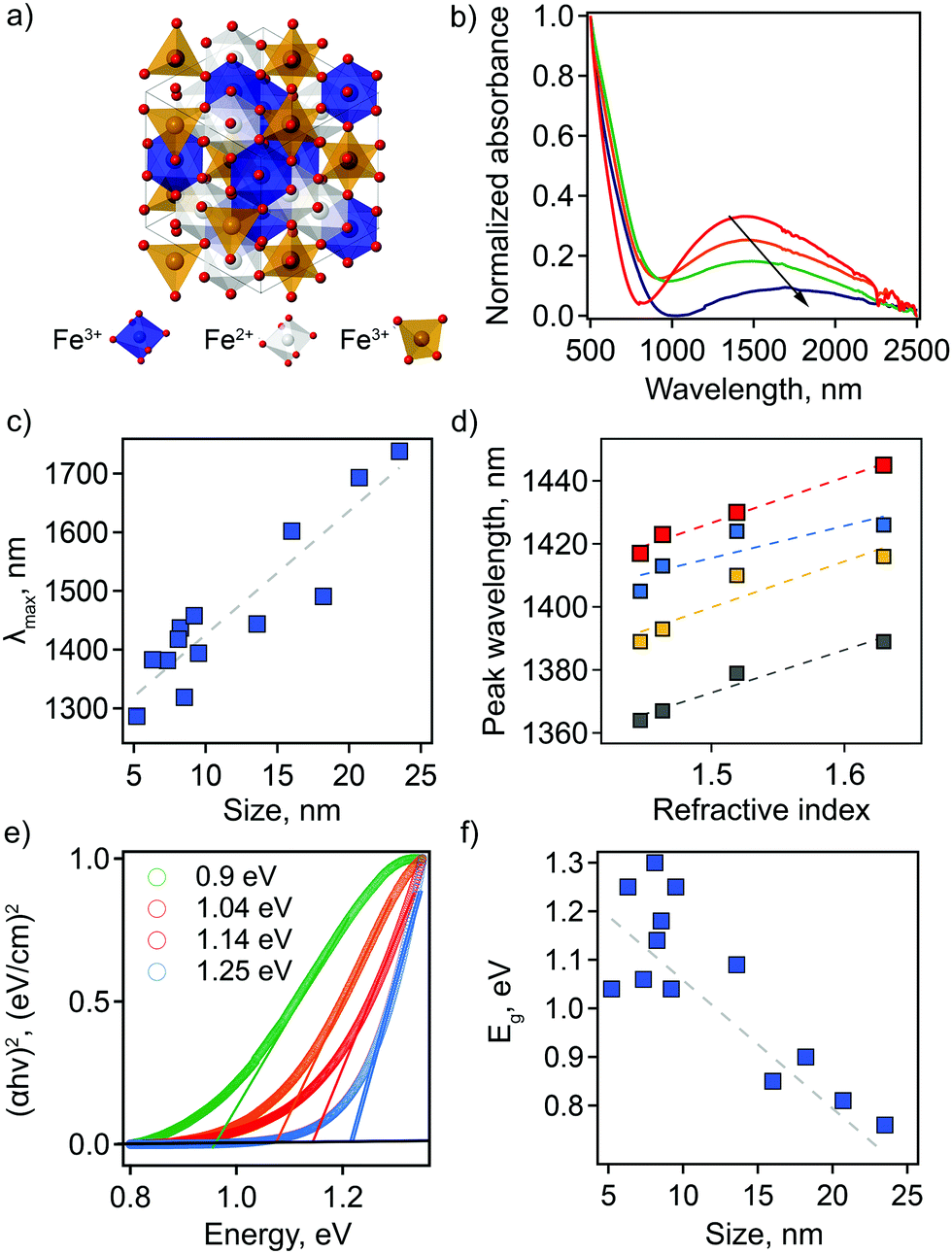 | ||
| Fig. 1 (a) A view of the inverse spinel Fe3O4 unit cell. (b) Vis-NIR absorption curves of Fe3O4 NCs dispersed in TCE. Arrow indicates changes in intensity and shape of the spectra with increasing particle size: 8.2 ± 1.6 (red), 9.2 ± 2.5 (orange), 18.2 ± 4.3 (green), and 20.7 ± 4.5 nm (navy). All spectra are normalized at 500 nm. (c) Dependence of the LSPR maximum on particle size. (d) LSPR peak wavelength plotted as a function of the solvent refractive index for Fe3O4 NCs with different particle sizes: 8.2 ± 1.6 (red), 6.3 ± 1.8 (blue), 8.5 ± 2.8 (yellow), and 7.3 ± 4.0 nm (gray). The dashed lines show linear fits. (e) Plots of (αhν)2vs. photon energy with corresponding values for optical bandgap energy, Eg, of the direct transition for Fe3O4 NCs with different particle sizes: 18.2 ± 4.3 (green), 9.2 ± 2.5 (orange), 8.2 ± 1.6 (red), and 6.3 ± 1.8 (blue). Open circles are measured data; solid lines are linear fits. (f) Eg as a function of NC size. | ||
Here, we show that chemical modification of the magnetite structure can indeed induce an LSPR, and, significantly, we demonstrate that a thin film of Fe3O4 NCs can cause a large modification to the spontaneous emission rate of coupled PbS/CdS quantum dots (QDs). Specifically, we utilize a comprehensive suite of analytical methods to structurally and optically characterize the Fe3O4 NCs to establish correlations between NC size, crystalline phase and composition and LSPR properties of peak position and width, including accounting for spontaneous formation of maghemite (γ-Fe2O3) shells on the Fe3O4 core. Theoretical modeling is performed to understand the mechanism of the LSPR response in Fe3O4 NCs and to extract carrier density as a function of synthetic parameters. Although Fe3O4 NCs are well-studied for their magnetic properties, there remains a gap in understanding pertaining to optical and electronic properties, with little insight into the impact of stoichiometry despite the important role this can play in sp-MO systems. Finally, the Fe3O4 sp-MO NCs are assembled into hybrid layered structures with infrared-emitting colloidal QDs to quantify distance-dependent Purcell enhancement, which has previously only been documented for coupled metallic NC and emitter couples active in the visible spectral range.14–18
Results and discussion
To establish correlations between optical properties and particle structure, we synthesized Fe3O4 NCs for a range of particle sizes through facile modification of synthetic parameters (see ESI† for detailed methods).13,19,20 Transmission electron microscopy (TEM) was used to characterize size and shape of the prepared nanoparticles. A population of 200 NCs was analyzed in each case to obtain a statistically representative size distribution, from which an average particle size, d, was determined (Table S1 and Fig. S1, ESI†). The obtained NC sizes vary from 5.2 ± 1.1 nm to 23.5 ± 3.6 nm depending on the choice of specific synthetic parameters (Table S1, ESI†).The LSPR has not been described previously for magnetite NCs, but is, in fact, clearly visible in absorption spectra. Its basic characteristics, as well as tunability and dependencies on NC size and solvent properties, are shown in Fig. 1. First, absorption spectra of Fe3O4 NCs dispersed in tetrachloroethylene (TCE) show an absorption peak in the NIR region with a maximum (peak) wavelength (λmax) ranging from 1287 nm (0.96 eV) to 1738 nm (0.71 eV). This corresponds to the LSPR wavelength. Both the peak position and peak shape depend on NC size (Fig. 1(b and c) and Table S1, ESI†). Specifically, the LSPR peak shifts toward higher wavelengths and becomes broader, substantially decreasing in intensity, with increasing particle diameter (Fig. 1(b and c)).
Second, the optical response of Fe3O4 NCs is also sensitive to the surrounding medium, i.e., solvent in which nanoparticles are dispersed. A redshift in λmax is observed with increasing solvent refractive index (Fig. 1(d)). This is a distinctive feature of an LSPR and has been reported for different types of plasmonic materials ranging from metals to other classes of semiconducting plasmonic materials.21,22 The Fe3O4 NCs show a sensitivity factor (SFaverage)—defined as the shift of the LSPR peak wavelength per unit change in refractive index of the surrounding medium—of 132. This value is lower than the ones previously reported for semiconducting plasmonic materials active in the NIR range: WO3−x, SF = 280; MoO3−x, SF = 260, and Cu2−xS, SF = 350.22–26 Interestingly, for Fe3O4 NCs SF increases with increasing NC size (Fig. 1(d) and Fig. S2, ESI†). The sensitivity factor for gold and silver nanoparticles is known to be dependent on geometric parameters, i.e., aspect ratio in that case,25,26 but such size and shape effects have yet to be established for semiconducting plasmonic NCs. Our results suggest that geometric considerations also play a role in the case of doped semiconductors.
The absorption onset in the visible-NIR range, which is directly related to the semiconductor optical bandgap (Eg), also depends on NC size. The value of the Eg can be estimated from the plot of (αhν)2versus photon energy hν, where α is the absorption coefficient (Fig. 1(e) and Table S1, ESI†). By extrapolation of the linear region of these plots to the zero intercept, we find that the optical band gap increases from 0.76 eV to 1.3 eV with a decrease in NC size. This absorption onset is not affected by a change in solvent refractive index (Fig. S3, ESI†), in contrast with the LSPR peak position. For semiconducting NCs, the change in optical bandgap value with changes in NC size is typically associated with the quantum confinement effect. However, for degenerately doped semiconducting NCs optical bandgap also depends on free carrier concentration. In this case, an apparent increase in bandgap values is described by the Moss–Burstein effect, such that a higher number of free electrons leads to partial filling of the conduction band. This scenario would lead to the conclusion that the observation of an increasing bandgap energy with decreasing NC size means that the smaller NCs are characterized by a higher number of free electrons. For nonstoichiometric magnetite nanoparticles, an excess of free electrons could be accounted for by a higher ratio of Fe2+:Fe3+ cations. As we show below, this is in fact the case for the smaller NCs in our study.
The electronic origins of the LSPR feature in the Fe3O4 NCs were investigated using density functional theory (DFT). Band structures of the stoichiometric and off-stoichiometric bulk Fe3O4 inverse spinel were calculated (Fig. S4–S6, ESI†). As described above, for the stoichiometric case, Td sites are occupied by Fe3+ ions while Oh sites are occupied by 50% Fe2+ and 50% Fe3+ ions ordered in a specific configuration. Off-stoichiometric Fe3O4 is simulated by adding or removing electrons from the supercell. Added extra electrons tend to either localize or delocalize on the octahedral sublattice (with the delocalized configuration slightly lower in energy, 0.10 eV per formula unit). A localization of an added electron on an Fe3+ ion leads to an additional Fe2+ ion, thereby increasing the relative ratio of Fe2+/Fe3+ ions on the octahedral sublattice compared to the stoichiometric case. In the electronic band structure, this gives rise to an additional filled electronic band at the top of the valence band near the Fermi level. On the other hand, a delocalized configuration leads to a more conventional n-type doping behavior with the Fermi energy shifted to the bottom of the conduction band. The computed electronic band structures for both off-stoichiometric cases are shown in Fig. S5 and S6 (ESI†), along with the localized and delocalized electronic charge density plots. In contrast to the electron-addition case, removal of any extra electrons from the stoichiometric supercell results in systematic removal of the electronic bands corresponding to the Fe2+ ions in the valence band edge, due to the conversion of Fe2+ to Fe3+ ions at the Oh sites. Furthermore, as a result of this oxidation-state switching, removal of electrons should not lead to a p-type doping behavior. Finally, our computations also confirm Fe vacancies on Oh sites as a particularly low formation energy point defect (see Fig. S7, ESI†). This is consistent with previous studies showing that cation vacancies play a key role in the structural transformation from magnetite to maghemite.27,28
Altogether, these results indicate that the observed LSPR response in Fe3O4 likely occurs by delocalization of the electronic charge density from the Fe2+ ions to the Oh sites. We note that this conclusion is further supported by the past spectroscopic observations reporting a gradual and complete flattening of UV-vis-NIR absorption spectra as Fe2+ ions in magnetite nanoparticles were systematically oxidized to Fe3+.29
Additionally, we employed a combination of characterization techniques to correlate the observed behavior and theoretical description of the NC plasmonic response directly with changes in structure and composition. The sp-MO crystal structure was confirmed by powder X-ray diffraction (PXRD), with all patterns exhibiting the characteristic peaks of the A2BO4 spinel structure (space group Fd![[3 with combining macron]](https://www.rsc.org/images/entities/char_0033_0304.gif) m; Fig. 2(a)). We note, however, that magnetite Fe3O4 exhibits a PXRD pattern that is very similar to maghemite γ-Fe2O3. In fact, refinement of the PXRD patterns here reveals lattice parameters that are intermediate between the two phases, i.e., lattice parameter a lies between ∼8.39 and ∼8.38, while for a purely magnetite or maghemite structure a = 8.397 or 8.330, respectively. The observed maghemite character has been explained previously for a range of NC sizes as resulting from the presence of an oxidized surface layer and, therefore, indicative of the unintentional formation of a magnetite/maghemite core/shell structure.30–32
m; Fig. 2(a)). We note, however, that magnetite Fe3O4 exhibits a PXRD pattern that is very similar to maghemite γ-Fe2O3. In fact, refinement of the PXRD patterns here reveals lattice parameters that are intermediate between the two phases, i.e., lattice parameter a lies between ∼8.39 and ∼8.38, while for a purely magnetite or maghemite structure a = 8.397 or 8.330, respectively. The observed maghemite character has been explained previously for a range of NC sizes as resulting from the presence of an oxidized surface layer and, therefore, indicative of the unintentional formation of a magnetite/maghemite core/shell structure.30–32
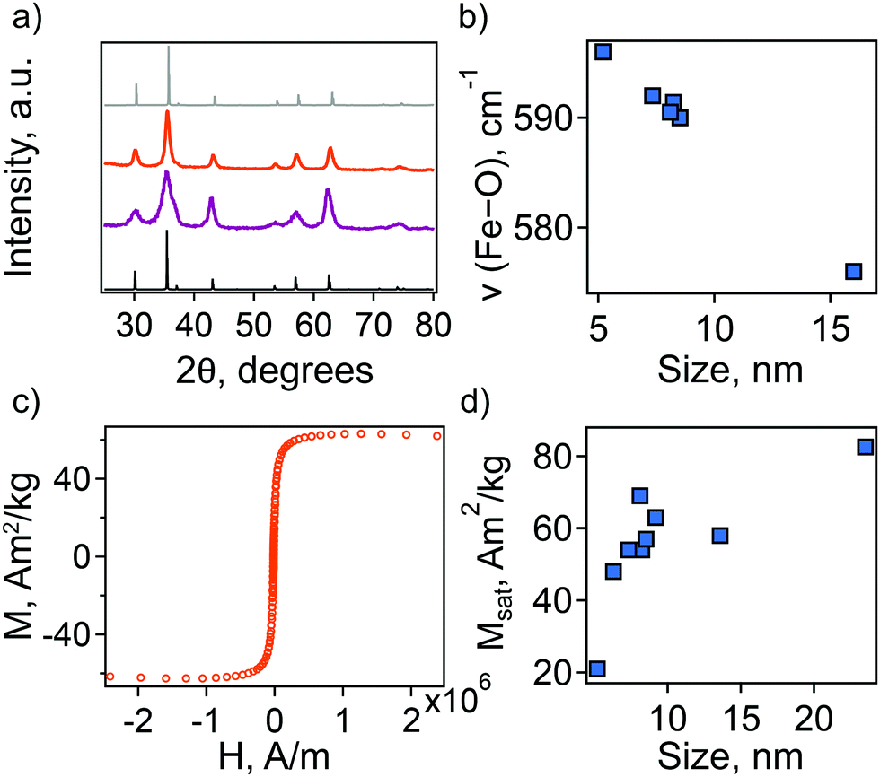 | ||
| Fig. 2 (a) XRD patterns of Fe3O4 NCs with different particle size: 5.2 ± 1.1 nm (purple) and 9.2 ± 2.5 nm (orange). Standard line patterns are shown for magnetite (JCPDS No. 19-0629, black) and maghemite (JCPDS No. 39-1346, gray). (b) Dependence of characteristic FTIR peak on particle diameter. (c) Magnetization curve measured at 50 K for 9.2 ± 2.5 nm Fe3O4 NCs. (d) Dependence of saturation magnetization, Msat, on particle size. | ||
The presence of maghemite in the NCs was also assessed using FTIR spectroscopy. The different iron oxide phases display characteristic bands corresponding to Fe–O stretching modes.32,33 In the region from 500 to 600 cm−1, a strong band at ∼570 cm−1 is a feature of magnetite, while in maghemite the band is shifted to 590 cm−1. For all the synthesized NCs the position of this band is intermediate between magnetite and maghemite. Its position shifts closer to that of stoichiometric magnetite with an increase in particle size (Fig. 2(b)).
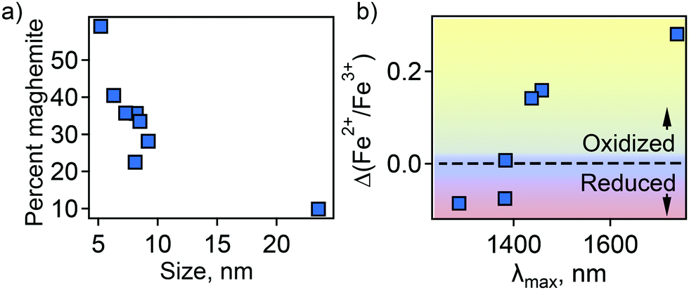
In an attempt to understand this size dependency, we further probed magnetite-maghemite character via an assessment of a magnetically disordered (dead)-layer compared to magnetite. Specifically, magnetization curves were obtained at 50 K using vibrating sample magnetometry (VSM; representative magnetization curve is shown in Fig. 2(c). This measurement is thought to provide insight into the thickness of the maghemite shell). The saturation magnetization increases with an increase in NC size from 23% of the value for bulk magnetite in the case of the small (5.2 ± 1.1 nm) NCs to 90% in the case of the very large (23.5 ± 3.6 nm) particles (Fig. 2(d)). Such an observation is frequently attributed to a disproportionate influence of the maghemite shell in the smaller NCs. Here, we calculated the thickness of the magnetically disordered shell layer, e, according to a model suggested by Chen and co-workers (see Methods section for details; Fig. S8, ESI†).34 The maghemite layer thickness was observed to vary, but was generally in the range of ∼0.5 nm (Table S2, ESI†). Based on the relationship between shell thickness and NC diameter in each case, the percentage of the total particle volume represented by maghemite was determined and found to be large for the smallest NCs (e.g., ∼60% for 5.2 nm diameter particles; Fig. 3(a)) and smaller for the largest NCs (e.g., ∼10% for NCs > 20 nm in diameter). These results are consistent with the results obtained by FTIR analysis. Additionally, considering magnetite core-size only, the LSPR peak wavelength is still linearly dependent on size (Fig. S9, ESI†), confirming that the magnetite structure is giving rise to the plasmonic properties.
 | ||
| Fig. 3 (a) Percent of total particle volume that is maghemite shell. (b) Dependence of LSPR peak position on magnetite character of the NC core—Fe2+ rich (reduced) or Fe2+ poor (oxidized). | ||
Next, the magnetite character, or stoichiometry, of the NC cores was assessed. First, two techniques were used to determine Fe2+/Fe3+ ratio in the particles as a whole—Mössbauer spectroscopy (MBS, Fig. S10, ESI†) and acidic dissolution. Mössbauer spectra were obtained at 120 and 140 K and modeled with a Voigt-based hyperfine distribution model.35,36 Fe2+/Fe3+ ratios obtained by both methods are shown in Table S2 (ESI†). Then, using the determined shell and core volume percentages (Fig. 3(a)), we calculated the ratio of Fe2+/Fe3+ that would be present in the core assuming the shell is pure maghemite and the core pure magnetite. These values were compared to the values obtained by MBS or acidic dissolution. An interesting size trend was observed. Namely, relative to a pure magnetite Fe2+/Fe3+ ratio of 0.5, the smallest NCs are Fe2+ rich, while the largest NCs are Fe2+ poor (Table S2, ESI†). Furthermore, the LSPR peak position follows the trend in core Fe2+/Fe3+ ratio—red-shifting with decreasing Fe2+ content (Fig. 3(b)).
This observation confirms our prediction based on theoretical modeling that a decrease in Fe2+ concentration causes changes in the dispersive conduction band—shift of the Fermi energy to the bottom of the conduction band—that dampens the plasmonic response. Taken together, this supports the idea of a carrier density-dependent plasmonic response for Fe3O4 NCs if the higher number of Fe2+ ions are also associated with a higher number of free electrons, and may also explain the observed increase in optical bandgap with decreasing particle size.
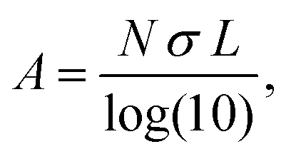
To more explicitly connect the observed NIR response with free carrier concentration, we determined carrier concentration as a function of Fe2+/Fe3+ stoichiometry using a combination of Mie scattering theory and the Drude model. Such an approach has previously been used to explain experimental LSPR absorption spectra of Ga- and Fe-rich Ga2FeO4 spinel NCs.13 Within the quasi-static approximation of Mie theory, the absorption of the NC solution is described using the Lambert–Beer law as
with R, c and ω representing the NC radius, speed of light in vacuum and optical frequency, respectively. Following the Drude model, the frequency dependent dielectric function of the material εp(ω) can be described by
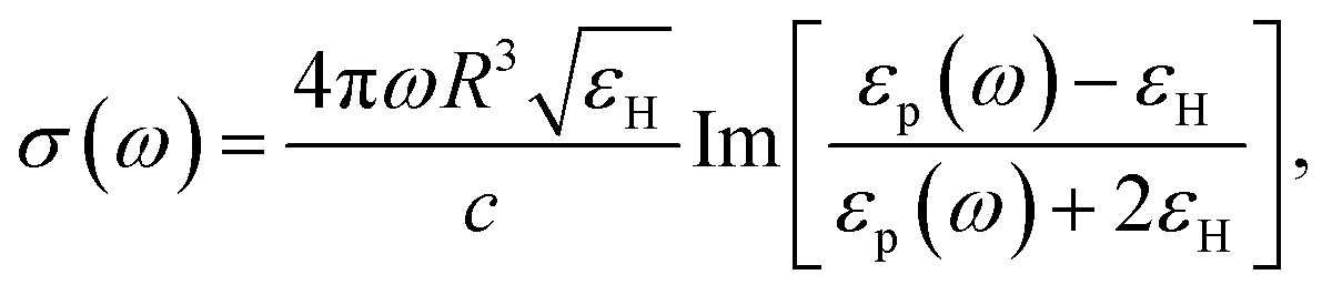
where ε∞ is the high frequency electronic contribution to the total dielectric function, γ is the free carrier damping constant, and
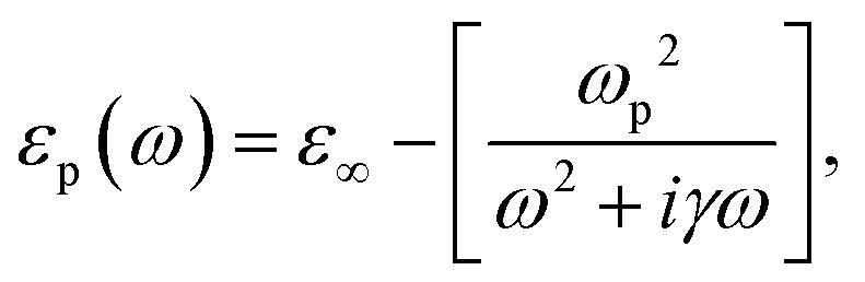
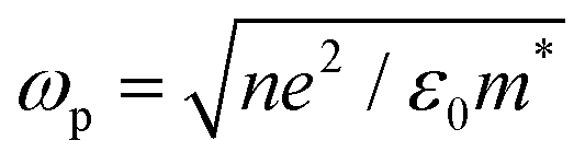 is the plasma frequency, with n, e, ε0 and m* being carrier density, electron charge, vacuum dielectric permittivity and charge carrier effective mass, respectively. ε∞ and m* were extracted from the DFT calculations. The dependence of the two most important parameters, namely the charge density n and the damping constant γ, on the absorption profiles is depicted in Fig. 4(a) and (b), respectively. Here, it is evident that a lower charge density leads to a broader absorption peak with the peak position shifted to larger wavelengths, while an increased damping constant manifests as a decreased peak height at a fixed wavelength. Fig. 4(c) showcases the fitting profiles as a function of the experimentally determined Fe2+/Fe3+ stoichiometry of several different NCs. In each case, the calculated concentration of free charge carriers is found to be on the order of 1022 cm−3, which is well within the range of those typically found in degenerately doped semiconductors.37 More importantly, our fits confirm a correlation between the Fe2+/Fe3+ ratio and the charge carrier density, with a higher charge carrier density observed in the case of a higher Fe2+ content in the core.
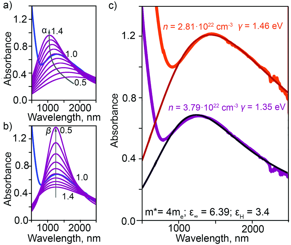 | ||
| Fig. 4 Parametric dependence of (a) charge density n (n = α × 3.79×1022 cm−3) and (b) damping constant γ (γ = β × 1.35 eV) on the fitted LSPR absorption profiles for NCs with Fe2+/Fe3+ ratio in excess compared to stoichiometric magnetite (NCs with 4.5 nm core). (c) Experimentally-measured and fitted LSPR absorption profiles obtained by employing the Mie theory and the Drude model for NCs with different core magnetite character: from relatively reduced (purple; 5.2 nm core) to relatively oxidized (red; 9.2 nm core). Charge density, n, and damping constant, γ, are shown for each. | ||
As discussed above, the development of alternative plasmonic materials with LSPRs in the infrared could be potentially useful for the enhancement of light emission from quantum emitters that photoluminescence at telecommunication wavelengths. Lead chalcogenide QDs are emitters capable of producing photoluminescence (PL) at these wavelengths, but they suffer from non-optimal light-emission properties. Namely, while it is possible to synthesize these QDs with high quantum yields (QYs), lead chalcogenide QDs are invariably characterized by long radiative lifetimes (order of a microsecond). This translates to slow photon cycling from excitation to emission and back to excitation again, resulting in low brightness at the single-QD level compared, e.g., to visible-light-emitting CdSe QDs for which emission decays in only nanoseconds.38 Also, detectors at this wavelength range are not optimized for single-photon detection. Access to plasmonic NCs with telecom LSPRs could help address these issues by enhancing the rate of the radiative decay of excitation. Emission enhancement in the visible spectral range has been demonstrated for QDs paired with metallic plasmonic NCs, e.g., Au and Ag. For example, Ag NCs were prepared as a layer on a solid substrate to which a polymer spacer was added prior to deposition of a thin layer of CdSe QDs.14 The spacer layer is used to limit non-radiative energy or charge transfer from quantum emitters to plasmonic nanocrystals.39 In this case, an enhancement factor of 24 was determined for an optimal spacer thickness of 5 nm. For similar systems, enhancement ranged from 2.7 to 24.14–18
Here, we replace metal NCs with Fe3O4 NCs and CdSe QDs with PbS/CdS QDs (Fig. 5(a)). For optimal coupling, we use QDs whose PL wavelength overlaps with the sp-MO LSPR (Fig. 5(b)). The distance between QDs and NPs was precisely tuned by changing the thickness of the spacer layer from 2.5 to 20 nm. Rather than a polymer spacer that can have inconsistent thickness after deposition and can influence QD lifetime due to the passivation of surface defects (Fig. S11, ESI†),40,41 we selected two different types of amorphous chalcogenide materials—Ge23Sb7S70 (GSS) and Ge2Sb2Se4Te (GSST)—and aluminum oxide (AlOx) as spacer layers. These materials were chosen because they are deposited with precision via single-source thermal evaporation (GSS/GSST)42,43 or atomic layer deposition (AlOx)44–47 near or at room temperature, respectively, which avoids damage to the sp-MO NC layer. Importantly, plasmonic properties of the Fe3O4 NCs were preserved in their thin-film form with only a slight shift in the plasmonic response toward a longer wavelength due to the change in average dielectric constant in the medium surrounding the NCs (from solution to air to chalcogenide; Fig. S12, ESI†). Furthermore, amorphous chalcogenides are characterized by tunable broadband transparency in the IR (Fig. S13 and S14, ESI†).
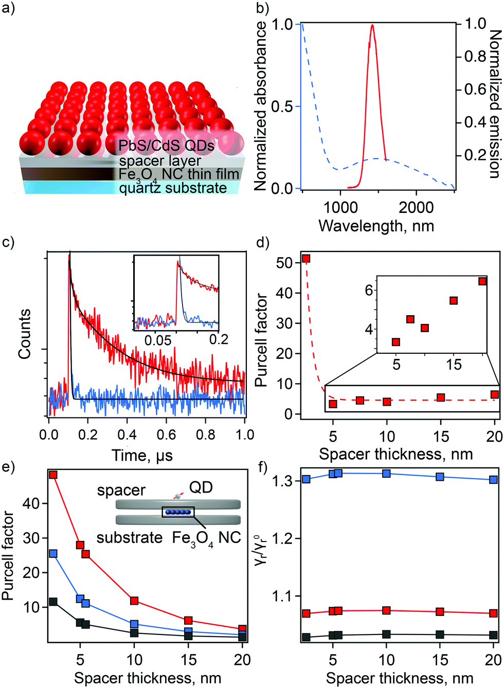 | ||
| Fig. 5 (a) A schematic representation of Fe3O4 thin film coated with spacer layer and PbS/CdS deposited on the surface. (b) The normalized absorption spectrum of Fe3O4 suspended in TCE (blue dashed line) and emission spectrum of NIR-PbS/CdS QDs (solid red line). (c) Fluorescence decays of QDs on a 2.5 nm GSS layer (red) and coupled to Fe3O4 NC thin film separated by 2.5 nm GSS layer (blue). Black solid lines are fits of decay. (d) The Purcell factor as a function of spacer thickness for GSS spacer material. (Dashed line is a guide to the eye). (e) Calculated Purcell factor (ratio of total decay rates) for an array of Fe3O4 NCs between two disks as shown in the inset with different spacers GSS (red), GSST (blue), and Al2O3 (gray). (f) Calculated ratio of the radiative decay rates for the same system with and without Fe3O4 NC layer for GSS (red), GSST (blue), and Al2O3 (gray). | ||
Time-resolved PL (tr-PL) spectroscopy was employed to quantify the enhancement in spontaneous decay of the QDs, i.e., plasmonic Purcell effect. PL lifetimes for QDs on the spacer material with and without an underlying layer of Fe3O4 NCs were compared for the full range of spacer-layer thicknesses. PL decay curves show a spacer-thickness-dependent enhancement of the PL decay rate for QDs in the presence of Fe3O4 NCs for all used spacer materials (Fig. S15, ESI†). The maximum shortening of average lifetime values was observed at spacer thicknesses of 2.5 and 7.5 nm for chalcogenide material (GSS and GSST) and AlOx spacers, respectively. In particular, decay curves for QDs applied to a 2.5 nm thick GSS spacer with and without the underlying sp-MO NC layer are shown in Fig. 5(c). In this case, the calculated Purcell enhancement factor, defined as the ratio of the PL decay times in the absence and presence of the Fe3O4 NC layer (FP = τspacer-quartz/τspacer-on-NPs) was 51 (Fig. 5(d)).48 Biexponential fitting was applied in all cases, with FP values determined using the average τ (see ESI† for fitting details). Notably, the observed maximum enhancement is >2 times that previously reported for plasmonic NC/spacer/QD systems active in the visible range.14 Expectedly, with a subsequent increase in spacer thickness, the Purcell factor is reduced (Fig. 5(d)).
We have performed simulations of the Purcell effect associated with the Fe3O4 NCs. As illustrated in the inset to Fig. 5(e), a cluster of 5 × 5 spherical plasmonic NCs, each 10 nm in diameter, forming a square lattice with the period of 11 nm is placed between two dielectric disks, each 282 nm in diameter. The top disks of varying thickness (to 20 nm) and the bottom with constant thickness (20 nm) simulate the spacer material and the quartz substrate, respectively. A transition dipole is placed 4.2 nm above the top disk, which is the radius of the PbS/CdS QDs used in the experiment. Using the boundary element method implemented into the MNPBEM computational toolbox,49 we performed simulations of the dipole total and radiative decay rates in the presence of Fe3O4 NCs and in the absence of an Fe3O4 NC layer. In the simulations, the plasmonic NC response was parameterized using the Drude model for Fe2+/Fe3+ = 0.20.
The calculated dependance of the Purcell enhancement factor on the spacer thickness is shown in Fig. 5(e). Comparing the calculation results with experiment (Fig. 5(d) and Fig. S15, ESI†), we see a reasonable, order-of-magnitude agreement. The calculations clearly show that the GSS spacer facilitates the best performance, and this is also observed in the experiment. The discrepancies between calculations and experiment, e.g., experimentally observed faster decay of the Purcell factor with the spacer thickness, can be attributed to the idealizations of the adopted model. Specifically, the model does not account for the variation of the plasmonic NC sizes and random arrangement of the nanoparticles within the layers affecting Purcell factor scaling with spacer thickness.
The plasmonic Purcell factor describes enhancement of the QD spontaneous decay rate contributed by both radiative and nonradiative channels.50 Experimental determination of the radiative rate enhancement is a challenging task. Therefore, we further employ our simulations to gain an insight into this quantity. The ratio of the radiative decay rates with and without Fe3O4 NCs is shown in Fig. 5(f). Depending on the spacer material, the radiative decay rate enhancement ranges between 2% and 30%. Thus, according to this calculation, a major contribution to the Purcell factor comes from non-radiative energy transfer to plasmonic NCs and its subsequent dissipation due to the Ohmic losses. Such a behavior is expected due to the small size of the Fe3O4 NCs and close proximity of the QDs to this layer. However, it is anticipated that synthesis of larger Fe3O4 NCs (e.g., up to ∼100 nm in diameter) could facilitate fabrication of plasmonic nano-antennas with much higher radiative rate enhancement than is possible in the current thin-film platform.51–54
Conclusions
The plasmonic properties for a novel class of plasmonic nanomaterial—Fe3O4 sp-MOs—have been elucidated. Specifically, we showed that magnetite NCs can exhibit LSPRs in the NIR, including important telecommunications bands. Synthetic modifications, such as use of different solvents and surfactants, afford control over NC size and, thereby, enable fine-tuning of the plasmonic response. In agreement with previous reports, we confirmed that unintentional oxidation of Fe3O4 NCs results in the formation of an oxidized maghemite shell on top of the magnetite core. Here, we further combined structural characterization and theoretical modeling to show that NC core size is directly correlated with parameters that influence LSPR peak position, i.e., change in Fe2+/Fe3+ ratio. In this way, key gaps in understanding of magnetite plasmonic and electronic properties were addressed. Finally, we showed that it is possible to elicit strong plasmonic enhancement of the Purcell factor for IR-emitting QDs. This result points the way to an important next step—reaching comparable radiative rate enhancements by taking advantage of nano-antenna structures, as has been shown for emitters in the visible range.53 In addition to the favorable plasmonic behavior, we find that the LSPR characteristics are maintained over months in solvent-suspension without any precautions taken with respect to storage conditions, and in the solid state, a thin layer of the explored chalcogenide spacer material prevented any shifting in LSPR peak position of fully air-exposed Fe3O4 sp-MO NC monolayer films. Our work validates nanocrystalline Fe3O4 is a suitable building block for future plasmonic antennas that can be directly active in telecom wavelengths.Author contributions
JAH and GP conceived the research. EAD conducted all synthesis, thin-film assembly, chemical analysis and ensemble optical characterization under the guidance of JAH. DL performed PL lifetime measurements under the guidance of HTC and HH. AVB performed single-QD optical characterization. JC and JW performed TEM measurements. JW performed magnetization measurements, and SI obtained and analyzed XRD patterns. Deposition of GSS and GSST spacer layers was done by CR and JH, while AM and RB prepared the AlOx films. RK obtained and analyzed results from Mössbauer spectroscopy. GP, AP, OR, STH comprised the modeling thrust and performed electronic structure theory, defect energetics, and/or plasmonic response modeling. EAD and JAH analyzed and assembled the data, and wrote the manuscript with critical contributions from the modeling thrust and feedback from all authors.Conflicts of interest
There are no conflicts to declare.Acknowledgements
Most Los Alamos National Laboratory (LANL) authors (S. T. H., J. W., J. C., A. P., H. H., G. P., J. A. H.) were funded by the LANL Laboratory Directed Research and Development (LDRD) program, 20200407ER, while D. L. and H.-T. C. were funded by the LDRD program, 20180372ER. E. A. D. was supported by a LANL Director's Postdoctoral Fellowship (20190620PRD1). C. R. and J. H. were funded by the Defense Advanced Research Projects Agency Defense Sciences Office (DSO) Program: EXTREME Optics and Imaging (EXTREME) under Agreement no. HR00111720029. R. B. and A. V. M. were supported by U.S. Department of Energy, Office of Basic Energy Sciences, Division of Materials Sciences and Engineering under Award No. DE-SC0010697. Mössbauer spectroscopy measurements was performed at EMSL, a US Department of Energy's (DOE) Office of Science User Facility located at Pacific Northwest National Laboratory (PNNL). This work was performed in large part at the Center for Integrated Nanotechnologies (CINT), an Office of Science User Facility operated for the U.S. DOE Office of Science, as part of several CINT User Projects: 2019BU0151, 2019ARA0020, 2018BRA0022, 2018BU0175. A. V. B. and S. I. were CINT supported for this work. Los Alamos National Laboratory, an affirmative action equal opportunity employer, is managed by Triad National Security, LLC for the U.S. Department of Energy's NNSA, under contract 89233218CNA000001.Notes and references
- W. A. Murray and W. L. Barnes, Adv. Mater., 2007, 19, 3771–3782 CrossRef CAS.
- P. R. West, S. Ishii, G. V. Naik, N. K. Emani, V. M. Shalaev and A. Boltasseva, Laser Photonics Rev., 2010, 4, 795–808 CrossRef CAS.
- W. O. F. Carvalho and J. R. Mejía-Salazar, Sensors, 2020, 20, 2488 CrossRef CAS PubMed.
- M. E. Stewart, C. R. Anderton, L. B. Thompson, J. Maria, S. K. Gray, J. A. Rogers and R. G. Nuzzo, Chem. Rev., 2008, 108, 494–521 CrossRef CAS PubMed.
- J.-F. Li, C.-Y. Li and R. F. Aroca, Chem. Soc. Rev., 2017, 46, 3962–3979 RSC.
- G. V. Naik, V. M. Shalaev and A. Boltasseva, Adv. Mater., 2013, 25, 3264–3294 CrossRef CAS PubMed.
- A. Agrawal, S. H. Cho, O. Zandi, S. Ghosh, R. W. Johns and D. J. Milliron, Chem. Rev., 2018, 118, 3121–3207 CrossRef CAS PubMed.
- I. Kriegel, F. Scotognella and L. Manna, Phys. Rep., 2017, 674, 1–52 CrossRef CAS.
- A. Comin and L. Manna, Chem. Soc. Rev., 2014, 43, 3957–3975 RSC.
- J. A. Faucheaux, A. L. D. Stanton and P. K. Jain, J. Phys. Chem. Lett., 2014, 5, 976–985 CrossRef CAS PubMed.
- O. Elimelech, J. Liu, A. M. Plonka, A. I. Frenkel and U. Banin, Angew. Chem., Int. Ed., 2017, 56, 10335–10340 CrossRef CAS PubMed.
- T. R. Paudel, A. Zakutayev, S. Lany, M. d’Avezac and A. Zunger, Adv. Funct. Mater., 2011, 21, 4493–4501 CrossRef CAS.
- C. Urso, M. Barawi, R. Gaspari, G. Sirigu, I. Kriegel, M. Zavelani-Rossi, F. Scotognella, M. Manca, M. Prato, L. De Trizio and L. Manna, J. Am. Chem. Soc., 2017, 139, 1198–1206 CrossRef CAS PubMed.
- S. Jin, E. DeMarco, M. J. Pellin, O. K. Farha, G. P. Wiederrecht and J. T. Hupp, J. Phys. Chem. Lett., 2013, 4, 3527–3533 CrossRef CAS.
- O. Kulakovich, N. Strekal, A. Yaroshevich, S. Maskevich, S. Gaponenko, I. Nabiev, U. Woggon and M. Artemyev, Nano Lett., 2002, 2, 1449–1452 CrossRef CAS.
- I. Suárez, T. Wood, J. P. M. Pastor, D. Balestri, S. Checcucci, T. David, L. Favre, J.-B. Claude, D. Grosso, A. F. Gualdrón-Reyes, I. Mora-Seró, M. Abbarchi and M. Gurioli, APL Mater., 2020, 8, 021109 CrossRef.
- Z. Xu, X. Liu, J. Qiu and C. Cheng, Opt. Lett., 2019, 44, 5626–5629 CrossRef CAS PubMed.
- C. Cai, X. Wang, L. Ling, G. Bi, Z. Xu, H. Wu and C. H. C. Ai, Opt. Lett., 2019, 44, 658–661 CrossRef CAS PubMed.
- V. L. Pool, M. T. Klem, C. L. Chorney, E. A. Arenholz and Y. U. Idzerda, J. Appl. Phys., 2011, 109, 07B529 CrossRef.
- D. Kim, N. Lee, M. Park, B. H. Kim, K. An and T. Hyeon, J. Am. Chem. Soc., 2009, 131, 454–455 CrossRef CAS PubMed.
- S. Ghosh, H. C. Lu, S. H. Cho, T. Maruvada, M. C. Price and D. J. Milliron, J. Am. Chem. Soc., 2019, 141, 16331–16343 CrossRef CAS PubMed.
- K. Manthiram and A. P. Alivisatos, J. Am. Chem. Soc., 2012, 134, 3995–3998 CrossRef CAS PubMed.
- S. H. Lee, H. Nishi and T. Tatsuma, Chem. Commun., 2017, 53, 12680.m–12683.m RSC.
- J. M. Luther, P. K. Jain, T. Ewers and A. P. Alivisatos, Nat. Mater., 2011, 10, 361–366 CrossRef CAS PubMed.
- K. S. Lee and M. A. El-Sayed, J. Phys. Chem. B, 2006, 110, 19220–19225 CrossRef CAS PubMed.
- H. Chen, X. Kou, Z. Yang, W. Ni and J. Wang, Langmuir, 2008, 24, 5233–5237 CrossRef CAS PubMed.
- E. Z. Basta, Econ. Geol., 1959, 54, 698–719 CrossRef CAS.
- R. J. Armstrong, A. H. Morrish and G. A. Sawatzky, Phys. Lett., 1966, 23, 414–416 CrossRef CAS.
- J. Tang, M. Myers, K. A. Bosnick and L. E. Brus, J. Phys. Chem. B, 2003, 107, 7501–7506 CrossRef CAS.
- R. Frison, G. Cernuto, A. Cervellino, O. Zaharko, G. M. Colonna, A. Guagliardi and N. Masciocchi, Chem. Mater., 2013, 25, 4820–4827 CrossRef CAS.
- H. Sharifi Dehsari, V. Ksenofontov, A. Möller, G. Jakob and K. Asadi, J. Phys. Chem. C, 2018, 122, 28292–28301 CrossRef.
- J. Santoyo Salazar, L. Perez, O. De Abril, L. T. Phuoc, D. Ihiawakrim, M. Vazquez, J.-M. Greneche, S. Begin-Colin and G. Pourroy, Chem. Mater., 2011, 23, 1379–1386 CrossRef CAS.
- W. Baaziz, B. P. Pichon, S. Fleutot, Y. Liu, C. Lefevre, J.-M. Greneche, M. Toumi, T. Mhiri and S. Begin-Colin, J. Phys. Chem. C, 2014, 118, 3795–3810 CrossRef CAS.
- J. Chen, C. Sorensen and K. Klabunde, Phys. Rev. B: Condens. Matter Mater. Phys., 1996, 54, 9288–9296 CrossRef CAS PubMed.
- D. G. Rancourt and J. Y. Ping, Nucl. Instrum. Methods Phys. Res. B Nucl. Instrum. Meth. B, 1991, 58, 85–97 CrossRef.
- C. A. Gorski and M. M. Scherer, Am. Mineral., 2010, 95, 1017–1026 CrossRef CAS.
- X. Liu and M. T. Swihart, Chem. Soc. Rev., 2014, 43, 3908–3920 RSC.
- S. Krishnamurthy, A. Singh, Z. Hu, A. V. Blake, Y. Kim, A. Singh, E. A. Dolgopolova, D. J. Williams, A. Piryatinski, A. V. Malko, H. Htoon, M. Sykora and J. A. Hollingsworth, ACS Nano, 2021, 15, 575–587 CrossRef CAS PubMed.
- H. Zhu, N. Song and T. Lian, J. Am. Chem. Soc., 2012, 132, 15038–15045 CrossRef PubMed.
- V. Biju, R. Kanemoto, Y. Matsumoto, S. Ishii, S. Nakanishi, T. Itoh, Y. Baba and M. Ishikawa, J. Phys. Chem. C, 2007, 111, 7924–7932 CrossRef CAS.
- H. Li, F. He, C. Ji, W. Zhu, Y. Xu, W. Zhang, X. Meng, X. Fang and T. Ding, Phys. Chem. Chem. Phys., 2019, 21, 22831–22838 RSC.
- L. Li, H. Lin, S. Qiao, Y. Zou, S. Danto, K. Richardson, J. D. Musgraves, N. Lu and J. Hu, Nat. Photonics, 2014, 8, 643–649 CrossRef CAS.
- Y. Zhang, J. B. Chou, J. Li, H. Li, Q. Du, A. Yadav, S. Zhou, M. Y. Shalaginov, Z. Fang, H. Zhong, C. Roberts, P. Robinson, B. Bohlin, C. Ríos, H. Lin, M. Kang, T. Gu, J. Warner, V. Liberman, K. Richardson and J. Hu, Nat. Commun., 2019, 10, 4279 CrossRef PubMed.
- R. Bose, A. Dangerfield, S. M. Rupich, T. Guo, Y. Zheng, S. Kwon, M. J. Kim, Y. N. Gartstein, A. Esteve, Y. J. Chabal and A. V. Malko, ACS Appl. Nano Mater., 2018, 1, 6782–6789 CrossRef CAS.
- R. Bose, Y. Zheng, T. Guo, J. Yin, M. N. Hedhili, X. Zhou, J.-F. Veyan, I. Gereige, A. Al-Saggaf, Y. N. Gartstein, O. M. Bakr, O. F. Mohammed and A. V. Malko, ACS Appl. Mater. Interfaces, 2020, 12, 35598–35605 CrossRef CAS PubMed.
- T. Guo, R. Bose, X. Zhou, Y. N. Gartstein, H. Yang, S. Kwon, M. J. Kim, M. Lutfullin, L. Sinatra, I. Gereige, A. Al-Saggaf, O. M. Bakr, O. F. Mohammed and A. V. Malko, J. Phys. Chem. Lett., 2019, 10, 6780–6787 CrossRef CAS PubMed.
- R. Bose, J. Yin, Y. Zheng, C. Yang, Y. N. Gartstein, O. M. Bakr, A. V. Malko and O. F. Mohammed, J. Phys. Chem. Lett., 2021, 12, 2348–2357 CrossRef CAS PubMed.
- E. M. Purcell, H. C. Torrey and R. V. Pound, Phys. Rev., 1946, 69, 37–38 CrossRef CAS.
- U. Hohenester and A. Trügler, Comput. Phys. Commun., 2012, 183, 370–381 CrossRef CAS.
- C. Sauvan, J. P. Hugonin, I. S. Maksymov and P. Lalanne, Phys. Rev. Lett., 2013, 110, 237401 CrossRef CAS PubMed.
- R. L. Olmon and M. B. Raschke, Nanotechnology, 2012, 23, 444001 CrossRef CAS PubMed.
- C. Belacel, B. Habert, F. Bigourdan, F. Marquier, J.-P. Hugonin, S. Michaelis de Vasconcellos, X. Lafosse, L. Coolen, C. Schwob, C. Javaux, B. Dubertret, J.-J. Greffet, P. Senellart and A. Maitre, Nano Lett., 2013, 13, 1516–1521 CrossRef CAS PubMed.
- G. M. Akselrod, C. Argyropoulos, T. B. Hoang, C. Ciracì, C. Fang, J. Huang, D. R. Smith and M. H. Mikkelsen, Nat. Photonics, 2014, 8, 835–840 CrossRef CAS.
- X. Qi, T. W. Lo, D. Liu, L. Feng, Y. Chen, Y. Wu, H. Ren, G.-C. Guo, D. Lei and X. Ren, Nanophotonics, 2020, 9, 2097–2105 CrossRef CAS.
Footnote |
| † Electronic supplementary information (ESI) available: Full experimental procedures, additional figures and tables, and details of theoretical modeling. See DOI: 10.1039/d1nh00497b |
| This journal is © The Royal Society of Chemistry 2022 |