 Open Access Article
Oxygen scavenging of HfZrO2-based capacitors for improving ferroelectric properties†
Bong Ho
Kim
a,
Song-hyeon
Kuk
a,
Seong Kwang
Kim
a,
Joon Pyo
Kim
a,
Dae-Myeong
Geum
a,
Seung-Hyub
Baek
 b and
Sang Hyeon
Kim
 *a
*a
aSchool of Electrical Engineering, Korea Advanced Institute of Science and Technology (KAIST), 34141 Daejeon, Republic of Korea. E-mail: shkim.ee@kaist.ac.kr
bElectronic Materials Research Center, Korea Institute of Science and Technology (KIST), 02792 Seoul, Republic of Korea
First published on 16th August 2022
Abstract
HfO2-based ferroelectric (FE) materials have emerged as a promising material for non-volatile memory applications because of remanent polarization, scalability of thickness below 10 nm, and compatibility with complementary metal–oxide–semiconductor technology. However, in the metal/FE/insulator/semiconductor, it is difficult to improve switching voltage (Vsw), endurance, and retention properties due to the interfacial layer (IL), which inevitably grows during the fabrication. Here, we proposed and demonstrated oxygen scavenging to reduce the IL thickness in an HfZrOx-based capacitor and the thinner IL was confirmed by cross-sectional transmission electron microscopy. Vsw of a capacitor with scavenging decreased by 18% and the same Pr could be obtained at a lower voltage than a capacitor without scavenging. In addition, excellent endurance properties up to 106 cycles were achieved. We believe oxygen scavenging has great potential for future HfZrOx-based memory device applications.
Introduction
Since ferroelectricity was first reported in the early 1920s,1 it was believed that the remanent polarization (Pr) of ferroelectric (FE) materials even after the bias was removed would be used as the “0” and “1” states for non-volatile memory applications. In particular, an HfO2-based FE film has been spotlighted as a promising material for emerging memory devices because it is scalable without downgrading ferroelectricity even at a thickness below 10 nm and fully compatible with complementary metal–oxide–semiconductor technology.2 Therefore, ferroelectricity of pure3–6 and doped7–10 HfO2 has been extensively studied in the last few decades, and among them, laminated HfZrOx (HZO) has attracted much attention due to its lower crystallization temperature below 500 °C.11–15However, when stacking FE films on Si substrates, the metal/FE/insulator/semiconductor (MFIS) structure is formed due to the native interfacial SiOx layer (IL) on the Si substrate. Even if the IL is removed in the pre-treatment step, the IL inevitably regrows due to the heat accompanied by the subsequent deposition and annealing process. On the other hand, the IL plays a critical role in the FE behavior, for example, inducing a large amount of charge trapping,16,17 causing most of the voltage drop in the IL between the gate electrode and Si channel due to its lower dielectric constant (∼3.9),18 and destabilizing the polarization state by forming a depolarization field.18,19 As a result, the IL degrades overall performance metrics of FE-based devices such as Pr, switching voltage (Vsw), endurance, and retention.20 However, the existence of IL does not have only detrimental effects. The IL can reduce leakage current,21 induce charge-assisted polarization,17,22 and improve the crystallinity of the FE film.23 These complex roles of the IL impose the difficulty of directly stacking FE films on Si substrates.24 Although the inevitably formed IL is extremely challenging to deal with, it is important to control the MFIS structure for the FE film to be integrated into the gate stack of the field-effect-transistor (FET) with the channel region of the underlying Si. Ultimately, by engineering the IL, the FE film in the MFIS structure will be able to mitigate the aforementioned issues, resulting in significant improvement of the performance metrics.
On the other hand, the HZO thickness scaling directly leads to a reduction in Vsw, and improvement of endurance properties due to reduced voltage that reduces the energy of flowing electrons and the damage to HZO without IL thickness scaling, but the decrease in HZO thickness shows a fundamental trade-off of an increase in annealing temperature and a decrease in ferroelectric phase stability.25 In addition, as the HZO thickness decreases, Pr decreases because domain wall switching becomes difficult due to the smaller grain size.26 Therefore, IL engineering without loss in Pr and stability is required for one of the promising engineering directions. First, the insertion of an additional IL improved Pr and the endurance properties but not Vsw.27 In contrast, reducing the IL thickness using microwave annealing that provides a lower thermal budget than conventional rapid thermal annealing (RTA) lowered Vsw but did not effectively inhibit IL formation during annealing, and the Pr was less than 5 μC cm−2.28,29 Alternatively, the improvement of endurance and retention properties by intentionally forming high-k IL of SiON instead of SiO2 using a high-temperature nitridation30,31 and by using an epitaxial SiGe substrate that forms less IL compared to the Si substrate32 has been reported. Moreover, oxygen scavenging, examined in high-k/metal gate technology to reduce or eliminate IL, was conducted for IL scaling in the MFM structure,33,34 MFIS structure,35 and template layer,36 but the effect on endurance and retention properties of MFIS structure is still unclear.
In this paper, we demonstrated the successful remote oxygen scavenging of HZO-based capacitors, highlighting the significant enhancement of FE properties. We fabricated capacitors of Au/TiN/HZO/Si (without scavenging) and Au/Ti/TiN/HZO/Si (with scavenging) stack and achieved successful IL thickness reduction by remote oxygen scavenging using Ti metal without increasing the process temperature, which was manifested by cross-section transmission electron microscopy (TEM). The capacitor with scavenging exhibited much lower Vsw and higher Pr at the same pulse amplitude than the control capacitor without scavenging. Furthermore, the capacitor with scavenging showed improved endurance properties, exhibiting Pr higher than 10 μC cm−2 without breakdown up to 106 cycles at a pulse amplitude of 4 V and frequency of 10 kHz (4 V/10 kHz), while the capacitor without scavenging exhibited Pr higher than 10 μC cm−2 up to only 103 cycles. The retention properties of the capacitor with scavenging were superior to those of the capacitor without scavenging, and 10 year retention was also verified by extrapolation. We believe that oxygen scavenging is a potential technique for FE devices with low Vsw, high Pr, and excellent endurance and retention properties.
Experimental
Fabrication of capacitors
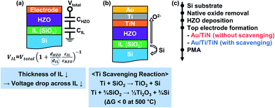
For HZO-based capacitors, HZO films (10 nm) were deposited by thermal atomic layer deposition (ALD) on highly doped n-Si wafers that were pre-treated with buffered oxide etchant (BOE). Tetrakis (ethylmethylamino) hafnium (TEMAHf) and tetrakis(ethylmethylamino) zirconium (TEMAZr) were used as precursors and ozone was injected as the oxidant. For all ALD processes, the deposition temperature was maintained at 270 °C. Then, top electrodes of Au (100 nm)/TiN (20 nm) and Au (80 nm)/Ti (20 nm)/TiN (20 nm) were formed. To induce crystallization and oxygen scavenging, post-metallization annealing (PMA) was carried out by rapid thermal annealing (RTA) for 1 minute at 400, 500, and 600 °C in an N2 atmosphere of 1 torr. The fabrication flow is depicted in Fig. 1c.Characterization of films
Cross-sectional view images of HZO-based capacitors were obtained by transmission electron microscopy (TEM; JEOL, JEM-ARM200F), with an accelerating voltage of 200 kV. The structural analysis of the phase and chemical bonding state of HZO films was performed by grazing incidence X-ray diffraction (GIXRD; Rigaku, SmartLab) and X-ray photoelectron spectroscopy (XPS; ThermoFisher Scientific, K-Alpha+).Electrical properties of devices were measured by using a parameter analyzer (Keithley, 4200A-SCS) with a pulse measurement unit (Keithley, 4225-PMU) and remote preamplifier/switch modules (Keithley, 4225-RPM). Pulse measurement schemes are presented in Fig. S2.† Fig. S2a† shows a typical polarization-voltage (P–V) hysteresis measurement using a bipolar triangular pulse and was used for switching voltage (Vsw) extraction. Fig. S2b† shows a positive-up-negative-down (PUND) method using double pulses, which separates polarization and capacitive charging by subtracting the current measured in the first pulse (P and N) and the second pulse (U and D). Endurance and retention tests were performed as shown in Fig. S2c and d.†
Results and discussion
Fabrication of HZO-based capacitors via oxygen scavenging
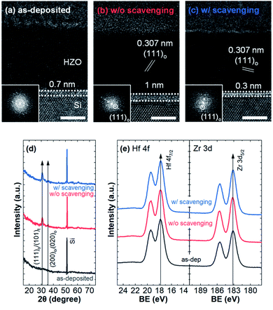
Fig. 1a presents the schematic image of the typical MFIS capacitors with HZO and Si with an equivalent circuit of series capacitors with the SiOx IL. Here, the voltage across the IL and HZO is distributed depending on the relative thicknesses and dielectric constants of the IL and HZO. The trend of voltage drop distribution between the IL and HZO according to the IL thickness (dIL) is plotted in Fig. S1a† based on the typical dielectric constants of 3.9 and 30,37 respectively. When the thickness of HZO (dHZO) is constant, a decrease in dIL leads to an increase in capacitance of the IL, thus, the voltage drop across the IL (VIL) will be decreased. Therefore, a reduction in dIL will promote FE switching by dominant voltage distribution across the HZO film. In addition, as shown in Fig. S1b,† the electric field across the IL is the same regardless of dIL, so there is no concern about severe electric field across the IL.Therefore, to ultimately reduce the IL at the interface between HZO and Si, we explored remote scavenging using Ti based on the reaction shown in Fig. 1b. Since Ti is thermodynamically favored to decompose SiO2 considering Gibbs free energy (Fig. 1b),38 we aimed remote oxygen scavenging by introducing Ti on a thin TiN electrode in the gate stack. TiN was used as a barrier layer to prevent Ti diffusion, the intermixing between Ti and HZO, and the capping effect to obtain the ferroelectric orthorhombic phase. Au was used as a capping layer to prevent external oxygen penetration during PMA from the atmosphere. To investigate the effect of oxygen scavenging, we fabricated Au/TiN/HZO/Si (without scavenging) and Au/Ti/TiN/HZO/Si (with scavenging) capacitors following the fabrication flow depicted in Fig. 1c and details are in the Experimental section. As shown in cross-sectional TEM images of Fig. 2a–c, we successfully reduced dIL without process temperature increase by oxygen scavenging with Ti metal. The dIL of the as-deposited capacitor was 0.7 nm despite removal by the buffered oxide etchant in the pre-treatment. Then, after PMA, the dIL increased to 1 nm in the capacitor without scavenging and remarkably decreased to 0.3 nm in the capacitor with scavenging, indicating that the IL re-grew and was scavenged by PMA, respectively. Consequently, according to the voltage drop distribution in Fig. S1a,† in the capacitor without scavenging, a voltage of 43% and 57% will be applied to the IL and HZO, respectively. In the capacitor with scavenging, the VIL will be reduced to 19%.
Meanwhile, the fast Fourier transform images shown in the insets of Fig. 2a–c reveal that PMA induced not only oxygen scavenging but also crystallization from the amorphous structure to poly-crystalline orthorhombic phase. The interplanar distance of 0.307 nm also matches well with the o(111) plane.39 For further structural analysis of HZO after PMA, GIXRD and XPS were performed. As shown in Fig. 2d, GIXRD peaks appeared at 30.8 and 35.5° only in w/o scavenging and scavenged HZO, implying that the amorphous structure of as-deposited HZO was transformed into a mixture of orthorhombic and tetragonal phases after PMA.40 In the XPS spectra of Hf 4f and Zr 3d binding energy levels shown in Fig. 2e, the Hf 4f7/2 and Zr 3d5/2 peaks appeared at 17.7 and 183.1 eV with peak differences of 1.71 and 2.43 eV, respectively, as previously reported in HZO films.41 Note that TEM, GIXRD, and XPS analyses showed no significant structural differences between the HZO film w/o scavenging and with scavenging. This is because HZO films are dominantly affected by the tensile stress induced by the top and bottom electrodes, in particular, the latter,42 but both electrodes of our HZO films were the same as TiN and highly doped n-Si. Therefore, it can be considered that the difference in electrical and FE properties to be discovered in device measurement in the following section mainly originates from the difference in the dIL.
Effect of oxygen scavenging on ferroelectricity of HZO-based capacitors
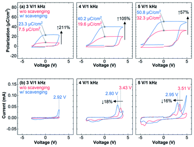
Detailed pulse measurement methods are depicted in the Experimental section and Fig. S2.† Based on Pr, Vsw, and leakage characteristics in the transient current (I–V) curves during the polarization switching and the polarization-voltage (P–V) hysteresis curves shown in Fig. S3 and S4,† the PMA temperature was optimized at 500 °C since PMA at 400 and 600 °C induced oxygen scavenging insufficiently and excessively, thus, the Vsw decreased slightly in the former and in the latter, the leakage increased significantly. Fig. 3a shows the results of the positive-up-negative-down (PUND) measurement of both capacitors, which can compensate for leakage and capacitive charging of FE by double triangular pulses (Fig. S2a†). Since the MFIS structure is asymmetric in structure and carrier response,17,43 the P–V curves are not centered and are displayed as measured. The capacitor with scavenging exhibited higher Pr than the capacitor without scavenging at the same pulse due to the lower Vsw resulting from the thinner IL. At a pulse of 4 V/1 kHz and 5 V/1 kHz, Pr of the capacitor with scavenging increased by 105 and 57% than that of the capacitor without scavenging, respectively. In particular, at a pulse of 3 V/1 kHz, Pr increased by 211%, indicating that a 3 V/1 kHz pulse can induce ferroelectric switching in the capacitor with scavenging but is insufficient in the capacitor without scavenging.Fig. 3b, I–V curves of capacitors without and with scavenging with the bipolar triangular pulse to the gate (Fig. S2b†), shows Vsw clearly. At a pulse of 4 V/1 kHz, capacitors without and with scavenging exhibited Vsw of 3.43 and 2.80 V, respectively, which means that Vsw was reduced by 16% by oxygen scavenging. According to the voltage drop distribution, VHZO at Vsw of capacitors without and with scavenging is 2.35 and 2.09 V, which is about 12% different. This is because the voltage drop distribution dominates the ferroelectric switching behavior but other factors such as charge-assisted polarization also play a role.22 Therefore, the EIL of the capacitor with scavenging at Vsw, which was the same as that of the capacitor without scavenging when only the voltage drop distribution is considered in Fig. S1b,† will be slightly higher than that of the capacitor without scavenging. But since the charge-assisted polarization is less in the capacitor with scavenging, the damage caused by trapping will be also less, and further measurements are required to compare reliability properties. The leakage characteristics of the capacitor with scavenging shown in I–V curves (Fig. 3b) will also affect the reliability. In other words, as the IL became thinner by oxygen scavenging, Vsw and charge trapping decreased while EIL and leakage increased. Nevertheless, it should be noted that the capacitor with scavenging can exhibit the same Pr as the capacitor without scavenging at a lower pulse amplitude, which can compensate the increased EIL and leakage.
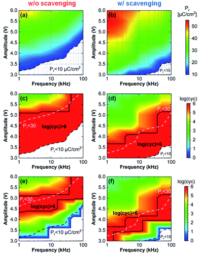
In order to investigate the effect of oxygen scavenging on the reliability of HZO-based capacitors, the endurance test was carried out (Fig. S2c†). Bipolar triangular pulses with an amplitude of 3 to 6 V and a frequency of 1 to 100 kHz were applied, and Pr extracted from the PUND method and endurance properties of capacitors without and with scavenging were mapped in Fig. 4. Fig. 4a and b mapped the Pr of capacitors without and with scavenging, but only Pr over 10 μC cm−2 (minimum Pr for MW to saturate in the FEFET)43 was displayed in color. Attributed to the much reduced Vsw of the capacitor with scavenging, the Pr map of the capacitor with scavenging shifted to a lower voltage than that of the capacitor without scavenging. Additionally, in both capacitors, higher amplitudes were required to obtain the same level of Pr at higher frequencies. On the endurance map in Fig. 4c–f, boundaries indicating initial Pr of 10 and 30 μC cm−2 derived from Fig. 4a and b were overlaid by black and white dashed lines, respectively. First, Fig. 4c and d are maps of the endurance cycles until breakdown occurred. The regions where breakdown did not occur until 106 cycles were marked by black solid lines. Note that although only 106 cycles are displayed for visibility of maps, breakdown did not occur until 109 cycles for the capacitors without and with scavenging at the pulses of 4.5 V/100 kHz and 3.5 V/100 kHz, respectively. Interestingly, this region tended to occur at initial Pr below 30 μC cm−2. For a multifaceted analysis of endurance properties, the endurance cycles until Pr reached 10 μC cm−2 were mapped in Fig. 4e and f because in device operation, maintaining Pr effectively is as important as breakdown not occurring. The regions in which Pr was maintained over 10 μC cm−2 until 106 cycles were also marked by black solid lines, and the regions spanned the lines with an initial Pr of 30 μC cm−2. Analysis of Pr and endurance maps showed that both capacitors exhibited high endurance properties, maintaining Pr over 10 μC cm−2 without breakdown until 106 cycles at moderate pulses. Otherwise, in specific pulses, the capacitor with scavenging showed superior endurance properties to the capacitor without scavenging due to the lowered Vsw. For instance, at 3.5 V/10 kHz, where capacitors without scavenging did not exhibit an initial Pr exceeding 10 μC cm−2, the capacitors with scavenging maintained Pr over 10 μC cm−2 until 106 cycles. At 4 V/10 kHz, capacitors without and with scavenging showed 103 and 106 cycles maintaining Pr over 10 μC cm−2. At 4.5 V/10 kHz, the capacitors without scavenging finally reached 106 cycles.
However, since both capacitors have different Vsw, we compare endurance properties based on the initial Pr rather than the applied pulse. The endurance properties until breakdown occurred and Pr decreased to 10 μC cm−2 according to initial Pr are shown in Fig. S6.† In both capacitors, breakdown did not occur up to 106 cycles at initial Pr below 30 μC cm−2 regardless of pulse frequency (Fig. S6a†). However, at lower initial Pr, Pr reached 10 μC cm−2 in earlier cycling (Fig. S6b†). The endurance measurement results according to initial Pr suggest that oxygen scavenging can effectively lower the Vsw while maintaining Pr without deteriorating the endurance properties of the HZO-based capacitors.
The endurance test proved that the endurance properties of the capacitor with scavenging were comparable to or even better than those of the capacitor without scavenging. As mentioned above, this is because Vsw and charge trapping decreased despite the increase in EIL and leakage by oxygen scavenging. Analysis of initial internal fields (Eint) and XPS can verify decreased charge trapping in the capacitor with scavenging. Referring to the imprint effect of the P–V curves in Fig. S7,† the Eint of the capacitors without and with scavenging was 0.277 and 0.385 MV cm−1, respectively, at a pulse of 6 V/10 kHz. The Eint can be readily calculated as the average of positive and negative Vsw. Since the direction of Eint is opposite to that of the P–V curve shift, the negative shift of the P–V curve is consistent with the direction of Eint from the top electrode to the bottom electrode. The Eint is formed inside the FE materials by the difference in the work function between the top electrode and the bottom electrode,44 the difference in the areal density of oxygen atoms at the interfacial oxide,45 and the asymmetric distribution of oxygen vacancies at the interface.46 However, in our capacitors without and with scavenging, the top electrode and the bottom electrode are the same as TiN and high-doped n-Si and the IL is also the same as SiO2. Thus, it seems that the differences in oxygen vacancy distribution at the top and bottom interfaces of both capacitors lead to different Eint. The sub-oxide peaks of the deconvoluted XPS Hf 4f spectra in Fig. S8† reveal that the existence of oxygen vacancies at the top interface and its density are similar in both capacitors. The fact that the initial Eint of the capacitor with scavenging was higher than that of the capacitor without scavenging suggests that the density of positively charged oxygen vacancies at the bottom interface of the capacitor with scavenging would be less than that of the capacitor without scavenging, which is consistent with the interpretation of charge-assisted polarization in Fig. 3b. The existence of oxygen vacancies at the top interface is because TiN of the top electrode generates oxygen vacancies at the top interface of HZO during the TiN deposition process and PMA.42 On the other hand, as shown in Fig. S7,† the Eint of capacitors without and with scavenging negatively shifted to −1.155 and −0.479 MV cm−1, respectively, after endurance tests of 103 and 102 cycles at 6 V/10 kHz, which means that oxygen vacancies are drastically generated at the bottom interface during cycling. This negative imprint shift indicates the endurance issue due to IL degradation caused by charge trapping in the IL of the MFIS structure.47 In addition, despite the oxygen vacancy distribution differing by 15% between pristine capacitors without and with scavenging, the wake-up and fatigue, a gradual increase and decrease in Pr with cycling, which is a typical phenomenon in ferroelectric HZO, were similar to that shown in Fig. S5.† Since wake-up and fatigue are closely related to domain pining/de-pinning and oxygen vacancy redistribution,48 it is suggested that these phenomena are not significantly different between capacitors without and with scavenging. It was found that oxygen scavenging adversely affected not only endurance properties but also wake-up and fatigue, which are undesirable for the reliability of long-term device operation.
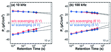
Finally, the retention of Pr was measured for positive and negative poling voltages at room temperature for low-temperature characterization and presented in Fig. 5. The data that were measured by pulses (5 V/10 kHz and 6 V/100 kHz for capacitors without scavenging and 4 V/10 kHz and 5 V/100 kHz for capacitors with scavenging) with similar initial Pr while exhibiting endurance properties of higher than 106 cycles in both capacitors were extrapolated up to 10 years. In positive poling with 5 V/10 kHz and 4 V/10 kHz pulses, the retention properties at 10 years of both capacitors were stable, with Pr exceeding 20 μC cm−2 and maintaining 73 and 87% in capacitors without and with scavenging, respectively. In contrast, retention was not only relatively unstable in negative poling, but there was also a large gap between capacitors without and with scavenging. The Pr of capacitors without scavenging decreased to 22 and 17% and was less than 10 μC cm−2 at 10 year retention extrapolation in negative poling with 5 V/10 kHz and 6 V/100 kHz pulses while capacitors with scavenging showed Pr over 10 μC cm−2 and kept it at 55 and 37% at 4 V/10 kHz and 5 V/100 kHz. The unstable retention characteristics in negative poling are due to electron trapping that occurs in positive pulses. In the typical MFIS structure, the behavior of electrons and holes is asymmetric. As a large amount of electrons (∼1014 cm−2)43 trapped in positive pulses are gradually detrapped according to the retention time,17 the retention characteristics of Pr become unstable. Therefore, the superior retention characteristics of capacitors with scavenging over capacitors without scavenging are attributed to the lower depolarization field54 and less charge trapping owing to the thinner IL.
Potential of oxygen scavenging in HZO-based devices
Uniformity was acquired to validate the potential of oxygen scavenging for industrial applications. The spatial distribution maps of Vsw and Pr of 25 capacitors without and with scavenging in an area of 1 × 1 cm2 are displayed in Fig. 6. Pulses of 5 V/1 kHz and 4 V/1 kHz were applied to capacitors without and with scavenging. Fig. 6a and b present that the average Vsw of capacitors without and with scavenging was 3.48 and 2.91 V with very small standard deviations of 0.038 V and 0.034 V, respectively. The average Pr extracted from the PUND method of capacitors without and with scavenging was 32.1 and 40.3 μC cm−2 with standard deviations of 1.01 and 1.13 μC cm−2, respectively (Fig. 6c and d). In Fig. S9,† the detailed Vsw and Pr of 25 capacitors without and with scavenging are shown. The excellent uniformity and high yield of capacitors with scavenging confirmed by quantitative results indicate that oxygen scavenging does not impair uniformity and is suitable for large-area fabrication.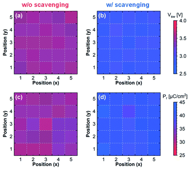 | ||
| Fig. 6 Uniformity maps of (a), (b) Vsw and (c), (d) Pr of capacitors without and with scavenging. 25 capacitors for each were measured in an area of 1 × 1 cm2. | ||
Furthermore, the benchmark in Table 1 highlights the low-voltage operation and high endurance properties of our capacitors with scavenging. In the MFIS structure, we achieved a high Pr of 28 μC cm−2 and endurance properties of >106 cycles maintaining Pr higher than 10 μC cm−2 at a pulse of 4 V/10 kHz with annealing at a low temperature of 500 °C via oxygen scavenging. The capacitor with scavenging showed outstanding performances compared to the capacitor without scavenging as well as other previous MFIS structures.32,49–53
| This work | 49 | 50 | 51 | 32 | 52 | 53 | ||
|---|---|---|---|---|---|---|---|---|
| With scavenging | Without scavenging | |||||||
| Ferroelectric oxide (thickness [nm]) | HZO (10) | HZO (10) | Al:HfO2 (20) | HZO (20) | HfO2 (10) | HZO (10) | HZO (13) | HZO (10) |
| PMA temperature [°C] | 500 | 500 | 900 | 600 | N/A | 500 | 750 | 700 |
| Pulse amplitude [V] | 4 | 4 | 10 | 6 | 3 | 4 | 4 | 2 |
| Pulse frequency [kHz] | 10 | 10 | N/A | N/A | N/A | 1 | 1 | N/A |
| P r [μC cm−2] | 28 | 16 | 40 | 25 | 8 | 35 | 45 | N/A |
| Endurance until breakdown [cycles] | >106 | >106 | >104 | >105 | 105 | 106 | 103 | >107 |
| Endurance until Pr > 10 μC cm−2 [cycles] | >106 | >103 | >104 | >105 | 0 | 106 | 103 | N/A |
Conclusions
We demonstrated oxygen scavenging by introducing Ti metal in the top electrode stack to improve the performance of HZO-based devices. The reduction in IL thickness via oxygen scavenging was manifested by TEM cross-sectional images, and no structural difference between w/o scavenging and scavenged HZO films was observed in XRD and XPS analyses. The capacitors with scavenging exhibited low-voltage operation and excellent endurance and retention properties. The Vsw was decreased by 18%, from 3.43 V to 2.80 V for capacitors without and with scavenging, respectively. Due to the lower Vsw, the same Pr could be obtained at a lower voltage than the capacitor without scavenging. In addition, the capacitor with scavenging showed endurance properties exceeding 106 cycles while maintaining Pr higher than 10 μC cm−2 without breakdown, which was superior to the capacitor without scavenging showing 103 cycles. 10 year retention and uniformity were also confirmed. Finally, we believe that oxygen scavenging has great potential to improve the FE properties of HZO-based devices.Conflicts of interest
There are no conflicts to declare.Acknowledgements
This work was supported by the NRF grant (No. 2019M3F3A1A02072072 and 2020M3F3A2A01110575), BK21 FOUR, KAIST for PIM (N11220038), and the IC Design Education Center.References
- J. Valasek, Phys. Rev., 1921, 17, 475 CrossRef CAS.
- J. Müller, T. Böscke, D. Bräuhaus, U. Schröder, U. Böttger, J. Sundqvist, P. Kücher, T. Mikolajick and L. Frey, Appl. Phys. Lett., 2011, 99, 112901 CrossRef.
- P. Polakowski and J. Müller, Appl. Phys. Lett., 2015, 106, 232905 CrossRef.
- K. Kim, M. Park, H. Kim, Y. Kim, T. Moon, Y. Lee, S. Hyun, T. Gwon and C. Hwang, J. Mater. Chem. C, 2016, 4, 6864–6872 RSC.
- A. Pal, V. K. Narasimhan, S. Weeks, K. Littau, D. Pramanik and T. Chiang, Appl. Phys. Lett., 2017, 110, 022903 CrossRef.
- H. Chen, Y. Chen, L. Tang, H. Luo, K. Zhou, X. Yuan and D. Zhang, J. Mater. Chem. C, 2020, 8, 2820–2826 RSC.
- K. Lee, T. Y. Lee, S. M. Yang, D. H. Lee, J. Park and S. C. Chae, Appl. Phys. Lett., 2018, 112, 202901 CrossRef.
- S. Vulpe, F. Nastase, M. Dragoman, A. Dinescu, C. Romanitan, S. Iftimie, A. Moldovan and N. Apostol, Appl. Surf. Sci., 2019, 483, 324–333 CrossRef CAS.
- H. Mulaosmanovic, E. T. Breyer, T. Mikolajick and S. Slesazeck, IEEE Trans. Electron Devices, 2019, 66, 3828–3833 CAS.
- F. Mehmood, M. Hoffmann, P. D. Lomenzo, C. Richter, M. Materano, T. Mikolajick and U. Schroeder, Adv. Mater. Interfaces, 2019, 6, 1901180 CrossRef CAS.
- M. H. Park, H. J. Kim, Y. J. Kim, W. Lee, T. Moon and C. S. Hwang, Appl. Phys. Lett., 2013, 102, 242905 CrossRef.
- S. Zarubin, E. Suvorova, M. Spiridonov, D. Negrov, A. Chernikova, A. Markeev and A. Zenkevich, Appl. Phys. Lett., 2016, 109, 192903 CrossRef.
- M. H. Park, Y. H. Lee, H. J. Kim, T. Schenk, W. Lee, K. Do Kim, F. P. Fengler, T. Mikolajick, U. Schroeder and C. S. Hwang, Nanoscale, 2017, 9, 9973–9986 RSC.
- M. G. Kozodaev, A. G. Chernikova, E. V. Korostylev, M. H. Park, R. R. Khakimov, C. S. Hwang and A. M. Markeev, J. Appl. Phys., 2019, 125, 034101 CrossRef.
- S. L. Weeks, A. Pal, V. K. Narasimhan, K. A. Littau and T. Chiang, ACS Appl. Mater. Interfaces, 2017, 9, 13440–13447 CrossRef CAS PubMed.
- K. Toprasertpong, M. Takenaka, and S. Takagi in 2019 IEEE International Electron Devices Meeting (IEDM), 2019, pp. 23.27.21–23.27.24 Search PubMed.
- S.-H. Kuk, S.-M. Han, B.-H. Kim, S.-H. Baek, J.-H. Han, and S.-H. Kim in 2021 IEEE International Electron Devices Meeting (IEDM), 2021, pp. 33.36.31–33.36.34 Search PubMed.
- K. Ni, P. Sharma, J. Zhang, M. Jerry, J. A. Smith, K. Tapily, R. Clark, S. Mahapatra and S. Datta, IEEE Trans. Electron Devices, 2018, 65, 2461–2469 CAS.
- D. Zhao, T. Lenz, G. H. Gelinck, P. Groen, D. Damjanovic, D. M. de Leeuw and I. Katsouras, Nat. Commun., 2019, 10, 1–11 CrossRef PubMed.
- J. Lyu, I. Fina and F. Sanchez, Appl. Phys. Lett., 2020, 117, 072901 CrossRef CAS.
- K. K. Min, J. Yu, Y. Kim, J.-H. Lee, D. Kwon and B.-G. Park, Nanotechnology, 2021, 32, 495203 CrossRef CAS PubMed.
- T. Kim and C. Shin, Electronics, 2020, 9, 2141 CrossRef CAS.
- W. Xiao, C. Liu, Y. Peng, S. Zheng, Q. Feng, C. Zhang, J. Zhang, Y. Hao, M. Liao and Y. Zhou, IEEE Electron Device Lett., 2019, 40, 714–717 CAS.
- M. H. Park, Y. H. Lee, H. J. Kim, Y. J. Kim, T. Moon, K. D. Kim, J. Mueller, A. Kersch, U. Schroeder and T. Mikolajick, Adv. Mater., 2015, 27, 1811–1831 CrossRef CAS PubMed.
- K. Tahara, K. Toprasertpong, Y. Hikosaka, K. Nakamura, H. Saito, M. Takenaka, and S. Takagi in 2021 IEEE Symposium on VLSI Technology, 2021, p. 1 Search PubMed.
- S. J. Kim, J. Mohan, J. Lee, J. S. Lee, A. T. Lucero, C. D. Young, L. Colombo, S. R. Summerfelt, T. San and J. Kim, Appl. Phys. Lett., 2018, 112, 172902 CrossRef.
- W. Xiao, C. Liu, Y. Peng, S. Zheng, Q. Feng, C. Zhang, J. Zhang, Y. Hao, M. Liao and Y. Zhou, Nanoscale Res. Lett., 2019, 14, 1–7 CrossRef CAS PubMed.
- Y.-H. Chen, C.-J. Su, C. Hu and T.-L. Wu, IEEE Electron Device Lett., 2019, 40, 467–470 CAS.
- Y.-H. Chen, C.-J. Su, T.-H. Yang, C. Hu and T.-L. Wu, IEEE Trans. Electron Devices, 2020, 67, 1581–1585 CAS.
- T. Ali, P. Polakowski, S. Riedel, T. Büttner, T. Kämpfe, M. Rudolph, B. Pätzold, K. Seidel, D. Löhr and R. Hoffmann, IEEE Trans. Electron Devices, 2018, 65, 3769–3774 CAS.
- A. J. Tan, Y.-H. Liao, L.-C. Wang, N. Shanker, J.-H. Bae, C. Hu and S. Salahuddin, IEEE Electron Device Lett., 2021, 42, 994–997 CAS.
- K.-Y. Chen, Y.-H. Huang, R.-W. Kao, Y.-X. Lin, K.-Y. Hsieh and Y.-H. Wu, IEEE Trans. Electron Devices, 2019, 66, 3636–3639 CAS.
- Y. Goh, S. H. Cho, S.-H. K. Park and S. Jeon, Nanoscale, 2020, 12, 9024–9031 RSC.
- F. Zhang, Z.-D. Luo, Q. Yang, J. Zhou, J. Wang, Z. Zhang, Q. Fan, Y. Peng, Z. Wu and F. Liu, ACS Appl. Mater. Interfaces, 2022, 14, 11028–11037 CrossRef CAS PubMed.
- Y. B. Lee, B. Y. Kim, H. W. Park, S. H. Lee, M. Oh, S. K. Ryoo, I. S. Lee, S. Byun, D. Shim and J. H. Lee, Adv. Electron. Mater., 2022, 2200310 CrossRef.
- S. Fujii, M. Yamaguchi, S. Kabuyanagi, K. Ota, and M. Saitoh in 2020 IEEE Symposium on VLSI Technology, 2020, pp. 1–2 Search PubMed.
- T. Böscke, P. Hung, P. Kirsch, M. Quevedo-Lopez and R. Ramírez-Bon, Appl. Phys. Lett., 2009, 95, 052904 CrossRef.
- D. R. Lide, CRC Handbook of Chemistry and Physics, CRC Press, 2004 Search PubMed.
- T.-J. Chang, C. Liu, C.-C. Fan, H.-H. Hsu, H.-H. Chen, W.-H. Chen, Y.-C. Fan, T.-M. Lee, C.-L. Lin and J. Ma, Vacuum, 2019, 166, 11–14 CrossRef CAS.
- S. H. Kim, G. T. Yu, G. H. Park, D. H. Lee, J. Y. Park, K. Yang, E. B. Lee, J. I. Lee and M. H. Park, Chem. Commun., 2021, 57, 12452–12455 RSC.
- Y. Peng, G. Han, W. Xiao, Y. Liu, Q. Li, C. Zhang, J. Zhang and Y. Hao, Superlattices Microstruct., 2019, 130, 519–527 CrossRef CAS.
- Y. Lee, Y. Goh, J. Hwang, D. Das and S. Jeon, IEEE Trans. Electron Devices, 2021, 68, 523–528 CAS.
- K. Toprasertpong, Z. Lin, T. Lee, M. Takenaka, and S. Takagi in 2020 IEEE Symposium on VLSI Technology, 2020, pp. 1–2 Search PubMed.
- F. Liu, I. Fina, R. Bertacco and J. Fontcuberta, Sci. Rep., 2016, 6, 1–7 CrossRef PubMed.
- K. Kita and A. Toriumi, Appl. Phys. Lett., 2009, 94, 132902 CrossRef.
- M. Park, H. Kim, Y. Kim, T. Moon, K. Kim, Y. Lee, S. Hyun and C. Hwang, J. Mater. Chem. C, 2015, 3, 6291–6300 RSC.
- N. Gong and T.-P. Ma, IEEE Electron Device Lett., 2017, 39, 15–18 Search PubMed.
- S. Li, D. Zhou, Z. Shi, M. Hoffmann, T. Mikolajick and U. Schroeder, Adv. Electron. Mater., 2020, 6, 2000264 CrossRef CAS.
- H. Ryu, K. Xu, J. Guo, and W. Zhu in 2018 76th Device Research Conference (DRC), 2018, pp. 1–2 Search PubMed.
- H. Ryu, K. Xu, D. Kim, F. Rao, and W. Zhu in 49th IEEE Semiconductor Interface Specialists Conference, 2018 Search PubMed.
- Y.-T. Lee, H.-H. Chen, Y.-C. Tung, B.-Y. Shih, S.-Y. Hsiung, T.-M. Lee, C.-C. Hsu, C. Liu, H.-H. Hsu, and C.-Y. Chang in 2019 IEEE International Conference on Electron Devices and Solid-State Circuits (EDSSC), 2019, pp. 1–3 Search PubMed.
- C. Zacharaki, P. Tsipas, S. Chaitoglou, S. Fragkos, M. Axiotis, A. Lagoyiannis, R. Negrea, L. Pintilie and A. Dimoulas, Appl. Phys. Lett., 2019, 114, 112901 CrossRef.
- H.-H. Hsu, H.-M. Liu and S. Lee, Coatings, 2020, 10, 733 CrossRef CAS.
- M. Lederer, K. Mertens, A. M. Kia, J. Emara, R. Olivo, Y. Raffel, D. Lehninger, T. Ali, K. Kühnel and K. Seidel, MRS Adv., 2021, 6, 525–529 CrossRef CAS.
Footnote |
| † Electronic supplementary information (ESI) available. See https://doi.org/10.1039/d2na00533f |
| This journal is © The Royal Society of Chemistry 2022 |

