
 Open Access Article
 This Open Access Article is licensed under a Creative Commons Attribution-Non Commercial 3.0 Unported Licence
TiO2 nanotubular arrays decorated with ultrafine Ag nanoseeds enabling a stable and dendrite-free lithium metal anode†
Yulei
Li
a,
Shenhao
Li
a,
Jiewu
Cui
 a,
Jian
Yan
a,
Hark Hoe
Tan
b,
Jiaqin
Liu
*a and
Yucheng
Wu
*a
a,
Jian
Yan
a,
Hark Hoe
Tan
b,
Jiaqin
Liu
*a and
Yucheng
Wu
*a
aInstitute of Industry & Equipment Technology, School of Materials Science and Engineering, Engineering Research Center of Advanced Composite Materials Design & Application of Anhui Province, Key Laboratory of Advanced Functional Materials & Devices of Anhui Province, Hefei University of Technology, Hefei, 230009, China. E-mail: jqliu@hfut.edu.cn
bDepartment of Electronic Materials Engineering, Research School of Physics and Engineering, Australian National University, Canberra, ACT 2601, Australia
First published on 7th October 2022
Abstract
To exploit next-generation high-energy Li metal batteries, it is vitally important to settle the issue of dendrite growth accompanied by interfacial instability of the Li anode. Applying 3D current collectors as hosts for Li deposition emerges as a prospective strategy to achieve uniform Li nucleation and suppress Li dendrites. Herein, well-aligned and spaced TiO2 nanotube arrays grown on Ti foil and surface decorated with dispersed Ag nanocrystals (Ag@TNTAs/Ti) were constructed and employed as a 3D host for regulating Li stripping/plating behaviors and suppressing Li dendrites, and also relieving volume fluctuation during repetitive Li plating/stripping. Uniform TiO2 nanotubular structures with a large surface allow fast electron/ion transport and uniform local current density distribution, leading to homogeneous Li growth on the nanotube surface. Moreover, Ag nanocrystals and TiO2 nanotubes have good Li affinity, which facilitates Li+ capture and reduces the Li nucleation barrier, achieving uniform nucleation and growth of Li metal over the 3D Ag@TNTAs/Ti host. As a result, the as-fabricated Ag@TNTAs/Ti electrode exhibits dendrite-free plating morphology and long-term cycle stability with coulombic efficiency maintained over 98.5% even after 1000 cycles at a current density of 1 mA cm−2 and cycling capacity of 1 mA h cm−2. In symmetric cells, the Ag@TNTAs/Ti–Li electrode shows a much lower hysteresis of 40 mV over an ultralong cycle period of 2600 h at a current density of 1 mA cm−2 and cycling capacity of 1 mA h cm−2. Moreover, the full cell with the Ag@TNTAs/Ti–Li anode and LiFePO4 cathode achieves a high capacity of 155.2 mA h g−1 at 0.5C and retains 77.9% capacity with an average CE of ≈99.7% over 200 cycles.
1 Introduction
Lithium metal is recognized as the most ideal anode material for next-generation rechargeable batteries (such as Li–O2 and Li–S batteries) owing to its ultrahigh theoretical specific capacity of 3860 mA h g−1, lowest density of 0.59 g cm−2, and the lowest reduction potential of −3.04 V (vs. standard hydrogen electrode).1,2 Unfortunately, practical application of Li metal anodes still confronts several severe challenges, especially uncontrollable Li dendrite formation, unstable solid electrolyte interphase (SEI), and infinite volume fluctuation during cyclic plating/stripping of Li metal,3–5 which leads to low coulombic efficiency (CE) and short cycling lifespan accompanied by safety risks.Various strategies have been developed to tackle these issues, including introduction of electrolyte additives, artificial SEI layers, solid-state electrolytes, three-dimensional (3D) hosts for Li metal, etc.6–9 Thereinto, constructing a 3D composite Li anode by hosting Li metal into a 3D lithiophilic scaffold has been demonstrated to be a simple and highly effective approach. The high surface area of 3D hosts greatly lowers the local current density and thereby suppresses the Li dendrite formation according to Sand's formula.10–12 Furthermore, the 3D porous scaffold offers confined space to host deposited Li, accommodating significant volume changes during the Li plating/stripping process. Nevertheless, most of the 3D host materials, such as carbon and metal materials, display poor Li affinity, leading to high Li nucleation overpotential and unfavorable Li deposition on these 3D hosts. Heterogeneous Li nucleation and growth opens up a new perspective of regulating Li metal deposition behavior on 3D host structures.13,14 Heterogeneous nanocrystals with zero overpotential for Li nucleation, typically silver and gold nanoparticles (NPs),15–17 are modified on the surface of the 3D skeleton and serve as nucleation seeds to enable uniform nucleation and growth of Li metal, thus effectively constraining the Li dendrite growth. It's reported that these metal nanoparticles anchored on the 3D skeleton surface are directly reacted with Li-ions to form solid solution alloys (Li–Ag, Li–Au alloys) during the initial stage of electrodeposition,16,18 thus favoring Li deposition onto 3D hosts.
Nanofabrication technology provides new avenues for developing innovative host structures to address the issues of Li nucleation and interfacial instability of the Li anode. A rationally designed structure of 3D hosts is important for constructing a high-performance composite Li anode. Vertically aligned nanostructures could effectively facilitate Li+ transport to the electroactive sites during plating/stripping and enhance charge transfer kinetics. Recently, various stable Li metal anodes have been developed via hosting Li into vertically aligned nanostructures.19–21 Such hosts were usually prepared by growing ordered nanotubes or nanowires on the surface of different carbon or metal substrates. It's widely known that TiO2 nanotube arrays (TNTAs) are widely used as host materials in many applications owing to their strong chemical stability, large surface area, and easy fabrication.22–24 Surface lithiophilic modification of the 3D scaffold could facilitate Li+ capture and reduce the Li nucleation energy barrier.25,26 A stable and dendrite-free composite Li anode may be achieved by applying TiO2 nanotube arrays decorated with dispersed Ag nanocrystals as a 3D host for Li deposition.
Herein, well-aligned and spaced TiO2 nanotube arrays were grown on Ti foil and surface decorated with ultrafine Ag nanocrystals (Ag@TNTAs/Ti) by anodization combined with an impregnation approach. Then, such 3D architecture was employed as a space-confined host for Li metal deposition. First, uniform TiO2 nanotubular structures with a large surface allow fast electron/ion transport and uniform local current density distribution, leading to homogeneous Li growth on the nanotube surface. Second, Ag nanocrystals and TiO2 nanotubes show good Li affinity, which promotes Li+ capture and reduces the Li nucleation barrier, enabling uniform nucleation and growth of Li metal over the 3D Ag@TNTAs/Ti scaffold. Third, such a 3D host confines Li plating within ordered nanotubular structures to restrain volume expansion associated with Li plating/stripping. As a consequence, the Ag@TNTAs/Ti electrode exhibits a dendrite-free plating morphology and operates steadily for more than 1000 cycles with a CE of over 98.5% at a current density of 1 mA cm−2 and cycling capacity of 1 mA h cm−2. Remarkably, the Ag@TNTAs/Ti–Li electrode exhibits a substantially reduced hysteresis of 40 mV over an ultralong cycle period of 2600 h at a current density of 1 mA cm−2 and cycling capacity of 1 mA h cm−2 in symmetric cells. Moreover, the full cell with the Ag@TNTAs/Ti–Li anode and LiFePO4 cathode achieves a high capacity of 155.2 mA h g−1 at 0.5C and retains 77.9% capacity with an average CE of ≈99.7% over 200 cycles.
2 Experimental section
2.1 Preparation of TNTAs/Ti
Well-aligned and spaced TiO2 nanotube arrays (TNTAs) were directly grown on Ti foil (0.1 mm, 99.7%) by simple electrochemical anodization,27 and were studied in a two-electrode setup under a constant voltage of 60 V for 6 h in an ice bath with the Ti foil as the working electrode, graphite foil as the counter electrode, and a solution of 0.25 mol L−1 NH4F in ethylene glycol with 7 vol% H2O as the electrolyte. After anodization, the as-prepared samples were annealed at 500 °C for 2 h in an Ar atmosphere to obtain the TNTAs/Ti.2.2 Preparation of Ag@TNTAs/Ti
Ag NPs were dispersedly deposited onto the inner and outer walls of highly ordered and spaced TiO2 nanotubes using the cyclic impregnation method to obtain the Ag@TNTAs/Ti. First, the silver ammonia solution was pre-prepared by adding ammonia into a 30 mM AgNO3 solution dropwise until the resulting precipitates just disappeared. Meanwhile, a solution of 36 vol% formaldehyde was also prepared in advance. Then, the TNTAs/Ti were sequentially impregnated into the silver ammonia and formaldehyde solution for 30 seconds, and the above impregnation procedure was repeated three times. Finally, the resulting samples were washed and dried to obtain Ag@TNTAs/Ti.2.3 Materials characterization
Morphologies and structural features of the samples were observed using a field emission scanning electron microscope (FESEM, ZEISS Sigma 300). The elemental analysis was conducted using energy dispersive X-ray spectroscopy (EDX, X-Max50 Oxford). The crystalline structures were examined using an X-ray diffractometer (D/Max-2500 V, Rigaku) with CuKα-radiation (λ = 0.154056 nm) at a scanning rate of 2° min−1. X-ray photoelectron spectroscopy (XPS, ESCALAB 250Xi, Thermo Scientific) was used to characterize the surface composition and chemical states.2.4 Electrochemical measurements
Standard CR2032 coin cells were assembled in an Ar-filled glove box with both H2O and O2 concentrations below 0.1 ppm. 1.0 M lithium bis(trifluoromethanesulfonyl)imide (LiTFSI) in 1,2-dimethoxymethane (DME)/1,3-dioxolane (DOL) solvent (volume ratio of 1![[thin space (1/6-em)]](https://www.rsc.org/images/entities/char_2009.gif) :1) with 2.0 wt% LiNO3 was used as the electrolyte. To compare the Li nucleation barrier and coulombic efficiency (CE) of the Li plating/stripping process, Li|Ti, Li|TNTAs/Ti, and Li|Ag@TNTAs/Ti half cells were assembled by placing the Li foil, polypropylene membrane (PP, Celgard 2500), and Ti foil, TNTAs/Ti, or Ag@TNTAs/Ti in the sandwich structure. The half cells were tested at 1.0 mA cm−2 for 1.0 mA h cm−2 and 2.0 mA cm−2 for 2.0 mA h cm−2, and prior to testing, all cells were first discharged to 0.01 V and cycled within the potential of 0.01–1.0 V to complete the surface lithiation and electrode activation. Meanwhile, to probe the Li stripping/plating behavior, symmetric cell configurations were assembled with two identical Ti–Li, TNTAs/Ti–Li, or Ag@TNTAs/Ti–Li electrodes prepared by plating 3 mA h cm−2 Li onto the Ti foil, TNTAs/Ti, or Ag@TNTAs/Ti at 1 mA cm−2. To examine the full cell performance, a LiFePO4 (LFP) electrode at a mass loading of 3.0 mg cm−2 was prepared to couple with the above TNTAs/Ti–Li and Ag@TNTAs/Ti–Li electrodes pre-deposited with 3 mA h cm−2 Li. The galvanostatic charge/discharge (GCD) testing for full cells was conducted from 2.4 to 4.2 V on a LAND battery test system (Wuhan Land Electronic Co. Ltd.). Cyclic voltammetry (CV) and electrochemical impedance spectroscopy (EIS) tests were carried out on an Autolab PGSTAT302N electrochemical workstation. CV tests were performed at a scan rate of 0.1 mV s−1. EIS spectra were collected in the frequency range from 100 kHz to 10 mHz at an amplitude of 5 mV s−1.
:1) with 2.0 wt% LiNO3 was used as the electrolyte. To compare the Li nucleation barrier and coulombic efficiency (CE) of the Li plating/stripping process, Li|Ti, Li|TNTAs/Ti, and Li|Ag@TNTAs/Ti half cells were assembled by placing the Li foil, polypropylene membrane (PP, Celgard 2500), and Ti foil, TNTAs/Ti, or Ag@TNTAs/Ti in the sandwich structure. The half cells were tested at 1.0 mA cm−2 for 1.0 mA h cm−2 and 2.0 mA cm−2 for 2.0 mA h cm−2, and prior to testing, all cells were first discharged to 0.01 V and cycled within the potential of 0.01–1.0 V to complete the surface lithiation and electrode activation. Meanwhile, to probe the Li stripping/plating behavior, symmetric cell configurations were assembled with two identical Ti–Li, TNTAs/Ti–Li, or Ag@TNTAs/Ti–Li electrodes prepared by plating 3 mA h cm−2 Li onto the Ti foil, TNTAs/Ti, or Ag@TNTAs/Ti at 1 mA cm−2. To examine the full cell performance, a LiFePO4 (LFP) electrode at a mass loading of 3.0 mg cm−2 was prepared to couple with the above TNTAs/Ti–Li and Ag@TNTAs/Ti–Li electrodes pre-deposited with 3 mA h cm−2 Li. The galvanostatic charge/discharge (GCD) testing for full cells was conducted from 2.4 to 4.2 V on a LAND battery test system (Wuhan Land Electronic Co. Ltd.). Cyclic voltammetry (CV) and electrochemical impedance spectroscopy (EIS) tests were carried out on an Autolab PGSTAT302N electrochemical workstation. CV tests were performed at a scan rate of 0.1 mV s−1. EIS spectra were collected in the frequency range from 100 kHz to 10 mHz at an amplitude of 5 mV s−1.
2.5 Computational methods
All density functional theory (DFT) calculations were performed using the Dmol3 program in Materials Studio 7.0.28,29 The exchange-correlation functional was treated using the Perdew–Burke–Ernzerhof (PBE) functional with generalized gradient approximation (GGA).30 The Tkatchenko–Scheffler (TS) method for dispersion correction (DFT-D) was employed to better describe the long-range vdW interactions,31 and the double numerical plus polarization (DNP) was used as the orbital basis set.32 The convergence criteria for geometry optimization and energy calculation were set to 2.0 × 10⁻⁵ Ha, 4.0 × 10⁻³ Ha Å−1, and 5.0 × 10⁻³ Å for the tolerance of energy, force, and displacement, respectively, with a global orbital cut-off radius of 4.5 Å to achieve high-quality results. The anatase TiO2 (101) and Ag (111) surface were modeled using a 2 × 3 × 1 and 4 × 4 × 1 supercell, respectively. A vacuum layer of 20 Å was set to avoid interactions between the adjacent slabs. The surface Brillouin-zone was sampled by the 3 × 3 × 1 Monkhorst–Pack grid.33 The adsorption energy (Ead) between the Li atom and the TiO2 or Ag surface was calculated according to the formula of Ead = ELi@slab − ELi − Eslab, and ELi@slab, ELi and Eslab are the DFT energies of the total binding system, freestanding Li and slab, respectively.3 Results and discussion
Ag@TNTAs/Ti was achieved by anodization of Ti foil combined with cyclic impregnation for decoration of Ag NPs. XRD was performed to identify the phase structures of TNTAs/Ti and Ag@TNTAs/Ti (Fig. 1a). In the pattern of TNTAs/Ti, apart from the diffraction peaks of the Ti substrate, characteristic peaks at 25.3°, 37.9°, 48.1° and 53.9° correspond to the (101), (004), (200) and (105) planes of anatase TiO2 (JCPDS: 71-1166). This manifests that anatase TNTAs on Ti foil was achieved by anodization followed by annealing at 500 °C. In the XRD pattern of Ag@TNTAs/Ti, in addition to the characteristic peaks from Ti foil and anatase TNTAs, diffraction peaks at 38.1° and 44.3° are indexed to the (111) and (200) planes of Ag (JCPDS: 04-0783). The surface compositional and chemical states of Ag@TNTAs/Ti were further investigated by XPS (Fig. 1b–d and S1†). The survey spectrum indicates that it contains not only Ti and O elements from TNTAs, but also the Ag element from deposited Ag NPs and the C element from surface contaminated carbon species. Two peaks at 458.9 eV and 464.5 eV are assigned to the Ti 2p3/2 and Ti 2p1/2 of Ti4+ in TiO2,34,35 and two peaks at 529.8 eV and 531.6 eV correspond to the lattice oxygen of TiO2 and surface –OH groups.36 The binding energies at 367.8 eV and 373.7 eV are attributed to the Ag 3d5/2 and Ag 3d3/2 peaks of the metallic Ag 3d state.37 Morphologies of TNTAs/Ti and Ag@TNTAs/Ti were inspected using SEM observation. For TNTAs/Ti, highly-ordered and well-spaced TiO2 nanotube arrays with a length of around 8 μm, an inner diameter of 150–180 nm, a tube spacing of 20–30 nm, and a wall thickness of 20–25 nm are directly grown vertically on the Ti substrate (Fig. S3†). Such ordered arrays with well-defined tube spacings may provide fast Li+ migration channels as well as plenty of space to accommodate Li deposition and relieve volume changes during lithium deposition/dissolution. For Ag@TNTAs/Ti, large amounts of Ag NPs with size distribution from several to a dozen nanometers are tightly and diffusely anchored on the inner and outer wall of TiO2 nanotubes from the top to the bottom (Fig. 1e, f and S4†). Also, the elemental mapping of Ag, Ti and O (match with Fig. 1f) demonstrates the uniform distribution of Ag NPs on the walls of TiO2 nanotubes with a mass content of around 4.9% (Fig. 1g and S5†). Clearly, such tiny Ag NPs won't cause tube blocking and the decrease of tube spacing. Lithiophilic Ag NPs anchored on the tube walls may not only improve the conductivity of the electrode, but also reduce the overpotential of Li nucleation. Hopefully, such a nanocomposite array framework may realize a dendrite-free morphology of the Li metal anode.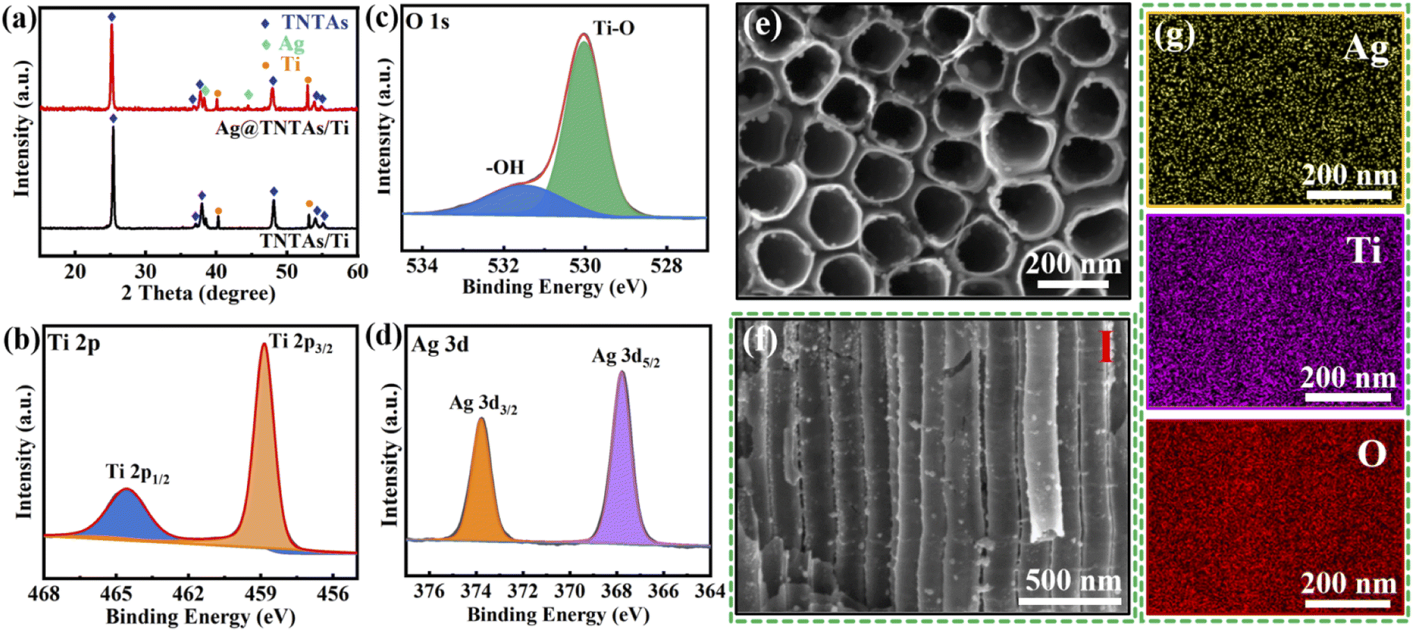 | ||
| Fig. 1 (a) XRD patterns of Ag@TNTAs/Ti and TNTAs/Ti; Ti 2p (b), O 1s (c) and Ag 3d (d) XPS spectra of the Ag@TNTAs/Ti; top-view (e) and side-view (f) SEM images of Ag@TNTAs/Ti; (g) EDX spectra of Ag@TNTAs/Ti matched with (f). | ||
To explore the effect of Ag@TNTAs/Ti on the inhibition of lithium dendrite formation, Li metal plating/stripping behaviors on bare Ti foil, TNTAs/Ti and Ag@TNTAs/Ti substrates were comparatively studied at a capacity of 1.0 mA h cm−2 and a current density of 1.0 mA cm−2. After the first Li plating, uneven and loose clusters of Li metal are clearly observed on the surface of bare Ti foil, indicating non-uniform Li nucleation and deposition (Fig. 2a). After the first Li stripping, a number of lithium lumps are scattered on the surface of Ti foil, manifesting incomplete Li stripping (Fig. 2b). After Li plating at the 50th cycle, the surface of Ti foil shows loose mossy morphology, covered with a great number of dendrites (Fig. 2c), and there are huge quantities of “dead Li” left on the Ti foil when the deposited Li was stripped off (Fig. 2d). As for the TNTAs/Ti scaffold, lithium metal first grows on the nanotube surface, and further unevenly grows on the top surface of nanotubes when the tube channel is obstructed by lithium metal (Fig. 2e), and partial nanotube arrays could be exposed after Li stripping (Fig. 2f). Because of the channel blocking and uneven Li growth, some dendrites and “dead Li” are observed on the surface of the TNTAs/Ti scaffold at the 50th plating/stripping cycle (Fig. 2g and h). By contrast, lithium dendrite growth was greatly suppressed on the Ag@TNTAs/Ti scaffold. After the first Li deposition, spherical Li particles are uniformly deposited on the top surface of nanotube arrays (Fig. 2i), and the nanotube array morphology is basically restored after Li stripping, quite similar to its initial state, showing complete Li stripping (Fig. 2j). Gratifyingly, at the 50th cycle (Fig. 2k and l), flat, compact and uniform lithium deposition with dendrite-free morphology is achieved on the Ag@TNTAs/Ti with a lower electrode thickness compared with the TNTAs/Ti (Fig. S6†), and the Li metal is almost stripped out from the Ag@TNTAs/Ti without obvious “dead Li” residue, showing excellent reversibility during the repeated plating/stripping process. Thus, the 3D Ag@TNTAs/Ti scaffold shows enormous potential to serve as a robust matrix to host Li deposition upon cycling.
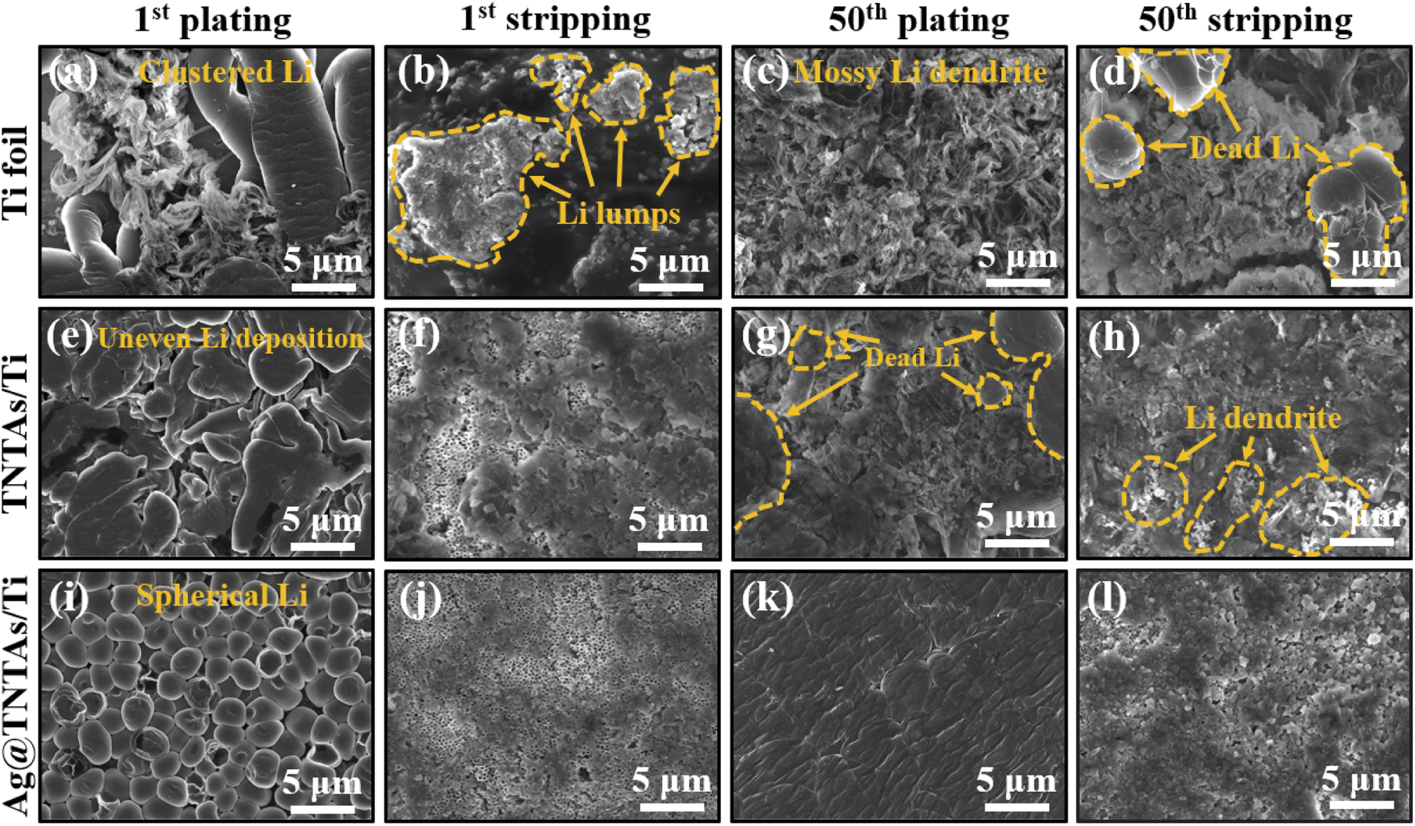 | ||
| Fig. 2 The deposited Li morphological evolution on (a–d) bare Ti foil, (e–h) TNTAs/Ti and (i–l) Ag@TNTAs/Ti current collectors at a current density of 1 mA cm−2 and cycling capacity of 1 mA h cm−2 at the 1st and 50th cycle. | ||
The Li deposition behaviors on Ti foil, TNTAs/Ti and Ag@TNTAs/Ti substrates with different capacities were further investigated, and the surface morphologies were observed using a SEM (Fig. S7†). When the area capacity was 0.2 mA h cm−2, smooth lithium deposition was achieved within the Ag@TNTAs/Ti framework without apparent lithium agglomeration. As seen from the fractures of TiO2 nanotubes in the cross-sectional SEM image of Ag@TNTAs (Fig. S8†), Ag nanoparticles decorated on the inner and outer walls of TiO2 nanotubes couldn't be observed owing to the covering of deposited Li over the nanotube surface. Besides, it's clear that the inner diameter of nanotubes obviously decreases while the outer diameter of nanotubes increases, which is attributed to the Li deposition onto the surface of TiO2 nanotubes. This demonstrates that during the initial deposition stage, lithium is preferentially deposited into the inner space of the Ag@TNTAs/Ti framework. In contrast, needle dendrites or/and lithium lumps were observed on the surface of Ti foil and TNTAs/Ti substrates. This manifests the uneven lithium deposition on the Ti foil and TNTAs/Ti, particularly the bare Ti foil. Upon increasing the capacity to 1 mA h cm−2, all top surfaces of Ti, TNTAs/Ti and Ag@TNTAs/Ti were fully covered by metallic lithium with uniform spherical lithium particles for Ag@TNTAs/Ti but visible dendritic lithium for Ti foil and TNTAs/Ti substrates. On further increasing the capacity of Li plating to 2 mA h cm−2, the metallic lithium (covered with SEI film) on the top surface of Ag@TNTAs/Ti is still flat, dense and uniform, whereas the initial uneven lithium deposition exacerbates the dendrite growth of lithium on the Ti foil and TNTAs/Ti. The above analysis shows that the 3D Ag@TNTAs/Ti framework can act as a redistributor for lithium ions, thus achieving stable and uniform Li deposition.
Further, DFT calculations were performed to compare the adsorption configuration and adsorption energy of Li atoms on the surface of TiO2 and Ag (Fig. S9†). The adsorption energies for Li@TiO2 and Li@Ag are −3.10 eV and −2.64 eV, which are attributed to the formation of Li–O and Li–Ag bonds. Actually, surface lithiation from TiO2 to the Li-rich Li0.5TiO2 phase and then to the Li-rich Li1TiO2 phase occurs during the first cycle,38,39 corresponding to the plateau around 1.7 V and the small inflection region around 1.4 V, and when the voltage drops steadily to the plateau voltage below 0 V, Li metal starts to deposit on the TNTAs/Ti surface (Fig. S10†). The adsorption energy for Li@Li0.5TiO2 has been reported to be slightly lower than that of Li@TiO2.40 This suggests that both TiO2 (Li0.5TiO2) and Ag are highly lithiophilic, and uniform nucleation and growth of Li metal over the Ag NP decorated TiO2 nanotube surface is readily achieved during Li plating.
According to the above analysis, the lithium plating/stripping behaviors on Ti foil, TNTAs/Ti and Ag@TNTAs/Ti substrates are schematically illustrated in Fig. 3. On the Ti foil surface, tiny Li nucleation sites occur at the electrode/electrolyte interface due to the non-uniformity of the metal surface, particularly the bump points, sharp edges and curved areas. The nucleation tips gather electric charges, which increases the local current density and also leads to accumulation of surrounding Li-ions on the nucleation tips.41 Li rigorously grows on the sharp tips, resulting in the formation of Li dendrites as illustrated in Fig. 3a. By comparison, ordered and spaced TNTAs with a large surface area and inner space could reduce the local electroplating current density and provide confined space to accommodate lithium deposition, and the lithiophilic surface of TiO2 may greatly reduce the overpotential for lithium plating. Nevertheless, the poor electrical conductivity of TiO2 (band gap of ∼3.2 eV) may lead to sluggish reaction kinetics, and the higher Li-ion concentration in the upper area of TNTAs enables faster deposition of lithium on the top of TNTAs, thus soon blocking nanotubular structures and causing subsequent dendrite formation due to the uncontrolled Li growth without special confinement as shown in Fig. 3b. When employing the 3D Ag@TNTAs/Ti framework for hosting Li deposition, Li nucleation and growth is enabled by the lithiophilic Ag nanoseeds on the surface of TNTAs, and the highly conductive Ag NPs can also significantly improve the conductivity of the electrode and promote uniform distribution of current density throughout the nanotubular walls.40 Such a 3D Ag@TNTAs/Ti scaffold with favorable electrical conductivity, tubular structure, large surface area, and abundant lithiophilic sites effectively regulates the Li deposition behavior and achieve uniform and reversible Li deposition, thereby avoiding Li dendrite formation (Fig. 3c).
 | ||
| Fig. 3 Schematic illustration of Li electrochemical deposition behaviors on (a) bare Ti, (b) TNTAs/Ti and (c) Ag@TNTAs/Ti substrates. | ||
The nucleation overpotential is described as the variation between the sharp dip voltage and the stable platform voltage during the initial stage of Li deposition, reflecting the energy barrier of heterogeneous nucleation for Li deposition and closely related to the lithiophilic properties of the substrates.42,43 The larger the nucleation overpotential, the higher the difficulty for Li deposition. The influence of the 3D TNTAs and Ag nanoseeds on Li nucleation and deposition was assessed by comparing the nucleation overpotentials of Li deposition onto different substrates at 1 mA cm−2 (Fig. 4a and b). The nucleation overpotential for Li deposition onto the Ti substrate is up to 60 mV, whereas the Li nucleation overpotential on TNTAs/Ti is obviously lower, about 44 mV. When employing the 3D Ag@TNTAs/Ti substrate for Li deposition, the nucleation overpotential is even lower, about 28 mV. This result clearly proves that nanotubular structured TNTAs modified with lithiophilic Ag NPs significantly lower the Li nucleation barrier and achieve uniform Li deposition. The CE, the ratio of Li stripping capacity to the Li plating capacity, is critical to evaluate the cyclability and safety of Li metal batteries. Severe dendritic growth generally corresponds to a lower cycling CE and vice versa.44 The CEs of Li plating/stripping on different substrates at various current densities and capacities were compared, as shown in Fig. 4c. At a current density of 1 mA cm−2 and cycling capacity of 1 mA h cm−2, the CE of the Ti|Li half-cell suffers obvious fluctuations after 100 cycles due to the dendritic Li growth. What's worse, the Li dendrite growth will lead to the break of the surface SEI layer and exposure of fresh Li to the electrolyte, aggravating the side reactions and lowering down the CE. The TNTAs/Ti|Li cell retains a CE around 97.6% for 250 cycles. By contrast, the Ag@TNTAs/Ti|Li cell operates steadily for 1000 cycles with a CE of over 98.5%, benefiting from homogeneous Li nucleation and deposition onto the Ag@TNTAs/Ti substrate. When cycled at a higher current density of 2 mA cm−2 and a capacity of 2 mA h cm−2 (Fig. 4d), the Ag@TNTAs/Ti|Li cell still shows superior cycling stability with a CE of over 97% for more than 250 cycles. Furthermore, EIS analysis for the symmetric cells under open circuit potential also manifests the superior interface stability of the Ag@TNTAs/Ti|Li cell in comparison to that of the Ti|Li, TNTAs/Ti|Li cells. After cyclic Li plating/striping at 1 mA cm−2 with 1 mA h cm−2 for 50 cycles, the Ag@TNTAs/Ti|Li symmetric cell shows the lowest interfacial charge transfer resistance (9.6 Ω), much lower than that of TNTAs/Ti|Li (34.7 Ω) and Ti|Li cells (73.1 Ω), demonstrating a stable electrode/electrolyte interface as well as fast electron and ion transport on the electrode surface within the Ag@TNTAs/Ti|Li cell (Fig. S11, S12 and Table S1†).
 | ||
| Fig. 4 Voltage profiles during initial Li deposition onto the Ti foil, TNTAs/Ti and Ag@TNTAs/Ti substrates at 1 mA cm−2 for 1 mA h cm−2 (a and b). Comparison of the coulombic efficiencies of half cells with Ti foil, TNTAs/Ti and Ag@TNTAs/Ti as the working electrodes when cycled at (c) 1 mA cm−2 with a cycling capacity of 1 mA h cm−2 and (d) 2 mA cm−2 with a cycling capacity of 2 mA h cm−2. | ||
To assess the robustness of the as-constructed Ag@TNTAs/Ti–Li electrode, electrochemical measurements were conducted using a symmetric cell system. As observed in Fig. 5a, under a current density of 1 mA cm−2 with a charging capacity of 1 mA h cm−2, the Ti–Li|Li cell displays the highest cycling overpotential with a large hysteresis (106 mV), and suffers from severe overpotential fluctuation from 160 h, and soon short-circuits, mainly as a result of Li dendrite formation. By comparison, the TNTAs/Ti–Li|Li cell exhibits a much lower voltage hysteresis (62 mV), and its overpotential starts to increase rapidly from 600 h – that is, failure to work. The Ag@TNTAs/Ti–Li|Li cell shows the highest cycling stability with a low hysteresis within 40 mV over an ultralong cycling period of 2600 h. When cycled at a high current density of 5 mA cm−2 with a high capacity of 5 mA h cm−2, the Ag@TNTAs/Ti–Li|Li cell still maintains a low voltage polarization of around 100 mV, much lower than that of Ti–Li|Li and TNTAs/Ti–Li|Li counterparts, whose overpotentials respectively reach 650 and 320 mV. Additionally, the Ag@TNTAs/Ti–Li|Li cell also achieves a long lifespan with a stable voltage profile over 500 h, whereas Ti–Li|Li and TNTAs/Ti–Li|Li cannot operate steadily and short-circuit occurs at 60 h and 120 h. The rate performance of the three symmetric cells at current densities of 0.5, 1, 2 and 5 mA cm−2 with a fixed capacity of 1 mA h cm−2 was further measured. The average hysteresis of Ag@TNTAs/Ti–Li|Li is 22, 40, 56 and 140 mV at the current densities of 0.5, 1, 2 and 5 mA cm−2, much lower than those of Ti–Li|Li and TNTAs/Ti–Li|Li cells at the same current density. Such extraordinary performance of the Ag@TNTAs/Ti–Li anode is attributed to the remarkably suppressed lithium dendrite formation and the stable SEI film benefitting from the elaborate structural and compositional design of the Ag@TNTAs/Ti scaffold for uniform Li plating/stripping.
 | ||
| Fig. 5 Voltage profiles of the Ti foil, TNTAs/Ti and Ag@TNTAs/Ti electrodes in symmetric cells at (a) 1 mA cm−2 with a capacity of 1 mA h cm−2 and (b) 5 mA cm−2 with a capacity of 5 mA h cm−2. (c) Rate capability of Ti–Li|Li, TNTAs/Ti–Li|Li and Ag@TNTAs/Ti–Li|Li symmetric cells measured at current densities from 0.5 to 5 mA cm−2 with a fixed capacity of 1 mA h cm−2. | ||
To validate the application potential of the Ag@TNTAs/Ti–Li anode in the real battery system, Li|LFP, TNTAs/Ti–Li|LFP and Ag@TNTAs/Ti–Li|LFP full cells were assembled and tested. As shown in Fig. 6a, the Ag@TNTAs/Ti–Li|LFP cell delivers an initial reversible capacity of 155.2 mA h g−1 at 0.5C and retains 77.9% capacity with an average CE of ≈99.7% over 200 cycles, showing great robustness. By contrast, Li|LFP and TNTAs/Ti–Li|LFP full cells can't work steadily with capacity suddenly dropping to zero after 30 cycles and 85 cycles respectively. The charge/discharge voltage profiles of the different cells at the 1st and 20th cycle are shown as Fig. 6b and c. As observed, the Ag@TNTAs/Ti–Li|LFP cell shows the lowest voltage polarization during cycling. Ag@TNTAs/Ti–Li|LFP also displays commendable rate performance (Fig. 6d). Even at a high rate of 2C, the Ag@TNTAs/Ti–Li|LFP cell still achieves a discharge capacity of 108.6 mA h g−1, obviously higher than that of Li|LFP and TNTAs/Ti–Li|LFP. These prominent performances of the Ag@TNTAs/Ti–Li electrode demonstrate its great potential for application in high-energy Li metal batteries.
 | ||
| Fig. 6 Electrochemical performances of Li|LFP, TNTAs/Ti–Li|LFP and AgTNTAs/Ti–Li|LFP cells: (a) cycling stability at 0.5C, charge/discharge profiles at 0.5C for (b) the 1st cycle and (c) the 20th cycle, and (d) rate capability at various rates from 0.1 to 2C. | ||
4 Conclusions
In summary, well-aligned and spaced TiO2 nanotube arrays were grown on Ti foil and surface decorated with ultrafine Ag nanocrystals (Ag@TNTAs/Ti) by anodization combined with an impregnation approach. Such 3D architecture was employed as a confined space host for Li metal deposition. First, uniform TiO2 nanotubular structures with a large surface allow fast electron/ion transport and uniform local current density distribution, leading to homogeneous Li growth on the nanotube surface. Second, Ag nanocrystals and TiO2 nanotubes have good lithium affinity, which facilitates Li+ capture and reduces Li nucleation barrier, enabling uniform nucleation and growth of Li metal over the 3D Ag@TNTAs/Ti scaffold. Third, such a 3D host confines Li plating within nanotubular structures to restrain volume expansion associated with Li plating/stripping. As a consequence, the Ag@TNTAs/Ti electrode exhibits a dendrite-free plating morphology and operates steadily for 1000 cycles with a CE of over 98.5% at a current density of 1 mA cm−2 and cycling capacity of 1 mA h cm−2. Remarkably, the Ag@TNTAs/Ti–Li electrode shows a much lower hysteresis of 40 mV over an ultralong cycle period of 2600 h at 1 mA cm−2 with a cycling capacity of 1 mA h cm−2 in symmetric cells. Moreover, the full cells with the Ag@TNTAs/Ti–Li anode and LiFePO4 cathode achieve a high capacity of 155.2 mA h g−1 at 0.5C and retains 77.9% capacity with an average CE of ≈99.7% over 200 cycles. This work may provide new guidelines for design and construction of 3D-host-based stable and dendrite-free Li anodes for high-energy batteries.Author contributions
Yulei Li and Shenhao Li contributed equally to this work. This manuscript was written through contributions of all authors. All authors have given approval to the final version of the manuscript.Conflicts of interest
There are no conflicts to declare.Acknowledgements
This research was financially supported by the National Natural Science Foundation of China (U1810204, 51972093, 52072104, and U1910210), Key Research and Development Plan of Anhui Province (202004b11020024), Nature Science Foundation of Anhui Province (2008085ME129), and Fundamental Research Funds for the Central Universities of China (PA2021GDSK0087, PA2020GDSK0088, PA2020GDJQ0026).References
- X. W. Gao, Y. N. Zhou, D. Z. Han, J. Q. Zhou, D. Z. Zhou, W. Tang and J. B. Goodenough, Joule, 2020, 4, 1864–1879 CrossRef CAS.
- K. Q. Qin, K. Holguin, M. Mohammadiroudbari, J. H. Huang, E. Y. S. Kim, R. Hall and C. Luo, Adv. Funct. Mater., 2021, 31, 2009694 CrossRef CAS.
- X. R. Chen, B. C. Zhao, C. Yan and Q. Zhang, Adv. Mater., 2021, 33, 2004128 CrossRef CAS PubMed.
- G. Yasin, M. Arif, T. Mehtab, X. Lu, D. L. Yu, N. Muhammad, M. T. Nazir and H. H. Song, Energy Storage Mater., 2020, 25, 644–678 CrossRef.
- X. Zhang, Y. A. Yang and Z. Zhou, Chem. Soc. Rev., 2020, 49, 3040–3071 RSC.
- Y. Y. Han, B. Liu, Z. Xiao, W. K. Zhang, X. L. Wang, G. X. Pan, Y. Xia, X. H. Xia and J. P. Tu, InfoMat, 2021, 3, 155–174 CrossRef CAS.
- D. H. Liu, Z. Y. Bai, M. Li, A. P. Yu, D. Luo, W. W. Liu, L. Yang, J. Lu, K. Amine and Z. W. Chen, Chem. Soc. Rev., 2020, 49, 5407–5445 RSC.
- Q. Wang, H. C. Wang, J. Y. Wu, M. Y. Zhou, W. Liu and H. H. Zhou, Nano Energy, 2021, 80, 105516 CrossRef CAS.
- R. H. Wang, W. S. Cui, F. L. Chu and F. X. Wu, J. Energy Chem., 2020, 48, 145–159 CrossRef.
- S. Chen, S. Y. Chen, D. J. Han, C. W. Bielawski and J. X. Geng, Chem.–Eur. J., 2022, 1–8, e202201580 Search PubMed.
- P. Shi, X. Q. Zhang, X. Shen, R. Zhang, H. Liu and Q. Zhang, Adv. Mater. Technol., 2020, 5, 1900806 CrossRef CAS.
- P. C. Zou, Y. M. Sui, H. C. Zhan, C. Y. Wang, H. L. Xin, H. M. Cheng, F. Y. Kang and C. Yang, Chem. Rev., 2021, 121, 5986–6056 CrossRef CAS PubMed.
- S. Park, H. J. Jin and Y. S. Yun, Adv. Mater., 2020, 32, 2002193 CrossRef CAS PubMed.
- J. Xiao, N. Xiao, C. Liu, H. Q. Li, X. Pan, X. Y. Zhang, J. P. Bai, Z. Guo, X. Q. Ma and J. S. Qiu, Small, 2020, 16, 2003827 CrossRef CAS PubMed.
- H. N. Lin, Z. W. Zhang, Y. D. Wang, X. L. Zhang, Z. X. Tie and Z. Jin, Adv. Funct. Mater., 2021, 31, 2102735 CrossRef CAS.
- C. P. Yang, Y. G. Yao, S. M. He, H. Xie, E. Hitz and L. B. Hu, Adv. Mater., 2017, 29, 1702714 CrossRef PubMed.
- M. S. Huang, Z. G. Yao, Q. F. Yang and C. L. Li, Angew. Chem., Int. Ed., 2021, 60, 14040–14050 CrossRef CAS PubMed.
- T. Y. Yang, L. Li, F. Wu and R. J. Chen, Adv. Funct. Mater., 2020, 30, 2002013 CrossRef CAS.
- S. Chen, K. J. Tao, X. Chen, Y. Q. Meng, M. Y. Wang, J. Zhou, C. Chen, Y. L. Wang, K. N. Hui, C. W. Bielawski and J. X. Geng, Chem.–Eur. J., 2021, 27, 15706–15715 CrossRef CAS PubMed.
- B. Moorthy, J. H. Kim, H. W. Lee and D. K. Kim, Energy Storage Mater., 2020, 24, 602–609 CrossRef.
- C. Z. Sun, A. M. Lin, W. W. Li, J. Jin, Y. Y. Sun, J. H. Yang and Z. Y. Wen, Adv. Energy Mater., 2020, 10, 1902989 CrossRef CAS.
- K. F. Wang, Q. Chen, Y. Y. Hu, W. Wei, S. Z. Wang, Q. Shen and P. Qu, Small, 2018, 14, 1802132 CrossRef PubMed.
- Y. Y. Feng, H. H. M. Rijnaarts, D. Yntema, Z. J. Gong, D. D. Dionysiou, Z. R. Cao, S. Y. Miao, Y. L. Chen, Y. Ye and Y. H. Wang, Water Res., 2020, 186, 116327 CrossRef CAS PubMed.
- A. Auer and J. Kunze-Liebhauser, Small Methods, 2019, 3, 1800385 CrossRef.
- L. L. Wu, W. W. Jiang, H. T. Zou, C. Z. Ye, J. Zhang, G. J. Xu, X. M. Li, Z. H. Yue, F. G. Sun and L. Zhou, J. Mater. Chem. A, 2021, 9, 20748–20757 RSC.
- Y. Mei, J. H. Zhou, Y. T. Hao, X. Hu, J. Lin, Y. X. Huang, L. Li, C. G. Feng, F. Wu and R. J. Chen, Adv. Funct. Mater., 2021, 31, 2106676 CrossRef CAS.
- J. Q. Liu, M. J. Dai, J. Wu, Y. Hu, Q. Zhang, J. W. Cui, Y. Wang, H. H. Tan and Y. C. Wu, Sci. Bull., 2018, 63, 194–202 CrossRef CAS.
- B. Delley, J. Chem. Phys., 1990, 92, 508–517 CrossRef CAS.
- B. Delley, J. Chem. Phys., 2000, 113, 7756–7764 CrossRef CAS.
- J. P. Perdew, K. Burke and M. Ernzerhof, Phys. Rev. Lett., 1996, 77, 3865–3868 CrossRef CAS PubMed.
- R. A. DiStasio, B. Santra, Z. F. Li, X. F. Wu and R. Car, J. Chem. Phys., 2014, 141, 084502 CrossRef PubMed.
- Y. Inada and H. Orita, J. Comput. Chem., 2008, 29, 225–232 CrossRef CAS PubMed.
- H. J. Monkhorst and J. D. Pack, Phys. Rev. B: Solid State, 1976, 13, 5188–5192 CrossRef.
- S. Q. Wu, X. Y. Li, Y. Q. Tian, Y. Lin and Y. H. Hu, Chem. Eng. J., 2021, 406, 126747 CrossRef CAS.
- W. G. Wang, M. Wu, P. Han, Y. Liu, L. He, Q. H. Huang, J. Wang, W. S. Yan, L. J. Fu and Y. P. Wu, ACS Appl. Mater. Interfaces, 2019, 11, 3061–3069 CrossRef CAS PubMed.
- D. Yan, C. Yu, X. Zhang, J. Li, J. Li, T. Lu and L. Pan, Electrochim. Acta, 2017, 254, 130–139 CrossRef CAS.
- F. Guo, C. Wu, H. Chen, F. Zhong, X. Ai, H. Yang and J. Qian, Energy Storage Mater., 2020, 24, 635–643 CrossRef.
- G. Calcagno, A. Lotsari, A. Dang, S. Lindberg, A. E. C. Palmqvist, A. Matic and C. Cavallo, Mater. Today Energy, 2020, 16, 100424 CrossRef.
- M. H. Zhang, K. B. Yin, Z. D. Hood, Z. H. Bi, C. A. Bridges, S. Dai, Y. S. Meng, M. P. Paranthaman and M. F. Chi, J. Mater. Chem. A, 2017, 5, 20651–20657 RSC.
- Y. Z. Lu, J. S. Wang, Y. Chen, X. Y. Zheng, H. R. Yao, S. Mathur and Z. S. Hong, Adv. Funct. Mater., 2021, 31, 2009605 CrossRef CAS.
- A. X. Wang, Q. B. Deng, L. J. Deng, X. Z. Guan and J. Y. Luo, Adv. Funct. Mater., 2019, 29, 1902630 CrossRef.
- S. Wu, Z. Zhang, M. Lan, S. Yang, J. Cheng, J. Cai, J. Shen, Y. Zhu, K. Zhang and W. Zhang, Adv. Mater., 2018, 30, 1705830 CrossRef PubMed.
- Y. Zhao, L. Wang, J. Zou, Q. Ran, L. Li, P. Chen, H. Yu, J. Gao and X. Niu, J. Energy Chem., 2022, 65, 666–673 CrossRef.
- P. B. Zhai, L. X. Liu, X. K. Gu, T. S. Wang and Y. J. Gong, Adv. Energy Mater., 2020, 10, 2001257 CrossRef CAS.
Footnote |
| † Electronic supplementary information (ESI) available. See https://doi.org/10.1039/d2na00526c |
| This journal is © The Royal Society of Chemistry 2022 |