
 Open Access Article
 This Open Access Article is licensed under a
 Creative Commons Attribution 3.0 Unported Licence
Pt nanoparticles under oxidizing conditions – implications of particle size, adsorption sites and oxygen coverage on stability†
Asfaw G.
Yohannes‡
 ab,
Karin
Fink
a and
Ivan
Kondov
*b
ab,
Karin
Fink
a and
Ivan
Kondov
*b
aInstitute of Nanotechnology, Karlsruhe Institute of Technology, Hermann-von-Helmholtz-Platz 1, 76344 Eggenstein-Leopoldshafen, Germany
bSteinbuch Centre for Computing, Karlsruhe Institute of Technology, Hermann-von-Helmholtz-Platz 1, 76344 Eggenstein-Leopoldshafen, Germany. E-mail: ivan.kondov@kit.edu
First published on 13th September 2022
Abstract
Platinum nanoparticles are efficient catalysts for different reactions, such as oxidation of carbon and nitrogen monoxides. Adsorption and interaction of oxygen with the nanoparticle surface, taking place under reaction conditions, determine not only the catalytic efficiency but also the stability of the nanoparticles against oxidation. In this study, platinum nanoparticles in oxygen environment are investigated by systematic screening of initial nanoparticle–oxygen configurations and employing density functional theory and a thermodynamics-based approach. The structures formed at low oxygen coverages are described by adsorption of atomic oxygen on the nanoparticles whereas at high coverages oxide-like species are formed. The relative stability of adsorption configurations at different oxygen coverages, including the phase of fully oxidized nanoparticles, is investigated by constructing p–T phase diagrams for the studied systems.
1 Introduction
Transition metals, such as platinum (Pt), are widely known for their catalytic performance in both oxidizing and reducing reactions and have been widely applied industrially for hydrocarbon oxidation,1 for abatement of automobile exhaust gases,2,3 in fuel cells4 and in catalytic reforming.5 The use of metallic nanoparticles as catalysts is motivated not only by their large active surface area but also by their special catalytic properties due to their particular size, shape and structure. For catalyst design, control over these latter variables implies the ability to manipulate the catalytic activity by introducing specific facets, edges and corners in the structure of the nanoparticles, which is essential for optimizing the activity and selectivity.6Many industrially relevant catalytic reactions, relying on late transition metals as catalysts, often proceed in oxygen-rich operating conditions or involve oxygen as a reacting species on the surface of a metal catalyst. Acquiring a fundamental understanding of the nature of the interaction between metal surfaces and oxygen is key to explain the role of oxygen in a number of important catalytic chemical processes.7 Metal–oxygen interactions are manifested in the formation of different metal–oxygen surface states, such as surface-adsorbed atomic oxygen, surface oxide films, and even bulk metal oxides, for many metallic catalysts.7 Thereby atomic and molecular oxygen adsorption is regarded as oxygen activation for subsequent oxidation reactions on the catalyst surface and the reactivity of the catalyst is often represented as a function of the oxygen adsorbate coverage. A modeling study of small nanoparticles of different metals has shown that oxygen activation is enhanced substantially at active sites with low coordination numbers8 that raises the question about the stability of these sites against oxidation. Dissociation of molecular oxygen on the truncated octahedron platinum nanoparticles with 38, 79 and 116 atoms9,10 has been investigated using density functional theory (DFT) whereby it has been shown that barrierless oxygen dissociation occurs on the (111) facet accompanied by significant surface distortion. A preference for the edge bridge sites for atomic oxygen adsorption and an increase of the adsorption energy with atomic oxygen coverage have been found in a DFT study of cuboctahedral nanoparticles with 55, 147 and 309 atoms.11 Adsorption energy of atomic oxygen enters different scaling relations that, in combination with microkinetic modeling, enable prediction of the rates of various catalytic reactions12 involving this species.
When oxygen interacts with a metal surface, different oxide films can be formed depending on the partial pressure, temperature, and orientation of the metal surface. Numerous experimental and DFT studies have characterized oxide formation on different Pt surfaces,13–18 on the Pd(111)![[thin space (1/6-em)]](https://www.rsc.org/images/entities/char_2009.gif) 18–20 and the Cu(111) surface.21 Pressure–temperature phase diagrams have been constructed for the extended Cu(111)–O21 and Pt(111)–O15 surface systems based on DFT data, as well as for extended Pd surfaces and Pd nanoparticles by using molecular dynamics.22 In all these studies surface oxide formation has been considered.15,21,22
18–20 and the Cu(111) surface.21 Pressure–temperature phase diagrams have been constructed for the extended Cu(111)–O21 and Pt(111)–O15 surface systems based on DFT data, as well as for extended Pd surfaces and Pd nanoparticles by using molecular dynamics.22 In all these studies surface oxide formation has been considered.15,21,22
CO oxidation on the surface of small Pt nanoparticles is known to accompany oscillatory behavior under realistic conditions and results in a change of the catalytic activity.23,24 This phenomenon would have consequences for the exhaust gas catalysis.25,26 Some of the hypotheses to explain this oscillatory behavior suggest cyclic oxidation-reduction24,27 and reversible surface phase transitions of Pt surfaces.28 There has been disagreement concerning whether the surface or subsurface Pt oxides are active.18,29–32 For example, Boubnov et al.23 have found that low-coordinated surface Pt sites on small Pt nanoparticles (nm) are oxidized at temperatures higher than 135 °C and become inactive for the CO oxidation.
A comprehensive ab initio study of adsorption of atomic oxygen will be therefore very useful to scrutinize these hypotheses by giving more insight and understanding of the oxygen–nanoparticle interactions. The produced data will enable the construction of phase diagrams of relevant Pt nanoparticles in oxygen environment to find the most stable oxygen adsorption configurations under experimental conditions and the limits of stability against formation of Pt oxide nanoparticles. To this end, we employ DFT to study atomic oxygen adsorption on four different Pt nanoparticles addressing all possible adsorption sites. To investigate the effect of oxygen coverage on the nanoparticles, after screening configurations with different occupied adsorption sites for different numbers of adsorbed oxygen atoms, we compute the oxygen adsorption energy. We determine how the adsorption energy depends on nanoparticle size, type and coordination number of the occupied adsorption sites and oxygen coverage. Using an approximation of the free energy based on the adsorption energies computed by DFT,33,34 we construct the p–T phase diagrams for all four nanoparticles. The phase diagrams allow us to examine the most stable adsorption configurations with varying the pressure and temperature and to find the conditions for which the metallic nanoparticles are not oxidized. In addition, structural reorganization of surface Pt atoms under increasing oxygen coverage will be detected and discussed.
2 Methods
The computations and data analyses in this work have been performed using FireWorks35 and the Atomic Simulation Environment (ASE).362.1 Structural models and DFT calculations
All DFT calculations have been performed using the Vienna ab initio simulation package (VASP) code37,38 with spin polarization. The core electrons have been described by using projector augmented wave (PAW) potentials.39 The wave functions (orbitals) of the valence electrons have been expanded using plane waves with an energy cutoff of 450 eV. The Perdew–Burke–Ernzerhof (PBE)40 generalized gradient approximation has been used to describe the exchange-correlation functional. The latter has been widely used for metallic systems21,41,42 including platinum nanoparticles. We expect that all adsorption energies will become somewhat higher when using the RPBE43 or PBE-vdW.44 However, the focus of this study is on the relative stability of the adsorbed species rather than on providing high-accuracy reference data or accuracy assessment of different charge density functionals.The initial nanoparticle structures have been constructed from bulk fcc Pt with the experimental lattice constant of 3.92 Å corresponding to a nearest-neighbor distance of 2.77 Å. To be able to use the plane-wave VASP code for non-periodic Pt nanoparticles, the latter have been modelled in cubic cells with three-dimensional periodic boundary conditions. To ensure that the interactions between neighboring periodic images are negligible, a vacuum region along each of the three directions has been added so that the distance between two nearest surface atoms in neighboring images is at least 16 Å. The first Brillouin zone has been sampled by the gamma point only. Unconstrained geometry optimizations have been performed using the conjugate gradient algorithm until the maximum force on any atom was below 0.01 eV Å−1 and the electronic relaxation has been converged within 10−6 eV. The first-order Methfessel–Paxton smearing method45 with smearing width of 0.2 eV has been used.
For the adsorption energies discussed in Sections 3.1 and 3.2, the O2 energy has been calculated with the same DFT parameters outlined above. The O2 energy used in the free–energy diagrams in Section 3.3 has been corrected to compensate for the strongly overestimated O2 binding energy using a GGA density functional that has been reported e.g. in ref. 21 and in the references therein. First, the O2 dissociation energy has been calculated using the “hard” PAW pseudopotential with a kinetic energy cutoff of 900 eV and a Gaussian smearing parameter of 0.005 eV. Then, the zero-point energy (787.380 cm−1)46 has been subtracted from the experimental dissociation energy (493.687 kJ mol−1).47 Finally, the correction is found as the difference of the DFT-calculated O2 dissociation energy and the experimental O2 dissociation energy. The correction to the O2 energy obtained is 0.460 eV per atom that is in good agreement with the difference of 0.48 eV per atom reported in a similar DFT study.21
The Pt slabs, used in Section 3.1 to model the (111) and (100) extended surfaces on fcc Pt, have been constructed from bulk fcc Pt with a lattice constant of 3.92 Å by including three Pt layers in all space directions, i.e. using a 3 × 3 supercell. In the z direction, that is perpendicular to the slab surface, a vacuum layer of 12 Å has been included to both the top and the bottom slab surfaces. The adsorbed oxygen atoms have been added to the top layer in z direction. The positions of the atoms in the bottom layer in z direction have been kept fixed during relaxation performed using a Monkhorst–Pack k-point grid with (5, 5, 1) divisions. A similar slab model has been used elsewhere.48–50
Different PtO2 nanoparticles have been constructed from the most stable β-PtO2 bulk structure (orthorhombic, space group Pnnm)51 following this procedure: (1) repeat the atoms in the primitive cell along all cell vectors; (2) remove Pt and O atoms that are the most distant from the structure centroid and have the lowest coordination numbers so that the number of dangling bonds is minimized and the stoichiometry of PtO2 is maintained; (3) repeat step (2) until the target size is reached. By varying the parameters of the algorithm several different nanoparticles for each size have been obtained. The structures of these nanoparticles have been fully relaxed using Gaussian smearing of 0.05 eV until the difference between the energies of two subsequent ionic relaxation steps was less than 10−4 eV per Pt atom and the largest norm of the forces acting on the nuclei after the last ionic relaxation step was 0.05 eV Å−1. For each nanoparticle size the structure with the lowest total energy has been selected and its total energy has been used in the phase diagrams in Section 3.3. It is noted that we have not performed global optimization but a local relaxation of several different nanoparticles of the same size. The relaxed structures of the lowest-energy PtO2 nanoparticles are available in the ESI.†
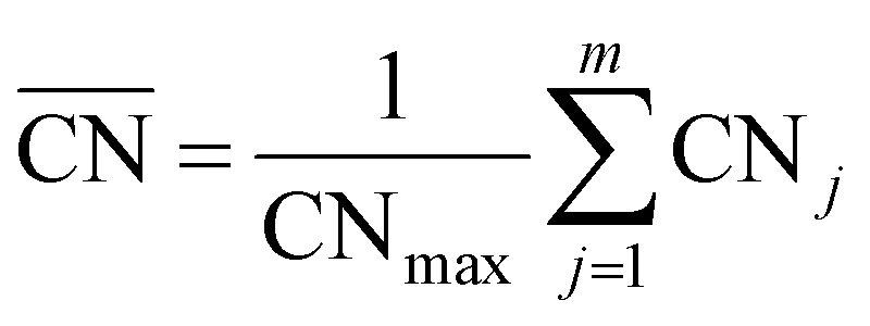
The generalized coordination number52,53 has been used to describe the various individual adsorption sites on the Pt nanoparticle surface. The generalized coordination number  of a surface site with m unique nearest neighbors is defined as:
 | (1) |
2.2 Calculating the adsorption energy and adsorption free energy
The adsorption energy of a single adsorbed oxygen atom on a Ptn nanoparticle is defined as: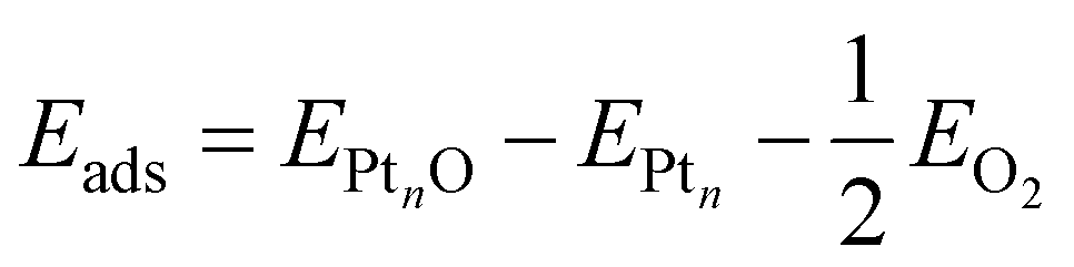 | (2) |
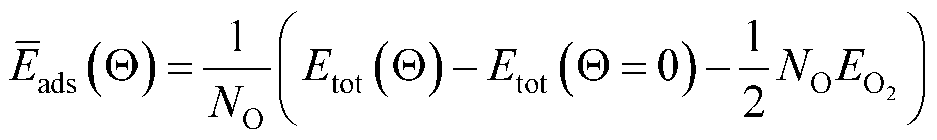 | (3) |
When metal surfaces are exposed to oxygen, various structures can be formed depending on the partial pressure of oxygen and on the temperature, such as surface adsorbed oxygen, surface oxide films or bulk metal oxides.21,54,55Ab initio atomistic thermodynamics approach is applied to determine the effect of temperature (T) and pressure (p) on various surface-adsorbate structures under realistic experimental conditions.21,54,55 Using this approach, the most stable surface structure is determined at given temperature and oxygen partial pressure in the surrounding gas phase that enables the construction of a p–T phase diagram containing the stable regions of different phases.21 In this approach, the Gibbs free energy of adsorption ΔGads(Θ, T, p) is defined in the equation:
| ΔGads(Θ, T, p) = G(Θ, T, p) − G(Θ = 0, T, p) − NOμO(T, p) | (4) |
| ΔGads(Θ, T, p) ≈ NO(Ēads(Θ) − μO(T, p) | (5) |
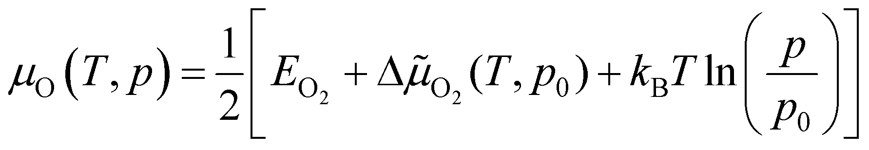
The chemical potential of gas-phase oxygen μO(T, p) can be expressed as a function of temperature and pressure using the formula21,54,55
 | (6) |
![[small mu, Greek, tilde]](https://www.rsc.org/images/entities/char_e0e0.gif) O2(T, p) includes the contributions from vibrations and rotations of O2, as well as the ideal gas entropy at standard pressure, and EO2 is the electronic internal energy of the O2 molecule as calculated using DFT. The function ΔO2(T, p0) has been tabulated for temperatures in the range from 100 to 2000 K by using the Shomate equations with parameters based on experimental data56 (data provided in the ESI†).
O2(T, p) includes the contributions from vibrations and rotations of O2, as well as the ideal gas entropy at standard pressure, and EO2 is the electronic internal energy of the O2 molecule as calculated using DFT. The function ΔO2(T, p0) has been tabulated for temperatures in the range from 100 to 2000 K by using the Shomate equations with parameters based on experimental data56 (data provided in the ESI†).
3 Results
Platinum nanoparticles of sizes in the range of 1–10 nm have been employed as catalysts in experimental studies.23,57,58 Some studies have found that a particle size within the average size of 2 nm is optimal for high catalyst activity.57–59 On the other hand, truncated and cuboctahedron nanoparticles, that comprise both (111) and (100) facets in addition to edges and corners, show catalytic activity superior to regular octahedron and cubic nanoparticles.41 Several studies, for example,7,9,53,60 have been carried out on truncated octahedron nanoparticles. Therefore, we chose truncated octahedron nanoparticles Pt38, Pt79, Pt116 and Pt201 (shown in Fig. 1) with sizes in the 1–2 nm range.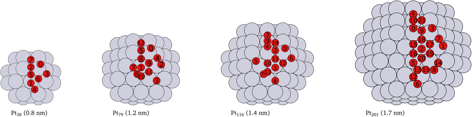 | ||
| Fig. 1 Cartoons of the structures of the studied nanoparticles. The size for every nanoparticle, shown in brackets, is defined as the longest inter-atomic distance. The platinum atoms are shown in gray color and the red circles indicate the locations of adsorbed oxygen atoms and the indices of the adsorption sites used in Tables 1, 2, 3 and 4. Multiply occurring sites are shown only once. | ||
3.1 Adsorption of single oxygen atoms
First, we consider single oxygen atoms adsorbed on the nanoparticles at all possible adsorption sites. This information allows us to determine the most preferred sites in the limit of low coverage and is needed for the screening in Section 3.2 to select lowest-energy configurations for adsorption at higher coverage.The adsorption energies calculated using eqn (2) are summarized in Tables 1, 2, 3 and 4. Additionally, we have visualized the same data in Fig. 2. Because of the very complex behavior of the adsorption energy with variation of system size, facet/surface, site type and site location, we present the data also statistically in Fig. 2 and in Table 5. By computing the correlation coefficients (r2), we test how good different linear regression models for the adsorption energy as a function of site coordination numbers fit the available data. We choose a linear regression model assuming that the dependence of the adsorption energy on the coordination numbers is linear. This approach is well established for small adsorbate species, including atomic oxygen, on Pt nanoparticles.52,53 A small r2 means that the a linear model does not well fit the data whereas a large r2 implies (statistically) a good linear relationship.
 and total number of sites (Ns) of the given index
| # | Site type | Site location | CN |
|
E ads (eV) | N s |
|---|---|---|---|---|---|---|
| 5 | hcp | Corner | 11 | 4.09 | −1.69 | 24 |
| 2 | Bridge | Edge 111–100 | 8 | 3.50 | −1.61 | 24 |
| 6 | fcc | Corner | 10 | 3.68 | −1.58 | 24 |
| 7 | Trough | Corner | 9 | 2.77 | −1.27 | 6 |
| 3 | Bridge | Edge 111–111 | 8 | 3.67 | −1.23 | 12 |
| 0 | Ontop | Corner | 6 | 4.00 | −1.03 | 24 |
| 1 | Ontop | Terrace 111 | 9 | 6.00 | −0.47 | 8 |
| 4 | Bridge | Terrace 111 | 10 | 4.50 | Unstable | 48 |

 and total number of sites (Ns) of the given index
| # | Site type | Site location | CN |
|
E ads (eV) | N s |
|---|---|---|---|---|---|---|
| 5 | Bridge | Edge 111–100 | 8 | 3.61 | −1.48 | 24 |
| 4 | Bridge | Edge 111–111 | 9 | 4.33 | −1.47 | 24 |
| 9 | fcc | Corner | 11 | 4.41 | −1.40 | 48 |
| 10 | fcc | Terrace | 15 | 5.86 | −1.40 | 8 |
| 8 | hcp | Edge 111–100 | 11 | 4.45 | −1.34 | 24 |
| 12 | Trough | Corner | 9 | 2.92 | −1.32 | 6 |
| 11 | hcp | Edge 111–111 | 14 | 5.68 | −1.22 | 24 |
| 0 | Ontop | Corner | 6 | 4.08 | −0.92 | 24 |
| 2 | Ontop | Edge 111–111 | 7 | 5.00 | −0.43 | 12 |
| 1 | Ontop | Terrace 111 | 9 | 6.67 | −0.12 | 24 |
| 3 | Bridge | Terrace 111 | 10 | 4.94 | Unstable | 48 |
| 6 | Bridge | Terrace 111 | 13 | 6.33 | Unstable | 24 |
| 7 | Bridge | Terrace 111 | 11 | 5.39 | Unstable | 48 |

 and total number of sites (Ns) of the given index
| # | Site type | Site location | CN |
|
E ads (eV) | N s |
|---|---|---|---|---|---|---|
| 4 | Bridge | Edge 111–100 | 9 | 4.33 | −1.63 | 48 |
| 6 | Bridge | Edge 111–111 | 8 | 3.89 | −1.49 | 12 |
| 14 | Trough | Corner | 13 | 4.46 | −1.40 | 24 |
| 12 | fcc | Corner | 10 | 4.14 | −1.39 | 24 |
| 9 | Bridge | Terrace 100 | 11 | 5.50 | −1.33 | 72 |
| 11 | hcp | Corner | 12 | 4.95 | −1.24 | 48 |
| 10 | fcc | Edge 111–100 | 13 | 5.23 | −1.23 | 24 |
| 13 | hcp | Terrace | 16 | 6.41 | −1.01 | 8 |
| 0 | Ontop | Corner | 6 | 4.17 | −0.87 | 24 |
| 2 | Ontop | Edge 111–100 | 7 | 5.17 | −0.56 | 24 |
| 3 | Ontop | Terrace 100 | 8 | 6.33 | −0.25 | 6 |
| 1 | Ontop | Terrace 111 | 9 | 6.67 | Unstable | 24 |
| 5 | Bridge | Terrace 111 | 10 | 5.00 | Unstable | 48 |
| 7 | Bridge | Terrace 111 | 13 | 6.33 | Unstable | 24 |
| 8 | Bridge | Terrace 111 | 11 | 5.50 | Unstable | 72 |

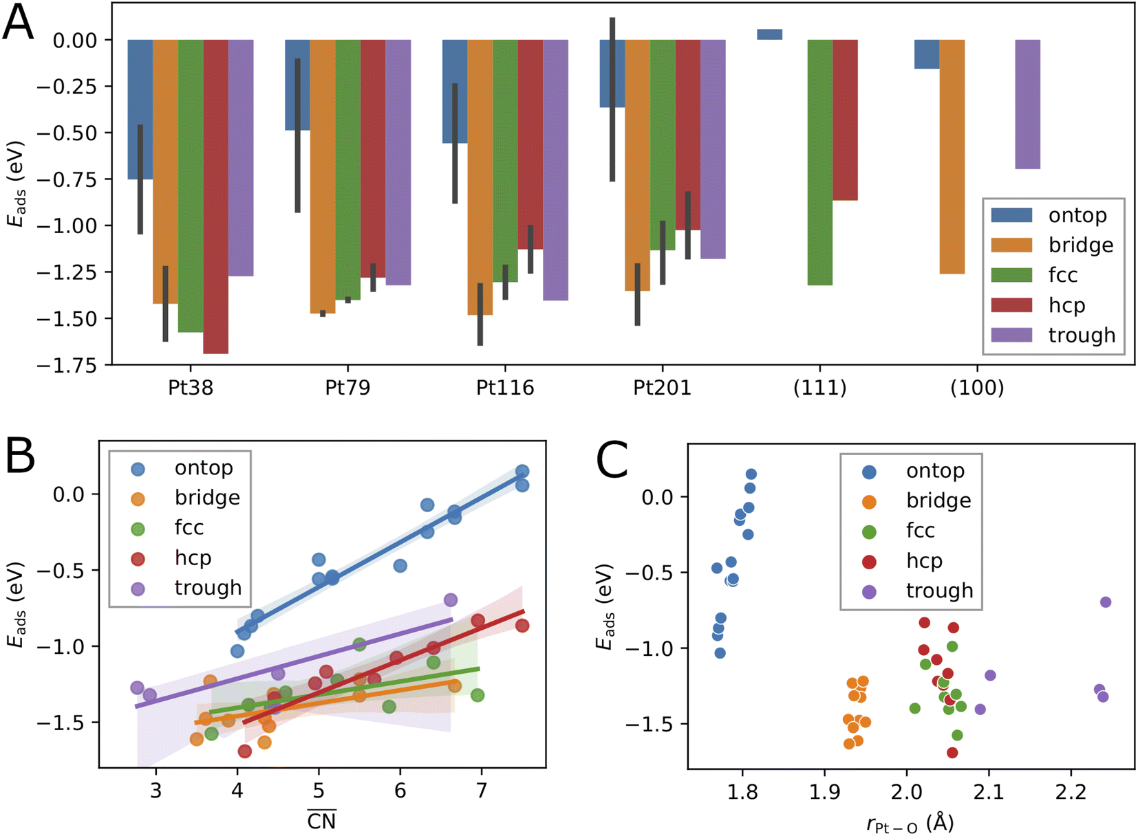 | ||
Fig. 2 Correlation between the calculated adsorption energy Eads and the system size (A), the generalized coordination number  (B), and the average Pt–O bond length rPt–O (C), for single oxygen atoms adsorbed at sites of different type. The black vertical bars denote minimum and maximum values. (B), and the average Pt–O bond length rPt–O (C), for single oxygen atoms adsorbed at sites of different type. The black vertical bars denote minimum and maximum values. | ||
3.1.1 Effects of the nanoparticle size and the adsorption site type
The variation of the adsorption energy with system size is shown in Fig. 2A. The ontop site adsorption energy is the highest compared to other sites that is also found for ontop adsorption on the extended (111) and (100) surfaces. On average, the adsorption energy increases with nanoparticle size and, with the exception of the Pt116 nanoparticle, approaches the adsorption energy at ontop sites on the extended surfaces. The correlation coefficient for a linear regression model is only 0.12 (see Table 5). Adsorption of O atoms at corner ontop sites is stable for all nanoparticle sizes and the adsorption energy is increasing monotonously. In contrast, ontop adsorption on the (111) terrace is stable with increasing energy on the smaller Pt38 and Pt79 nanoparticles while unstable on the large Pt116 and Pt201 nanoparticles. The latter is very similar to the ontop terrace adsorption on the extended (111) surface with the same CN = 9 and = 7.5. Similarly to (111) terrace ontop adsorption, the adsorption energy at (100) terrace ontop site is increasing for Pt116 and Pt201 but is always lower than on the extended (100) surface.
For all nanoparticles, the adsorption at bridge sites on the (111) terrace is unstable with no exception. During a structural relaxation starting with an oxygen atom at such bridge sites, the oxygen atom migrates to a nearby three-fold hollow site (fcc or hcp). The same behavior is found for the bridge adsorption on the extended (111) surface. In contrast, bridge site adsorption at any locations other than the (111) terrace is the most stable on Pt79, Pt116 and Pt201. Bridge adsorption at edge sites is found particularly stable that agrees with the findings in previous DFT studies of oxygen on truncated octahedron nanoparticles.7,9,10,60 A similar site preference has been found for cuboctahedron nanoparticles.11 Only on the smallest Pt38, the adsorption at three-fold hollow sites is the most stable that is again in agreement with previous DFT studies.7,9 On average, the adsorption energy at bridge sites changes with nanoparticle size only slightly with no pronounced direction of change, that is described by the very low correlation coefficient of only 0.06. A similar behavior is found for the adsorption energy at four-fold hollow (trough) sites on the (100) facet. A linear regression analysis reveals a very slight increase of Eads with nanoparticle size with a correlation coefficient of 0.22. In contrast, at fcc and hcp sites, Eads strongly increases on average with nanoparticle size with correlation coefficients 0.72 and 0.60, respectively.
Adsorption energies on three-fold hollow sites (fcc and hcp) also exhibit large variations with the site locations. Adsorption on sites at corner locations is always more stable than at terrace and edge locations (see Tables 2, 3 and 4), while no regular preference between terrace and edge locations can be found. The energy differences are relatively small but, due to the large number of sites, the overall effect on the adsorption energy at high oxygen coverage can be very large. On the Pt38 nanoparticle, the hcp adsorption mode is the most stable followed by the fcc adsorption mode. The three-fold hollow site adsorption becomes less stable than the bridge site adsorption on Pt79, Pt116 and Pt201, and than the trough site adsorption on Pt116 and Pt201. On average, the adsorption energy at fcc and hcp sites strictly increases with nanoparticle size. The Eads increase is weaker at fcc sites and stronger at hcp sites, as shown in Fig. 2A. This is in contrast to Eads variation at bridge, ontop and trough sites where only a slight change with almost no trend can be found. Considering the comparable number of hollow sites and bridge sites at edge locations, we expect that the bridge and trough sites will more likely contribute to the most stable configurations at high oxygen coverage than the three-fold hollow sites.
 and total number of sites (Ns) of the given index
| # | Site type | Site location | CN |
|
E ads (eV) | N s |
|---|---|---|---|---|---|---|
| 9 | Bridge | Edge 111–100 | 9 | 4.39 | −1.53 | 48 |
| 7 | Bridge | Edge 111–111 | 9 | 4.44 | −1.31 | 24 |
| 17 | fcc | Corner | 11 | 4.59 | −1.31 | 48 |
| 10 | Bridge | Terrace 100 | 11 | 5.50 | −1.22 | 24 |
| 21 | Trough | Corner | 13 | 4.50 | −1.18 | 24 |
| 18 | hcp | Corner | 12 | 5.09 | −1.17 | 48 |
| 20 | fcc | Terrace | 15 | 6.41 | −1.11 | 24 |
| 19 | hcp | Edge 111–111 | 14 | 5.95 | −1.08 | 24 |
| 15 | fcc | Edge 111–100 | 13 | 5.50 | −0.99 | 24 |
| 16 | hcp | Terrace | 16 | 6.95 | −0.83 | 24 |
| 3 | Ontop | Corner | 6 | 4.25 | −0.80 | 24 |
| 0 | Ontop | Edge 111–111 | 7 | 5.00 | −0.56 | 12 |
| 1 | Ontop | Edge 111–100 | 7 | 5.17 | −0.54 | 24 |
| 4 | Ontop | Terrace 100 | 8 | 6.33 | −0.07 | 6 |
| 5 | Ontop | Terrace 111 | 9 | 7.50 | 0.15 | 8 |
| 2 | Ontop | Terrace 111 | 9 | 6.92 | Unstable | 48 |
| 6 | Bridge | Terrace 111 | 11 | 5.56 | Unstable | 48 |
| 8 | Bridge | Terrace 111 | 11 | 5.67 | Unstable | 48 |
| 11 | Bridge | Terrace 111 | 13 | 6.67 | Unstable | 48 |
| 12 | Bridge | Terrace 111 | 13 | 6.67 | Unstable | 48 |
| 13 | Bridge | Terrace 111 | 13 | 6.94 | Unstable | 48 |
| 14 | Bridge | Terrace 111 | 10 | 5.17 | Unstable | 48 |

Adsorption at trough sites has a peculiarity that we briefly discuss here. In the smaller Pt38 and Pt79 nanoparticles, where the single trough site is located in the middle of the 100 facet, the distance from the adsorbed oxygen atom to all four Pt atoms of the site is the same, 2.235 Å and 2.239 Å, respectively. In the larger Pt116 and Pt201 nanoparticles, the four trough sites are located at the corners of the 100 facet. On these two nanoparticles the distances from the adsorbed oxygen atom to the site atoms are different, e.g. Pt116 the distances are 1.997 Å to the corner atom, 2.970 Å to the terrace atom, and 2.136 Å to the edge atoms. Very similar, on the Pt201 nanoparticle the distances are 2.017 Å to the corner atom, 2.917 Å to the terrace atom, and 2.144 Å to the edge atoms. Therefore, the average adsorption bond lengths on Pt116 and Pt201 for trough sites are by about 0.1 Å shorter than on the extended surface and on Pt38 and Pt79, as it is shown in Fig. 2C.
3.1.2 Effect of the local environment
While, on average, the adsorption energy of single oxygen atoms increases with nanoparticle size, the variation for the same site type with nanoparticle size is more noticeable. In the previous subsection, it has been shown that adsorption energies on sites at different locations can strongly vary. This is because the number of nearest neighbors of the site atoms (CN), as well as the average coordination number of the nearest neighbors of the site atoms, i.e. the generalized coordination number ,52 depend on the specific location of the site of a given type. Therefore, in Fig. 2B, we consider here
  as a structural descriptor and investigate its relation to the computed adsorption energy. The same relationship has been studied for oxygen and other adsorbate species on Pt201 nanoparticles and extended Pt surfaces.52
Plotting the generalized coordination number against the adsorption energies yields a very good linear relation suggesting a decrease of binding energy of the oxygen adsorbate to the adsorption site, i.e. increase of adsorption energy, with the generalized coordination number for all different site types. A particularly high correlation coefficient 0.94 is obtained for the ontop site adsorption. The same correlation coefficient has been found for OH adsorption on different Pt nanoparticles.52 Using the conventional coordination number CN results in significantly lower correlation coefficient of 0.80 that is similar to the finding in ref. 52. In Table 5, the correlation coefficients found for the linear models with nanoparticle size, CN and  as descriptors are summarized. While the correlation of Eads with nanoparticle size is very weak, it is much stronger with CN, particularly when the data is grouped according to site types. When all data is included in the linear fit, the CN descriptor exhibits a poor correlation with correlation coefficient r2 = 0.06. A better correlation is obtained with
  for all sites except for the bridge sites where the correlation is of the same quality as with CN. When all data is included in the fit, the correlation coefficient is 0.39, i.e.
 is a more reliable descriptor for oxygen adsorption than CN. The thus defined linear regression model predicts lower adsorption energy for lower
  . However, the uncertainty in Eads prediction by using
  alone is very large without using the site type as a second descriptor. As shown in Fig. 2B this uncertainty can be as large as 1 eV for
  in the range from 4 up to 7.5. In particular, adsorption energies at ontop sites are much higher than those at other site types with approximately the same
  . An estimate of Eads for adsorption on other nanoparticles can be more reliable if both
  and site type are determined. Fig. 2C shows that the adsorption energy does not correlate with the average Pt–O bond length as it has been found previously for O adsorption on Pt201.60 In contrast, the bond length correlates well with site type with very small variations owing to nanoparticle size effects and site locations. As shown in Fig. 2C, the average bond length can be used to determine ontop, bridge and hollow site types with high certainty.
 , and and the cluster size, for sites of different types. Adsorption on extended Pt surfaces is not considered in the relation with cluster size
| Site type | Size | CN |
|
|---|---|---|---|
| Ontop | 0.12 | 0.80 | 0.94 |
| Bridge | 0.06 | 0.31 | 0.31 |
| fcc | 0.72 | 0.23 | 0.29 |
| hcp | 0.60 | 0.75 | 0.86 |
| Trough | 0.22 | 0.60 | 0.67 |
| All types | 0.08 | 0.06 | 0.39 |

3.2 Lowest-energy configurations with multiple oxygen adsorbates
In order to construct thermodynamic phase diagrams using eqn (5), it is important to find the most stable configurations with multiple adsorbed O atoms that are characterized by the lowest total adsorption energies per atom Ēads. Due to the extremely large number of possible configurations this is a nontrivial task. As a first approximation, we consider configurations that include the maximum number of adsorbates of every site type. For the maximum number of sites of a given type, see Tables 1, 2, 3 and 4. Next, we neglect the contributions of adsorption at sites with very high single-atom adsorption energies. We neglect all ontop adsorption modes and unstable bridge-site adsorption modes and consider all other site types. For example, for Pt38 this approximation yields 31 different configurations. Applying the same approximation to Pt201 results in 1023 configurations. This is why there should be additional systematic screening of the configurations in order to reduce the number of candidate structures that would be feasible for DFT. Using the adsorption energies of single adsorbates from the previous section we construct an energy score: | (7) |
| 〈1/r3〉 [Escore − min (Escore)] | (8) |
 | ||
| Fig. 3 Relation between the score energy Escore and the adsorption energy Ēads (A) and between Ēads − Escore and 〈1/r3ij〉 (B) for the Pt38 nanoparticle. (C) Change of the lowest adsorption energy Ēads and the lowest energy score Escore with oxygen coverage. The lowest coverage shown corresponds to single-oxygen adsorption for every nanoparticle. The symbols denote the data points and the lines are only added as a guide to the eye. | ||
Thus, after having performed calculations of all 35 configurations for Pt38, we calculated the adsorption energies of the first 50, 20 and 11 configurations for Pt79, Pt116 and Pt201, respectively, satisfying both criteria according to eqn (7) and (8). Additionally, for the larger nanoparticles, we added further adsorption configurations in that some site types are partially occupied and such that are not on the selection list but might be important considering their low adsorption energy of single O atoms. For example, the configuration on Pt201 with all 24 bridge sites (#7 in Fig. 1, CN = 9,  = 4.44) occupied by O atoms is only at positions 24 and 27 in the sorted criteria according to eqn (7) and (8), respectively. However, this is the second most stable adsorption mode for single O atoms on Pt201 (see Table 4). After extending the list, we have computed the adsorption energy for 64, 35 and 36 configurations on Pt79, Pt116 and Pt201, respectively. A full list of the considered configurations is provided in the ESI.†
For every nanoparticle size, we have grouped the configurations with equal number of O atoms, i.e. according to the oxygen coverage in monolayers (ML). From every group we have selected the configuration with the lowest total adsorption energy. The relevant data is summarized in Table 6.
| N Pt | N O | Θ | N c | Ē ads | 〈rPt–Pt〉s | 〈rPt–Pt〉 | 〈rPt–O〉 | 〈CNPt–Pt〉 | 〈CNPt–O〉 | N s/# | R[eqn (7)] | R[eqn (8)] |
|---|---|---|---|---|---|---|---|---|---|---|---|---|
| 38 | 1 | 0.03 | 7 | −1.69 | 2.68 | 2.73 | 2.06 | 7.4 | 0.1 | 1/5 | — | — |
| 38 | 6 | 0.19 | 1 | −1.36 | 2.67 | 2.75 | 2.25 | 7.6 | 0.6 | 6/7 | — | — |
| 38 | 8 | 0.25 | 2 | −1.69 | 2.75 | 2.71 | 2.06 | 6.3 | 0.6 | 8/5 | — | — |
| 38 | 12 | 0.38 | 1 | −1.42 | 2.74 | 2.75 | 1.95 | 7.6 | 0.6 | 12/3 | — | — |
| 38 | 16 | 0.50 | 2 | −1.49 | 2.82 | 2.78 | 2.05 | 6.3 | 1.3 | 16/5 | — | — |
| 38 | 18 | 0.56 | 1 | −1.18 | 2.84 | 2.82 | 2.02 | 7.6 | 1.3 | 6/7, 12/3 | — | — |
| 38 | 24 | 0.75 | 3 | −1.26 | 2.89 | 2.95 | 1.99 | 7.6 | 1.9 | 24/5 | — | — |
| 38 | 30 | 0.94 | 3 | −1.02 | 2.88 | 2.95 | 2.08 | 7.6 | 2.5 | 24/5, 6/7 | — | — |
| 79 | 1 | 0.02 | 10 | −1.48 | 2.70 | 2.75 | 1.94 | 8.5 | 0.0 | 1/5 | — | — |
| 79 | 6 | 0.10 | 1 | −1.18 | 2.70 | 2.75 | 2.25 | 8.5 | 0.3 | 6/12 | 37 | 1 |
| 79 | 8 | 0.13 | 2 | −1.40 | 2.72 | 2.77 | 2.04 | 8.5 | 0.3 | 8/9 | — | — |
| 79 | 14 | 0.23 | 1 | −1.07 | 2.71 | 2.80 | 2.12 | 8.5 | 0.6 | 8/10, 6/12 | 26 | 3 |
| 79 | 16 | 0.27 | 1 | −1.33 | 2.76 | 2.77 | 2.03 | 7.9 | 0.6 | 16/9 | — | — |
| 79 | 24 | 0.40 | 9 | −1.40 | 2.78 | 2.82 | 2.01 | 8.5 | 0.9 | 24/8 | 33 | 4 |
| 79 | 30 | 0.50 | 4 | −1.15 | 2.77 | 2.82 | 2.10 | 8.5 | 1.2 | 24/8, 6/12 | 36 | 6 |
| 79 | 32 | 0.53 | 4 | −1.17 | 2.80 | 2.81 | 1.97 | 8.5 | 0.9 | 24/4, 8/10 | 6 | 9 |
| 79 | 38 | 0.63 | 2 | −1.03 | 2.86 | 2.84 | 1.99 | 8.5 | 1.2 | 24/4, 8/10, 6/12 | 8 | 7 |
| 79 | 48 | 0.80 | 7 | −1.04 | 2.93 | 2.85 | 2.08 | 8.2 | 1.8 | 48/9 | 17 | 19 |
| 79 | 54 | 0.90 | 5 | −1.11 | 2.96 | 2.91 | 2.06 | 8.5 | 2.1 | 48/9, 6/12 | 23 | 16 |
| 79 | 56 | 0.93 | 4 | −0.97 | 2.88 | 2.86 | 2.01 | 8.5 | 1.8 | 24/4, 8/10, 24/8 | 16 | 15 |
| 116 | 1 | 0.01 | 11 | −1.63 | 2.72 | 2.75 | 1.93 | 8.9 | 0.0 | 1/4 | — | — |
| 116 | 8 | 0.10 | 1 | −1.04 | 2.73 | 2.79 | 2.01 | 8.9 | 0.2 | 8/13 | 38 | 2 |
| 116 | 12 | 0.15 | 1 | −1.47 | 2.74 | 2.76 | 1.95 | 8.9 | 0.2 | 12/6 | 9 | 1 |
| 116 | 20 | 0.26 | 1 | −1.07 | 2.75 | 2.77 | 2.00 | 8.9 | 0.4 | 12/6, 8/13 | 28 | 3 |
| 116 | 24 | 0.31 | 3 | −1.08 | 2.75 | 2.78 | 2.09 | 8.9 | 0.6 | 24/12 | 18 | 4 |
| 116 | 32 | 0.41 | 1 | −0.76 | 2.77 | 2.79 | 2.08 | 8.9 | 0.8 | 24/12, 8/13 | 32 | 9 |
| 116 | 36 | 0.46 | 2 | −1.02 | 2.81 | 2.79 | 2.09 | 8.9 | 0.8 | 12/6, 24/14 | 13 | 11 |
| 116 | 44 | 0.56 | 1 | −0.94 | 2.95 | 2.83 | 2.05 | 8.9 | 1.0 | 12/6, 24/14, 8/13 | 19 | 5 |
| 116 | 48 | 0.62 | 5 | −1.07 | 2.79 | 2.80 | 1.95 | 8.9 | 0.8 | 48/4 | 1 | 52 |
| 116 | 56 | 0.72 | 2 | −1.00 | 2.81 | 2.81 | 1.97 | 8.9 | 1.0 | 48/4, 8/13 | 4 | 37 |
| 116 | 60 | 0.77 | 3 | −0.94 | 2.88 | 2.86 | 2.03 | 8.9 | 1.4 | 12/6, 48/11 | 31 | 21 |
| 116 | 68 | 0.87 | 1 | −0.88 | 3.06 | 2.84 | 1.95 | 7.7 | 1.2 | 48/4, 12/6, 8/13 | 5 | 23 |
| 116 | 72 | 0.92 | 4 | −1.25 | 2.96 | 2.88 | 1.97 | 8.9 | 1.4 | 48/4, 24/12 | 3 | 25 |
| 201 | 1 | 0.01 | 15 | −1.53 | 2.72 | 2.77 | 1.93 | 9.4 | 0.0 | 1/9 | — | — |
| 201 | 24 | 0.20 | 3 | −1.23 | 2.76 | 2.78 | 1.94 | 9.4 | 0.2 | 24/7 | 24 | 27 |
| 201 | 48 | 0.39 | 8 | −1.28 | 2.81 | 2.81 | 2.00 | 9.4 | 0.6 | 24/17, 24/21 | — | — |
| 201 | 72 | 0.59 | 12 | −1.04 | 2.90 | 2.83 | 2.04 | 8.7 | 1.1 | 48/17, 24/21 | 55 | 11 |
| 201 | 88 | 0.72 | 1 | −1.08 | 2.91 | 2.85 | 2.02 | 9.4 | 1.2 | 48/17, 24/21, 8/20, 8/16 | — | — |
| 201 | 96 | 0.79 | 8 | −1.20 | 2.94 | 2.87 | 1.98 | 9.4 | 1.2 | 48/9, 48/17 | 4 | 58 |
| 201 | 120 | 0.98 | 4 | −1.11 | 2.99 | 2.87 | 2.00 | 9.1 | 1.6 | 48/9, 48/17, 24/20 | 11 | 48 |
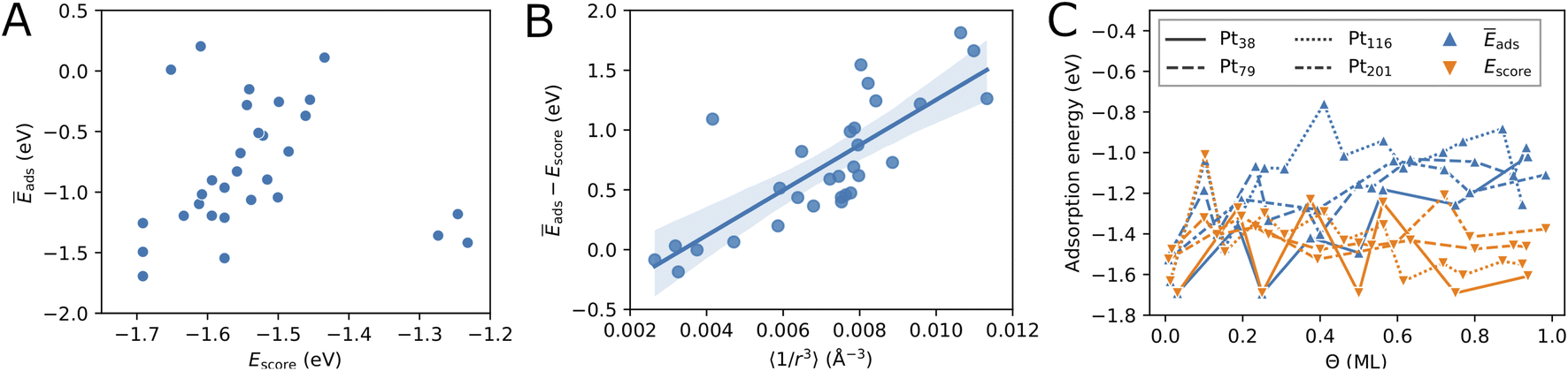
Fig. 3C compares the adsorption energy Ēads with the energy score Escore for increasing oxygen coverage Θ. Overall, the adsorption energy Ēads increases with oxygen coverage. Particularly, the adsorption energy of all configurations with Θ > 0.5 ML is higher than −1.3 eV per O atom. For single-atom adsorption, the adsorption energies vary between around −1.7 and −1.5 eV while at maximum coverage these vary from about −1.3 and −0.8 eV. A very similar increase of the adsorption energy with the coverage has been found in a DFT study of oxygen adsorption on cuboctahedral Pt55, Pt147, and Pt309 nanoparticles11 although the changes found here exhibit much stronger oscillations. In the same work,11 a quantity that is equivalent to Escore has been found to behave very similar on average, apart from the oscillations with increasing the coverage that are found here for O adsorption on truncated octahedral nanoparticles. Furthermore, the increasing difference between Escore and Ēads is in agreement with that found in ref. 11 and suggests that Escore provides (statistically) good estimates of the adsorption energy for low and moderate oxygen coverage.
Furthermore, in Fig. 3C we compare the adsorption energy to the energy score Escore that does not include effects such as electronic band effects due to bonding multiple oxygen atoms and the interactions between adsorbate atoms. At the lowest coverage, Escore coincides with Ēads. Then, in the low coverage range (Θ < 0.5 ML), Escore shows strong oscillations similar to Ēads and is relatively close to Ēads. In the high coverage range (Θ > 0.5 ML), Escore is substantially lower than Ēads. The higher adsorption energy can be explained with the effects of the large number of adsorbed atoms that are close to each other at high coverage. The energy score Escore does not include the latter effects and, therefore, does not change on average with the coverage, apart from the strong oscillations due to strongly different energies of the site types involved in the configurations. The increasing adsorption energy implies that configurations at high coverage will be stable only at sufficiently high oxygen chemical potential according to eqn (5).
After having introduced two screening criteria for the initially generated adsorbate configurations, one can naturally ask how successful the suggested selection criteria are by comparing the obtained lowest energy configurations. On average, in the cases of Pt79 and Pt116 the distance criterion is more successful for selecting low-coverage configurations, while the energy score criterion is more successful for selecting high-coverage configurations (see Table 6, last two columns). In the case Pt201 this also seems to be the case, though there are not many selected configurations in order to better support this finding. Overall, the distance criterion is more successful in selecting lowest-energy configurations on Pt79 than on Pt116. Five out of eleven lowest-energy configurations on Pt79 would have been missed if only the more simple energy score were used for screening. The Pt79 structures at 0.13 ML and 0.27 ML coverage and Pt201 structures at 0.39 ML and 0.72 ML coverage have been additionally considered due to their partial occupation, i.e. non-maximum possible Ns.
3.3 Phase diagrams
As introduced above, the Pt nanocatalyst has applications in the context of the CO oxidation reaction, whereby the operation temperature can vary up to 800 K. An important question is whether the whole nanoparticles or their surfaces get oxidized to PtO2 at high temperature, particularly at 600 K.18 Furthermore, most of the studies of CO oxidation have been carried out either in ultra high vacuum (UHV) at pressure 10−13 bar or at pressures around the standard pressure (1 bar).23,61 Therefore, we vary both the pressure in a very large range enclosing the UHV pressures, as well as the standard pressure and consider different temperatures in the range from 100 K to 1800 K.For every nanoparticle and oxygen coverage, we select the configuration with the lowest energy. Then using eqn (5) we compute the free energy as a function of the temperature and the O2 partial pressure. In Fig. 4, we show the computed adsorption free energy at Θ < 1 ML for the Pt38 nanoparticle as a function of the pressure at T = 600 K and as a function of the temperature at standard pressure (1 bar). Additionally, we have shown the free energy of the fully oxidized Pt38O76 nanoparticle that was calculated using eqn (3) by replacing the total energy Etot(Θ) of the nanoparticle–adsorbate complex with the total energy of the Pt38O76 nanoparticle and setting NO = 76.
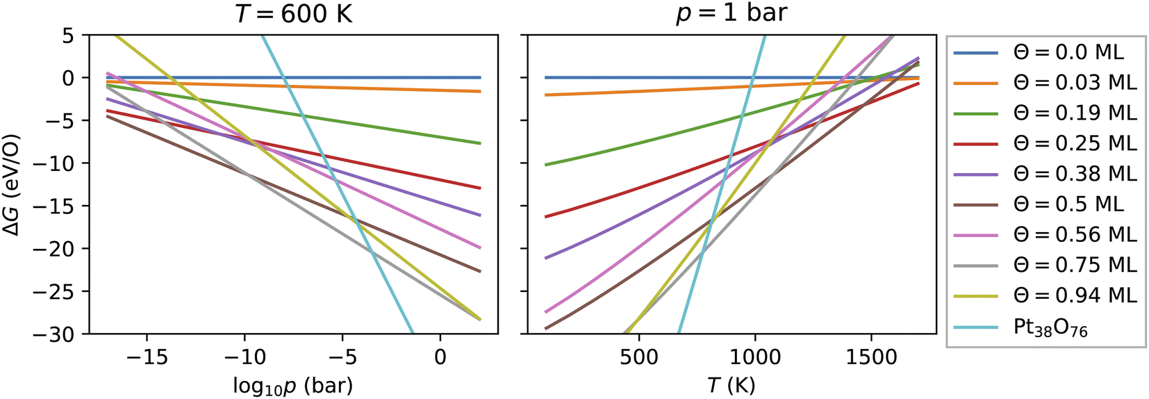 | ||
| Fig. 4 Adsorption free energy of all configurations with oxygen coverage below 1 ML on the Pt38 nanoparticle as a function of the pressure at T = 600 K and of the temperature at p = 1 bar. For comparison, the free energy of the fully oxidized nanoparticle Pt38O76 is shown. | ||
Here, we explain the reason to consider PtO2 nanoparticles as reference instead of the bulk PtO2 phase. Comparing oxygen adsorption energies on extended surfaces to bulk PtO2 energies is possible due to the infinite reservoir of bulk Pt atoms below the surface. Beyond a critical oxygen chemical potential, an infinitely large number of bulk Pt atoms would be oxidized to form bulk PtO2 that would give rise to a vertical line in Fig. 4 (a detailed discussion can be found in ref. 62). In contrast, in the case of Pt nanoparticles, the reservoir of bulk Pt atoms in every nanoparticle is finite that is manifested by a non-vertical line in Fig. 4 for the fully oxidized phase. The number of surface atoms will increase proportionally with increasing the number of bulk atoms via the number of nanoparticles. Particularly, the Pt and PtO2 nanoparticles are less stable than the corresponding bulk phases due to their large surface energy. Though this effect is known, we illustrate it in the ESI† based on the available data and show that all nanoparticles become more stable with increasing their size. On the other hand, under experimental conditions, no extended platinum oxide bulk phase but partially and fully oxidized Pt nanoparticles have been observed.23,27,58 Consequently, we use the nanoparticle free energies and not those of the bulk phase in the thermodynamic stability analysis.
3.3.1 Adsorption at low and moderate oxygen coverage
Fig. 4 shows that from the eight lowest-energy configurations on Pt38 shown in Table 6 only three are absolutely stable at oxygen coverage of 0.25, 0.50 and 0.75 ML. These three configurations involve only the hcp sites with the occupation of 8, 16, and 24 O atoms, respectively. At T = 600 K, only at extremely low pressures p ≲ 10−25 bar, the adsorbate-free Pt38 nanoparticle is the most stable phase and at pressures p ≳ 10−4 bar the oxide nanoparticles become the most stable phase. Under UHV conditions, the phase with 0.5 ML coverage is found stable. Similarly, at standard pressure, for T ≲ 780 K and T ≳ 1760 K, the Pt38O76 nanoparticle and the bare Pt38 nanoparticle, respectively, are the most stable phases. We note that other processes might take place in this high temperature range that are not considered in this study: (i) decomposition of PtO2 to PtO and O2; (ii) evaporation of the PtO2 nanoparticles to PtO2 gas.63–65 However, temperatures beyond 800 K are too high compared to the typical operational temperature range of Pt nanocatalysts and we are aiming to explain and predict Pt nanoparticle stability against oxidation within the experimental temperature range relevant for catalytic applications. In addition, the region on the phase diagram including the PtO and gaseous PtO2 phases would be only in a narrow range of pressures.64The computed p–T phase diagrams, shown in Fig. 5, include only the most stable phases. At standard pressure, the Pt79 nanoparticle is fully oxidized for temperatures above 800 K. The critical pressure for full oxidation of Pt79 at T = 600 K is p ∼ 10−4 bar. At standard pressure, the configuration at oxygen coverage of 0.9 ML is stable from ∼800 K up to ∼1150 K and under UHV conditions the same configuration is stable between 380 and 560 K. Between 560 and 770 K the configuration at coverage 0.4 ML is stable, followed by the configuration with one adsorbed oxygen atom at the (111)-(100) edge bridge site that is stable only up to 800 K after that the bare Pt79 nanoparticle becomes more stable.
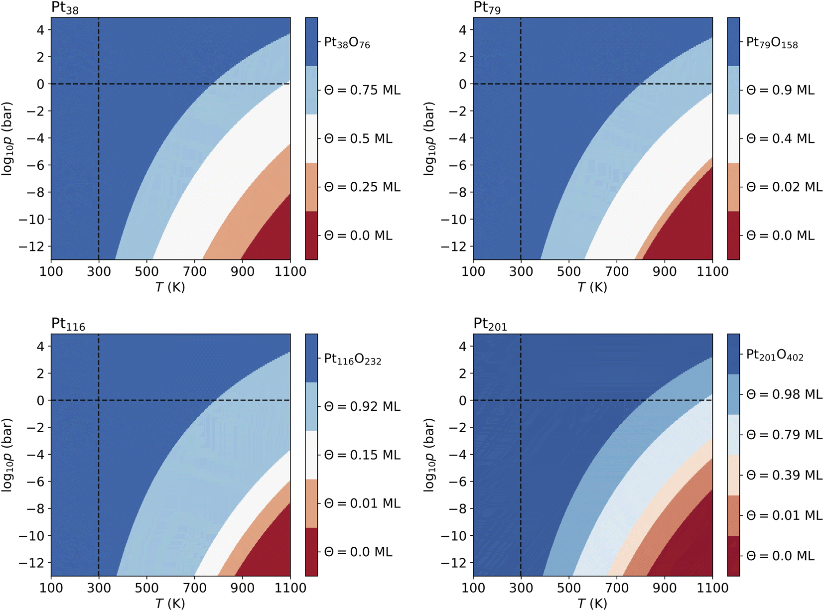 | ||
| Fig. 5 Phase diagrams displaying the most stable configurations with oxygen coverage up to 1 ML for the four nanoparticles. Standard temperature (T = 298.15 K) and standard pressure (p = 1 bar) are denoted by dashed lines. The pressure shown at the bottom of the diagrams corresponds to ultra high vacuum (UHV, p = 10−13 bar). | ||
On Pt116 the critical temperature of oxidation at standard pressure is ∼790 K which is very similar to the one found for Pt38 and Pt79. Again, the maximum pressure at 600 K for a stable metallic Pt116 oxygen-covered nanoparticle is ∼10−4 bar. In UHV the critical temperature is 380 K. The configurations with coverage of 0.92 ML is stable up to ∼700 K. The configuration with 0.15 ML coverage is stable between 700 and 800 K followed by the single-adsorbate complex up to 870 K. Adsorption at edge bridge sites dominates in all most stable configurations on Pt116, in contrast to Pt38 where only contributions of hcp adsorption modes, and to Pt79 where hcp, fcc and trough adsorption modes occur in the phase diagram.
On Pt201, the critical temperature of total oxidation at standard pressure is ∼820 K that is higher than any of the smaller nanoparticles. The maximal pressure for a non-oxidized Pt201 at 600 K is again ∼10−4 bar as has been found for all smaller nanoparticles. Four of the seven lowest-energy configurations occur in the phase diagram. Under UHV conditions, the configuration at coverage of 0.98 ML becomes stable for T ≳ 390 K. This configuration is stable for temperatures up to ∼512 K. At higher temperature, the configuration with coverage of 0.79 ML is formed and replaced only at ∼660 K by the configuration with Θ = 0.39 ML, followed by the complex with a single adsorbed oxygen atom (0.01 ML) occurring at 723 K that is stable up to 822 K. Notably, the two configurations at highest coverage of 0.79 and 0.98 ML combine (111)–(100) edge bridge and fcc adsorption modes while the configuration at moderate coverage of 0.39 ML combines corner fcc and trough adsorption modes.
3.3.2 Adsorption at high oxygen coverage
In the previous section, we have shown only data for coverage Θ ≤ 1 ML. Some of the selected configurations have oxygen coverage larger than 1 ML, i.e. the number of adsorbed oxygen atoms is larger than the number of surface atoms. The mean distance between the oxygen atoms is very small, however, some of these configurations are stabilized after a significant reorganization of the surface atoms and the adsorbed oxygen atoms during the structural relaxation. As we will show below, this reorganization does not only avoid the close initial distances between the adsorbed oxygen atoms but also leads to formation of an oxide layer on the surfaces of the nanoparticles.In order to better quantify the degree of reorganization and oxidation of the nanoparticles with increasing the oxygen coverage, we investigated the lowest-energy structures, shown in Fig. S2 in the ESI, in more detail.† The full information about the reorganization towards nanoparticle oxidation is contained in the radial distribution function for the Pt atoms (Pt–Pt pair correlation function) and for the Pt and O atoms (Pt–O pair correlation function). In the following, we restrict the analysis to the averaged nearest-neighbor distance between Pt atoms 〈rPt–Pt〉 and between Pt and O atoms 〈rPt–O〉, that is the most relevant quantity describing this effect. Additionally, we will use the averaged Pt–Pt and Pt–O coordination numbers 〈CNPt–Pt〉 and 〈CNPt–O〉, respectively, that indicate the average number of Pt and O nearest neighbors, respectively, of a central Pt atom. The nearest-neighbor distance and coordination number correspond respectively to the position and the integral of the first peak of the radial distribution function. These quantities are shown in Tables 6 and 7 for all lowest-energy adsorption configurations. For the sake of readability, we will omit the word “averaged” in the following.
| N Pt | N O | Θ | N c | Ē ads | 〈rPt–Pt〉s | 〈rPt–Pt〉 | 〈rPt–O〉 | 〈CNPt–Pt〉 | CNPt–O〉 | N s/# |
|---|---|---|---|---|---|---|---|---|---|---|
| 38 | 36 | 1.12 | 3 | −1.06 | 2.92 | 2.93 | 2.00 | 7.6 | 2.5 | 24/5, 12/3 |
| 38 | 42 | 1.31 | 3 | −1.04 | 2.99 | 3.00 | 2.04 | 7.6 | 3.2 | 24/5, 6/7, 12/3 |
| 38 | 48 | 1.50 | 3 | −1.20 | 3.17 | 3.06 | 1.98 | 6.3 | 3.2 | 24/5, 24/6 |
| 38 | 54 | 1.69 | 3 | −0.90 | 3.25 | 3.10 | 2.07 | 6.3 | 3.9 | 24/5, 24/6, 6/7 |
| 38 | 60 | 1.88 | 2 | −0.68 | 3.28 | 2.98 | 2.02 | 5.1 | 3.8 | 24/5, 24/6, 12/3 |
| 38 | 66 | 2.06 | 3 | −0.51 | 3.25 | 3.07 | 2.08 | 6.3 | 4.6 | 24/5, 24/6, 6/7, 12/3 |
| 79 | 62 | 1.03 | 2 | −1.00 | 2.99 | 2.92 | 2.06 | 8.2 | 2.4 | 48/9, 8/10, 6/12 |
| 79 | 72 | 1.20 | 7 | −1.22 | 3.12 | 2.92 | 1.99 | 6.7 | 2.4 | 24/5, 48/9 |
| 79 | 78 | 1.30 | 3 | −0.96 | 3.11 | 2.98 | 2.00 | 7.9 | 2.4 | 24/5, 48/9, 6/12 |
| 79 | 80 | 1.33 | 5 | −1.11 | 3.14 | 3.00 | 2.01 | 7.9 | 2.7 | 24/5, 48/9, 8/10 |
| 79 | 86 | 1.43 | 2 | −0.66 | 3.02 | 2.99 | 2.09 | 6.7 | 3.3 | 24/4, 8/10, 24/8, 6/12, 24/11 |
| 79 | 96 | 1.60 | 3 | −0.62 | 3.15 | 2.93 | 2.02 | 6.7 | 2.4 | 24/5, 48/9, 24/8 |
| 79 | 102 | 1.70 | 1 | −0.49 | 3.04 | 2.88 | 2.07 | 6.1 | 3.4 | 24/5, 24/4, 24/8, 6/12, 24/11 |
| 79 | 104 | 1.73 | 2 | −0.52 | 3.34 | 2.79 | 2.03 | 4.6 | 3.3 | 24/5, 24/4, 48/9, 8/10 |
| 79 | 128 | 2.13 | 1 | −0.12 | 2.98 | 2.87 | 1.96 | 7.3 | 1.5 | 24/5, 24/4, 48/9, 8/10, 24/8 |
| 116 | 80 | 1.03 | 2 | −1.13 | 2.97 | 2.88 | 1.99 | 8.9 | 1.7 | 48/4, 24/12, 8/13 |
| 116 | 84 | 1.08 | 2 | −0.96 | 3.07 | 2.94 | 2.04 | 8.5 | 2.1 | 12/6, 24/14, 48/11 |
| 116 | 92 | 1.18 | 1 | −0.88 | 3.09 | 2.98 | 2.04 | 8.9 | 2.3 | 12/6, 24/14, 48/11, 8/13 |
| 116 | 96 | 1.23 | 2 | −0.96 | 3.03 | 2.92 | 2.01 | 8.9 | 2.1 | 48/4, 24/12, 24/10 |
| 116 | 104 | 1.33 | 1 | −0.58 | 3.09 | 2.75 | 1.96 | 6.0 | 1.4 | 48/4, 48/11, 8/13 |
| 116 | 108 | 1.38 | 1 | −0.73 | 3.28 | 2.79 | 1.99 | 5.4 | 2.3 | 48/4, 12/6, 48/11 |
| 116 | 116 | 1.49 | 1 | −0.44 | 2.96 | 2.86 | 2.03 | 7.2 | 2.1 | 48/4, 12/6, 48/11, 8/13 |
First, we will consider the nearest-neighbor distances between surface Pt atoms 〈rPt–Pt〉s shown in Table 7. Their values vary from 2.92 Å to 3.34 Å for oxygen coverage from 1 up to 2 ML. For comparison, the nearest-neighbor distance in bulk fcc Pt, found in our DFT calculation, is 2.81 Å while in β-PtO2, the two nearest-neighbor Pt–Pt distances are 3.18 Å and 3.59 Å. The 〈rPt–Pt〉 distance in the Pt38, Pt79, Pt116 and Pt201 nanoparticles has been found 2.68 Å, 2.70 Å, 2.72 Å and 2.71 Å, respectively.
For Pt201 no configurations with Θ > 1 ML have been selected using the two criteria according to eqn (7) and (8). The screening process for the Pt116 nanoparticles yields several configurations with Θ > 1 ML and seven of them are shown in Table 7 but none of these configurations contributes to the phase diagram. However, in the case of Pt38 and Pt79, we have found lowest-energy configurations with Θ > 1 ML occurring in the phase diagram shown in Fig. 6.
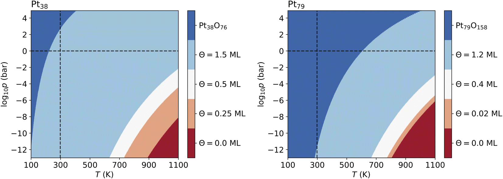 | ||
| Fig. 6 Phase diagrams showing the most stable configurations on Pt38 and Pt79 built with no restriction of oxygen coverage. Standard temperature (T = 298.15 K) and standard pressure (p = 1 bar) are denoted by dashed lines. The pressure shown at the bottom of the diagrams corresponds to ultra high vacuum (UHV, p = 10−13 bar). | ||
The lowest-energy configurations on Pt38 with oxygen coverage 1.12 and 1.31 do not show substantial reorganization of the nanoparticle indicating an oxidation that is evidenced by 〈rPt–Pt〉s below 3 Å. The configuration at Θ = 1.50 ML has the lowest absolute energy and appears prominently in the phase diagram (see Fig. 6A). This configuration has moderate degree of surface reorganization that is characterized by 〈rPt–Pt〉s Å. The configurations at coverage larger than 1.5 ML undergo a significant reorganization leading to oxidation of the corner platinum atoms. Characteristic for this reorganization are the high values of 〈rPt–Pt〉s that go beyond 3.25 Å.
The configuration at 1.03 ML on Pt79, with all fcc and trough sites occupied, exhibits a very weak reorganization of the surface Pt atoms, thus Pt79 preserves its characteristic shape. This is supported by the short nearest-neighbor distance between the surface Pt atoms (2.99 Å). The next lowest-energy configuration with 1.2 ML coverage, with 24 O atoms at (111)–(100) edge bridge sites and 48 O atoms at corner fcc sites is particularly stable and appears in the phase diagram (see Fig. 6B) although the initial average distance between the oxygen atoms is relatively short. The stabilization is due to a PtO2 oxide monolayer with a cage shape formed during structural relaxation involving all 36 Pt atoms from the twelve edges and the (100) facet (see Fig. S2 in the ESI†). The remaining 43 Pt atoms stay in a metallic Pt nanoparticle core enclosed in the oxide cage. For larger amounts of oxygen (>1.2 ML), no further stable phases can be found except for the fully oxidized Pt79O158 nanoparticle.
Overall, the degree of reorganization (oxidation) increases with oxygen coverage for all nanoparticles which is indicated by an increasing nearest-neighbor distance between the surface Pt atoms 〈rPt–Pt〉s in Tables 6 and 7 At coverage Θ < 0.5 ML, the nearest-neighbor distance is smaller than 3 Å in all considered configurations and nanoparticles. For Θ > 1 ML, the nearest-neighbor distance is larger than 3 Å in many configurations and larger than 2.8 Å in all configurations. The nearest-neighbor distance as a function of oxygen coverage is depicted in Fig. S3 in the ESI.†
4 Discussion
In the following we will compare the results to experimental X-ray photoelectron spectroscopy (XPS)66 and X-ray absorption spectroscopy (XAS) measurements58,67,68 on Pt nanoparticles.4.1 Oxidation state
Svintsitskiy et al.66 have studied platinum oxide nanoparticles of average size of 2.3 nm (this is the size of Pt201O402 in this work) prepared by discharge sputtering of a Pt electrode in an oxygen atmosphere. Using XPS, they have found that the Pt(IV) oxide nanoparticles are stable at room temperature in UHV. After heating to 275 °C (548 K) the oxide nanoparticles completely convert to Pt(0) nanoparticles going through Pt(II) oxide. This is in overall agreement with the computed phase diagrams in Fig. 5 and 6 except that the oxygen-free phase (bare Pt nanoparticles) sets on at significantly higher temperature (800 K). The most likely reason for the overestimated transition temperature in our study is the PBE density functional used that is known to overestimate the adsorbate binding energy69 thus making the phases at low oxygen coverage more stable.From XAS (EXAFS) spectra, Boubnov et al.58 have found O/Pt ratios between 0.32 and 0.90 for 1.2 nm and 2.1 nm Pt nanoparticles, depending on the oxidation state of the Pt nanoparticle. The highest O/Pt ratios of 0.66 and 0.90 after NO and CO oxidation reactions, respectively, have been found for the smallest 1.2 nm nanoparticle. The O/Pt ratio of 0.66 found after the NO oxidation reaction corresponds very closely (within 4%) to the phase with 0.90 ML coverage on the Pt79 nanoparticle that is most stable for coverage below 1 ML. The O/Pt ratio of 0.90 found after the CO oxidation reaction is very close (within 2%) to the one in the most stable phase at 1.20 ML coverage on the Pt79 nanoparticle. On the 2.1 nm nanoparticles, Boubnov et al.58 have found an O/Pt ratio of 0.32 after the CO oxidation reaction that does not correspond to any stable phase on the Pt201 nanoparticle (this corresponds to 0.52 ML oxygen on Pt201). It is noted that the 2.1 nm nanoparticle is considerably larger than Pt201 in this study that has a size of 1.7 nm.
4.2 Pt–Pt nearest-neighbor distances and coordination numbers
The Pt–Pt coordination numbers from EXAFS spectra58 found for the 1.2 nm nanoparticles are between 2 and 6 in the oxidized state and 7 and 9 in reduced metallic state, in agreement with our results. The Pt–Pt coordination number found here is 8.5 for the bare Pt79 nanoparticle and, with only few exceptions, for the phases for Θ < 1 ML (see Table 6). With increasing the oxygen coverage above 1 ML, the Pt–Pt coordination number decreases indicating smaller number of metallic bonds. For coverage larger than 1.20, the Pt–Pt coordination number is below 8 (see Table 7). For the most stable phase at 1.2 ML we find coordination number of 6.7. The coordination numbers between 2 and 6 found in ref. 58 must then correspond to more strongly oxidized nanoparticles than we have considered in this work. This is consistent with the Pt–Pt coordination number of 1.8 that we find in the fully relaxed PtO2 nanoparticle Pt79O158. This is somewhat smaller than the Pt–Pt coordination number (CN = 2) in the bulk β-PtO2 because in the bulk β-PtO2 every Pt atom has two nearest neighbors, both along the x-axis, whereas in the PtO2 nanoparticle some Pt atoms have only one nearest neighbor due the truncation. A similar decrease of the coordination numbers with the amount of adsorbed oxygen, starting with 8.9 for Θ = 0, is observed for the Pt116 nanoparticle.The Pt–Pt nearest-neighbor distances from EXAFS spectra58 have been found between 2.67 and 2.74 Å for 1.2 nm Pt nanoparticles depending on the oxidation state of the Pt nanoparticle. These small differences between the Pt–Pt nearest-neighbor distances in the reduced and oxidized phases are comparable to the experimental standard deviation error of 0.02 Å.58 In contrast, the Pt–Pt nearest-neighbor distance found in the Pt79 nanoparticle increases with oxygen coverage from 2.75 Å to 3.00 Å. As discussed above, this is due to reorganization of the surface Pt atoms towards oxide formation that is supported by the found 〈rPt–Pt〉s =3.12 Å in the phase at Θ = 1.2 ML corresponding to the Pt–Pt nearest-neighbor distance within Pt–O–Pt bridges in β-PtO2.67,68 For comparison, we have found a slightly larger 〈rPt–Pt〉s = 3.14 Å in the fully relaxed Pt79O158 nanoparticle that is only slightly smaller from 3.18 Å in the bulk β-PtO2.
In a study of electrochemical Pt oxidation in solution, Imai et al.67 have reported a Pt–Pt nearest-neighbor distance of 2.75 Å and coordination number of 9.5 for a 1.9 nm Pt nanoparticles. This is in agreement with the Pt–Pt nearest-neighbor distance of 2.77 Å and Pt–Pt coordination number of 9.4 found here in the largest Pt201 nanoparticle. The authors of ref. 67 have attributed the increased Pt–Pt nearest-neighbor distance of 3.1 Å to the formation of PtO2 oxides: α-PtO2 for oxygen coverage up to 1.5 ML and the more stable β-PtO2 at higher oxygen coverage.
4.3 Pt–O nearest-neighbor distances and coordination numbers
The Pt–O nearest-neighbor distance found varies from 1.93 up to 2.25 Å. In the low-coverage configurations, the Pt–O nearest-neighbor distance is determined by the type of adsorption modes included in the configuration and the number of adsorbate species pertinent to each mode. The different adsorption modes have very characteristic distances between the surface Pt atoms and the adsorbate oxygen atoms, as discussed in Section 3.1 and shown in Fig. 2C. In the configurations at high oxygen coverage, surface oxidation and reorganization of the surface Pt atoms occur and lead to Pt–O nearest-neighbor distances closer to those in the Pt oxides. A strong variation of Pt–O nearest-neighbor distance from 2.01 up to 2.19 Å58 and from 1.96 up to 1.99 Å68 has been found from EXAFS spectra. Imai et al.67 have found a gradual transition from longer Pt–O bonds (2.2 Å) due to adsorbed oxygen species into shorter Pt–O bonds in Pt oxides (2.0 Å) based on XAFS measurements.
As expected, the Pt–O coordination number in the lowest-energy configurations is close to zero at low oxygen coverage (Table 6). The Pt–O coordination number increases with the oxygen coverage, as seen in Tables 6 and 7 In the Pt38 nanoparticle, for oxygen coverage larger than 0.94 ML the Pt–O coordination number is larger than 2.5. At Θ = 2.06 ML the Pt–O coordination number is 4.6 that is very close to 4.8 found in the Pt38O76 nanoparticle (CN = 6 in bulk PtO2) indicating a strong oxidation and formation of oxide-like compound. In the larger nanoparticles, the Pt–O coordination number also increases with O coverage initially but the increase is slower. The maximum Pt–O coordination numbers found in Pt79, Pt116 and Pt201 are 3.4, 2.3 and 1.6, respectively. These coordination numbers deviate significantly from those in the Pt79O158, Pt116O232 and Pt201O402 nanoparticles, that are 5.0, 5.1 and 5.2, correspondingly.
For 1.2 nm nanoparticles after NO oxidation reaction a Pt–O nearest-neighbor distance of 2.01 Å and a Pt–O coordination number of 2.7 have been found.58 These are close to 2.06 Å and 2.1, respectively, for the most stable configuration of Pt79 at 0.90 ML oxygen coverage that has a very close O/Pt ratio. Similarly, for the nanoparticles of the same size after CO oxidation the Pt–O nearest-neighbor distance and coordination number found are 2.11 Å and 2.5, while the values determined for the 1.2 ML stable configuration on Pt79 are 1.99 Å and 2.4, respectively. Because the computed 0.90 ML and 1.2 ML phases also occur in the phase diagrams of Pt79 (see Fig. 5 and 6), this agreement with the experimental EXAFS data is notable.
It is noted, that the effects of CO and NO used in the experiments58 are not considered in this work. They may have influence on the most stable adsorption phase both due to interaction and entropy contributions. In addition, the sizes of the nanoparticles 0.9, 1.9, 2.1 and 3.0 nm studied experimentally58,67,68 are different from those of the model nanoparticle studied here except for the 1.2 nm nanoparticles58 that correspond to Pt79. Moreover, under in situ experimental conditions the system may not be in thermodynamic equilibrium. Other factors not considered in our model are the silica, titania and alumina supports58,68 and the metallic platinum support and solvent environment67 that may also influence the measured nanoparticle properties.
5 Conclusions
In this work, we have studied truncated octahedron platinum nanoparticles Pt38, Pt79, Pt116 and Pt201 exposed to oxygen using density functional theory. We have computed the adsorption energy for different amounts of adsorbed atomic oxygen on the nanoparticles considering all possible adsorption modes. In the case of single-atom adsorption, we have found that ontop adsorption is either unstable or has the highest adsorption energies compared to any other adsorption modes. Bridge adsorption at the (111) terrace sites is unstable without exceptions. The top-three most preferred adsorption sites are located at the edges and at the corners. Overall, we have found only weak correlation between adsorption energy and nanoparticle size as well as between the adsorption energy and coordination numbers (either generalized or the conventional). The latter correlation becomes more pronounced when the adsorption modes are considered separately. We find that the generalized coordination number provides a better description (based on a linear fit) for the adsorption energy than the conventional coordination number if every adsorption site type is taken separately.Considering all stable single-atom adsorptions and neglecting ontop adsorptions, we have generated all possible adsorption configurations at maximum occupancy and used two different screening criteria to further reduce the number of configurations. The distance criterion is more successful for selecting configurations at low coverage, whereas the energy criterion works better for configurations at high coverage. Due to the variance of the criteria, there may be still some statistical uncertainty that can be further reduced by increasing the number of output structures. Molecular dynamics or Monte Carlo sampling methods can be considered to replace the screening, especially for larger nanoparticles where the generation of the input structures for screening may become infeasible due to their extremely huge number. At each oxygen coverage between 0 and 2 ML, we have selected the lowest-energy configuration and constructed thermodynamic p–T phase diagrams for the four systems.
Overall, with increasing the amount of oxygen, we have observed stronger reorganization of the surface layer evidenced by the increasing nearest-neighbor distance between the surface Pt atoms. This reorganization leads to the formation of oxide-like surface compounds on Pt38 and Pt79 for Θ > 1 ML that are characterized by Pt–Pt and Pt–O nearest-neighbor distances and coordination numbers becoming closer to those in the corresponding PtO2 nanoparticles. Overall, the computed phase diagrams and the structural data is in good qualitative agreement with XPS and XAS experimental measurements. For example, the nanoparticles are fully oxidized at room temperature both at standard pressure and highly oxidized in ultrahigh vacuum, that is in agreement with the experimental findings. The computed structural data for Pt79, for which direct comparison has been possible, are in very good quantitative agreement with XAS structural characterization data. In particular, the degree of oxidation and structural data for the two most stable phases on Pt79 correspond to these found in experiments with 1.2 nm nanoparticles.
This study has focused on the stability of the nanoparticles–oxygen system with regard to thermochemical conditions. In future, the presented approach can be readily extended to study stability of the system in various electrochemical conditions, i.e. for the construction of Pourbaix diagrams.
Author contributions
Conceptualization, K. F.; data curation, A. G. Y. and I. K.; formal analysis, A. G. Y. and I. K.; funding acquisition, I. K. and K. F.; investigation, A. G. Y. and I. K.; methodology, A. G. Y., I. K. and K. F.; project administration, I. K. and K. F.; resources, I. K. and K. F.; software, A. G. Y. and I. K.; supervision, I. K. and K. F.; validation, I. K. and K. F.; visualization, A. G. Y. and I. K.; writing – original draft, A. G. Y. and I. K.; writing – review & editing, A. G. Y., I. K. and K. F.Conflicts of interest
There are no conflicts to declare.Acknowledgements
This work has been performed on the supercomputer ForHLR funded by the Ministry of Science, Research and the Arts Baden-Württemberg and by the Federal Ministry of Education and Research. KF thanks for support by the CRC 1441 ‘TrackAct’. We acknowledge support by the KIT-Publication Fund of the Karlsruhe Institute of Technology.References
- M. N. Marei, H. A. Khan, J. A. Badra, A. Montoya, A. Farooq and A. R. Masri, Energy Fuels, 2022, 36, 2044–2057 CrossRef CAS.
- C. Huang, W. Shan, Z. Lian, Y. Zhang and H. He, Catal. Sci. Technol., 2020, 10, 6407–6419 RSC.
- A. Lotfollahzade Moghaddam, T. Hamzehlouyan, V. Hosseini and A. Mayer, Energy Fuels, 2021, 35, 10122–10133 CrossRef CAS.
- N. Jung, D. Y. Chung, J. Ryu, S. J. Yoo and Y.-E. Sung, Nano Today, 2014, 9, 433–456 CrossRef CAS.
- K. An, Q. Zhang, S. Alayoglu, N. Musselwhite, J.-Y. Shin and G. A. Somorjai, Nano Lett., 2014, 14, 4907–4912 CrossRef CAS PubMed.
- T. L. Tan, L.-L. Wang, J. Zhang, D. D. Johnson and K. Bai, ACS Catal., 2015, 5, 2376–2383 CrossRef CAS.
- M. M. Montemore, M. A. van Spronsen, R. J. Madix and C. M. Friend, Chem. Rev., 2018, 118, 2816–2862 CrossRef CAS PubMed.
- H. Falsig, B. Hvolbæk, I. S. Kristensen, T. Jiang, T. Bligaard, C. H. Christensen and J. K. Nørskov, Angew. Chem., Int. Ed., 2008, 47, 4835–4839 CrossRef CAS PubMed.
- P. C. Jennings, H. A. Aleksandrov, K. M. Neyman and R. L. Johnston, Nanoscale, 2014, 6, 1153–1165 RSC.
- P. C. Jennings, H. A. Aleksandrov, K. M. Neyman and R. L. Johnston, Phys. Chem. Chem. Phys., 2014, 16, 26539–26545 RSC.
- L. G. Verga, J. Aarons, M. Sarwar, D. Thompsett, A. E. Russell and C.-K. Skylaris, Faraday Discuss., 2018, 208, 497–522 RSC.
- A. J. Medford, A. Vojvodic, J. S. Hummelshøj, J. Voss, F. Abild-Pedersen, F. Studt, T. Bligaard, A. Nilsson and J. K. Nørskov, J. Catal., 2015, 328, 36–42 CrossRef CAS.
- B. L. M. Hendriksen and J. W. M. Frenken, Phys. Rev. Lett., 2002, 89, 046101 CrossRef CAS PubMed.
- M. D. Ackermann, T. M. Pedersen, B. L. M. Hendriksen, O. Robach, S. C. Bobaru, I. Popa, C. Quiros, H. Kim, B. Hammer, S. Ferrer and J. W. M. Frenken, Phys. Rev. Lett., 2005, 95, 255505 CrossRef CAS PubMed.
- R. B. Getman, Y. Xu and W. F. Schneider, J. Phys. Chem. C, 2008, 112, 9559–9572 CrossRef CAS.
- L. Gai, Y. K. Shin, M. Raju, A. C. T. van Duin and S. Raman, J. Phys. Chem. C, 2016, 120, 9780–9793 CrossRef CAS.
- M. A. van Spronsen, J. W. M. Frenken and I. M. N. Groot, Nat. Commun., 2017, 8, 429 CrossRef PubMed.
- M. A. van Spronsen, J. W. M. Frenken and I. M. N. Groot, Chem. Soc. Rev., 2017, 46, 4347–4374 RSC.
- M. Todorova, K. Reuter and M. Scheffler, J. Phys. Chem. B, 2004, 108, 14477–14483 CrossRef CAS.
- H. Gabasch, W. Unterberger, K. Hayek, B. Klötzer, E. Kleimenov, D. Teschner, S. Zafeiratos, M. Hävecker, A. Knop-Gericke, R. Schlögl, J. Han, F. H. Ribeiro, B. Aszalos-Kiss, T. Curtin and D. Zemlyanov, Surf. Sci., 2006, 600, 2980–2989 CrossRef CAS.
- A. Soon, M. Todorova, B. Delley and C. Stampfl, Phys. Rev. B: Condens. Matter Mater. Phys., 2006, 73, 165424 CrossRef.
- T. P. Senftle, R. J. Meyer, M. J. Janik and A. C. T. van Duin, J. Chem. Phys., 2013, 139, 044109 CrossRef PubMed.
- A. Boubnov, A. Gänzler, S. Conrad, M. Casapu and J.-D. Grunwaldt, Top. Catal., 2013, 56, 333–338 CrossRef CAS.
- S. B. Vendelbo, C. F. Elkjær, H. Falsig, I. Puspitasari, P. Dona, L. Mele, B. Morana, B. J. Nelissen, R. van Rijn, J. F. Creemer, P. J. Kooyman and S. Helveg, Nat. Mater., 2014, 13, 884–890 CrossRef CAS PubMed.
- E. S. J. Lox, Handbook of Heterogeneous Catalysis, Wiley-VCH Verlag, 2008, pp. 2274–2345 Search PubMed.
- O. Deutschmann and J.-D. Grunwaldt, Chem. Ing. Tech., 2013, 85, 595–617 CrossRef CAS.
- A. M. Gänzler, M. Casapu, A. Boubnov, O. Müller, S. Conrad, H. Lichtenberg, R. Frahm and J.-D. Grunwaldt, J. Catal., 2015, 328, 216–224 CrossRef.
- R. Imbihl and G. Ertl, Chem. Rev., 1995, 95, 697–733 CrossRef CAS.
- M. Plodinec, H. C. Nerl, F. Girgsdies, R. Schlögl and T. Lunkenbein, ACS Catal., 2020, 10, 3183–3193 CrossRef CAS.
- J. Singh, M. Nachtegaal, E. M. C. Alayon, J. Stötzel and J. A. van Bokhoven, ChemCatChem, 2010, 2, 653–657 CrossRef CAS.
- J. Singh, E. M. C. Alayon, M. Tromp, O. V. Safonova, P. Glatzel, M. Nachtegaal, R. Frahm and J. A. van Bokhoven, Angew. Chem., Int. Ed., 2008, 47, 9260–9264 CrossRef CAS.
- G. Rupprechter, Small, 2021, 17, 2004289 CrossRef CAS PubMed.
- K. Reuter and M. Scheffler, Phys. Rev. Lett., 2003, 90, 046103 CrossRef PubMed.
- K. Reuter, Catal. Lett., 2016, 146, 541–563 CrossRef CAS.
- A. Jain, S. P. Ong, W. Chen, B. Medasani, X. Qu, M. Kocher, M. Brafman, G. Petretto, G.-M. Rignanese, G. Hautier, D. Gunter and K. A. Persson, Concurrency and Computation: Practice and Experience, 2015, 27, pp. 5037–5059 Search PubMed.
- A. H. Larsen, J. J. Mortensen, J. Blomqvist, I. E. Castelli, R. Christensen, M. Dulak, J. Friis, M. N. Groves, B. Hammer, C. Hargus, E. D. Hermes, P. C. Jennings, P. B. Jensen, J. Kermode, J. R. Kitchin, E. L. Kolsbjerg, J. Kubal, K. Kaasbjerg, S. Lysgaard, J. B. Maronsson, T. Maxson, T. Olsen, L. Pastewka, A. Peterson, C. Rostgaard, J. Schiøtz, O. Schütt, M. Strange, K. S. Thygesen, T. Vegge, L. Vilhelmsen, M. Walter, Z. Zeng and K. W. Jacobsen, J. Phys.: Condens. Matter, 2017, 29, 273002 CrossRef.
- G. Kresse and J. Furthmüller, Phys. Rev. B: Condens. Matter Mater. Phys., 1996, 54, 11169–11186 CrossRef CAS PubMed.
- G. Kresse and J. Furthmüller, Comput. Mater. Sci., 1996, 6, 15–50 CrossRef CAS.
- G. Kresse and D. Joubert, Phys. Rev. B: Condens. Matter Mater. Phys., 1999, 59, 1758–1775 CrossRef CAS.
- J. P. Perdew, K. Burke and M. Ernzerhof, Phys. Rev. Lett., 1996, 77, 3865 CrossRef CAS.
- A. Mahata, K. S. Rawat, I. Choudhuri and B. Pathak, Catal. Sci. Technol., 2016, 6, 7913–7923 RSC.
- D. S. Rivera Rocabado, Y. Nanba and M. Koyama, ACS Omega, 2021, 6, 17424–17432 CrossRef CAS.
- B. Hammer, L. B. Hansen and J. K. Nørskov, Phys. Rev. B: Condens. Matter Mater. Phys., 1999, 59, 7413–7421 CrossRef.
- J. Klimeš, D. R. Bowler and A. Michaelides, J. Phys.: Condens. Matter, 2010, 22, 022201 CrossRef.
- M. Methfessel and A. Paxton, Phys. Rev. B: Condens. Matter Mater. Phys., 1989, 40, 3616 CrossRef CAS PubMed.
- K. K. Irikura, J. Phys. Chem. Ref. Data, 2007, 36, 389–397 CrossRef CAS.
- B. Ruscic, D. Feller and K. A. Peterson, Theor. Chem. Acc., 2014, 133, 1415 Search PubMed.
- H. A. Hansen, J. Rossmeisl and J. K. Nørskov, Phys. Chem. Chem. Phys., 2008, 10, 3722–3730 RSC.
- F. Tian and A. B. Anderson, J. Phys. Chem. C, 2011, 115, 4076–4088 CrossRef CAS.
- I. Evazzade, A. Zagalskaya and V. Alexandrov, J. Phys. Chem. Lett., 2022, 13, 3047–3052 CrossRef CAS PubMed.
- K. Persson, Materials Data on PtO2 (SG:58) by Materials Project, 2014 Search PubMed.
- F. Calle-Vallejo, J. I. Martínez, J. M. García-Lastra, P. Sautet and D. Loffreda, Angew. Chem., Int. Ed., 2014, 53, 8316–8319 CrossRef CAS PubMed.
- F. Calle-Vallejo, J. Tymoczko, V. Colic, Q. H. Vu, M. D. Pohl, K. Morgenstern, D. Loffreda, P. Sautet, W. Schuhmann and A. S. Bandarenka, Science, 2015, 350, 185–189 CrossRef CAS PubMed.
- K. Reuter and M. Scheffler, Phys. Rev. B: Condens. Matter Mater. Phys., 2001, 65, 035406 CrossRef.
- A. Farkas, D. Fantauzzi, J. E. Mueller, T. Zhu, C. Papp, H.-P. Steinrück and T. Jacob, J. Electron Spectrosc. Relat. Phenom., 2017, 221, 44–57 CrossRef CAS.
- P. Linstrom and W. Mallard, NIST Chemistry WebBook, NIST Standard Reference Database Number 69, National Institute of Standards and Technology, Gaithersburg MD, p, p.208992019, DOI: DOI:10.18434/T4D303.
- S. Neumann, T. Gutmann, G. Buntkowsky, S. Paul, G. Thiele, H. Sievers, M. Bäumer and S. Kunz, J. Catal., 2019, 377, 662–672 CrossRef CAS.
- A. Boubnov, S. Dahl, E. Johnson, A. P. Molina, S. B. Simonsen, F. M. Cano, S. Helveg, L. J. Lemus-Yegres and J.-D. Grunwaldt, Appl. Catal., B, 2012, 126, 315–325 CrossRef CAS.
- G. J. Kim, D. W. Kwon and S. C. Hong, J. Phys. Chem. C, 2016, 120, 17996–18004 CrossRef CAS.
- B. C. Han, C. R. Miranda and G. Ceder, Phys. Rev. B: Condens. Matter Mater. Phys., 2008, 77, 075410 CrossRef.
- G. Rupprechter, T. Dellwig, H. Unterhalt and H.-J. Freund, Top. Catal., 2001, 15, 19–26 CrossRef CAS.
- J. Rogal and K. Reuter, Modeling and Simulation of Gas-Surface Interactions for Reactive Flows in Hypersonic Flights, 2007, pp. 21–218 Search PubMed.
- P. N. Plessow and F. Abild-Pedersen, ACS Catal., 2016, 6, 7098–7108 CrossRef CAS.
- C. Alcock, Platinum Met. Rev., 1961, 5, 134–139 Search PubMed.
- J. C. Chaston, Platinum Met. Rev., 1964, 8, 50–54 CAS.
- D. A. Svintsitskiy, L. S. Kibis, A. I. Stadnichenko, S. V. Koscheev, V. I. Zaikovskii and A. I. Boronin, ChemPhysChem, 2015, 16, 3318–3324 CrossRef CAS PubMed.
- H. Imai, K. Izumi, M. Matsumoto, Y. Kubo, K. Kato and Y. Imai, J. Am. Chem. Soc., 2009, 131, 6293–6300 CrossRef CAS PubMed.
- E. Alayon, J. Singh, M. Nachtegaal, M. Harfouche and J. van Bokhoven, J. Catal., 2009, 263, 228–238 CrossRef CAS.
- L. Schimka, J. Harl, A. Stroppa, A. Grüneis, M. Marsman, F. Mittendorfer and G. Kresse, Nat. Mater., 2010, 9, 741–744 CrossRef CAS PubMed.
Footnotes |
| † Electronic supplementary information (ESI) available. See https://doi.org/10.1039/d2na00490a |
| ‡ Present address: Department of Chemistry, University of Calgary, 2500 University Drive NW, Calgary, Alberta, T2N 1N4, Canada. |
| This journal is © The Royal Society of Chemistry 2022 |