 Open Access Article
High-efficiency modulation of broadband polarization conversion with a reconfigurable chiral metasurface
Zeyong
Wei
ab,
Yunlong
Zhao
ab,
Yujing
Zhang
c,
Weiqi
Cai
c,
Yuancheng
Fan
 *c,
Zhanshan
Wang
ab and
Xinbin
Cheng
*ab
aSchool of Physics Science and Engineering, MOE Key Laboratory of Advanced Micro-Structured Materials, Institute of Precision Optical Engineering, Tongji University, Shanghai 200092, China. E-mail: chengxb@tongji.edu.cn
bShanghai Frontiers Science Research Base of Digital Optics, Tongji University, Shanghai 200092, China
cKey Laboratory of Light Field Manipulation and Information Acquisition, Ministry of Industry and Information Technology, School of Physical Science and Technology, Northwestern Polytechnical University, Xi'an 710129, China. E-mail: phyfan@nwpu.edu.cn
First published on 31st August 2022
Abstract
We demonstrate an electrically biased reconfigurable chiral metasurface for controlling the polarization conversion and asymmetric transmission in a broadband manner. The reconfigurable metasurface is constructed with coupled three-layer complementary split-ring resonator (CSRR) arrays and is loaded with tunable electronic components to achieve dynamic control of reconfigurable chiral coupling in the CSRRs by simply tuning the external voltage on the structure. It is found that the polarization conversion in the metasurface can be effectively and continuously tuned in both experiments and simulations in a broadband frequency range. Meanwhile, the reconfigurable metasurface shows an asymmetric transmission (AT) effect in a broadband range for a polarized wave. The proposed reconfigurable chiral metasurface based on the active tuning of connection in the meta-structure with few functional layers is confirmed as an effective strategy for multi-functional polarization manipulation. The reported broadband properties of the chiral metasurface are promising for polarization manipulation in optical bands and applications in wireless communication.
Introduction
Controlling of the polarization state of light is of fundamental importance in optics due to the vectorial nature of light waves.1,2 Traditionally, polarization control is always realized by exploiting the propagation or total internal reflection of bulk materials or structures such as gratings, birefringent materials and liquid crystals.3–6 The huge volume compared to the wavelength of light and the low efficiency of conventional polarization devices severely limit their applications, especially in the engaging nanophotonics. Optical/electromagnetic metasurfaces are artificial thin-layered structures composed of sub-wavelength resonant meta-cells, and with them, the transmission, polarization, phase, and complex wavefront of electromagnetic waves can be freely tuned by properly designing the unit structures and their spatial arrangements.7–16The metasurface has been exploited for high-performance anisotropic and even chiral optics for its arbitrarily designed microstructure with superiority in achieving enhanced anisotropic scatterings of the vectorial components of electromagnetic waves.17–30 It has been demonstrated as an excellent platform for high efficiency polarization control devices with ultrathin or subwavelength dimensions overcoming the conventional devices with macroscopic geometries. Meanwhile, the asymmetric transmission (AT) effect assisted by polarization conversion in a metasurface becomes an important subject for novel applications in non-reciprocal optical devices.31–38 The metasurface based polarization manipulation has been applied in advanced wave devices.39 However, the wave function of a metasurface is always fixed and limited in a narrow frequency range once the metasurface is fabricated due to which its strong dispersion control on the EM wave is achieved based on the resonant mechanisms of meta-atoms. The broadband and multifunctional features of metasurfaces are highly desirable for overcoming the barriers obstructing metasurfaces from practical applications in e.g. high-performance polarization manipulating devices.
The operation band of a metasurface can be widened effectively considering the interlayer coupling effect of the local resonant modes;40 the laminated structure of the anisotropic open resonant ring has been employed to realize the broadband polarization conversion and asymmetric transmission.41 The AT effect and polarization conversion of electromagnetic waves on the metasurface structures have been studied in the range of microwaves,42–47 terahertzs48–51 and optical band.52–56 The design of these structures can be used for polarizers and have practical applications in imaging, communication and sensing.7 Although these designed metasurface structures can achieve high efficiency and broadband AT effects, once these metasurface structures are designed, their function and performance are fixed and lack effective tunability, which limits their practical applications. Recently, the emergence of metasurface structures has greatly contributed to the tunability of electromagnetic waves. Dynamically tunable metamaterials can be obtained by introducing graphene, phase change materials (e.g., vanadium dioxide and GST) and a nonlinear mechanism57–73 for active control of light e.g. its polarization states. However, the current reconfigurable chiral metasurfaces always operate in a narrow frequency range and discrete polarization states,74–78 and broadband continuous modulation of polarization is seldom reported.
In this paper, we demonstrate a reconfigurable chiral metasurface made of three-layer complementary split ring resonator (CSRR) arrays. The CSRRs on the middle layer are 45° -rotated with respect to the bottom layer, and a top CSRR array is incorporated with PIN diodes for simply controlling the direction of CSRRs with electric biasing. The vertically arranged few-layer structure provides the opportunity to effectively control the mutual coupling and chiroptical effect operating in a broadband manner.40 Furthermore, the top layer with tunable electric connection between the four arms provides a reconfigurable metasurface platform for controlling the chiral coupling between the near-neighboring CSRRs for polarization manipulation and the AT effect.25,79 Our proof of principle with a microwave reconfigurable chiral metasurface verified that the polarization conversion and AT effect can be switched in a wide frequency band by electrically tuning the orientation of CSRRs on the top layer. More interestingly, it shows that the polarization conversion is controlled continuously by varying the external excitation voltage. The reconfigurable chiral metasurfaces based on the active tuning of connection in meta-atoms can be extended to other metasurfaces with multiple functions and potential applications in antennas and wireless communications, such as polarization multiplexing-based 5G communications.
Results and discussion
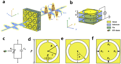
The micro-structure of the reconfigurable chiral metasurface and its operation principle of the electrically controlled broadband polarization conversion are schematically illustrated in Fig. 1. The chiral metasurface is composed of three-functional metallic layers, and the three layers with a thickness of t = 0.035 mm are separated by dielectric substrates with a relative dielectric constant of 2.65 and a thickness of h = 1.55 mm. The patterned metallic arrays can be seen from the perspective view of a unit cell of the metasurface (Fig. 1b) and detailed micro-structures on different layers (Fig. 1d–f). The functional layers are composed of complementary split/non-split ring resonator arrays with a period of p = 10 mm. The anisotropy split ring resonator array of the metasurface enables the polarization conversion and AT effect of electromagnetic waves. A complementary open splitting circle with 45°-rotated in the middle layer provides the opportunity to achieve chiral coupling in the metasurface which has been demonstrated to be of fundamental importance in realizing metasurfaces operating in a broadband manner.24 To achieve dynamic manipulation of the polarization, we need to change the bias voltage of the PIN diodes loaded on the CSRRs. In practice, we use an array of metal vias to connect the circular patches of the top CSRR layer and the bottom CSRR layer, so the resistances of the PIN diodes can be controlled by applying the bias voltage on the first and third layer of the metal mesh grid, while the polarization state of the transmitted wave can be precisely controlled.For realizing the active tunability of the broadband polarization control in the metasurface, we use an array of PIN diodes [MACOM MA4AGP907] loaded between the gap of CSRRs. The Aluminum Gallium Arsenide (AlGaAs) flip-chip PIN diodes (MA4AGP907) have a small junction capacitance of 0.025 pF, so the PIN diode can be simply modeled as a parallel RC circuit with a constant capacitance and a tunable resistance (Fig. 1c).80 The variable resistance of the diodes changes from infinite to 4.2 Ω, while the bias voltage increases positively from 0 to +1.25 V. The diodes are divided into two pairs with opposite electric biasing for controlling the electric connection between the inside and outside of the annulus (Fig. 1b and f). Then the orientation of the CSRRs on the top layer can be reconfigured by precisely and continuously tuning biasing voltage on the metasurface. When a maximum forward voltage is applied, the incident x-polarized wave remains as x-polarized wave after passing through the metasurface, with a polarization rotation angle of 0° compared to the incident wave. However, if we reduce the applied voltage from the maximum forward voltage to negative voltage, the transmitted wave will be a y-polarized wave, and the polarization is rotated by 90° compared to the incident wave. The structure of the meta-unit (Fig. 1b) as well as the chiral coupling in the three CSRRs can be simply applying electric voltages. Then the polarization of the incident linearly polarized electromagnetic wave or light wave can be dynamically rotated from 0° to 90° in a broad functional band of the metasurface device.
For the polarization conversion properties of the proposed metasurface, we employed a finite difference time domain (FDTD) method based electromagnetic full wave solver for the numerical simulations in which the metallic resonant structures are set as PEC, and the electric circuit model parameters of the PIN diode are RD = 4.2 Ω and CD = 0.025 pF. The inner and outer radii of the bottom layer, middle layer and top layer of the metal element structure are R = 4.8 mm and r = 4.2 mm. The rings in a unit are symmetrically segmented by two metallic strips with a width of g![[thin space (1/6-em)]](https://www.rsc.org/images/entities/char_2009.gif) = 0.2
= 0.2![[thin space (1/6-em)]](https://www.rsc.org/images/entities/char_2009.gif) mm and θ = 45°. Periodic boundary conditions are set along the x-axis and y-axis of the element structure, and the linearly polarized electromagnetic wave propagates along the z-axis positive direction. The geometrical shape of metal resonant elements in the metasurface lacks mirror symmetry, which results in strong electromagnetic wave cross coupling in the structure. The cross coupling and corresponding polarization transformation ensure the AT effect in the wide frequency band.
mm and θ = 45°. Periodic boundary conditions are set along the x-axis and y-axis of the element structure, and the linearly polarized electromagnetic wave propagates along the z-axis positive direction. The geometrical shape of metal resonant elements in the metasurface lacks mirror symmetry, which results in strong electromagnetic wave cross coupling in the structure. The cross coupling and corresponding polarization transformation ensure the AT effect in the wide frequency band.
The cross-coupling and cross-polarization of electromagnetic waves cause the asymmetric propagation of electromagnetic waves in the metasurface, which is asymmetric to the opposite direction of propagation. Considering the plane electromagnetic wave incident to the metasurface structure in the positive direction (+z), the following equation can be obtained:81
 | (1) |
 | (2) |
The Jones matrix T is used to describe the relationship between the incident wave and transmitted wave and can be expressed as:
 | (3) |
 | (4) |
| PCRx = |tyx|2/(|tyx|2 + |txx|2) | (5) |
| PCRy = |txy|2/(|txy|2 + |tyy|2) | (6) |
| Tij = |tij| | (7) |
For opposite propagation directions, the difference of off-diagonal elements in the T-matrix is the main reason for the phenomenon of asymmetric transmission in the metasurface structure. The asymmetric transmission of an incident electromagnetic wave propagating in the opposite direction can be expressed by the intensity difference:
| Δxlin = |tfxx|2 + |tfyx|2 − |tbyx|2 − |tbxx|2 = |tfyx|2 − |tfxy|2 | (8) |
| Δylin =−Δxlin | (9) |
For linearly polarized electromagnetic waves tf(b)xx = tf(b)yy and tf(b)yx ≠ tf(b)xy; this means that the intensity and phase of the polarization state are different in opposite propagation directions. The electromagnetic simulation of the proposed transmissive unit is carried out with help of the finite-difference time-domain (FDTD) software named Gallop by using periodic boundary conditions. Numerical calculations were carried out to study the polarization conversion and asymmetric transmission effect of the linearly polarized electromagnetic wave normal incident to the metasurface structure along the z-axis in two states of PIN diodes. Fig. 2a shows the transmission coefficient of the electromagnetic wave propagating forward along the z-axis when the diode is on in the x direction and disconnected in the y direction (state 1). At this point, the y-polarized wave can excite the resonant mode of the top structure and realize the transmission of the y-polarized electromagnetic wave. It can be clearly seen that in the broadband range of 8.3–11.2 GHz, the cross-polarization transmission coefficient Tyx of the x-polarized wave transformed into a y-polarized wave exceeds 0.8 and reaches the maximum of 0.96 at 9.8 GHz. However, the transmission coefficient Txy is very small in this frequency band range, and the difference between Tyx and Txy leads to high polarization conversion. The transmission coefficient Txx without polarization conversion in the whole frequency band is far less than the cross-polarization transmission coefficient Tyx, that is, there is almost no transmission of the same polarization electromagnetic wave in the whole frequency band range. Fig. 2b shows the results for the case the diode is disconnected in the x direction and turned on in the y direction (state 2); the transmission coefficient of the electromagnetic wave propagates forward along the z-axis. At the top of the structure in the x polarization mode, at the same time, due to the underlying structure being in the x polarization mode, bottom and top with the same polarization mode, linearly polarized electromagnetic wave incident to the metasurface structure, the x-polarized wave can excite the resonant mode at the bottom, and the outgoing wave is also an x-polarized wave through the near-field coupling of the local mode between layers. As can be seen from the figure, an x-polarized linearly wave is transmitted. The transmission coefficient Txx reaches the maximum of 0.96 at 10.3 GHz and exceeds 0.8 at 7.8–10.8 GHz. And the transmission coefficient Tyy is very small in this band range. It can also be clearly seen that the transmission coefficient Tyx is very small, so there is no polarization conversion of the incident electromagnetic wave. In addition, state 3: the diode is disconnected in both the x and y directions and is presented in order to demonstrate the function of the metasurface.
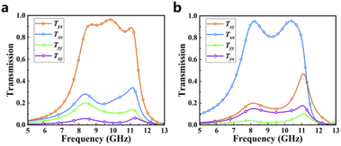 | ||
| Fig. 2 Transmission coefficient of the linearly polarized wave under normal incidence along the z-axis with different sets of the two paired PIN diode: state 1 (a) and state 2 (b). | ||
From the transmission spectra of the linearly polarized electromagnetic wave under different sets of biasing of the active diode, the highly efficient and broadband modulation on the polarization conversion of linearly polarized incidence can be realized by changing the setting of the resistance of the two paired diode. Intuitively, we expected to achieve continuously controlled polarization conversion in a broadband manner by precisely tuning the setup of resistance between state 1, state 3 and state 2. The continuous adjustment of the transmission coefficient and cross-polarization transmission coefficient by changing the resistance of the diodes in the two directions is confirmed through numerical simulations as shown in Fig. 3. When the resistance R1 = 4.2 Ω in the x direction and R2 = ∞ in the y direction, the cross-polarization transmission coefficient Tyx is about 0.96, and the transmission coefficient Txx is about 0.3, corresponding to state 1. Tyx decreases and Txx increases when R1 increases and R2 remains constant. Tyx = 0.58 and Txx = 0.8 when R1 and R2 are infinite, corresponding to state 3. Then, as R1 remains constant, Tyx continues to decrease, and Txx continues to increase as R2 increases until state 2 is reached when R1 = ∞ and R2 = 4.2 Ω and Tyx = 0.2 and Txx = 0.96. Therefore, the polarization state can be dynamically and continuously changed by adjusting the parameters of the diode, so as to realize the polarization conversion of the x-polarized wave to a y-polarized wave when the linearly polarized electromagnetic wave is incident on the metasurface or only the linearly polarized electromagnetic wave passes through the metasurface.
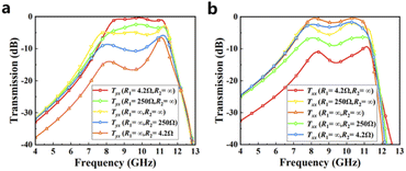 | ||
| Fig. 3 Calculated transmission spectra for cross-polarization (a) Tyx and co-polarization (b) Txx for the designed metasurface with different resistance parameters. | ||
To elucidate the physical mechanism of the broadband and tunable polarization transformation in the metasurface, we calculated the electric field distribution around the metasurface under different sets of resistances as shown in Fig. 4. It can be seen that the incident wave of x-polarization changes the degree of polarization rotation after passing through the super-surface with different voltages applied. We can conclude that the polarization control is achieved by adjusting the coupling effect between the local resonance modes of each layer through the 45° angular deflection of the intermediate layer. Therefore, the characteristics of the electromagnetic wave can be dynamically regulated by controlling the conduction direction of the top diode. The polarization conversion and asymmetric transmission effect of electromagnetic waves can be realized when the diode is in state 1: x direction, and the diode is disconnected in the y direction. When the diode is disconnected in the x direction and turned on in the y direction in state 2, the electromagnetic wave does not have these characteristics.
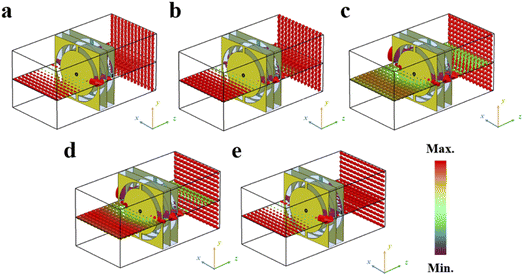 | ||
| Fig. 4 Investigation on the electric field incident on and passing through the metasurface with different sets of resistance parameters corresponding to Fig. 3: (a) R1 = 4.2 Ω; R2 = ∞. (b) R1 = 250 Ω; R2 = ∞. (c) R1 = ∞; R2 = ∞. (d) R1 = ∞; R2 = 250 Ω. (e) R1 = ∞; R2 = 4.2 Ω. | ||
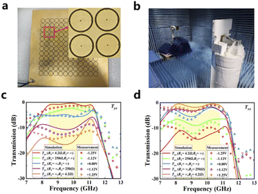
In this work, to verify the metasurface performance experimentally, we used the printed circuit board (PCB) technique to fabricate a metasurface sample containing 144 (12 × 12) unit cells as shown in Fig. 5a. We measured the cross-polarization transfer coefficient and co-polarization transfer coefficient at −1.25 V to 0 V to +1.25 V bias; the variable resistance R1 of the diode changes from R1 = 4.2 Ω to infinite, while the bias voltage decreases in reverse from −1.25 V to 0, and the variable resistance R2 of the diode changes from infinite to R2 = 4.2 Ω, while the bias voltage increases positively from 0 to +1.25 V (Fig. 5b is the metasurface under testing). The transmission spectra at five sets of bias voltages are experimentally studied, and the simulation results are given for the corresponding circuit model equivalent parameters. We compared the experimental and simulation results in Fig. 5c and d. It is clearly shown: (i) the incident x-polarized wave at state 1: −1.25 V bias voltage (R1 = 4.2 Ω; R2 = ∞) and state 2: +1.25 V bias voltage (R1 = ∞; R2 = 4.2 Ω) has a high cross-polarization transfer coefficient and co-polarization transfer coefficient over a wide frequency range; (ii) the ratio of the converted y-polarization wave can be dramatically and continuously modulated by tuning the biasing voltage on the metasurface sample.
We further studied the asymmetric transmission feature of the metasurface. The measured and simulated results of the asymmetric transmission spectra and polarization conversion efficiency of the diode in different states are presented in Fig. 6. The maximum value of Δx in simulation is 0.92 at 9.8 GHz (Fig. 6a), and the asymmetric transmission characteristic is displayed in the 8.4–11.2 GHz band in state 1. For state 2, the maximum value of Δx is 0.19 at 11.0 GHz, and no asymmetric transmission characteristic is displayed. Fig. 6b shows that the measured results for Δx(y) in states 1 and 2 agreed well with the theoretical calculations. The polarization conversion rate (PCR) represents the conversion amount of one linearly polarized wave to another. According to formula (5) and (6), the PCR of the linearly polarized electromagnetic wave can be calculated. Fig. 6c shows the comparison of polarization conversion rates between the simulation and experiment. As for the simulated results, it can be seen that the PCR value of x-polarized wave exceeds 93% in the broadband 8.1 GHz to 11.6 GHz, and the PCR value of the y-polarized wave is less than 10% at the same operating frequency. Therefore, in this case, the electromagnetic wave realizes the polarization conversion of the x-polarized wave incident to the y-polarized wave. The experimentally measured results are consistent with the simulated results. The active metasurface with three specifically designed complementary structures is proved to be a good platform for achieving broadband tunable polarization conversion and asymmetric transmission.
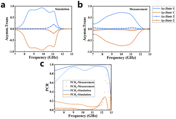 | ||
| Fig. 6 Simulated (a) and measured (b) asymmetric transmission spectra and the (c) polarization conversion ratio for the chiral metasurface operating in different states. | ||
Conclusions
In summary, we demonstrate a reconfigurable chiral metasurface with stacked CSRR arrays. The orientation of the CSRRs in different layers is properly designed and actively reconfigured considering the electric connection with PIN diodes. The chiroptical response or chiral coupling in the stacked CSRRs can be actively reconfigured by changing the biased voltage on the metasurface, and the cross-polarization transmission coefficient and transmission coefficient are continuously adjusted to realize the continuous polarization manipulation. The structures designed in this paper are practical in the microwave section and can be used as a frequency selector and converter among others to achieve multi-functional manipulation of electromagnetic waves through the reconfigurable metasurface structure in the broadband range. The proposed strategy for achieving multi-functional polarization control with a reconfigurable chiral metasurface can be extended to the optical regime considering the active research studies on actively modulated optical metasurfaces.Author contributions
All authors commented on the manuscript.Conflicts of interest
There are no conflicts to declare.Acknowledgements
We are grateful for financial support from the National Natural Science Foundation of China (Grants No. 11874285, 12074314, 61621001, 61925504, 6201101335, 62020106009, 62061136008, and 62111530053).Notes and references
- H.-T. Chen, A. J. Taylor and N. Yu, Rep. Prog. Phys., 2016, 79, 076401 CrossRef PubMed.
- A. Arbabi, Y. Horie, M. Bagheri and A. Faraon, Nat. Nanotechnol., 2015, 10, 937–943 CrossRef CAS PubMed.
- I. Yamada, K. Takano, M. Hangyo, M. Saito and W. Watanabe, Opt. Lett., 2009, 34, 274–276 CrossRef PubMed.
- C.-Y. Chen, T.-R. Tsai, C.-L. Pan and R.-P. Pan, Appl. Phys. Lett., 2003, 83, 4497–4499 CrossRef CAS.
- M. Mutlu, A. E. Akosman and E. Ozbay, Opt. Lett., 2012, 37, 2094–2096 CrossRef.
- K. Wiesauer and C. Jördens, J. Infrared, Millimeter, Terahertz Waves, 2013, 34, 663–681 CrossRef.
- N. Yu and F. Capasso, Nat. Mater., 2014, 13, 139–150 CrossRef CAS PubMed.
- A. V. Kildishev, A. Boltasseva and V. M. Shalaev, Science, 2013, 339, 1232009 CrossRef PubMed.
- N. Shitrit, I. Yulevich, E. Maguid, D. Ozeri, D. Veksler, V. Kleiner and E. Hasman, Science, 2013, 340, 724–726 CrossRef CAS.
- B. Groever, W. T. Chen and F. Capasso, Nano Lett., 2017, 17, 4902–4907 CrossRef CAS PubMed.
- S. Sun, Q. He, S. Xiao, Q. Xu, X. Li and L. Zhou, Nat. Mater., 2012, 11, 426–431 CrossRef CAS PubMed.
- X. Chen, L. Huang, H. Mühlenbernd, G. Li, B. Bai, Q. Tan, G. Jin, C.-W. Qiu, S. Zhang and T. Zentgraf, Nat. Commun., 2012, 3, 1198 CrossRef PubMed.
- S. Chen, W. Liu, Z. Li, H. Cheng and J. Tian, Adv. Mater., 2020, 32, 1805912 CrossRef CAS PubMed.
- W. Zhu, Y. Fan, R. Yang, G. Geng, Q. Fu, C. Gu, J. Li and F. Zhang, Adv. Funct. Mater., 2022, 32, 2200013 CrossRef CAS.
- Y. Zhang, H. Liu, H. Cheng, J. Tian and S. Chen, Opto-Electron. Adv., 2020, 3, 200002 CAS.
- Y. Guo, X. Ma, M. Pu, X. Li, Z. Zhao and X. Luo, Adv. Opt. Mater., 2018, 6, 1800592 CrossRef.
- S. Zhang, Y.-S. Park, J. Li, X. Lu, W. Zhang and X. Zhang, Phys. Rev. Lett., 2009, 102, 023901 CrossRef PubMed.
- E. Plum, J. Zhou, J. Dong, V. A. Fedotov, T. Koschny, C. M. Soukoulis and N. I. Zheludev, Phys. Rev. B: Condens. Matter Mater. Phys., 2009, 79, 035407 CrossRef.
- J. Hao, Y. Yuan, L. Ran, T. Jiang, J. A. Kong, C. T. Chan and L. Zhou, Phys. Rev. Lett., 2007, 99, 063908 CrossRef PubMed.
- S. Zhang, J. Zhou, Y.-S. Park, J. Rho, R. Singh, S. Nam, A. K. Azad, H.-T. Chen, X. Yin, A. J. Taylor and X. Zhang, Nat. Commun., 2012, 3, 942 CrossRef PubMed.
- J. Zhou, D. R. Chowdhury, R. Zhao, A. K. Azad, H.-T. Chen, C. M. Soukoulis, A. J. Taylor and J. F. O'Hara, Phys. Rev. B: Condens. Matter Mater. Phys., 2012, 86, 035448 CrossRef.
- Y. Ye and S. He, Appl. Phys. Lett., 2010, 96, 203501 CrossRef.
- Y. Zhao and A. Alù, Phys. Rev. B: Condens. Matter Mater. Phys., 2011, 84, 205428 CrossRef.
- Z. Wei, Y. Cao, Y. Fan, X. Yu and H. Li, Appl. Phys. Lett., 2011, 99, 221907 CrossRef.
- F. Neubrech, M. Hentschel and N. Liu, Adv. Mater., 2020, 32, 1905640 CrossRef CAS PubMed.
- B. Wang, W. Liu, M. Zhao, J. Wang, Y. Zhang, A. Chen, F. Guan, X. Liu, L. Shi and J. Zi, Nat. Photonics, 2020, 14, 623–628 CrossRef CAS.
- Y. Chen, W. Du, Q. Zhang, O. Ávalos-Ovando, J. Wu, Q.-H. Xu, N. Liu, H. Okamoto, A. O. Govorov, Q. Xiong and C.-W. Qiu, Nat. Rev. Phys., 2022, 4, 113–124 CrossRef.
- H. X. Xu, G. Hu, Y. Wang, C. Wang, M. Wang, S. Wang, Y. Huang, P. Genevet, W. Huang and C. W. Qiu, Light: Sci. Appl., 2021, 10, 75 CrossRef CAS PubMed.
- S. Liu, T. Jun Cui, A. Noor, Z. Tao, H. Chi Zhang, G. Dong Bai, Y. Yang and X. Yang Zhou, Light: Sci. Appl., 2018, 7, 18008 CrossRef CAS PubMed.
- M. Jia, Z. Wang, H. Li, X. Wang, W. Luo, S. Sun, Y. Zhang, Q. He and L. Zhou, Light: Sci. Appl., 2019, 8, 16 CrossRef PubMed.
- V. A. Fedotov, P. L. Mladyonov, S. L. Prosvirnin, A. V. Rogacheva, Y. Chen and N. I. Zheludev, Phys. Rev. Lett., 2006, 97, 167401 CrossRef CAS PubMed.
- R. Singh, E. Plum, C. Menzel, C. Rockstuhl, A. K. Azad, R. A. Cheville, F. Lederer, W. Zhang and N. I. Zheludev, Phys. Rev. B: Condens. Matter Mater. Phys., 2009, 80, 153104 CrossRef.
- C. Menzel, C. Helgert, C. Rockstuhl, E. B. Kley, A. Tünnermann, T. Pertsch and F. Lederer, Phys. Rev. Lett., 2010, 104, 253902 CrossRef CAS PubMed.
- C. Huang, Y. Feng, J. Zhao, Z. Wang and T. Jiang, Phys. Rev. B: Condens. Matter Mater. Phys., 2012, 85, 195131 CrossRef.
- M. Kang, J. Chen, H.-X. Cui, Y. Li and H.-T. Wang, Opt. Express, 2011, 19, 8347–8356 CrossRef.
- Y. Cheng, Y. Nie, X. Wang and R. Gong, Appl. Phys. A, 2013, 111, 209–215 CrossRef CAS.
- J. Shi, X. Liu, S. Yu, T. Lv, Z. Zhu, H. Feng Ma and T. Jun Cui, Appl. Phys. Lett., 2013, 102, 191905 CrossRef.
- F. Zhang, M. Pu, X. Li, P. Gao, X. Ma, J. Luo, H. Yu and X. Luo, Adv. Funct. Mater., 2017, 27, 1704295 CrossRef.
- Y. Huang, L. Yang, J. Li, Y. Wang and G. Wen, Appl. Phys. Lett., 2016, 109, 054101 CrossRef.
- S. Chen, Y. Zhang, Z. Li, H. Cheng and J. Tian, Adv. Opt. Mater., 2019, 7, 1801477 CrossRef.
- K. Y. Cheng, Z. Y. Wei, Y. C. Fan, X. M. Zhang, C. Wu and H. Q. Li, Adv. Opt. Mater., 2019, 7, 1900016 CrossRef.
- S. H. A. Bokhari and H. M. Cheema, J. Appl. Phys., 2020, 128, 063102 CrossRef CAS.
- C. X. Huang, J. J. Zhang, L. Wu, C. Zhang, J. Yang, L. X. Yang, J. C. Ke, L. Bai, Q. Cheng and T. J. Cui, Adv. Theory Simul., 2020, 3, 2000109 CrossRef.
- M. I. Khan, B. Hu, A. Amanat, N. Ullah, M. J. I. Khan and A. R. Khalid, J. Phys. D: Appl. Phys., 2020, 53, 305004 CrossRef CAS.
- F. Long, S. Yu, N. Kou, C. Zhang, Z. Ding and Z. Zhang, J. Appl. Phys., 2020, 127, 023104 CrossRef.
- T. Ullah and A. Rashid, Microw. Opt. Technol. Lett., 2020, 63, 226–234 CrossRef.
- L. Zhang, P. Zhou, H. Chen, H. Lu, H. Xie, L. Zhang, E. Li, J. Xie and L. Deng, Sci. Rep., 2016, 6, 33826 CrossRef CAS PubMed.
- J.-S. Li and F.-Q. Bai, Opt. Mater. Express, 2020, 10, 1853–1861 CrossRef CAS.
- T. Lv, X. Chen, G. Dong, M. Liu, D. Liu, C. Ouyang, Z. Zhu, Y. Li, C. Guan, J. Han, W. Zhang, S. Zhang and J. Shi, Nanophotonics, 2020, 9, 3235–3242 CrossRef.
- W. Pan, Q. Chen, Y. Ma, X. Wang and X. Ren, Opt. Commun., 2020, 459, 124901 CrossRef CAS.
- Y. Rao, L. Pan, C. Ouyang, Q. Xu, L. Liu, Y. Li, J. Gu, Z. Tian, J. Han and W. Zhang, Opt. Express, 2020, 28, 29855–29864 CrossRef CAS PubMed.
- Y. Ren, C. Jiang and B. Tang, J. Opt. Soc. Am. B, 2020, 37, 3379–3385 CrossRef CAS.
- L. Zhou, Y. Wang, J. Zhou, J. Ding, M. Lu and T. Sang, Appl. Opt., 2020, 59, 6868–6872 CrossRef PubMed.
- Y. Tian, Z. Chen, F.-F. Ren, Q. Du and Z. Li, Front. Phys., 2021, 9, 676840 CrossRef.
- W. Xiong, C. W. Hsu, Y. Bromberg, J. E. Antonio-Lopez, R. Amezcua Correa and H. Cao, Light: Sci. Appl., 2018, 7, 54 CrossRef PubMed.
- M. X. Ren, W. Wu, W. Cai, B. Pi, X. Z. Zhang and J. J. Xu, Light: Sci. Appl., 2017, 6, e16254 CrossRef CAS PubMed.
- S. Huang, C. Song, G. Zhang and H. Yan, Nanophotonics, 2017, 6, 1191–1204 CAS.
- Y. Y. Ji, F. Fan, X. H. Wang and S. J. Chang, Opt. Express, 2018, 26, 12852–12862 CrossRef CAS PubMed.
- Y. Li, J. Lin, H. Guo, W. Sun, S. Xiao and L. Zhou, Adv. Opt. Mater., 2020, 8, 1901548 CrossRef CAS.
- J. Zhang, X. Wei, I. D. Rukhlenko, H.-T. Chen and W. Zhu, ACS Photonics, 2020, 7, 265–271 CrossRef CAS.
- Y. Zhang, Y. Feng, B. Zhu, J. Zhao and T. Jiang, Opt. Express, 2015, 23, 27230–27239 CrossRef CAS PubMed.
- A. V. Pogrebnyakov, J. A. Bossard, J. P. Turpin, J. D. Musgraves, H. J. Shin, C. Rivero-Baleine, N. Podraza, K. A. Richardson, D. H. Werner and T. S. Mayer, Opt. Mater. Express, 2018, 8, 2264–2275 CrossRef CAS.
- Y. Qu, Q. Li, L. Cai, M. Pan, P. Ghosh, K. Du and M. Qiu, Light: Sci. Appl., 2018, 7, 26 CrossRef.
- J. Tian, H. Luo, Y. Yang, F. Ding, Y. Qu, D. Zhao, M. Qiu and S. I. Bozhevolnyi, Nat. Commun., 2019, 10, 396 CrossRef.
- J. Tian, H. Luo, Y. Yang, F. Ding, Y. Qu, D. Zhao, M. Qiu and S. I. Bozhevolnyi, Nat. Commun., 2019, 10, 396 CrossRef.
- P. Pitchappa, A. Kumar, S. Prakash, H. Jani, R. Medwal, M. Mishra, R. S. Rawat, T. Venkatesan, N. Wang and R. Singh, Adv. Funct. Mater., 2021, 31, 2100200 CrossRef CAS.
- W. Zhu, Y. Fan, C. Li, R. Yang, S. Yan, Q. Fu, F. Zhang, C. Gu and J. Li, Nanoscale, 2020, 12, 8758–8767 RSC.
- Y. Fan, N.-H. Shen, F. Zhang, Q. Zhao, H. Wu, Q. Fu, Z. Wei, H. Li and C. M. Soukoulis, Adv. Opt. Mater., 2019, 7, 1800537 CrossRef.
- Z. Wei, X. Liu and Y. Cao, Front. Phys., 2020, 8, 90 CrossRef.
- Y. Fan, X. He, F. Zhang, W. Cai, C. Li, Q. Fu, N. V. Sydorchuk and S. L. Prosvirnin, Research, 2021, 2021, 9754083 Search PubMed.
- R. Yang, J. Lou, F. Zhang, W. Zhu, J. Xu, T. Cai, Q. Fu, H. Li and Y. Fan, Adv. Photonics Res., 2021, 2, 2100103 CrossRef.
- C. Huang, J. Liao, C. Ji, J. Peng, L. Yuan and X. Luo, Adv. Opt. Mater., 2021, 9, 2001950 CrossRef CAS.
- C. Huang, C. Zhang, J. Yang, B. Sun, B. Zhao and X. Luo, Adv. Opt. Mater., 2017, 5, 1700485 CrossRef.
- H. Kwon and A. Faraon, ACS Photonics, 2021, 8, 2980 CrossRef CAS PubMed.
- Y. Yang, H. Kim, T. Badloe and J. Rho, Nanophotonics, 2022, 11, 4123–4133 CrossRef.
- K. Tanaka, D. Arslan, S. Fasold, M. Steinert, J. Sautter, M. Falkner, T. Pertsch, M. Decker and I. Staude, ACS Nano, 2020, 14, 15926 CrossRef PubMed.
- D. Wang, Y. Hwang, Y. Dai, G. Si, S. Wei, D. Y. Choi, D. E. Gomez, A. Mitchell, J. Lin and X. Yuan, Small, 2019, 15, e1900483 CrossRef PubMed.
- R. Zhang, Q. Zhao, X. Wang, K. M. Lau, T. K. Yung, J. Li and W. Y. Tam, Nanophotonics, 2022, 11, 495 CrossRef.
- H. Cheng, Z. Liu, S. Chen and J. Tian, Adv. Mater., 2015, 27, 5410–5421 CrossRef CAS PubMed.
- Z. Wei, H. Li, W. Xu and Y. Cao, Front. Phys., 2021, 8, 632902 CrossRef.
- C. Menzel, C. Rockstuhl and F. Lederer, Phys. Rev. A: At., Mol., Opt. Phys., 2010, 82, 053811 CrossRef.
- C. Menzel, C. Helgert, C. Rockstuhl, E. B. Kley, A. Tunnermann, T. Pertsch and F. Lederer, Phys. Rev. Lett., 2010, 104, 253902 CrossRef CAS PubMed.
| This journal is © The Royal Society of Chemistry 2022 |

