
 Open Access Article
 This Open Access Article is licensed under a Creative Commons Attribution-Non Commercial 3.0 Unported Licence
N-doped graphene for electrocatalytic O2 and CO2 reduction
Ruguang
Ma
 a,
Kuikui
Wang
b,
Chunjie
Li
a,
Chundong
Wang
c,
Aziz
Habibi-Yangjeh
*d and
Guangcun
Shan
*e
a,
Kuikui
Wang
b,
Chunjie
Li
a,
Chundong
Wang
c,
Aziz
Habibi-Yangjeh
*d and
Guangcun
Shan
*e
aSchool of Materials Science and Engineering, Suzhou University of Science and Technology, 99 Xuefu Road, Suzhou, 215011, China
bInstitute of Materials for Energy and Environment, Laboratory of New Fiber Materials and Modern Textile, Growing Basis for State Key Laboratory, College of Materials Science and Engineering, Qingdao University, Qingdao 266071, China
cSchool of Optical and Electronic Information, Wuhan National Laboratory for Optoelectronics, Optics Valley Laboratory, Huazhong University of Science and Technology, Wuhan 430074, PR China
dDepartment of Chemistry, Faculty of Science, University of Mohaghegh Ardabili, Ardabil, Iran. E-mail: ahabibi@uma.ac.ir
eSchool of Instrumentation Science and Opto-electronics Engineering, Beihang University, No. 37 XueYuan Road, Beijing 100083, China. E-mail: gcshan@buaa.edu.cn
First published on 6th September 2022
Abstract
The electrocatalytic CO2 reduction reaction (CO2RR) and oxygen reduction reaction (ORR) are important approaches to realize energy conversion and sustainable development. However, sluggish reaction kinetics severely hinders the practical application of devices related to these reactions. N-doped graphene (NG) with unique properties exhibits great potential in catalyzing the CO2RR and ORR, which is attributed to the electron redistribution. In this review, we start from the fundamental properties of NG, especially emphasizing the changes caused by N doping. Then the synthetic methods are summarized by classifying them into top-down strategies and bottom-up strategies. Subsequently, the applications of NG in the ORR and CO2RR are discussed and the effects of electronic structure on the electrocatalytic activity are highlighted. Finally, we give our own perspective on the future research direction of NG in the applications of the ORR and CO2RR.
1. Introduction
To mitigate the global climate problem and achieve carbon neutrality, the conversion and storage of renewable energy highly demand advanced electrochemical technologies, most of which involve various electrocatalytic reactions. For instance, the oxygen reduction reaction (ORR) is a critical electrochemical process in metal-air batteries and fuel cells.1–4 The electrocatalytic CO2 reduction reaction (CO2RR) is especially an effective strategy to re-balance the carbon cycle and to harvest value-added chemical products.5–7 However, these electrocatalytic processes have been severely limited by the sluggish reaction kinetics, which necessitate efficient electrocatalysts with good selectivity and durability. Although the state-of-art noble metal-based electrocatalysts have been used in these reactions,8,9 the scarcity accompanied by high cost hampers the large-scale applications of these sustainable energy technologies. It is highly desirable to discover and design cost-effective electrocatalysts.Among many non-precious-metal materials, graphene consisting of sp2-hybridized carbon atoms arranged in a honeycomb lattice has been intensively studied as a potential candidate,10 due to the outstanding electronic conductivity, large specific surface area, and good mechanical properties arising from the unique two-dimensional (2D) structure.11,12 As a spark, it also inspires the exploration of other 2D materials and broadens the 2D material family, including transition dichalcogenides (TMDs), MXenes, hexagonal boron nitride (h-BN), etc.13–16 Graphene can be built into different nanostructures, such as graphene quantum dots,17 graphene nanoribbons,18 and graphene nanomeshes19 as well as recently emerged “magic-angle graphene”,20 demonstrating various novel properties,21 which attract the intensive interest of researchers around the world. Moreover, heteroatom doping into graphene also plays an important role in the modulation of fundamental properties.22 Among various heteroatoms, the doping of nitrogen (N) atoms usually leads to strong charge polarization in the carbon plane due to the remarkable difference of electronegativity between nitrogen (χ = 3.04 on the Pauling scale) and carbon (χ = 2.55).23
Since the pioneering work of N-doped carbon nanotubes used for the electrocatalytic ORR,24 N-doped carbon materials gained special attention for electrocatalysis applications.25 In particular, N-doped graphene (NG) has been placed at the center of the spotlight, due to the unique characteristics and advantages of the structure and properties, including the induced charge redistribution and defects by N doping.26 Moreover, NG has been extensively explored as an electrocatalyst for the CO2RR to play an ever-increasingly important role in realizing carbon neutrality and ecosystem protection.27–29 Therefore, it is of significance to review the recent advances of NG applications in these reactions and to figure out the opportunities and challenges in the future.
In this review, we primarily start from the fundamental properties of NG followed by the synthesis methods. Then, we summarize the applications of NG in the ORR and CO2RR and emphasize the effects of the electronic structure on the electrocatalytic activity. Based on the specific reaction pathway, we try to construct the correlation between the physicochemical properties and electrocatalytic activity and to elucidate the electrocatalytic reaction mechanism. Finally, we will provide an outlook on the future research direction and give our own perspective on NG in the applications of the ORR and CO2RR.
2. Fundamental properties
Graphene is an sp2-hybridized carbon layer with zero bandgap. Heteroatom doping into graphene, especially N doping, can effectively tailor its electronic structure and other intrinsic properties, broadening the application fields.30 There are usually several N species in N-doped graphene (NG), including graphitic N, pyridinic N, pyrrolic N, amide N and N oxides as shown in Fig. 1a. The successful doping of N atoms into the graphene lattice can be revealed by the scanning tunneling microscopy (STM) image (Fig. 1b) and simulated STM image computed from the local density of states for graphitic doping (Fig. 1c).31 The introduction of an N dopant at different locations leads to different electronic states. For example, the formation of the lone pair at pyridinic N makes the N atom negatively charged (Fig. 1d).32 And the spatial propagation of the localized π states can be seen in the STM simulations at a negative bias of −1.0 V, as shown in Fig. 1e and f.32 The charge transfer caused by N doping induces net positive charge at adjacent C atoms, which facilitates the attraction of electrons from the anode and the ORR.33 The charge redistribution also changes the chemisorption mode of the O2 molecule from the usual end-on adsorption (Pauling model) to side-on adsorption (Yeager model),24 which could effectively weaken the O–O bonding in parallel diatomic adsorption. With the development of synthetic methods and advanced characterization techniques, the understanding on the fundamental properties of NG has been deepened gradually.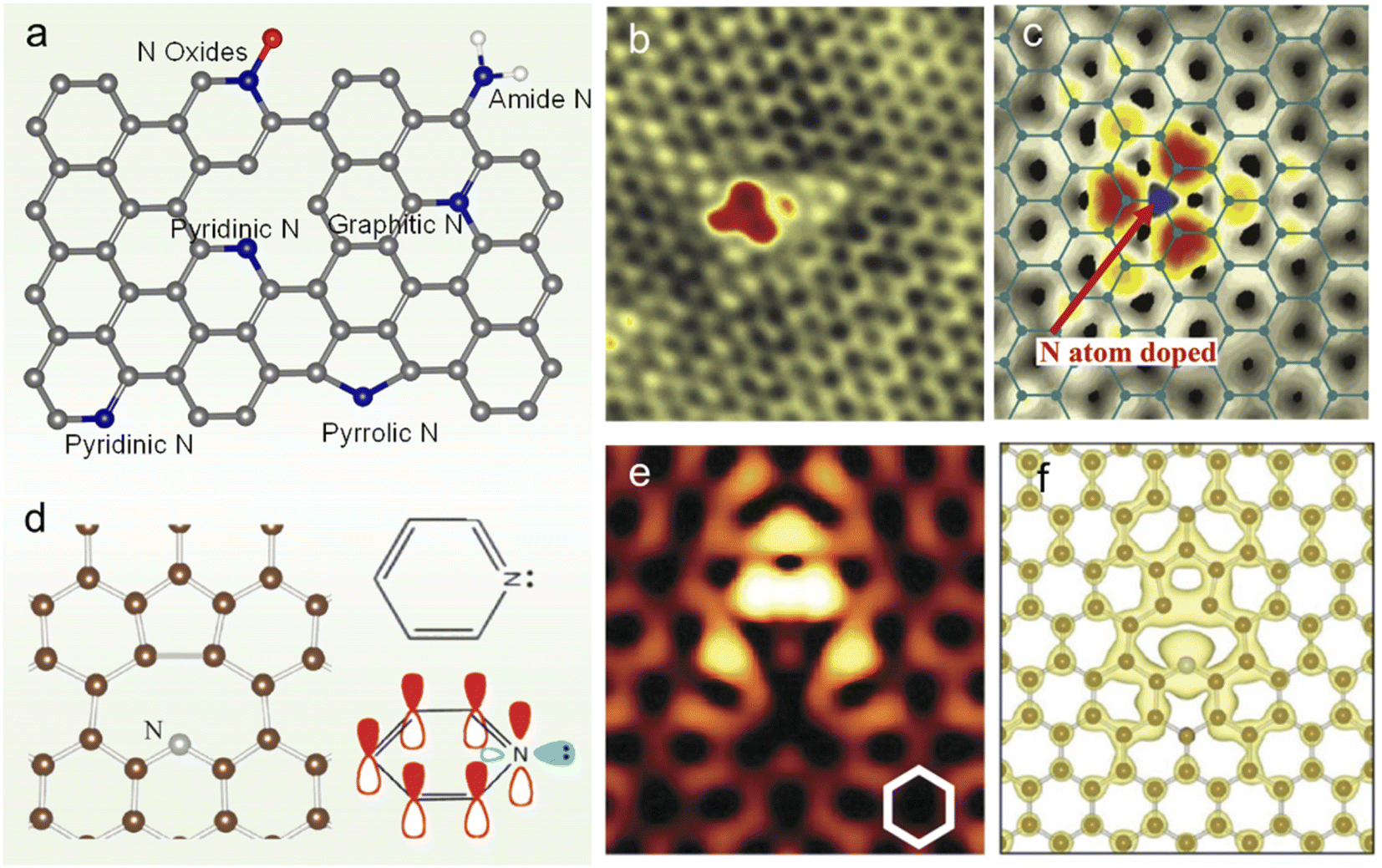 | ||
| Fig. 1 (a) Scheme of NG with different N species, (b) STM image of monolayer NG and (c) its simulation by DFT calculations. (d) Equilibrium geometry of pyridinic N calculated by DFT (left panel) and schematic representation of pz orbitals in pyridinic N (right panel). (e) Simulated STM images (constant-current mode) for pyridinic N graphene at a bias voltage of −1.0 V. The N atom is placed at the center of the image. (f) DFT equilibrium geometry and isosurface plot of electron density at 1.5 × 10⁻³ electrons/Å3 integrated from the Fermi level to −0.7 eV. (b and c) Reprinted with permission from ref. 31, copyright © 2011 AAAS. (d–f) Reprinted from ref. 29 with permission from ref. 32, copyright © American Physical Society 2012. | ||
The band structure and density of states (DOS) calculated by the ab initio method and tight-binding (TB) model indicate an obvious bandgap opening, as shown in Fig. 2a & b.34 When different concentrations of N dopants are randomly distributed in one sublattice, the bandgap (Eg) ranges from 45, 110, 340 to 550 meV for various N concentrations corresponding to 0.5, 1, 4, and 8 at% (Fig. 2b).34 Experimentally, compared to that of pristine graphene, the Raman spectrum of NG shows an obvious D′-band, which is attributed to the intravalley double resonance scattering processes (Fig. 2c).35 And a more intense D-band is also shown, which probably originates from the elastically scattered photo-excited electron created by the large number of N atoms embedded in the graphene lattice before emitting a phonon. There is also an obvious downshift of the G-band and 2D band caused by the movement of the Fermi level.
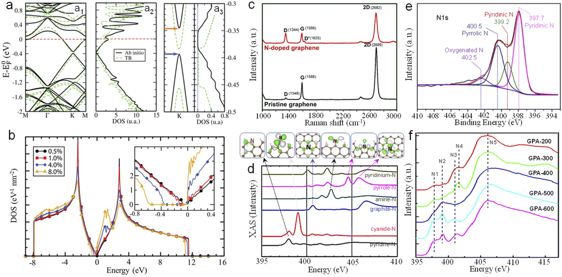 | ||
| Fig. 2 (a) Ab initio and tight-binding (a1) band structures and (a2) density of states (DOS) of a 10 × 10 graphene supercell containing one substitutional N dopant. (a3) Zoomed view of the band structure (left panel) and DOS (right panel) close to the band gap. (b) DOS of graphene containing various concentrations of N dopants randomly distributed in one sublattice; inset: zoomed view of the DOS in the band gap region. (c) Raman spectrum of NG and pristine graphene. (d) Theoretically calculated XAS of NG. (e) High resolution N1s XPS spectra of NG obtained by annealing glucose and melamine at 550 °C firstly and then at 800 °C. (f) N K-edge XANES spectra of NG prepared by annealing a GO/urea mixture at different temperatures (200, 300, 400, 500 and 600 °C). (a and b) Reprinted with permission from ref. 34, copyright © American Chemical Society 2013. (d) Reprinted with permission from ref. 38, copyright © American Chemical Society American Physical Society 2011. (f) Reprinted with permission from ref. 40, copyright© Elsevier Ltd 2011. | ||
Different N configurations in NG have different influences on the electrocatalytic performance. Theoretical studies reveal that the doped N located at the zigzag edge of graphene can activate the neighboring edge carbons toward the ORR, while for a given zigzag edge, the presence of pyridinic N significantly reduces the inherent ORR activity of graphene.36,37 Moreover, Wang et al. studied the nitrogen configuration and its location (armchair or zigzag edge) in NG by using theoretical calculations and presented the K-edge X-ray absorption spectra (XAS) and emission spectra (XES) as well as the final (initial)-state wave functions (Fig. 2d).38 Experimentally, the characteristic peaks can be measured and deconvoluted by X-ray photoelectron spectroscopy (XPS) and X-ray absorption near-edge structure spectroscopy (XANES) as shown in Fig. 2e and f. The high-resolution XPS spectrum of N1s can be fitted into four peaks at around 397.7, 399.2, 400.5 and 402.5 eV, which are assigned to pyridinic N, pyrrolic N, graphitic N and oxygenated N, respectively (Fig. 2e).39 As shown in Fig. 2f, the N K-edge XANES spectrum of NG changes with the annealing temperature from 200 to 600 °C, indicating the corresponding variation of N species.40 Especially, the N5 peak at ∼406 eV in GPA-200 is ascribed to the σ* excitation of C–N bonds, while N4 at ∼402 eV can be attributed to the attachment of urea species. Moreover, amino induced small features at about 399 eV (N1 and N2) can also be observed. With the increase of temperature, the N4 peak gradually decreases and a strong N2 peak emerges. When the temperature reaches 500 °C, the N1 peak and N3 peak ascribed to the pyridinic type and graphitic type, respectively, are observed. And the graphitic N species become dominant with the N3 peak increasing greatly at 600 °C. These results provide significant guidance for the identification of N species in NG experimentally synthesized by different methods.
3. Synthetic methods
Generally, the synthesis of graphene can be classified into two main strategies: top-down and bottom-up methods.41,42 Top-down strategies refer to cutting or tearing graphite into graphene, including mechanical exfoliation, chemical ablation, electrochemical oxidation, plasma treatment, etc. Bottom-up methods realize the synthesis of graphene from molecular precursors containing a certain number of conjugated carbon atoms or from the gas-phase vapor growth. To realize the substitution or doping of N atoms into the graphene lattice, several treatment methods are usually employed.3.1 Top-down strategies
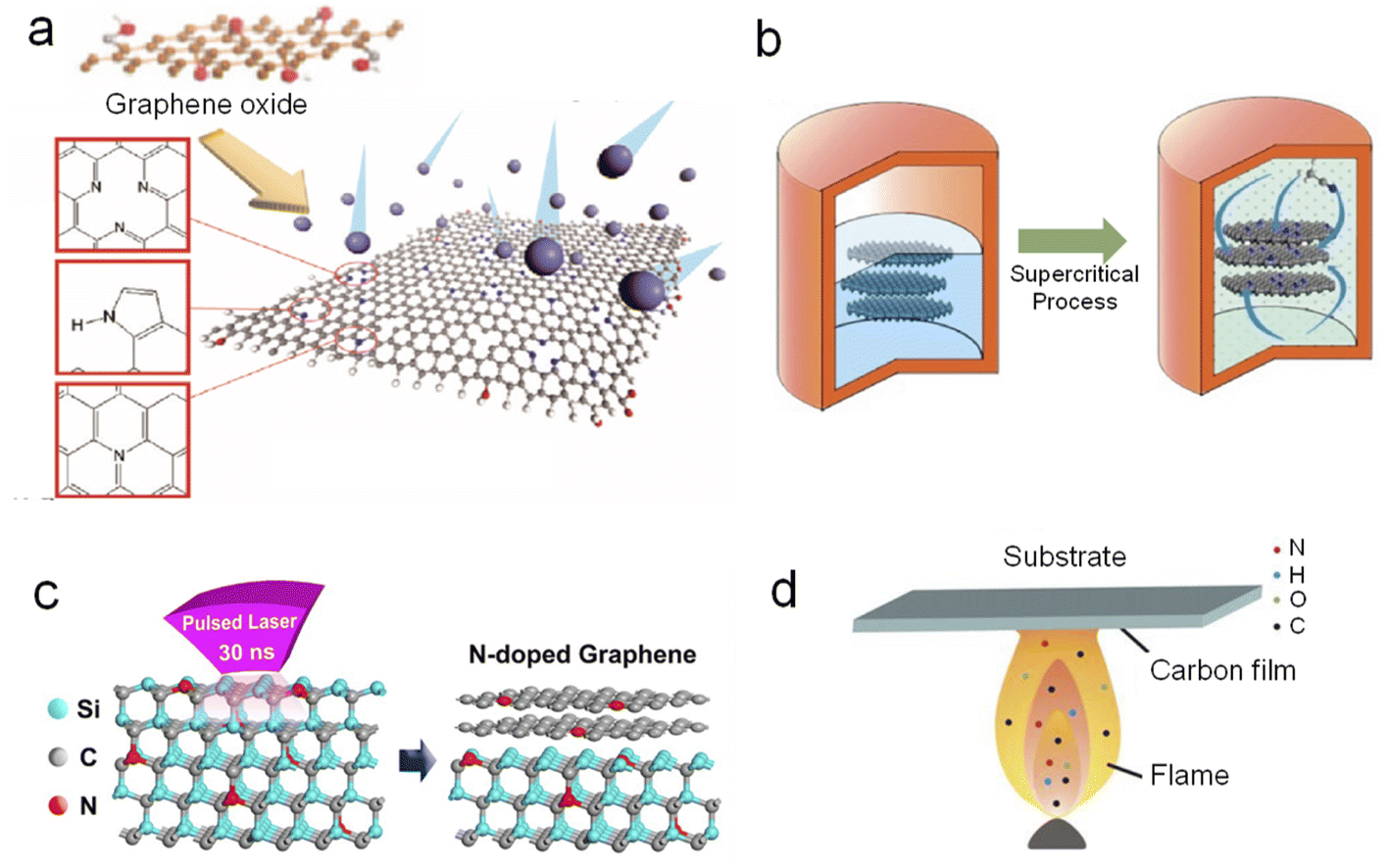 | ||
| Fig. 3 Synthetic methods of NG: (a) plasma treatment, (b) supercritical reaction, (c) pulsed laser irradiation, and (d) flame treatment. (a), (b) and (c) Reprinted with permission from ref. 56, 60, and 61, copyright© 2011 and 2014 American Chemical Society. (d) Reprinted from ref. 62, copyright© 2012 Elsevier B.V. | ||
There are also other methods used for synthesizing NG, which are not so popular as the abovementioned methods, for example, supercritical reaction (Figure 3b),60 pulsed laser irradiation (Fig. 3c),61 and flame treatment (Fig. 3d).62 The supercritical reaction is readily employed to prepare NG at a relatively low temperature of about 310 °C. In a typical procedure, few-layer graphene sheets (2 mg) were dispersed in acetonitrile (25 mL), and the mixture was transferred to a corundum-lined autoclave (50 mL).60 The autoclave was heated to 310 °C and an environment of supercritical reaction fluid was maintained within the autoclave. After a certain reaction time, N-doped graphene sheets can be harvested after centrifugation and rinsing. Laser irradiation can also provide enough heat for direct in situ growth of NG on an insulating substrate and does not need a complicated transfer process. By virtue of flame treatment, Pan's group prepared NG with dominant pyridine-N from amine plus ethanol flames.62 During the process, a Si substrate with a Ni film was inserted into the flame at 5.5 cm above a lamp for 1 min. A brown combustion product, i.e., NG, was observed on the substrate when it was withdrawn from the flame.
3.2 Bottom-up strategies
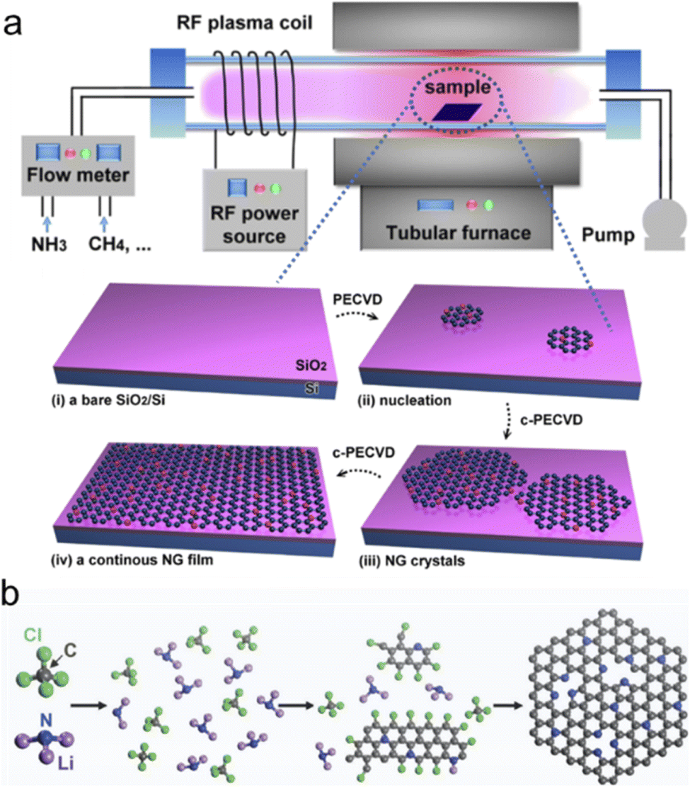
Besides these two typical bottom-up methods, electrochemical bottom-up synthesis or bottom-up self-assembly was also developed to synthesize NG, strictly speaking, N-doped graphene quantum dots or graphene nanoribbons.76 Tian et al. used o-phenylenediamine as the reactant in pure water as the electrolyte and applied a constant voltage of 500 V between two high-purity Pt sheets for more than 1 hour at 25 °C at a stirring rate of 1000 rpm. The colorless solution gradually turned yellow indicating the formation of NG with a size from 2 to 6 nm.77 Sinitskii and coworkers synthesized high-quality chevron-like N-doped graphene nanoribbons via Yamamoto coupling of molecular precursors containing nitrogen atoms followed by cyclodehydrogenation via the Scholl reaction.78
4. Electrocatalysis applications
4.1 Oxygen reduction reaction
The oxygen reduction reaction (ORR) is a critical reaction occurring at the cathode of fuel cells and metal-air batteries. Due to the sluggish reaction kinetics, precious Pt-based electrocatalysts are commonly used to boost the reaction, which usually accounts for almost half of the cost of fuel cells. To replace the commercial Pt-based electrocatalysts, many noble-metal-free materials have been developed, among which carbon-based materials are promising alternatives, especially N-doped carbon materials. As one of the N-doped carbon materials, NG not only holds the advantages of carbon materials (e.g., good electrical conductivity), but also possesses the unique features of graphene (e.g., high specific surface area and charge redistribution), which exhibits a highly promising prospect in the future.26The ORR is a multi-step reaction proceeding through either a direct 4e pathway or a two-step 2e pathway, which highly depends on the activity of the electrocatalyst. In an acidic medium, the possible reaction pathways are expressed as eqn (1)–(3), while those in alkaline solution are expressed as eqn (4)–(6).79
In an acidic medium,
| 4e pathway: O2+ 4H++4e− → 2H2O | (1) |
| 2e pathway: O2+ 2H++2e− → H2O2 | (2) |
| H2O2+ 2H++2e− → H2O | (3) |
In an alkaline medium,
| 4e pathway: O2+ 2H2O +4e− →4OH− | (4) |
| 2e pathway: O2+ H2O +2e− →HO2− + OH− | (5) |
| HO2− + H2O +2e− →3OH− | (6) |
A good selectivity of NG for the 4e reaction pathway is preferred in the application of fuel cells and metal-air batteries. For the reaction pathway in an alkaline medium, there are two different mechanisms, i.e., associative mechanism and dissociative mechanism, as shown in Fig. 5a.80 A density functional theory (DFT) study reveals that the associative mechanism (black line) on two surfaces (S1 and S2) of NG is more energetically favorable than the dissociative one (blue line), as shown in Fig. 5b and c. In S1 and S2, N atoms are separated by two C atoms and three C atoms, respectively, so S1 possesses a more concentrated N distribution than S2. The generation of OOH− is represented by the red line. The results show that the rate-determining step (RDS) in the associative mechanism is the removal of O(ads) species from the active site. And the formation energy of O(ads) on S1 is always lower (more exothermic) than that on S2, which is attributed to the higher local concentration of N atoms on S1 than that on S2.
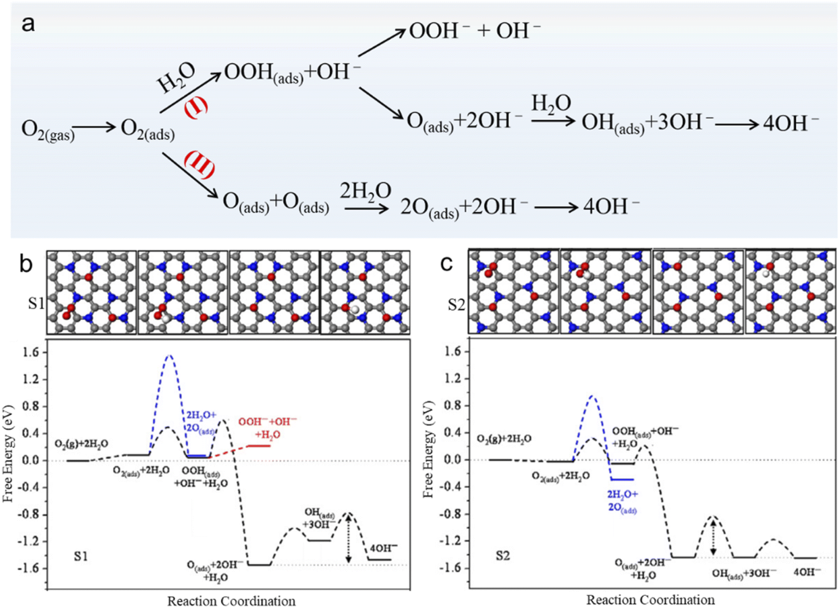 | ||
| Fig. 5 (a) ORR pathways on NG in alkaline solution, where (I) presents an associative mechanism and (II) is a dissociative mechanism. (b) Free energy diagram for O2 reduction on S1 and S2 under the conditions of 0.04 V and pH = 14. (c) Intermediate structures of the associative mechanism on S1 and S2. The gray, blue, red, and white spheres represent C, N, O, and H atoms, respectively. Reprinted with permission from ref. 80, Copyright©2012 Elsevier Inc. | ||
The real active sites in NG have been an attractive research topic due to contradictory opinions: carbon atoms adjacent to the N dopant, graphite-N or pyridine-N, or both. For example, Sidik and coworkers reported that substitutional N atoms from the graphite sheet edges are more active than those close to the edges.81 Niwa et al. also found that catalysts with more graphite N exhibit a higher ORR activity than those with more pyridine N.82 Huang et al. suggested that graphite N next to the zigzag edge enhances the O2 adsorption and the subsequent ORR process to two H2O with a small activation barrier of about 5 kcal mol−1, whereas the graphite N inside the graphene sheet does not contribute to ORR activity.37 Lai et al. synthesized different NG samples as shown in Fig. 6a by using different N-containing precursors and found that the limiting diffusion current (jL) and the onset potential (Eonset) are governed by graphitic-N and pyridinic-N, respectively (Fig. 6b).83 Jung's group found that graphitic N in particular enables improved ORR activity and becomes pyridinic N (stage IV) in the next transfer reaction of electrons and protons via the ring-opening of a cyclic C–N bond as shown in step (3a) in Fig. 6c.84 And the projected density of states (pDOS) and the orbital shape of N in stage (IV) are highly similar to those of typical pyridinic N. Recently, Guo et al. tactfully designed pyridinic N-dominated HOPG (pyri-HOPG) and graphitic N-dominated HOPG (grap-HOPG) as evidenced by Fig. 6d and proved that Lewis basic C atoms neighboring pyridinic N instead of pyridinic N themselves are active sites toward the ORR as illustrated by the polarization curves in Fig. 6e.85
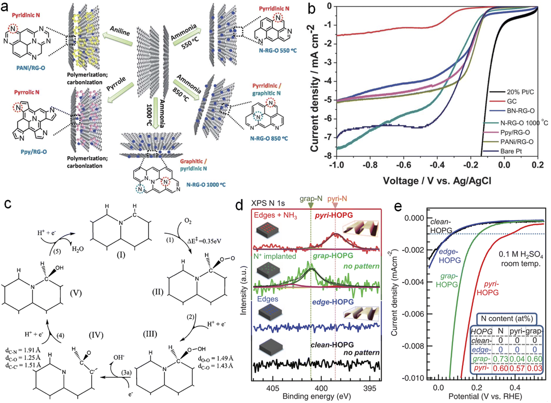 | ||
| Fig. 6 (a) Scheme for synthesis and (b) LSV curves of NG with different N species, (c) a proposed ORR catalytic cycle for graphitic-N doped graphene, (d) N 1s XPS spectra of model catalysts and (e) corresponding ORR polarization curves. (a and b) and (c) reprinted with permission from ref. 83 and 84, copyright© 2013 and 2011 The Royal Society of Chemistry, respectively. (d and e) Reprinted with permission from ref. 85. copyright© 2016 AAAS. | ||
Although there are unconsistent opinions on the function of different N species, there is no doubt that the introduction of N heteroatoms induces a positive charge density on an adjacent C atom, due to the high electronegativity of N.22 The redistribution of electrons facilitates the adsorption and subsequent reduction process. Zhang et al. theoretically calculated the atomic charge density and spin density of pristine graphene and NG by constructing the models of C46H18 and C45NH18.86 They pointed out that N-doping would promote the electrons to be easily excited from the valence band to the conduction band, because N doping introduces an unpaired electron and causes the localized distribution of molecule orbitals. Moreover, spin density is more important than atomic charge density in determining the catalytically active sites. Generally, carbon atoms with the highest spin density are the electrocatalytically active sites. These findings inspire the modulation of carbon-based materials toward a high-performance ORR, such as introducing other types of heteroatom or carbon defects to adjust the electronic structure or create more exposed active sites.
4.2 CO2 reduction reaction
Carbon neutrality has become a global goal, which is desired to achieve net-zero carbon dioxide (CO2) emissions. Enormous efforts have also been made by worldwide researchers. The electrochemical CO2RR is an effective approach to realize the conversion from CO2 to value-added chemical products.87 The CO2 molecule consisting of two linear C![[double bond, length as m-dash]](https://www.rsc.org/images/entities/char_e001.gif) O bonds is thermodynamically stable and chemically inert, due to a bond dissociation energy of 750 kJ mol−1, which is difficult to reduce.88 Moreover, the CO2RR becomes more challenging in an aqueous electrolyte, due to the competition of the hydrogen evolution reaction (HER) and the diversity of products. Generally, the CO2RR involves 2 to 18 electrons depending on different pathways as shown in Fig. 7. Therefore, electrocatalysts with high selectivity and activity toward CO2 are necessary.
O bonds is thermodynamically stable and chemically inert, due to a bond dissociation energy of 750 kJ mol−1, which is difficult to reduce.88 Moreover, the CO2RR becomes more challenging in an aqueous electrolyte, due to the competition of the hydrogen evolution reaction (HER) and the diversity of products. Generally, the CO2RR involves 2 to 18 electrons depending on different pathways as shown in Fig. 7. Therefore, electrocatalysts with high selectivity and activity toward CO2 are necessary.
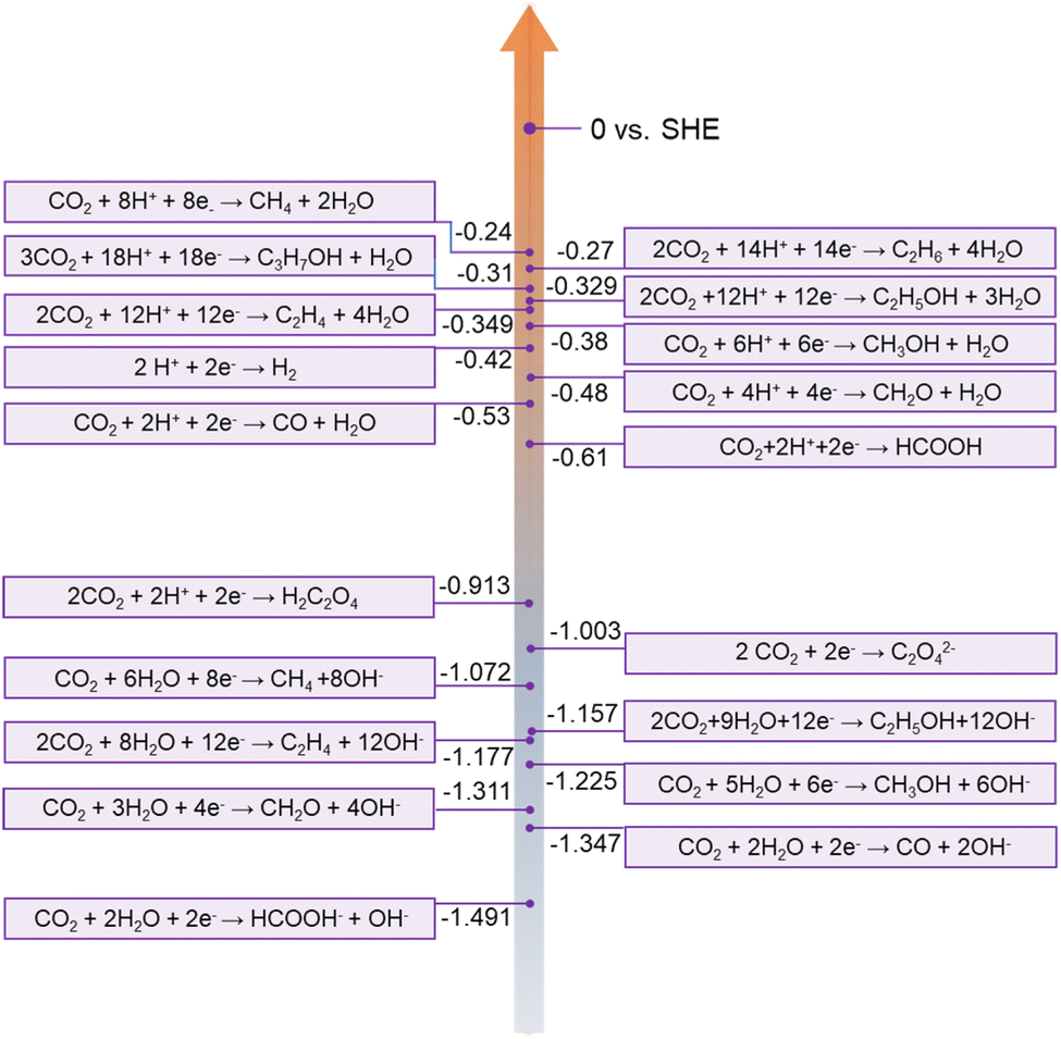 | ||
| Fig. 7 CO2RR at different standard potentials in aqueous solution at pH = 7.0, 1.0 atm, and 25°C. Reprinted with permission from ref. 26, copyright© 2019 The Royal Society of Chemistry. | ||
Inspired by the achievements of NG toward the ORR, researchers have also studied the electrocatalytic performance and mechanism of N-doped carbon materials. For example, Kumar et al. reported that N-doped carbon nanofibers (N-CNFs) are able to reduce CO2 to CO at a low overpotential of 0.17 V vs. SHE and exhibit exceptionally high current densities (∼13 times higher than that of bulk Ag) and a high FE of 98% for CO formation at −0.573 V vs. SHE.89 They proposed that the naturally oxidized carbon atoms with positive charge and later reduced C atoms adjacent to pyridinic-N in N-CNFs were responsible for the CO2RR. Sharma et al. also reported that the presence of graphitic and pyridinic nitrogen significantly decreases the overpotential and increases the selectivity towards the formation of CO.90
Ajayan's group conducted a series of experiments to improve the performance of the CO2RR. Firstly, they synthesized N-doped CNTs (N-CNTs) and obtained good CO2RR performance with an overpotential of −0.18 V and a selectivity of 80%.91 They thought that pyridinic N as a catalytic site possesses a low free energy for CO2 activation and a high barrier for hydrogen evolution. Moreover, by assembling NG to 3D foam, they improved the faradaic efficiency for CO production to ∼85% at a lower overpotential (−0.47 V) and stability for at least 5 h.92 DFT calculations show that the uphill free energy barrier comes from the first proton-coupled electron transfer step to form COOH* and drops dramatically upon introducing dangling N bonds (Fig. 8a & b). Triple-pyridinic N maximally lowers the barrier of the COOH* adsorption step followed by single pyridinic and graphitic N. Although COOH* adsorbing on pyrrolic N site is exergonic, the release of chemisorbed CO from pyrrolic-N is endothermic with an energy barrier of ∼0.6 eV (Fig. 8a). To increase the density of pyridinic N, they prepared nanometer-size N-doped graphene quantum dots (NGQDs) as shown in Fig. 8c and d. The NGQDs show a high total faradaic efficiency of up to 90% for the CO2RR, and the selectivity for ethylene (C2H4) and ethanol (EtOH and C2H5OH) conversions reaches 45% (Fig. 8e and f).93 The C2 and C3 product distribution and production rate for the CO2RR are comparable to those of Cu-based electrocatalysts. Theoretical calculations reveal that NGQDs can electrochemically convert CO2 to various hydrocarbons and oxygenates, including CH4, C2H4, and C2H5OH, which begin with effective reduction of CO2 to CO, promoted by enhanced binding between *COOH and NGQDs.94 It is found that water-assisted H shuttling significantly reduces the barrier for the generation of *CH2, the precursor for CH4, and the formation of C2 products critically depends on the coupling of C1 products, i.e.,*CH2 and CO.
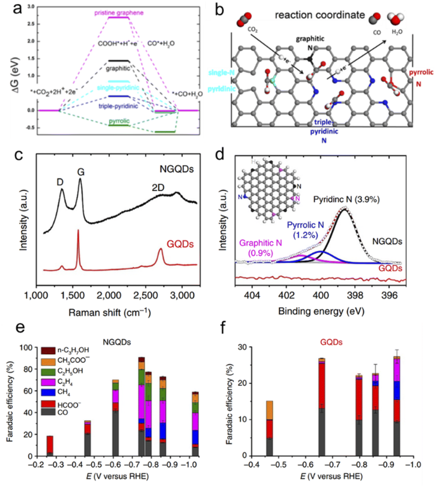 | ||
| Fig. 8 (a) Free energy diagram of electrochemical reduction of CO2 to CO on NG and (b) schematic of N configuration and the CO2 reduction pathway. (c) Raman spectrum of NGQDs as compared with that of pristine GQDs. (d) High-resolution N 1s spectrum for NGQDs, deconvoluted into three sub-peaks representing pyridinic, pyrrolic and graphitic N. The inset shows a scheme of NGQDs with zigzag edges and pyridinic (black), pyrrolic (blue) and graphitic (pink) N. (a and b) Reprinted with permission from ref. 92, copyright©2016 American Chemical Society. | ||
Recently, Liu's group synthesized a 3D N-doped graphene nanoribbon network (N-GRW) by using melamine and L-cysteine as reactants (Fig. 9a) and investigated its electrocatalytic activity toward the CO2RR.95 They found that only the current density of CO formation exhibits a linear regression with the concentration of pyridinic N as shown in Fig. 9b. To further verify the role of pyridinic N, they tuned the content of pyridinic N in N-GRW by a post-hydrogen treatment or phosphoric acid treatment. The results demonstrate that the activity of the CO2RR changes according to the content of pyridinic N. DFT calculations also reveal that the bonding between COOH and pyridinic N is in a suitable state (neither too strong nor too weak) as shown in Fig. 9c, which is conducive to the transformation of CO2 to *COOH and further to *CO. In contrast, Zheng's group selectively etched graphitic N and pyridinic N by using water steam and retained pyrrolic N in the N-doped carbon catalyst as shown in Fig. 9d.96 This steam-etched N-doped carbon with abundant pyrrolic N shows excellent CO2RR performance but low HER activity, exhibiting a high CO2RR selectivity (≈88%) toward the formation of CO under −0.5 V versus RHE. By virtue of DFT calculations, Liu found that pyrrolic N-doped graphene is the most efficient with an overpotential of 0.24 V among four types of N species (Fig. 9e).97 Moreover, the pyrrolic N reduces the free energy barrier of the RDS to form the key intermediate COOH and exclusively leads to HCOOH as the product.
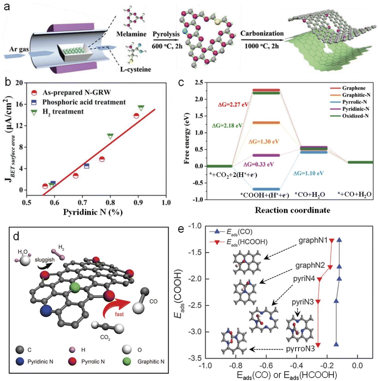 | ||
| Fig. 9 (a) Schematic diagram of the synthesis processes of N-GRW. (b) The relationship between the CO partial current density and the pyridinic N content in various N-GRW catalysts at 0.5 V versus RHE. (c) Free energy diagram of the CO2RR on various N-GRW catalysts. (d) Schematic illustration of the electrochemical CO2RR of N-doped carbon with abundant pyrrolic N and passivation for the HER. (a–c) and (d) Reprinted with permission from ref. 95 and 96, copyright© 2018 and 2017 WILEY-VCH, respectively. (e) Reprinted with permission from ref. 97, copyright © The Royal Society of Chemistry. | ||
5. Conclusion and outlook
In summary, we review the advances of NG with respect to fundamental properties, synthesis and electrocatalytic applications toward the ORR and CO2RR. As a promising alternative to noble meal catalysts, NG has exhibited promising potential to use in these two energy-conversion reactions. Because of the ideal 2D structure, it provides a good platform for exploring the underlying electrocatalytic mechanism behind the superior performance by both theoretical calculations and experiments. But it is still challenging to design and synthesize targeted NG with good selectivity and activity for the ORR or CO2RR. Developing advanced synthetic methods is an important precondition to guarantee a precise synthesis of NG with specific N species. In this regard, a bottom-up strategy holds a unique advantage, especially by coupling reaction between organic molecules with specific N species.98,99The complexity of N species in NG induces difficulty in uncovering the underlying electrocatalytic mechanism. Solid evidence on the electrocatalytic process and mechanism will be well revealed with the development of computational power and characterization techniques,100 such as in situ/operando Fourier Transform Infrared Spectroscopy (FTIR) and in situ/operando X-ray absorption spectroscopy (XAS).101,102 It is even necessary to establish an “in situ probing map” consisting of complementary aspects of electrocatalysts to track the dynamic process and identify the real active species systematically.102 Theoretically, machine learning is a powerful strategy to almost exhaustively screen NG with various N species and predict the desirable NG electrocatalyst.103–106 The combination of high-throughput screening of big data with purposeful experiments would open a new avenue for the development of NG used as an electrocatalyst.
Besides being a good candidate for electrocatalysts, NG also displays structural advantages to anchor single metal atoms due to the intrinsic defects of NG, thus forming high-performance single-atomic catalysts (SACs).107–109 For example, Sun's group fabricated single platinum atoms on NG nanosheets for hydrogen evolution by using the atomic layer deposition (ALD) technique, resulting in the utilization of nearly all the Pt atoms.110 Fei et al. synthesized a series of atomic 3d metals embedded in N-doped holey graphene and investigated the electrocatalytic performance toward the oxygen evolution reaction.111 The synthesis of SACs by using NG or N-doped carbon materials has become an important strategy.112 The flourishing of SACs would move forward the understanding of the catalytic mechanism and development of low-cost catalysts with high performance toward various catalytic reactions not only limited to the ORR and CO2RR.
Conflicts of interest
There are no conflicts to declare.Acknowledgements
The authors are grateful for financial support from the National Natural Science Foundation of China (52172058).References
- J. Fu, Z. P. Cano, M. G. Park, A. Yu, M. Fowler and Z. Chen, Adv. Mater., 2017, 29, 1604685 CrossRef PubMed.
- S. Wang and S. P. Jiang, Natl. Sci. Rev., 2017, 4, 163–166 CrossRef CAS.
- R. Ma, G. Lin, Y. Zhou, Q. Liu, T. Zhang, G. Shan, M. Yang and J. Wang, npj Comput. Mater., 2019, 5, 78 CrossRef.
- L. An, Y. Hu, J. Li, J. Zhu, M. Sun, B. Huang, P. Xi and C.-H. Yan, Adv. Mater., 2022, 34, 2202874 CrossRef CAS PubMed.
- G. Wang, J. Chen, Y. Ding, P. Cai, L. Yi, Y. Li, C. Tu, Y. Hou, Z. Wen and L. Dai, Chem. Soc. Rev., 2021, 50, 4993–5061 RSC.
- J. Wu, Y. Huang, W. Ye and Y. Li, Adv. Sci., 2017, 4, 1700194 CrossRef PubMed.
- J. Yin, Z. Yin, J. Jin, M. Sun, B. Huang, H. Lin, Z. Ma, M. Muzzio, M. Shen, C. Yu, H. Zhang, Y. Peng, P. Xi, C.-H. Yan and S. Sun, J. Am. Chem. Soc., 2021, 143, 15335–15343 CrossRef CAS PubMed.
- Y. P. Zhu, C. Guo, Y. Zheng and S.-Z. Qiao, Acc. Chem. Res., 2017, 50, 915–923 CrossRef CAS PubMed.
- H. Jing, P. Zhu, X. Zheng, Z. Zhang, D. Wang and Y. Li, Advanced Powder Materials, 2022, 1, 100013 CrossRef.
- K. S. Novoselov, V. I. Fal′ko, L. Colombo, P. R. Gellert, M. G. Schwab and K. Kim, Nature, 2012, 490, 192–200 CrossRef CAS PubMed.
- H. Tao, Y. Gao, N. Talreja, F. Guo, J. Texter, C. Yan and Z. Sun, J. Mater. Chem. A, 2017, 5, 7257–7284 RSC.
- X. Zhang, A. Chen, L. Chen and Z. Zhou, Adv. Energy Mater., 2022, 12, 2003841 CrossRef CAS.
- X. Zhan, C. Si, J. Zhou and Z. Sun, Nanoscale Horiz., 2020, 5, 235–258 RSC.
- R. Qin, G. Shan, M. Hu and W. Huang, Mater. Today Phys., 2021, 21, 100527 CrossRef CAS.
- H. Li, J. Wu, Z. Yin and H. Zhang, Acc. Chem. Res., 2014, 47, 1067–1075 CrossRef CAS PubMed.
- Y. Xu, B. Li, S. Zheng, P. Wu, J. Zhan, H. Xue, Q. Xu and H. Pang, J. Mater. Chem. A, 2018, 6, 22070–22076 RSC.
- Y. Yan, J. Gong, J. Chen, Z. Zeng, W. Huang, K. Pu, J. Liu and P. Chen, Adv. Mater., 2019, 31, 1808283 CrossRef PubMed.
- S. Dutta and S. K. Pati, J. Mater. Chem., 2010, 20, 8207–8223 RSC.
- J. Bai, X. Zhong, S. Jiang, Y. Huang and X. Duan, Nat. Nanotechnol., 2010, 5, 190–194 CrossRef CAS PubMed.
- Y. Cao, V. Fatemi, S. Fang, K. Watanabe, T. Taniguchi, E. Kaxiras and P. Jarillo-Herrero, Nature, 2018, 556, 43–50 CrossRef CAS PubMed.
- R. Ma, Y. Zhou, H. Bi, M. Yang, J. Wang, Q. Liu and F. Huang, Prog. Mater. Sci., 2020, 113, 100665 CrossRef CAS.
- Z. Zhao, M. Li, L. Zhang, L. Dai and Z. Xia, Adv. Mater., 2015, 27, 6834–6840 CrossRef CAS PubMed.
- M. Inagaki, M. Toyoda, Y. Soneda and T. Morishita, Carbon, 2018, 132, 104–140 CrossRef CAS.
- K. Gong, F. Du, Z. Xia, M. Durstock and L. Dai, Science, 2009, 323, 760–764 CrossRef CAS PubMed.
- Y. Shao, Z. Jiang, Q. Zhang and J. Guan, ChemSusChem, 2019, 12, 2133–2146 CrossRef CAS PubMed.
- L. Qu, Y. Liu, J.-B. Baek and L. Dai, ACS Nano, 2010, 4, 1321–1326 CrossRef CAS PubMed.
- H. Cui, Y. Guo, L. Guo, L. Wang, Z. Zhou and Z. Peng, J. Mater. Chem. A, 2018, 6, 18782–18793 RSC.
- X. Duan, J. Xu, Z. Wei, J. Ma, S. Guo, S. Wang, H. Liu and S. Dou, Adv. Mater., 2017, 29, 1701784 CrossRef.
- D. M. Fernandes, A. F. Peixoto and C. Freire, Dalton Trans., 2019, 48, 13508–13528 RSC.
- S. Casolo, R. Martinazzo and G. F. Tantardini, J. Phys. Chem. C, 2011, 115, 3250–3256 CrossRef CAS.
- L. Zhao, R. He, K. T. Rim, T. Schiros, K. S. Kim, H. Zhou, C. Gutiérrez, S. P. Chockalingam, C. J. Arguello, L. Pálová, D. Nordlund, M. S. Hybertsen, D. R. Reichman, T. F. Heinz, P. Kim, A. Pinczuk, G. W. Flynn and A. N. Pasupathy, Science, 2011, 333, 999–1003 CrossRef CAS PubMed.
- T. Kondo, S. Casolo, T. Suzuki, T. Shikano, M. Sakurai, Y. Harada, M. Saito, M. Oshima, M. I. Trioni, G. F. Tantardini and J. Nakamura, Phys. Rev. B, 2012, 86, 035436 CrossRef.
- M. Zhang and L. Dai, Nano Energy, 2012, 1, 514–517 CrossRef CAS.
- A. Lherbier, A. R. Botello-Méndez and J.-C. Charlier, Nano Lett., 2013, 13, 1446–1450 CrossRef CAS.
- R. Lv, Q. Li, A. R. Botello-Méndez, T. Hayashi, B. Wang, A. Berkdemir, Q. Hao, A. L. Elías, R. Cruz-Silva, H. R. Gutiérrez, Y. A. Kim, H. Muramatsu, J. Zhu, M. Endo, H. Terrones, J.-C. Charlier, M. Pan and M. Terrones, Sci. Rep., 2012, 2, 586 CrossRef PubMed.
- X. Wang, Z. Hou, T. Ikeda, S.-F. Huang, K. Terakura, M. Boero, M. Oshima, M.-a. Kakimoto and S. Miyata, Phys. Rev. B, 2011, 84, 245434 CrossRef.
- S.-F. Huang, K. Terakura, T. Ozaki, T. Ikeda, M. Boero, M. Oshima, J.-I. Ozaki and S. Miyata, Phys. Rev. B, 2009, 80, 235410 CrossRef.
- X. Wang, Z. Hou, T. Ikeda, M. Oshima, M.-A. Kakimoto and K. Terakura, J. Phys. Chem. A, 2013, 117, 579–589 CrossRef CAS PubMed.
- Z. Li, R. Ma, Q. Ju, Q. Liu, L. Liu, Y. Zhu, M. Yang and J. Wang, Innovation, 2022, 3, 100268 CAS.
- J. Zhong, J.-J. Deng, B.-H. Mao, T. Xie, X.-H. Sun, Z.-G. Mou, C.-H. Hong, P. Yang and S.-D. Wang, Carbon, 2012, 50, 335–338 CrossRef CAS.
- R. S. Edwards and K. S. Coleman, Nanoscale, 2013, 5, 38–51 RSC.
- J. M. Tour, Chem. Mater., 2014, 26, 163–171 CrossRef CAS.
- X. Li, H. Wang, J. T. Robinson, H. Sanchez, G. Diankov and H. Dai, J. Am. Chem. Soc., 2009, 131, 15939–15944 CrossRef CAS PubMed.
- G. Lemes, D. Sebastián, E. Pastor and M. J. Lázaro, J. Power Sources, 2019, 438, 227036 CrossRef CAS.
- L. Sun, L. Wang, C. Tian, T. Tan, Y. Xie, K. Shi, M. Li and H. Fu, RSC Adv., 2012, 2, 4498–4506 RSC.
- D. Voiry, J. Yang, J. Kupferberg, R. Fullon, C. Lee, H. Y. Jeong, H. S. Shin and M. Chhowalla, Science, 2016, 353, 1413–1416 CrossRef CAS PubMed.
- S. P. Economopoulos, G. Rotas, Y. Miyata, H. Shinohara and N. Tagmatarchis, ACS Nano, 2010, 4, 7499–7507 CrossRef CAS PubMed.
- R. Jakhar, J. E. Yap and R. Joshi, Carbon, 2020, 170, 277–293 CrossRef CAS.
- J. Sun, W. Wang and Q. Yue, Materials, 2016, 9, 231 CrossRef PubMed.
- C. Wang, X. Han, P. Xu, X. Zhang, Y. Du, S. Hu, J. Wang and X. Wang, Appl. Phys. Lett., 2011, 98, 072906 CrossRef.
- Y. Xin, J. G. Liu, X. Jie, W. Liu, F. Liu, Y. Yin, J. Gu and Z. Zou, Electrochim. Acta, 2012, 60, 354–358 CrossRef CAS.
- Y.-H. Lee, K.-H. Chang and C.-C. Hu, J. Power Sources, 2013, 227, 300–308 CrossRef CAS.
- A. Dey, A. Chroneos, N. S. J. Braithwaite, R. P. Gandhiraman and S. Krishnamurthy, Appl. Phys. Rev., 2016, 3, 021301 Search PubMed.
- I. Bertóti, M. Mohai and K. László, Carbon, 2015, 84, 185–196 CrossRef.
- Y. Wang, Y. Shao, D. W. Matson, J. Li and Y. Lin, ACS Nano, 2010, 4, 1790–1798 CrossRef CAS PubMed.
- H. M. Jeong, J. W. Lee, W. H. Shin, Y. J. Choi, H. J. Shin, J. K. Kang and J. W. Choi, Nano Lett., 2011, 11, 2472–2477 CrossRef CAS.
- S. Sakulsermsuk, P. Singjai and C. Chaiwong, Diamond Relat. Mater., 2016, 70, 211–218 CrossRef CAS.
- K. S. Subrahmanyam, L. S. Panchakarla, A. Govindaraj and C. N. R. Rao, J. Phys. Chem. C, 2009, 113, 4257–4259 CrossRef CAS.
- N. Li, Z. Wang, K. Zhao, Z. Shi, Z. Gu and S. Xu, Carbon, 2010, 48, 255–259 CrossRef CAS.
- W. Qian, X. Cui, R. Hao, Y. Hou and Z. Zhang, ACS Appl. Mater. Interfaces, 2011, 3, 2259–2264 CrossRef CAS PubMed.
- I. Choi, H. Y. Jeong, D. Y. Jung, M. Byun, C.-G. Choi, B. H. Hong, S.-Y. Choi and K. J. Lee, ACS Nano, 2014, 8, 7671–7677 CrossRef CAS PubMed.
- Y. Zhang, B. Cao, B. Zhang, X. Qi and C. Pan, Thin Solid Films, 2012, 520, 6850–6855 CrossRef CAS.
- Y. Zhang, L. Zhang and C. Zhou, Acc. Chem. Res., 2013, 46, 2329–2339 CrossRef CAS PubMed.
- A. Cabrero-Vilatela, R. S. Weatherup, P. Braeuninger-Weimer, S. Caneva and S. Hofmann, Nanoscale, 2016, 8, 2149–2158 RSC.
- D. Wei, L. Peng, M. Li, H. Mao, T. Niu, C. Han, W. Chen and A. T. S. Wee, ACS Nano, 2015, 9, 164–171 CrossRef CAS PubMed.
- Y. Xue, B. Wu, L. Jiang, Y. Guo, L. Huang, J. Chen, J. Tan, D. Geng, B. Luo, W. Hu, G. Yu and Y. Liu, J. Am. Chem. Soc., 2012, 134, 11060–11063 CrossRef CAS PubMed.
- G. Imamura and K. Saiki, J. Phys. Chem. C, 2011, 115, 10000–10005 CrossRef CAS.
- G. Imamura, C. W. Chang, Y. Nabae, M.-a. Kakimoto, S. Miyata and K. Saiki, J. Phys. Chem. C, 2012, 116, 16305–16310 CrossRef CAS.
- J. Zhang, J. Li, Z. Wang, X. Wang, W. Feng, W. Zheng, W. Cao and P. Hu, Chem. Mater., 2014, 26, 2460–2466 CrossRef CAS.
- Y. Ito, C. Christodoulou, M. V. Nardi, N. Koch, H. Sachdev and K. Müllen, ACS Nano, 2014, 8, 3337–3346 CrossRef CAS.
- X. Lü, J. Wu, T. Lin, D. Wan, F. Huang, X. Xie and M. Jiang, J. Mater. Chem., 2011, 21, 10685–10689 RSC.
- D. Deng, X. Pan, L. Yu, Y. Cui, Y. Jiang, J. Qi, W.-X. Li, Q. Fu, X. Ma, Q. Xue, G. Sun and X. Bao, Chem. Mater., 2011, 23, 1188–1193 CrossRef CAS.
- D. Geng, Y. Hu, Y. Li, R. Li and X. Sun, Electrochem. Commun., 2012, 22, 65–68 CrossRef CAS.
- R. Ma, X. Ren, B. Y. Xia, Y. Zhou, C. Sun, Q. Liu, J. Liu and J. Wang, Nano Res., 2016, 9, 808–819 CrossRef CAS.
- R. Ma, Y. Zhou, P. Li, Y. Chen, J. Wang and Q. Liu, Electrochim. Acta, 2016, 216, 347–354 CrossRef CAS.
- C. Bronner, S. Stremlau, M. Gille, F. Brausse, A. Haase, S. Hecht and P. Tegeder, Angew. Chem., Int. Ed., 2013, 52, 4422–4425 CrossRef CAS.
- L. Tian, S. Yang, Y. Yang, J. Li, Y. Deng, S. Tian, P. He, G. Ding, X. Xie and Z. Wang, RSC Adv., 2016, 6, 82648–82653 RSC.
- T. H. Vo, M. Shekhirev, D. A. Kunkel, F. Orange, M. J. F. Guinel, A. Enders and A. Sinitskii, Chem. Commun., 2014, 50, 4172–4174 RSC.
- Y. Zheng, Y. Jiao, M. Jaroniec, Y. Jin and S. Z. Qiao, Small, 2012, 8, 3550–3566 CrossRef CAS PubMed.
- L. Yu, X. Pan, X. Cao, P. Hu and X. Bao, J. Catal., 2011, 282, 183–190 CrossRef CAS.
- R. A. Sidik, A. B. Anderson, N. P. Subramanian, S. P. Kumaraguru and B. N. Popov, J. Phys. Chem. B, 2006, 110, 1787–1793 CrossRef CAS PubMed.
- H. Niwa, K. Horiba, Y. Harada, M. Oshima, T. Ikeda, K. Terakura, J.-i. Ozaki and S. Miyata, J. Power Sources, 2009, 187, 93–97 CrossRef CAS.
- L. Lai, J. R. Potts, D. Zhan, L. Wang, C. K. Poh, C. Tang, H. Gong, Z. Shen, J. Lin and R. S. Ruoff, Energy Environ. Sci., 2012, 5, 7936–7942 RSC.
- H. Kim, K. Lee, S. I. Woo and Y. Jung, Phys. Chem. Chem. Phys., 2011, 13, 17505–17510 RSC.
- D. Guo, R. Shibuya, C. Akiba, S. Saji, T. Kondo and J. Nakamura, Science, 2016, 351, 361–365 CrossRef CAS PubMed.
- L. Zhang and Z. Xia, J. Phys. Chem. C, 2011, 115, 11170–11176 CrossRef CAS.
- Z. Sun, T. Ma, H. Tao, Q. Fan and B. Han, Chem, 2017, 3, 560–587 CAS.
- Q. Lu and F. Jiao, Nano Energy, 2016, 29, 439–456 CrossRef CAS.
- B. Kumar, M. Asadi, D. Pisasale, S. Sinha-Ray, B. A. Rosen, R. Haasch, J. Abiade, A. L. Yarin and A. Salehi-Khojin, Nat. Commun., 2013, 4, 2819 CrossRef.
- P. P. Sharma, J. Wu, R. M. Yadav, M. Liu, C. J. Wright, C. S. Tiwary, B. I. Yakobson, J. Lou, P. M. Ajayan and X.-D. Zhou, Angew. Chem., Int. Ed., 2015, 54, 13701–13705 CrossRef CAS PubMed.
- J. Wu, R. M. Yadav, M. Liu, P. P. Sharma, C. S. Tiwary, L. Ma, X. Zou, X.-D. Zhou, B. I. Yakobson, J. Lou and P. M. Ajayan, ACS Nano, 2015, 9, 5364–5371 CrossRef CAS PubMed.
- J. Wu, M. Liu, P. P. Sharma, R. M. Yadav, L. Ma, Y. Yang, X. Zou, X.-D. Zhou, R. Vajtai, B. I. Yakobson, J. Lou and P. M. Ajayan, Nano Lett., 2016, 16, 466–470 CrossRef CAS PubMed.
- J. Wu, S. Ma, J. Sun, J. I. Gold, C. Tiwary, B. Kim, L. Zhu, N. Chopra, I. N. Odeh, R. Vajtai, A. Z. Yu, R. Luo, J. Lou, G. Ding, P. J. A. Kenis and P. M. Ajayan, Nat. Commun., 2016, 7, 13869 CrossRef CAS PubMed.
- X. Zou, M. Liu, J. Wu, P. M. Ajayan, J. Li, B. Liu and B. I. Yakobson, ACS Catal., 2017, 7, 6245–6250 CrossRef CAS.
- S. Liu, H. Yang, X. Huang, L. Liu, W. Cai, J. Gao, X. Li, T. Zhang, Y. Huang and B. Liu, Adv. Funct. Mater., 2018, 28, 1800499 CrossRef.
- X. Cui, Z. Pan, L. Zhang, H. Peng and G. Zheng, Adv. Energy Mater., 2017, 7, 1701456 CrossRef.
- Y. Liu, J. Zhao and Q. Cai, Phys. Chem. Chem. Phys., 2016, 18, 5491–5498 RSC.
- A. Jolly, D. Miao, M. Daigle and J.-F. Morin, Angew. Chem., Int. Ed., 2020, 59, 4624–4633 CrossRef CAS PubMed.
- J. Cai, P. Ruffieux, R. Jaafar, M. Bieri, T. Braun, S. Blankenburg, M. Muoth, A. P. Seitsonen, M. Saleh, X. Feng, K. Müllen and R. Fasel, Nature, 2010, 466, 470–473 CrossRef CAS PubMed.
- X. Li, S. Wang, L. Li, Y. Sun and Y. Xie, J. Am. Chem. Soc., 2020, 142, 9567–9581 CAS.
- J. Timoshenko and B. Roldan Cuenya, Chem. Rev., 2021, 121, 882–961 CrossRef CAS PubMed.
- Y. Zhu, J. Wang, H. Chu, Y.-C. Chu and H. M. Chen, ACS Energy Lett., 2020, 5, 1281–1291 CrossRef CAS.
- N. Zhang, B. Yang, K. Liu, H. Li, G. Chen, X. Qiu, W. Li, J. Hu, J. Fu, Y. Jiang, M. Liu and J. Ye, Small Methods, 2021, 5, 2100987 CrossRef CAS.
- J. Liu, W. Luo, L. Wang, J. Zhang, X.-Z. Fu and J.-L. Luo, Adv. Funct. Mater., 2022, 32, 2110748 CrossRef CAS.
- S. Xu and E. A. Carter, Chem. Rev., 2019, 119, 6631–6669 CrossRef CAS.
- X. Yuan, L. Li, Z. Shi, H. Liang, S. Li and Z. Qiao, Advanced Powder Materials, 2022, 1, 100026 CrossRef.
- L. Zhang, Y. Ren, W. Liu, A. Wang and T. Zhang, Natl. Sci. Rev., 2018, 5, 653–672 CrossRef CAS.
- T. Zheng, K. Jiang, N. Ta, Y. Hu, J. Zeng, J. Liu and H. Wang, Joule, 2019, 3, 265–278 CrossRef CAS.
- L. Yu, F. Li, J. Zhao and Z. Chen, Advanced Powder Materials, 2022, 1, 100031 CrossRef.
- N. Cheng, S. Stambula, D. Wang, M. N. Banis, J. Liu, A. Riese, B. Xiao, R. Li, T.-K. Sham, L.-M. Liu, G. A. Botton and X. Sun, Nat. Commun., 2016, 7, 13638 CrossRef CAS PubMed.
- H. Fei, J. Dong, Y. Feng, C. S. Allen, C. Wan, B. Volosskiy, M. Li, Z. Zhao, Y. Wang, H. Sun, P. An, W. Chen, Z. Guo, C. Lee, D. Chen, I. Shakir, M. Liu, T. Hu, Y. Li, A. I. Kirkland, X. Duan and Y. Huang, Nat. Catal., 2018, 1, 63–72 CrossRef CAS.
- J. Ma, X. Li, Y. Li, G. Jiao, H. Su, D. Xiao, S. Zhai and R. Sun, Advanced Powder Materials, 2022, 1, 100058 CrossRef.
| This journal is © The Royal Society of Chemistry 2022 |