
 Open Access Article
 This Open Access Article is licensed under a
 Creative Commons Attribution 3.0 Unported Licence
A new approach in the one-step synthesis of α-MnO2via a modified solution combustion procedure
Mahsa Mohammadi
Moqaddam
,
Mostafa
Mirjalili
 *,
Jalil Vahdati
Khaki
and
Sahar Mollazadeh
Beidokhti
*,
Jalil Vahdati
Khaki
and
Sahar Mollazadeh
Beidokhti
Department of Materials and Metallurgical Engineering, Faculty of Engineering, Ferdowsi University of Mashhad, Mashhad 91775-1111, Iran. E-mail: mirjalili@um.ac.ir
First published on 9th August 2022
Abstract
Manganese oxides were synthesized systematically via the solution combustion procedure using two kinds of fuels, namely glycine and urea. The influences of the type of fuel and the fuel ratio were deeply investigated to explain the phase evolution and morphology of the product. The synthesized nanostructured powder was characterized by X-ray diffraction, particle size analysis, and FESEM. Furthermore, the thermodynamic aspects of all the synthesis reactions were studied by the calculation of the adiabatic temperature. Various manganese oxides, such as MnO, Mn3O4, Mn2O3, and MnO2, were obtained by varying the fuel ratio from 0.15 to 2. It was found that decreasing the fuel ratio promoted the formation of MnO2 by declining the combustion temperature and reductive conditions of the system. However, α-MnO2 could be simply achieved by adding KNO3 in a modified solution combustion process under fuel-lean conditions. Further heat treatment of the product was found to increase the crystallinity of the α-MnO2 nanoparticles.
1 Introduction
For decades, manganese oxides (MnO, Mn3O4, Mn2O3, and MnO2) have been considered as promising materials due to their wide range of technological applications, including as catalysts, electrochemical materials, ion-exchange materials, and high-density magnetic storage media. Among the various types of manganese oxides, nanostructured manganese dioxide (MnO2) exists in various polymorph forms, such as α-, β-, γ-, δ-, ε-, and λ-MnO2, in which all the crystalline structures are composed of octahedral MnO6 building blocks,1 with oxygen atoms at the corners of the octahedra and Mn atoms at the center. Further, for the α-MnO2 structure, its double chains of edge-sharing MnO6 octahedra form 2 × 2 square-shaped open tunnels with dimensions of 4.6 × 4.6 Å.2It has been recently reported that the catalytic activity of MnO2 is related to its structural features. Different polymorphs of MnO2 were investigated as an electrocatalyst,3,4 and α-MnO2 exhibited a great catalytic activity. A similar sequence of the ORR catalyst activity was found in MnO2 with different crystal forms: β-MnO2 < λ-MnO2 < γ-MnO2 < α-MnO2 ≈ δ-MnO2.3 Here, the α-MnO2 (Mn8O16) type often contain cations with 1+ or 2+ charges that are located within the manganese oxide tunnels where the Mn cations possess mixed 3+ and 4+ oxidation states.5 In general, the α-MnO2 oxide forms in the isostructural series with a general formula, whereby α-MnO2 can be formed only in the presence of a large ion, such as K+, and the general formula is A2−yB8−zX16 (A represents large ions, such as Ba2+, Pb2+ or K+; B is Mn4+, Fe3+, or Mn2+; X is O2− or OH−; and 0.8 < y < 1.3 and 0.1 < z < 0.5). The most common form is KxMn8O16 (cryptomelane); however, the 2 × 2 tunnels of α-MnO2 can reversibly host various other cations, such as Ag+, NH4+, and Na+.6–8 α-MnO2 has been used in lithium-ion batteries, supercapacitors, and catalysts because of its high theoretical capacitance (1370 F.g−1), low toxicity, low cost, natural abundance, and environmental friendliness.
Potassium-containing cryptomelane (KxMn8O16) can be synthesized by a variety of methods, including hydrothermal9,10 and sol–gel11,12 techniques. Among these mentioned synthesis procedures, the hydrothermal method has been mostly used to synthesize α-MnO2. Moreover, redox sol–gel and acid digestion have been employed to synthesize K1.2Mn8O16 and K1.3Mn8O16 for electrocatalytic application, which showed S-shaped discharge curves with voltage plateaus of 3.0 V and 2.45 V.13 Despite their relatively high plateau voltages, they showed modest initial discharge capacities of 160 and 188 mA h g−1, when examined at 0.1 mA cm−2 and 50 mA g−1, respectively.14 In another study, cryptomelane-type tunnel-structured manganese dioxides (KxMn8O16) with different K+ amounts were prepared by a hydrothermal redox reaction. The K+ content of KxMn8O16 was controlled by altering the reactant ratio of K2SO4/(NH4)2SO4. The catalytic behavior of KxMn8O16 with different amounts of K+ was evaluated using the cyclic voltammetry (CV) technique and the results suggested that KxMn8O16 with a lower K+ content (x = 0.0, 0.32) showed a higher delivered capacity, improved capacity retention, higher discharge voltage, and higher lithium-ion diffusion coefficient (DLi+) than high K+ (x = 0.51, 0.70, 0.75)-containing KxMn8O16.9 The disadvantage of these methods is that they require high temperatures, expensive precursors, and long processing times for the synthesis, which also often need special and expensive equipment.
Solution combustion synthesis (SCS) is a combustion-based process that involves converting fuel and an oxidant into a foamy crystalline material through rapid exothermic reactions. Research on SCS has attracted extensive attention in recent years, due to its various advantages, including its ability to reach high temperatures, quick heating, short reaction times, and the formation of pure products.15–18
In the present study, α-MnO2 powders were synthesized through a solution combustion synthesis method. Considering the fact that MnO2 is stable at low temperatures while the other forms of manganese oxide are stable at high temperatures, the synthesis of MnO2 was challenging by the SCS method, as this is a high-temperature process. Moreover, attaining α-MnO2 makes the process more complicated. Thus, various parameters, such as adiabatic temperature, adding a stabilizer, and varying the fuel/oxidizer ratio and the type of fuel, were controlled in order to produce this unique structure. More importantly, our study highlights the improvement of the physicochemical properties of the as-synthesized α-MnO2 powders by modifying the morphology and particle size. Furthermore, the impact of K+ on stabilizing α-MnO2 was investigated through the SCS process.
2 Experimental procedure
2.1 Synthesis of α-MnO2
Manganese(II) nitrate tetrahydrate (Mn (NO3)2·4H2O > 99%, Merck, Germany), potassium nitrate (KNO3 > 99%, Merck, Germany)m and urea (CH4N2O > 99%, Neutron, Iran) were utilized as precursors.The synthesis procedure was carried out according to the following five systems.
Stoichiometric system using glycine and urea as fuels with the ratio of the total reducing valences to total oxidizing valences being unity (φ = 1) for the production of MnO2. This system was applied to study the effect of the fuel type on the physicochemical properties of the final product (samples G-1 and U-1).
Non-stoichiometric system with various φ ratios (φ = 0.15, 0.25, 0.5, 1, and 2) using glycine: This system was used to investigate the effect of the φ value on the physicochemical properties of the final product (samples G-0.15, G-0.25, G-0.5, G-1, and G-2).
Non-stoichiometric system with various φ ratios (φ = 0.15, 0.25, 0.4, 0.5, 0.6, 0.8, 1, and 2) using urea: This system was used to investigate the effect of the φ value on the physicochemical properties of the final product (samples U-0.15, U-0.25, U-0.4, U-0.5, U-0.6, U-0.8, U-1, and U-2).
System using urea (φ = 0.25) with KCl as the stabilizer of α-MnO2 with various K/Mn ratios of 0.006, 0.030, 0.059, and 0.259: This system was used to study the effect of KCl on the physicochemical properties of the final product (samples U–KCl-0.006, U–KCl-0.030, U–KCl-0.059, and U–KCl-0.295).
System using urea with KNO3 as the stabilizer of α-MnO2 with various φ ratios (φ = 0.8, 0.85, 0.9, and 1): This system was used to investigate the effect of KNO3 on the physicochemical properties of the final product (samples U–K-0.8, U–K-0.85, U–K-0.9, and U–K-1). For this purpose, the mass ratio of KNO3 to Mn(NO3)2·4H2O was considered to be 0.8. The as-synthesized sample U–K-0.8 was also heat treated at 380 °C for 48 h to investigate the effect of annealing on the crystallinity of the nanoparticles (sample U–K-0.8-Ht).
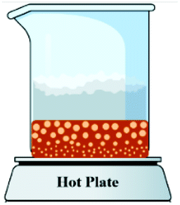
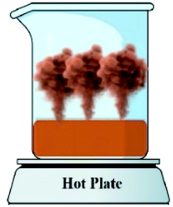
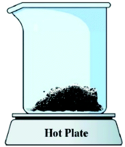
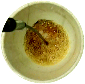
Table 1 presents the balanced reactions between the nitrates, fuels, and stabilizer at various φ values (system 1, 2, 3, 4, and 5). In the synthesis procedure, the desired amounts of precursors were first dissolved in 10 mL of deionized water according to the equations listed in Table 1. The solution was then magnetically stirred to achieve a homogenous solution. The obtained clear solution was poured into an alumina crucible and placed on a hotplate. The solution was heated until the extra water was evaporated and a gel formed. In this step, the temperature increased and once it exceeded the ignition temperature of the reaction, combustion occurred. Then the combustion reaction was ignited in a flaming manner, resulting in the formation of crystalline nanopowders. Afterwards, the product was filtered and rinsed with deionized water several times. Finally, the powder was placed in an oven and dried at 60 °C for 1 h.
| System | Sample code | Chemical reaction | φ |
|---|---|---|---|
| 1 | G-1 | Mn(NO3)2·4H2O + 0.889C2H5NO2 = MnO2 + 1.778 CO2 (g) + 6.222H2O (g) + 1.444 N2 (g) | 1 |
| U-1 | Mn(NO3)2·4H2O + 1.333 CH4N2O = MnO2 + 1.333 CO2 (g) + 6.667H2O (g) + 2.333 N2 (g) | 1 | |
| 2 | G-0.15 | Mn(NO3)2·4H2O + 0.133C2H5NO2 = 0.150 MnO2 + 0.266 CO2 (g) + 0.216 N2 (g) + 0.934H2O (g) + 0.850 Mn(NO3)2·4H2O | 0.15 |
| G-0.25 | Mn(NO3)2·4H2O + 0.222C2H5NO2 = 0.250 MnO2 + 0.444 CO2 (g) + 1.555H2O (g) + 0.361 N2 (g) + 0.750 Mn(NO3)2·4H2O | 0.25 | |
| G-0.5 | Mn(NO3)2·4H2O + 0.444C2H5NO2 = 0.500 MnO2 + 0.888 CO2 (g) + 3.111H2O (g) + 0.722 N2 (g) + 0.500 Mn(NO3)2·4H2O | 0.5 | |
| G-1 | Mn(NO3)2·4H2O + 0.889C2H5NO2 = MnO2 + 1.778 CO2 (g) + 6.222H2O (g) + 1.444 N2 (g) | 1 | |
| G-2 | Mn(NO3)2·4H2O + 1.778C2H5NO2 = MnO2 + 1.778 CO2 (g) + 6.222H2O (g) + 1.444 N2 (g) + 0.889C2H5NO2 | 2 | |
| 3 | U-0.15 | Mn(NO3)2·4H2O + 0.200 CH4N2O = 0.150 MnO2 + 0.200 CO2 (g) + 0.350 N2 (g) + H2O (g) + 0.850 Mn(NO3)2·4H2O | 0.15 |
| U-0.25 | Mn(NO3)2·4H2O + 0.333 CH4N2O = 0.250 MnO2 + 0.333 CO2 (g) + 0.583 N2 (g) + 1.667H2O (g) + 0.750 Mn(NO3)2·4H2O | 0.25 | |
| U-0.4 | Mn(NO3)2·4H2O + 0.533 CH4N2O = 0.400 MnO2 + 0.533 CO2 (g) + 2.667H2O (g) + 0.933 N2 (g) + 0.600 Mn(NO3)2·4H2O | 0.4 | |
| U-0.5 | Mn(NO3)2·4H2O + 0.667 CH4N2O = 0.500 MnO2 + 0.667 CO2 (g) + 3.333H2O (g) + 1.166 N2 (g) + 0.500 Mn(NO3)2·4H2O | 0.5 | |
| U-0.6 | Mn(NO3)2·4H2O + 0.800 CH4N2O = 0.600 MnO2 + 0.800 CO2 (g) + 4.000H2O (g) + 1.400 N2 (g) + 0.400 Mn(NO3)2·4H2O | 0.6 | |
| U-0.8 | Mn(NO3)2·4H2O + 1.066 CH4N2O = 0.800 MnO2 + 1.066 CO2 (g) + 5.332H2O (g) + 1.866 N2 (g) + 0.200 Mn(NO3)2·4H2O | 0.8 | |
| U-1 | Mn(NO3)2·4H2O + 1.333 CH4N2O = MnO2 + 1.333 CO2 (g) + 6.667H2O (g) + 2.333 N2 (g) | 1 | |
| U-2 | Mn(NO3)2·4H2O + 2.667 CH4N2O = MnO2 + 1.333 CO2 (g) + 6.667H2O (g) + 2.333 N2 (g) + 1.333 CH4N2O | 2 | |
| 4 | U–KCl-0.006 | Mn(NO3)2·4H2O + 0.333 CH4N2O + 0.006 KCl = 0.250 MnO2 + 0.333 CO2 (g) + 0.583 N2 (g) + 1.667H2O (g) + 0.750 Mn(NO3)2·4H2O + 0.006 KCl | 0.25 |
| U–KCl-0.030 | Mn (NO3)2·4H2O + 0.333 CH4N2O + 0.030 KCl = 0.250 MnO2 + 0.333 CO2 (g) + 0.583 N2 (g) + 1.667H2O (g) + 0.750 Mn(NO3)2·4H2O + 0.030 KCl | 0.25 | |
| U–KCl-0.059 | Mn(NO3)2·4H2O + 0.333 CH4N2O + 0.059 KCl = 0.250 MnO2 + 0.333 CO2 (g) + 0.583 N2 (g) + 1.667H2O (g) + 0.750 Mn(NO3)2·4H2O + 0.059 KCl | 0.25 | |
| U–KCl-0.295 | Mn(NO3)2·4H2O + 0.333 CH4N2O + 0.295 KCl = 0.250 MnO2 + 0.333 CO2 (g) + 0.583 N2 (g) + 1.667H2O (g) + 0.750 Mn(NO3)2·4H2O + 0.295 KCl | 0.25 | |
| 5 | U–K-0.8 | Mn(NO3)2·4H2O + 2.4 CH4N2O + 2 KNO3 = MnO2 + 0.64 K2O + 2.4 CO2 (g) + 8.8H2O (g) + 4.04 N2 (g) + 0.72 KNO3 | 0.8 |
| U–K-0.85 | Mn(NO3)2·4H2O + 2.55 CH4N2O + 2 KNO3 = MnO2 + 0.73 K2O + 2.55 CO2 (g) + 9.1H2O (g) + 4.28 N2 (g) + 0.54 KNO3 | 0.85 | |
| U–K-0.9 | Mn(NO3)2·4H2O + 2.7 CH4N2O + 2 KNO3 = MnO2 + 0.82 K2O + 2.7 CO2 (g) + 9.4H2O (g) + 4.52 N2 (g) + 0.36 KNO3 | 0.9 | |
| U–K-1 | Mn(NO3)2·4H2O + 3 CH4N2O + 2 KNO3 = MnO2 + K2O + 3 CO2 (g) + 10H2O (g) + 3.4 N2 (g) | 1 |
2.2 Characterization
The phase composition of the synthesized samples was analyzed using an Explorer GNR X-ray diffraction (XRD) system using Cu-Kα radiation (λ = 0.15418 nm) with step-scanning over the range of 12° to 80° and a step size of 0.02°. All the XRD patterns were investigated by X'Pert High Score Plus software. The particle-size distribution of combusted powders was estimated using a Cordonuan Vasco3 particle-size analyzer (PSA). The morphology and microstructure of the optimum samples were investigated on a Tescan Brno-Mira3 LMU field-emission scanning electron microscopy (FE-SEM) system.3 Results and discussion
3.1 Thermodynamic aspects
The adiabatic temperature, Tad, of all the experimental systems was calculated on the basis of eqn (1) (ref. 17) by using HSC Chemistry 6.0 software. It should be noted that all the calculations were applied for Mn(NO3)2·6H2O, since the thermodynamic data for Mn(NO3)2·4H2O, which was used as the precursor in our experiments, were not available. | (1) |
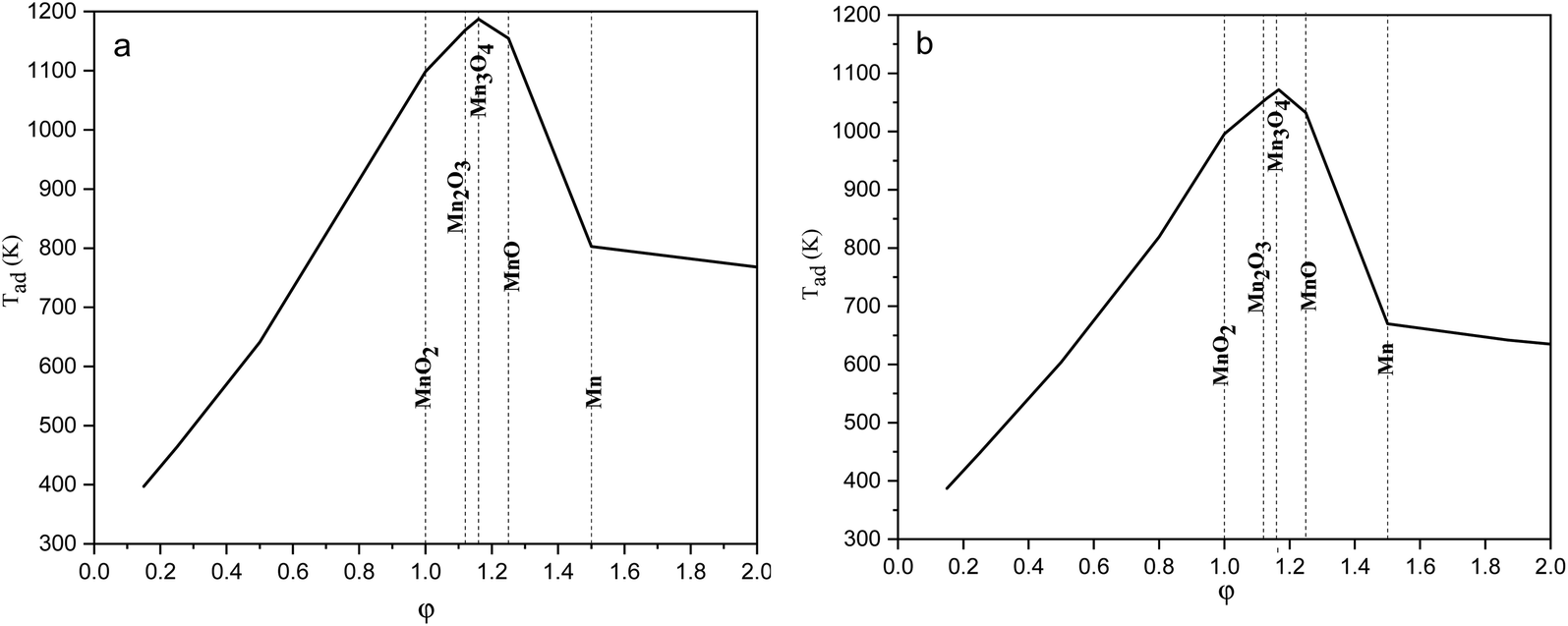 | ||
| Fig. 1 Adiabatic temperatures of the reactions versus the ϕ value considering (a) glycine, and (b) urea as fuel. | ||
The equilibrium oxygen pressure ranges for the stability of MnO2, Mn2O3, Mn3O4, MnO, and Mn are shown versus the temperature in Fig. 2, which were calculated by HSC Chemistry software. As indicated, at ambient atmosphere (PO2 = 0.21atm), MnO2 was stable until the temperature reached 755 K; while the stability temperature ranges of Mn2O3 and Mn3O4 were 755–1172 K and 1172–1853 K, respectively. Accordingly, the enhanced temperatures obtained during the synthesis were not favorable for the production of MnO2. Thus, φ values less than 1, which lead to lower adiabatic temperatures, are more desirable for the synthesis of MnO2.
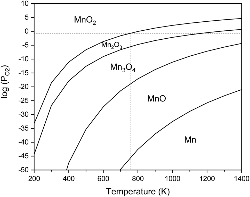 | ||
| Fig. 2 Stability regions of MnO2, Mn2O3, Mn3O4, MnO, and Mn in terms of the temperature and oxygen pressure. | ||
3.2 X-Ray diffraction results
Fig. 3 presents the XRD patterns of the synthesized powders according to the reactions mentioned for system 1 in Table 1 (samples G-1 and U-1). The purpose of this system was to assess the impact of the fuel type (glycine and urea) on the physicochemical properties of the synthesized manganese oxides. As indicated in Fig. 3, sample G-1 dominantly consisted of Mn3O4 (ICDD 24-0734) with traces of MnO (ICDD 075-0626); whereas, sample U-1 mostly showed Mn3O4 with insignificant amounts of Mn2O3 (ICDD 041-1442). In contrast with the theoretical expectations for system 1 (Table 1), MnO2 was not formed in these samples. This may be due to the decomposition of manganese nitrate, which is probable from the low temperatures. Therefore, a part of the manganese nitrate may have been decomposed during heating and combustion, which would have disturbed the initial stoichiometric ratio of the fuel and nitrate. Thus, there was an excess amount of fuel, which caused a more reductive condition and consequently led to the formation of Mn2O3, Mn3O4, and MnO instead of MnO2. Moreover, since the combustion temperature was higher than the stability temperature of MnO2 (which was less than 755 K, according to Fig. 2), the likely formed MnO2 particles could deform to give the oxides with lower valences.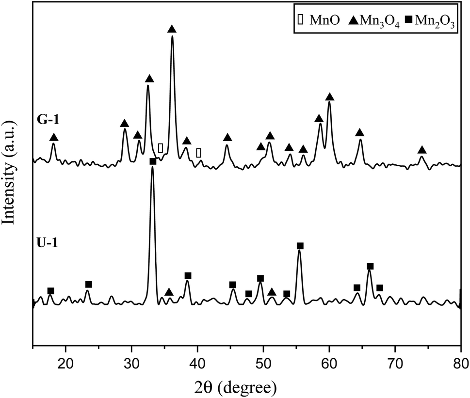 | ||
| Fig. 3 XRD patterns of the synthesized powders in the stoichiometric system using glycine and urea with φ = 1. | ||
Comparison of the results obtained by glycine and urea showed that glycine caused a more reductive condition, yielding the formation of Mn3O4 and MnO, while in the synthesis by urea, Mn3O4 and Mn2O3 were formed. This can be attributed to the lower boiling point of urea (135 °C) rather than glycine (241 °C). Therefore, during the heating up till the ignition of the synthesis, greater amounts of urea can probably evaporate; thus, the synthesis condition by glycine seems to be more reductive in the empirical condition. Moreover, the higher adiabatic temperature of the synthesis by glycine provides the proper condition for stability of the oxides with lower valences, as discussed in Fig. 2. Besides, it is obvious that the synthesis by glycine produced a lesser amount of gases (Table 1, system 1), which reduces the heat loss and consequently decreases the combustion temperature drop. Therefore, it could be concluded that urea is a better fuel for the synthesis of MnO2 due to its lower combustion temperature.
Fig. 4 indicates the XRD patterns of the samples of system 2. In this system, non-stoichiometric reactions with various φ ratios (φ = 0.15, 0.25, 0.5, 1, and 2) using glycine were assessed to study the effect of the φ value on the types of produced manganese oxides (samples G-0.15, G-0.25, G-0.5, G-1, and G-2). As can be seen, sample G-2 consisted of Mn3O4 and MnO oxides.19 However, the thermodynamic calculations shown in Fig. 1 suggest that metallic Mn could be expected at φ = 2. This can be attributed to the fact that the stability temperature of Mn, which is indicated in Fig. 2, is higher than the adiabatic temperature of the system. Although, if some Mn is formed, it would be oxidized by the oxygen in the atmosphere during the synthesis.
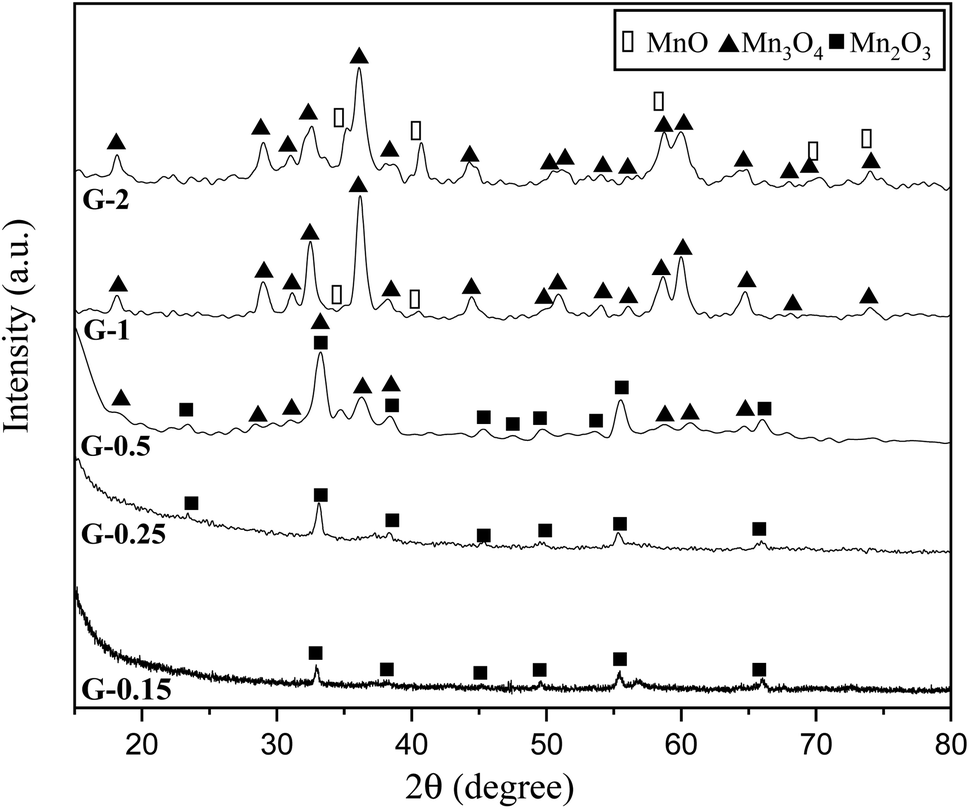 | ||
| Fig. 4 XRD patterns of the synthesized powders in the non-stoichiometric system with various φ ratios (φ = 0.15, 0.25, 0.5, 1, and 2) using glycine. | ||
According to Fig. 1, it could be anticipated that MnO2 would form in the samples with φ = 1 and less (i.e., samples G-0.15, G-0.25, G-0.5, and G-1). However, the XRD patterns showed Mn3O4 as the dominant oxide in sample G-1, and Mn2O3 as the dominant phase in samples G-0.15, G-0.25, and G-0.5. This could be attributed to the decomposition of manganese nitrate during heating and synthesis which increased the fuel to oxidizer ratio and provided a more reductive condition. As shown in Fig. 4, decreasing the φ value from 1 to 0.15 gradually led to the formation of Mn2O3 due to less reductive condition and the lower adiabatic temperature of the system. Despite the low φ value and adiabatic temperature, which provide proper conditions for the formation of MnO2, no evidence of MnO2 was observed in the XRD patterns, even for sample G-0.15. Accordingly, further attempts were followed using urea as a fuel (systems 3, 4, and 5), as described in Table 1.
The XRD patterns of the products attained by system 3 are shown in Fig. 5. In this system non-stoichiometric reactions with various φ ratios (φ = 0.15, 0.25, 0.4, 0.5, 0.6, 0.8, 1, and 2) using urea were investigated (samples U-0.15, U-0.25, U-0.4, U-0.5, U-0.6, U-0.8, U-1, and U-2). As indicated, sample U-2 did not show Mn formation because the temperature during the synthesis did not reach the stability temperature of Mn. This sample was mostly formed of Mn3O4 and MnO oxides.19
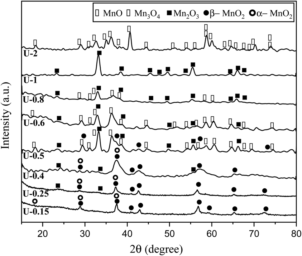 | ||
| Fig. 5 XRD patterns of the synthesized powders in the non-stoichiometric system with various φ ratios (φ = 0.15, 0.25,0.4, 0.5, 0.6, 0.8, 1, and 2) using urea. | ||
The XRD pattern of sample U-1 showed Mn2O3 as the dominant oxide. However, MnO2 was expected to form at φ = 1 and less. It returned to the decomposition of manganese nitrate during heating, which increases the real fuel to oxidizer ratio, resulting in a more reductive condition. Besides, the high combustion temperature of this sample was not appropriate for the formation of MnO2 which is stable at low temperatures.
Although it was anticipated that manganese oxides with higher valences, such as MnO2 and Mn2O3, would form with decreasing the φ ratio to values less than 1, an abnormal behavior was observed in the samples U-0.5, U-0.6, and U-0.8, which revealed Mn3O4. This could be attributed to the dissimilar conditions of urea evaporation during the heating and gel formation, which led to the unexpected behavior. This behavior was not observed in the samples synthesized by glycine because of the higher boiling point of glycine.
In order to assess the impact of the φ value on the temperature and duration of the pre-combustion step, the temperature was measured and plotted versus time during the synthesis of the third system. Fig. 6 displays the thermal profiles of the samples U-0.15, U-0.5, and U-1, which were obtained using a K-type thermocouple inserted in the synthesis environment and a data acquisition system for recording the temperature with time. A schematic of the main steps is illustrated in Table 2, including boiling, pre-combustion step (gel formation), combustion, and cooling. In the first step, the solution is heated to reach boiling point. During the boiling step, the temperature remains constant. Concentration of the solution gradually increases, leading to gel formation (pre-combustion step), which is accompanied by an enhancement of the temperature. Since the evaporation of fuel occurs rapidly in the pre-combustion step, the duration of this step has a considerable effect on the real φ value and reductive condition of the system. Elongation of this step yields more fuel loss and a less reductive condition. At the end of this step, ignition occurs, which is followed by smoldering. Finally, the products form and cool down to room temperature.
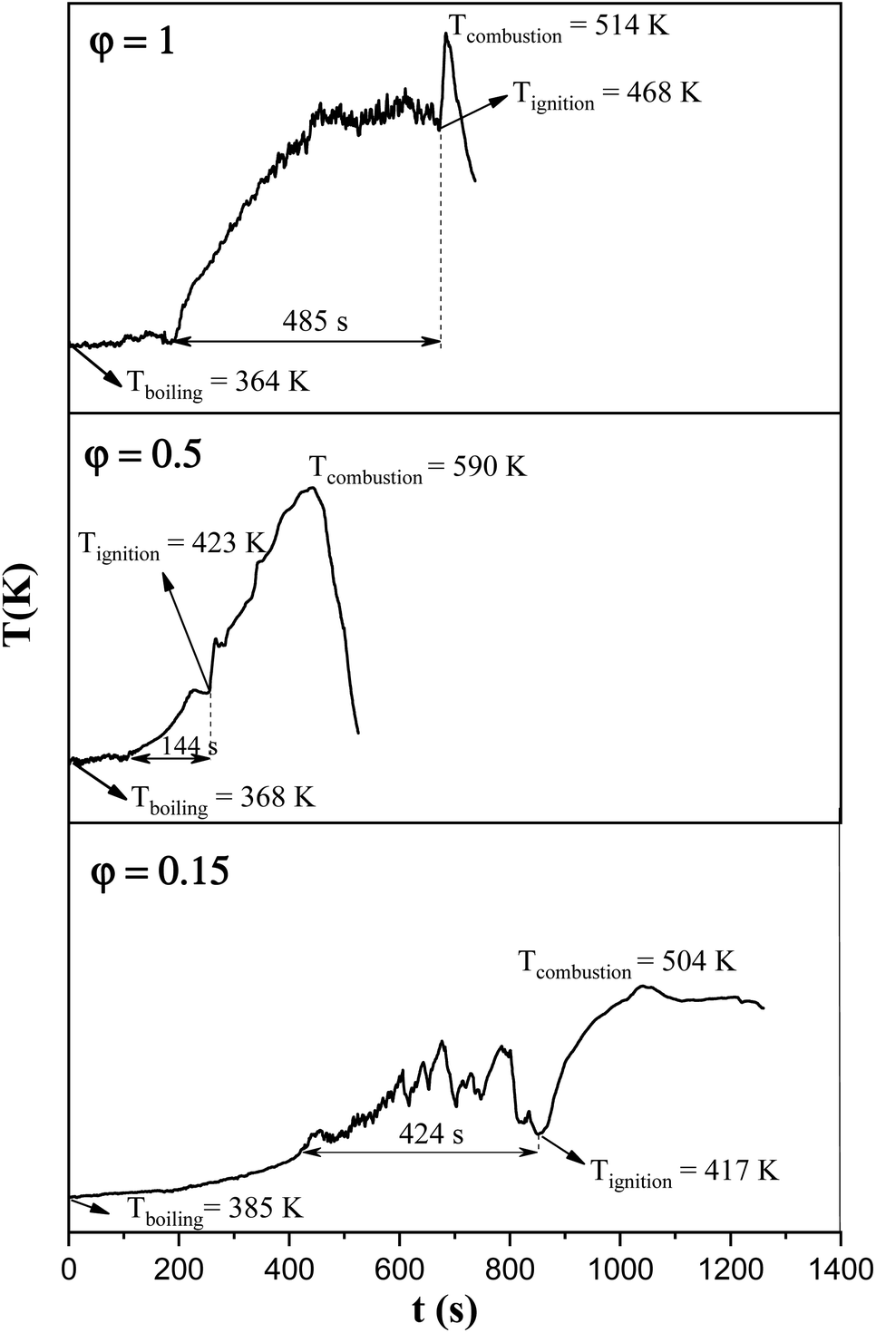 | ||
| Fig. 6 Temperature–time profile during the synthesis of the samples U-0.15, U-0.5, and U-1. | ||
| Boiling step | Pre-combustion step (gel formation) | Combustion | Cooling |
|---|---|---|---|
|
|
|
|
|
|
|
|
As depicted in Fig. 6, at φ = 0.5 (sample U-0.5), the pre-combustion time and the ignition temperature, which represents the final temperature of the pre-combustion step, were both lower than for the sample with φ = 1 (sample U-1). Thus, less urea evaporation occurred in sample U-0.5, resulting in a more reductive environment. Therefore, as shown in Fig. 5, Mn3O4 would be more likely to form at φ = 0.5 compared to at φ = 1. Accordingly, the unexpected formation of Mn3O4 by reducing the φ value from 1 to 0.8, 0.6, and 0.5 can be explained by the different pre-combustion duration and temperature.
Further decreasing the φ value (e.g., φ = 0.15) led to a prolonged pre-combustion time, as demonstrated in Fig. 6, which caused a higher loss of urea and thus a more oxidizing environment, which yielded manganese oxides with higher valences. Returning to Fig. 5, it could be found that reducing the φ value from 0.5 to 0.4, 0.25, and 0.15, which declined the reductive condition and the adiabatic temperature of the system, gradually led to the formation of oxides with higher valances, such as Mn2O3 and MnO2. Accordingly, in samples U-0.15 and U-0.25, the predominant amount of MnO2 was formed in two types: β-MnO2 (ICDD 24-0735) and α-MnO2 (ICDD 44-0141) polymorphs. However, the formation of α-MnO2 in these samples was insignificant and most of the MnO2 was revealed to be in the β structure.
It was previously found that cations such as K+ can stabilize the structure of α-MnO2.5,20 Consequently, KCl was added to the reaction mixture as a source of K+ in various K/Mn ratios of 0.006, 0.030, 0.059, and 0.259. Referring to Table 1, system 4, four samples, namely U–KCl-0.006, U–KCl-0.030, U–KCl-0.059, and U–KCl-0.259, were synthesized, and their XRD patterns are indicated in Fig. 7. As shown, the crystallinity of the samples was low and wide peaks appeared. Thus, the phase detection was carried out based only on the major peaks. As can be seen, a mixture of α and β-MnO2 was formed in the presence of K+; however, extra amounts of KCl decreased the intensity of MnO2 peaks and led to the formation of MnO10Cl8 (ICDD 30-0821). It could be noted that adding KCl did not have any significant effect on the adiabatic temperature.
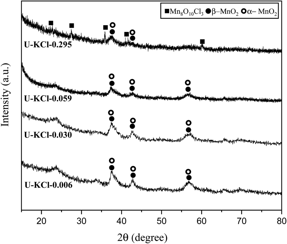 | ||
| Fig. 7 XRD patterns of the synthesized powders in the system using urea (φ = 0.25) with the addition of KCl in various K/Mn ratios of 0.006, 0.030, 0.059, and 0.259. | ||
Fig. 8(a) presents the XRD patterns related to the specimens synthesized with KNO3 as the stabilizer of α-MnO2 in various φ ratios (φ = 0.8, 0.85, 0.9, and 1). This system was investigated to study the effect of KNO3 on the formation of α-MnO2 in the final product (samples U–K-0.8, U–K-0.85, U–K-0.9, and U–K-1). As indicated, sample U–K-1 mostly consisted of α-MnO2 with some amounts of Mn2O3. As can be seen, the intensity of the peaks related to the Mn2O3 phase gradually decreased with reducing the ϕ value; until in sample U–K-0.8, an almost single phase of α-MnO2 was formed. The broadened peaks of α-MnO2 were a sign of the fine particle size of the synthesized powder. The stability of α-MnO2 could be attributed to the presence of K+ and the less reductive condition provided by the low φ values. The calculated adiabatic temperature of the reactions related to samples U–K-0.8, U–K-0.85, U–K-0.9, and U–K-1 were 923, 945, 966, and 1008 K, respectively. These values were higher than the relevant adiabatic temperatures calculated for the specimens without KNO3 (Fig. 1(b)), which was not proper for α-MnO2 formation. However, the influence of K+ overcame this and resulted in the stability of α-MnO2.
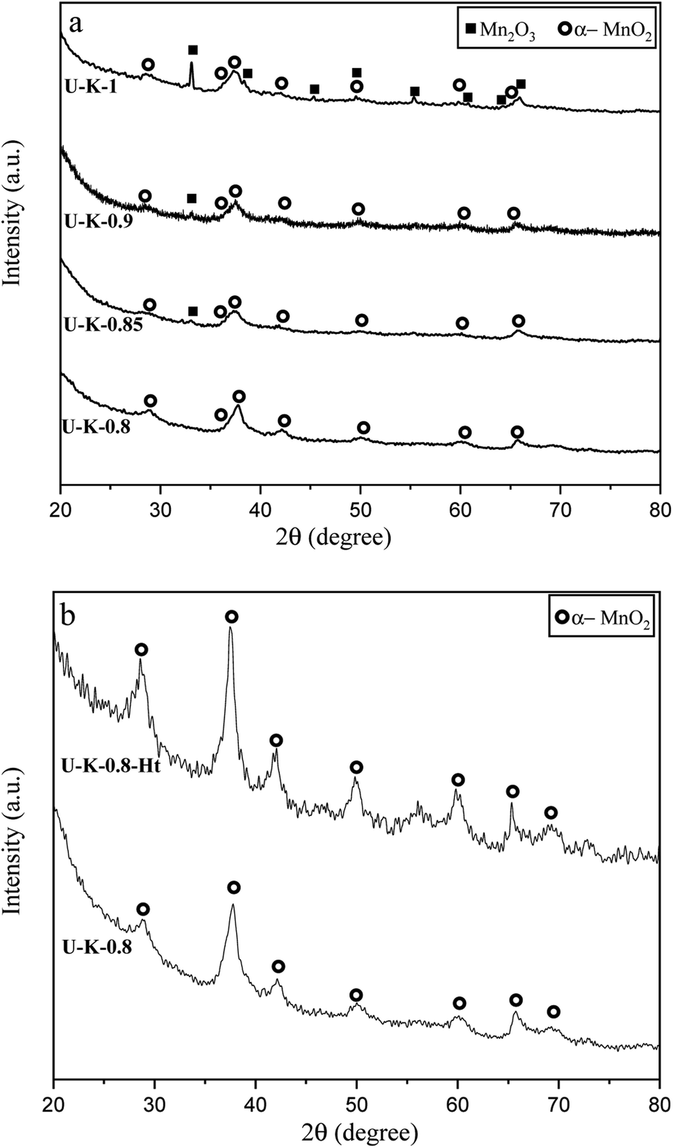 | ||
| Fig. 8 XRD patterns of the synthesized powders in (a) the system using urea with the addition of KNO3 in various φ ratios (φ = 0.8, 0.85, 0.9, and 1), (b) the sample synthesized at φ = 0.8 and annealed at 380 °C for 48 h. | ||
The as-synthesized sample U–K-0.8 was then annealed at 380 °C for 48 h to improve the crystallinity of the nanoparticles (sample U–K-0.8-Ht). As shown in Fig. 8(b), the intensity of the peaks increased due to the heat treatment, which implied a higher crystallinity of the sample.
3.3 Results of the particle-size analysis
In order to investigate the particle size of synthesized powders, PSA was carried out and the averaged results are shown in Fig. 9. As indicated, the samples synthesized by urea had smaller particle sizes than glycine. An explanation for this phenomenon may be related to the greater volume of combustion gas produced during the synthesis with urea. According to Table 1 (system 1), 9.444 mol of combustion gases was released during the synthesis with glycine; however, this amount for the synthesis with urea was 10.333 mol. Thus, a greater dispersion of powder particles occurred when urea was used, which resulted in a reduction of the possibility of the particles adhering and agglomeration.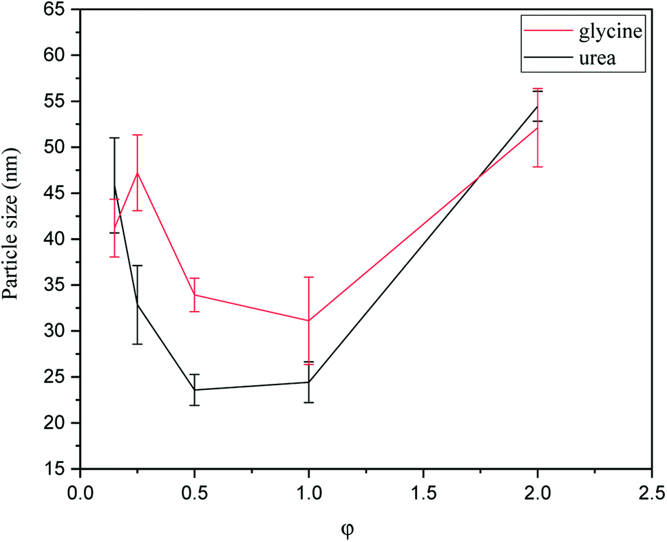 | ||
| Fig. 9 PSA results of the powders synthesized by glycine and urea in various φ ratios. | ||
As can be seen in Fig. 9, the particle size also varied by changing the φ value. Among the samples synthesized by glycine, the sample with φ = 1 (G-1) showed the minimum particle size. As discussed in Fig. 4, sample G-1 was mostly composed of Mn3O4, which was accompanied with the highest combustion temperature. When the combustion temperature was high, the rate of combustion increased, causing the products to form more quickly and not to stay at the enhanced temperatures for a long time. Therefore, the sintering and agglomeration of the particles were decreased in sample G-1 and consequently a finer particle size was achieved. Comparison of the samples synthesized by urea in various φ values showed that the minimum particle size was attained at φ = 0.5–1. Referring to Fig. 5, these samples mostly consisted of Mn3O4 and Mn2O3. Accordingly, the highest combustion temperature and rate occurred in the samples yielding the smallest particle size.
3.4 Field-emission scanning electron microscopy (FESEM)
As proof of evidence, FESEM imaging was carried out to reveal the morphology of the as-synthesized manganese oxides obtained by glycine and urea at various φ ratios. Fig. 10 indicates the morphology of the samples G-0.25 and G-1 in different magnifications. As shown in Fig. 10(a), sample G-0.25 revealed a granular morphology, indicating agglomerates of Mn2O3 nanoparticles with a ridged surface. However, sample G-1 (Fig. 10(b)) displayed a lacy morphology. Increasing the φ value led to the formation of Mn3O4 and MnO nanoparticles and consequently a higher combustion temperature, resulting in more agglomeration and sintering of the nanoparticles. On the other hand, the amounts of released gases were higher in sample G-1, which obviously caused greater porosity and more cavities.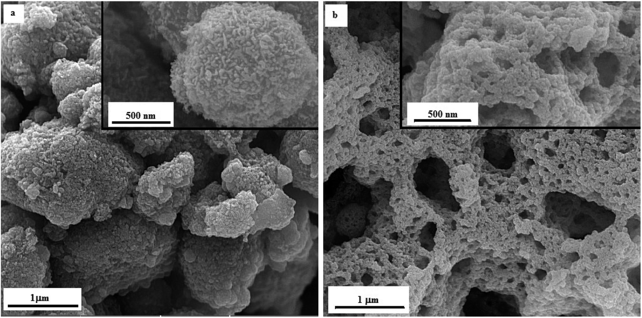 | ||
| Fig. 10 FESEM micrographs of the as-synthesized samples (a) G-0.25, and (b) G-1. | ||
The FESEM image of sample U-0.15 is presented in Fig. 11(a), which shows the MnO2 nanoparticles had a cauliflower-like morphology. However, sample U-1 (Fig. 11(b)) exhibited a granular morphology for Mn2O3 nanoparticles, as also revealed for sample G-0.25. Increasing the φ value to 2 (i.e., sample U-2) led to a lacy network morphology, as demonstrated in Fig. 11(c). Similar to sample G-1, this morphology can be attributed to the sintering of Mn3O4 and MnO nanoparticles, which was accompanied by the formation of cavities due to the huge volume of released gases.
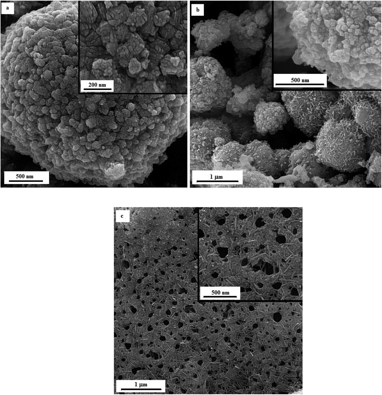 | ||
| Fig. 11 FESEM micrographs of the as-synthesized samples: (a) U-0.15, (b) U-1, and (c) U-2. | ||
Fig. 12 illustrates the FESEM micrographs of the samples synthesized by adding KNO3. A dandelion-like morphology with a needle/flake-like surface was revealed for the α-MnO2 nanoparticles in these samples. Increasing the φ value from 0.8 (sample U–K-0.8) to 0.9 (sample U–K-0.9) led to a finer morphology. Heat treating the product at 380 °C for 48 h resulted in fracture of the surface needles and ridges due to recrystallization and/or thermal stresses.
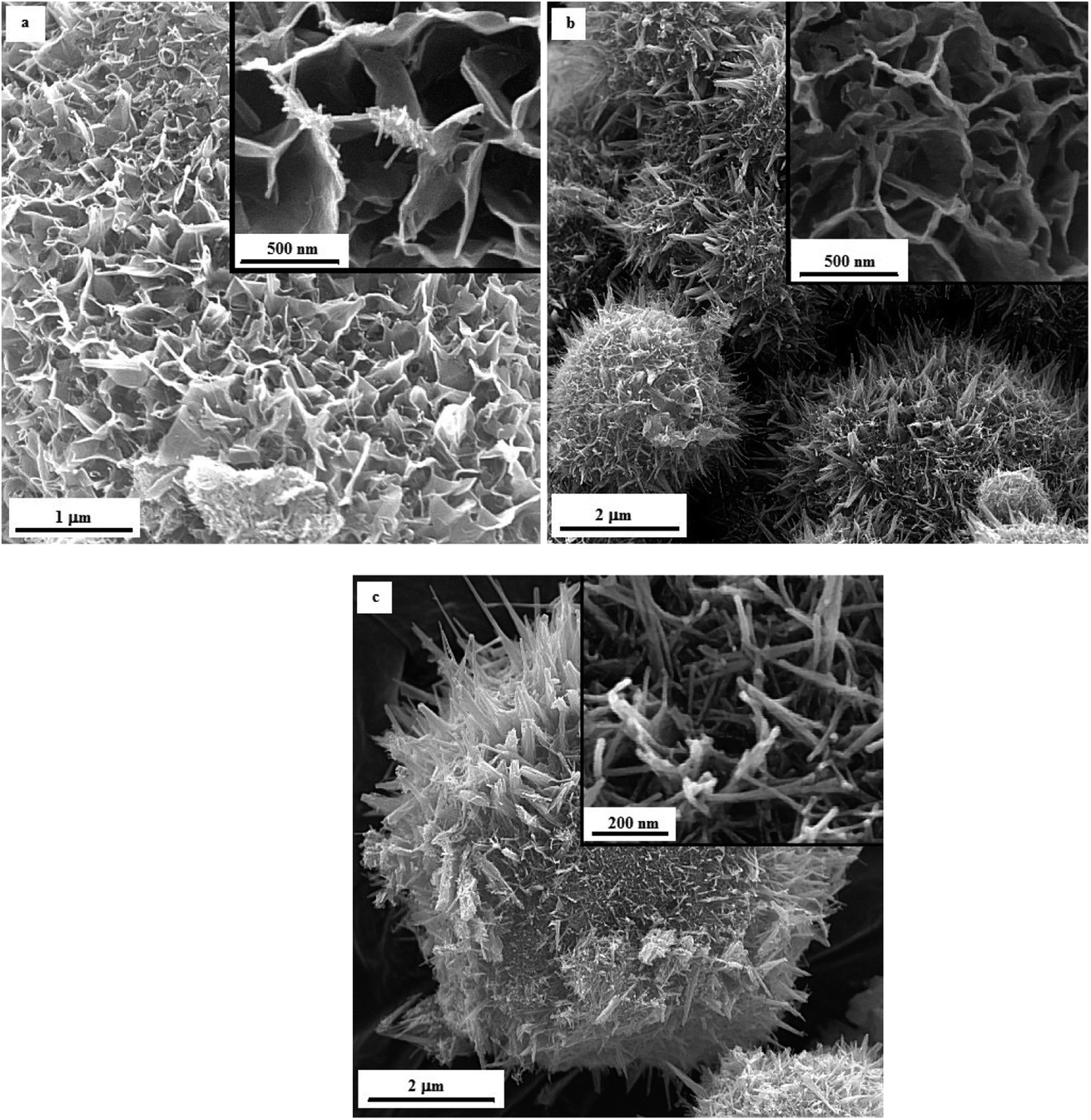 | ||
| Fig. 12 FESEM images of the as-synthesized samples: (a) U–K-0.8, (b) U–K-0.9, and (c) the heat-treated sample U–K-0.8-Ht. | ||
4 Conclusion
A new approach for the production of α-MnO2 nanoparticles was achieved using a modified solution combustion synthesis (SCS), in which α-MnO2 was synthesized in a one-step procedure with the addition of a stabilizer. To examine the effects of the fuel type, stabilizer, and fuel ratio on the morphology and phase composition of the final product, combustion synthesis was conducted using glycine and urea as the fuel and KCl and KNO3 as the stabilizer. The production of single-phase α-MnO2 was attained using urea under lean-fuel conditions (i.e., φ = 0.8) and in the presence of KNO3 as the stabilizer. The synthesized α-MnO2 exhibited a specific nanostructured dandelion-like morphology. Heat treating the synthesized α-MnO2 at 380 °C led to greater crystallinity.Conflicts of interest
There are no conflicts to declare.References
- F. W. Boyom-Tatchemo, F. Devred, G. Ndiffo-Yemeli, S. Laminsi and E. M. Gaigneaux, Plasma-induced redox reactions synthesis of nanosized α-, γ- and δ-MnO2 catalysts for dye degradation, Appl. Catal., B, 2020, 260, 118159, DOI:10.1016/j.apcatb.2019.118159.
- B. Yin, S. Zhang, H. Jiang, F. Qu and X. Wu, Phase-controlled synthesis of polymorphic MnO2 structures for electrochemical energy storage, J. Mater. Chem. A, 2015, 3, 5722–5729, 10.1039/C4TA06943A.
- N. Wang, W. Li, J. Liang, Y. Huang, Q. Cai, M. Hu, Y. Chen and Z. Shi, δ-MnO2 nanowires supported on carbon black with oxygen-containing functional groups for enhanced electrocatalytic oxygen reduction reaction, J. Alloys Compd., 2020, 846, 156396, DOI:10.1016/j.jallcom.2020.156396.
- A. A. Voskanyan, C. K. Ho and K. Y. Chan, 3D δ-MnO2 nanostructure with ultralarge mesopores as high-performance lithium-ion battery anode fabricated via colloidal solution combustion synthesis, J. Power Sources, 2019, 421, 162–168, DOI:10.1016/j.jpowsour.2019.03.022.
- L. M. Housel, L. Wang, A. Abraham, J. Huang, G. D. Renderos, C. D. Quilty, A. B. Brady, A. C. Marschilok, K. J. Takeuchi and E. S. Takeuchi, Investigation of α-MnO2 tunneled structures as model cation hosts for energy storage, Acc. Chem. Res., 2018, 51, 575–582, DOI:10.1021/acs.accounts.7b00478.
- A. F. Wells, Structural inorganic chemistry, Oxford University Press, United Kingdom, 5th edn, 1984 Search PubMed.
- Y. Yuan, A. Nie, G. M. Odegard, R. Xu, D. Zhou, S. Santhanagopalan, K. He, H. Asayesh-Ardakani, D. D. Meng, R. F. Klie, C. Johnson, J. Lu and R. Shahbazian-Yassar, Asynchronous crystal cell expansion during lithiation of K+-stabilized α-MnO2, Nano Lett., 2015, 15, 2998–3007, DOI:10.1021/nl5048913.
- L. Li and D. L. King, Synthesis and characterization of silver hollandite and its application in emission control, Chem. Mater., 2005, 17, 4335–4343, DOI:10.1021/cm0506508.
- A. S. Poyraz, J. Huang, C. J. Pelliccione, X. Tong, S. Cheng, L. Wu, Y. Zhu, A. C. Marschilok, K. J. Takeuchi and E. S. Takeuchi, Synthesis of cryptomelane type α-MnO2 (KxMn8O16) cathode materials with tunable K+ content: the role of tunnel cation concentration on electrochemistry, J. Mater. Chem. A, 2017, 5, 16914–16928, 10.1039/C7TA03476H.
- T. Gao and P. Norby, Frame stability of tunnel-structured cryptomelane nanofibers: the role of tunnel cations, Eur. J. Inorg. Chem., 2013,(28), 4948–4957, DOI:10.1002/ejic.201300602.
- N. Duan, S. L. Suib and C. L. O’Young, Sol–gel synthesis of cryptomelane, an octahedral molecular sieve, J. Chem. Soc., Chem. Commun., 1995,(13), 1367–1368, 10.1039/C39950001367.
- S. Ching, J. L. Roark, N. Duan and S. L. Suib, Sol−Gel route to the tunneled manganese oxide cryptomelane, Chem. Mater., 1997, 9, 750–754, DOI:10.1021/cm960460k.
- B. Lan, X. Zheng, G. Cheng, J. Han, W. Li, M. Sun and L. Yu, The art of balance: Engineering of structure defects and electrical conductivity of α-MnO2 for oxygen reduction reaction, Electrochim. Acta, 2018, 283, 459–466, DOI:10.1016/j.electacta.2018.06.195.
- N. Jabeen, Q. Xia, S. v. Savilov, S. M. Aldoshin, Y. Yu and H. Xia, Enhanced pseudocapacitive performance of α-MnO2 by cation preinsertion, ACS Appl. Mater. Interfaces, 2016, 8, 33732–33740, DOI:10.1021/acsami.6b12518.
- A. S. Mukasyan and P. Dinka, Novel approaches to solution-combustion synthesis of nanomaterials, Int. J. Self-Propag. High-Temp. Synth., 2007, 16, 23–35 CrossRef CAS.
- S. T. Aruna and A. S. Mukasyan, Combustion synthesis and nanomaterials, Curr. Opin. Solid State Mater. Sci., 2008, 12, 44–50, DOI:10.1016/j.cossms.2008.12.002.
- A. Varma, A. S. Mukasyan, A. S. Rogachev and K. V. Manukyan, Solution combustion synthesis of nanoscale materials, Chem. Rev., 2016, 116, 14493–14586, DOI:10.1021/acs.chemrev.6b00279.
- J. S. Sherin, J. K. Thomas and J. Suthagar, Combustion synthesis and magnetic studies of hausmannite, Mn3O4, nanoparticles, Int. J. Eng. Res. Develop., 2014, 10, 34–41 Search PubMed.
- H. Guo, Z. Zhang, Z. Jiang, M. Chen, H. Einaga and W. Shangguan, Catalytic activity of porous manganese oxides for benzene oxidation improved via citric acid solution combustion synthesis, J. Environ. Sci., 2020, 98, 196–204, DOI:10.1016/j.jes.2020.06.008.
- C. Zhou, J. Wang, X. Liu, F. Chen, Y. Di, S. Gao and Q. Shi, Magnetic and thermodynamic properties of α, β, γ and δ-MnO2, New J. Chem., 2018, 42, 8400–8407, 10.1039/C8NJ00896E.
| This journal is © The Royal Society of Chemistry 2022 |