
 Open Access Article
 This Open Access Article is licensed under a Creative Commons Attribution-Non Commercial 3.0 Unported Licence
A multiferroic iron arsenide monolayer†
Xiaoyu
Xuan
a,
Tingfan
Yang
a,
Jian
Zhou
 b,
Zhuhua
Zhang
*a and
Wanlin
Guo
a
b,
Zhuhua
Zhang
*a and
Wanlin
Guo
a
aKey Laboratory for Intelligent Nano Materials and Devices of Ministry of Education, State Key Laboratory of Mechanics and Control of Mechanical Structures, Institute for Frontier Science, Nanjing University of Aeronautics and Astronautics, Nanjing 210016, China. E-mail: chuwazhang@nuaa.edu.cn
bCenter for Alloy Innovation and Design, State Key Laboratory for Mechanical Behavior of Materials, Xi'an Jiaotong University, Xi'an 710049, China
First published on 31st January 2022
Abstract
Iron arsenide (FeAs) monolayers are known as a key component for building iron-based superconductors. Here, we predict by first-principles calculations that the FeAs monolayer is a highly stable and multiferroic material with coexisting ferroelasticity and antiferromagnetism. The ferroelasticity entails a reversible elastic strain of as large as 18% and an activation barrier of 20 meV per atom, attributed to a weak hybridization between Fe d and As p orbitals. The local moments of Fe atoms are oriented out-of-plane, so that the magnetic ordering is weakly coupled to the structural polarization. Interestingly, fluorination of the FeAs monolayer can align the local moments in parallel and reorient the easy axis along the in-plane direction. As such, the fluorinated FeAs monolayer is potentially a long-sought multiferroic material that enables a strong coupling between ferroelasticity and ferromagnetism.
Ferromagnetism, ferroelectricity and ferroelasticity are three typical ferroic properties. Materials that exhibit two or more ferroic order parameters simultaneously are multiferroics, which have been actively studied for decades due to their fundamental interest in physics and a variety of potential applications, such as non-volatile random access memory (RAM)1–3 and spintronics.4 Towards practical applications, it is of utmost importance to realize strong coupling between different ferroic orders in multiferroic materials, such that manipulation of one order parameter can effectively control the other(s). However, these ferroic orders inherently exclude one another, making multiferroic materials extremely rare in nature.1,3–5 Recent progress in theoretical design and experimental synthesis of two-dimensional (2D) functional materials has opened a new era of research in multiferroics, since lattices, atoms and even orbitals therein have exhibited flexibility in displacement and re-hybridization to form different ferroic orders. In particular, the discovery of intrinsic ferromagnetism in 2D van der Waals crystals has further fueled the development in this field.6 Despite tremendous research interest, reported 2D multiferroics by theories1,3–5,7,8 and experiments in the literature are mostly on magnetoelectricity where magnetic and electric orders coexist and interact via either spin-lattice or spin-orbit couplings.
In contrast, 2D multiferroics with concurrent ferroelasticity and magnetic ordering will enable strain manipulation of magnetism that can be complementary to the electric manner in magnetoelectric materials for achieving enriched functionalities.9 While ferroelasticity has been predicted in several 2D materials, most of their activation barriers for ferroelastic switching are either too high (>100 meV per atom) or too low (<5 meV per atom) to operate under ambient conditions. The over-low activation barriers are largely attributed to the low structural anisotropy of 2D materials, but a subtlety exists since strong structural anisotropy tends to prohibit ferroelasticity. Moreover, most calculated pathways for the ferroelastic switching displayed an abrupt change of energy, suggesting high transient stress that may break the materials. Recently, theories predicted a couple of 2D materials with ferroelasticity and magnetic order, but no appreciable coupling between them has been revealed.10 The challenge in achieving an effective coupling between ferroelasticity and magnetic order stems from the fact that the former arise from the lattice while the latter is from electronic orbitals.
In this work, we demonstrate that the FeAs monolayer is a prototype of this sort which exhibits a desirable activation barrier of 20 meV per atom, along with a smooth energy pathway for the ferroelastic switching using first-principles calculations. This excellent ferroelasticity originates from a weak hybridization between the Fe dxz,yz and As px,y orbitals. Although the FeAs monolayer is an antiferromagnetic metal with magnetic moments highly concentrated on the Fe atoms, fluorination can align the local moments to form a ferromagnetic order and simultaneously reorient the easy-axis along the in-plane direction, which then enables the ferroelasticity to strongly couple with the ferromagnetism.
First-principles calculations were performed within the framework of density functional theory (DFT) and with the exchange–correlation functional described by the generalized gradient approximation parameterized by Perdew, Burke, and Ernzerhof (GGA-PBE),11 as implemented in the VASP code.12,13 The core potential was described by the projector augmented-wave (PAW) method14 with a kinetic energy cutoff of 500 eV for the plane-wave basis on the valence electrons. The grid of k-point sampling for the Brillouin zone integration was set as 20 × 20 × 1 for calculations without spin–orbit coupling (SOC). A vacuum spacing of 15 Å was set to isolate neighboring periodic images. The HSE06 functional15 was employed to confirm the magnetic ground state at a k-grid of 12 × 12 × 1. The magnetocrystalline anisotropy energy was evaluated with the SOC at a denser k-grid of 48 × 48 × 1 by the DFT+U (U = 3 eV) method. The selection of U = 3 eV is based on a comparison of the band structure with that obtained by the HSE06 functional. The phonon dispersions were calculated using the Phonopy package16 with the finite displacement method. Ab initio molecular dynamics (AIMD) simulations were carried out with the canonical ensemble and a time step of 1 fs. The structures were fully relaxed until the force on each atom was less than 0.01 eV Å−1.
The unit cell of the FeAs monolayer possesses a Pmmn space group with lattice constants a = 3.17 Å (short axis) and b = 3.80 Å (long axis), where each Fe atom is surrounded by four As atoms that form a tetrahedron (Fig. 1a). The As atoms are equally separated into two layers that sandwich the Fe plane. The bond length of Fe–As is 2.34 Å along the x-direction but increases to 2.40 Å along the y-direction. The calculated phonon spectrum shows no imaginary frequencies, suggesting that the FeAs monolayer is dynamically stable (Fig. S1a†). To further evaluate the thermal stability of the FeAs monolayer, the AIMD simulations were carried out at 500 K for 10 ps using a 5 × 5 supercell. The snapshot plotted in Fig. S1b† shows no sign of any structural disruption or bond breaking at the end of simulation. Thus, the FeAs monolayer is stable above room temperature. For a mechanically stable 2D material, the elastic constants must fulfill the Born–Huang criteria: C66 > 0 and C11C22 − C122 > 0. To assess the mechanical stability of the FeAs monolayer, we have calculated its elastic constants. The results show C11 = 39.42 N m−1, C12 = 26.58 N m−1, C22 = 83.90 N m−1, and C66 = 39.45 N m−1, satisfying the Born–Huang criteria.
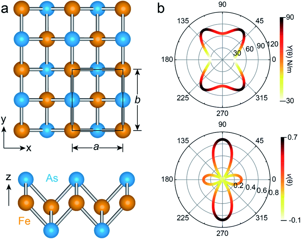 | ||
| Fig. 1 (a) Top and side views of the FeAs monolayer, where the unit cell is represented by the black rectangle. The orange and blue balls are Fe and As atoms, respectively. (b) Angular dependence of the Young's modulus Y(θ) and Poisson ratio ν(θ) of the FeAs monolayer, where the angle θ is defined relative to the x-direction. | ||
We next calculate the mechanical properties of the FeAs monolayer, i.e. the in-plane Young's modulus Y(θ) and Poisson ratio ν(θ). Based on the elastic constants, Young's modulus Y(θ) and Poisson ratio ν(θ) as functions of the angle θ relative to the x-axis direction can be expressed as follows:17

where A = (C11C22 − C122)/C66 − 2C12 and B = C11 + C12 − (C11C22 − C122)/C66. The angle-dependent functions are plotted in Fig. 1b. The calculated Young's moduli vary from 31.00 N m−1 to 88.02 N m−1, which are comparable to those of phosphorene (23–92 N m−1)18 but less than those of graphene (340 N m−1)19 and MoS2 (128 N m−1).20,21 The Poisson ratio ν(θ) of the FeAs monolayer reaches a maximum value of 0.67 along the y-axis direction. Such a distinctly large Poisson ratio suggests a sensitive structural response to the external stress applied along the x-axis direction. A Poisson ratio of 0.32 along the x-axis direction is similar to the case of MoS2.21 More interestingly, the FeAs monolayer exhibits negative Poisson ratios in the sector 39°< θ < 51° with a minimum value of −0.03.

We next examine the magnetic structure of the FeAs monolayer. Three typical magnetic states are considered: one ferromagnetic configuration, denoted as FM, and two antiferromagnetic configurations that are denoted as AFM1 and AFM2, respectively, as illustrated in Fig. 2. In AFM1, the nearest-neighbor spins are antiparallel to each other (stripe along x and y), while in AFM2, the spins are aligned antiparallel across the diagonal of the rectangular cell to form a diagonal striped spin pattern. The results obtained with the HSE06 functional show that the AFM1 configuration is more stable than both the FM and AFM2 configurations by 246.0 and 138.6 meV per Fe atom, respectively. These results are different from that in LaFeAsO, namely the parent material of the FeAs monolayer, where the AFM2 configuration has been declared as the ground state.22 The spin-density distribution of these three magnetic configurations plotted in Fig. S2† shows that the magnetic moments are mainly concentrated on the Fe atoms, with a magnetic moment of 3.0 μB around each Fe atom while the As atoms hold small opposite spin moments. The calculated electronic band structure (Fig. S3†) suggests that the FeAs monolayer is an AFM metal.
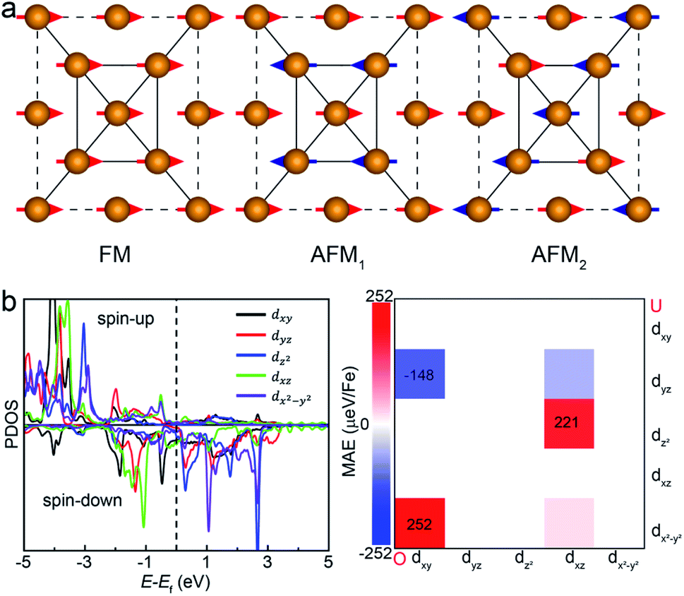 | ||
| Fig. 2 (a) The ferromagnetic configuration and two types of antiferromagnetic configurations of the FeAs monolayer. Only the Fe atoms are shown here for clarity. (b) The projected density of states (PDOS) of Fe-d orbitals and orbital resolved MAE of the FeAs monolayer. ‘O’ and ‘U’ represent occupied and unoccupied states, respectively. | ||
Another key magnetic property is the magnetocrystalline anisotropy, which determines the thermal stability of 2D magnetic ordering at finite temperatures according to the Mermin–Wagner theorem23 and mainly originates from the SOC interaction. The magnetocrystalline anisotropy can be characterized by calculating the magnetocrystalline anisotropy energy (MAE), which is defined as the total energy difference between out-of-plane and in-plane (x-axis and y-axis directions) spin configurations by considering the SOC interaction. The results show that the total energy of the AFM1 configuration with spins oriented along the out-of-plane direction is lower than those oriented along the x- and y-axes by 6 (MAEx–z) and 277 μeV (MAEy–z) per Fe atom, respectively. The magnetocrystalline anisotropy in the xz-plane can be considered to be isotropic for the corresponding small MAEx–z. The 2D material exhibiting an easy plane parallel to the z-axis stands in contrast to the previously reported 2D magnetic systems, such as CrI3 (ref. 6) and CrGeTe3 (ref. 24), which have either out-of-plane or in-plane easy-axis.
We then understand the mechanism of the xz easy plane by analyzing the interaction of d orbitals near the Fermi level. To understand the coupling between two d orbitals that contribute the most to MAEy–z, we adopt perturbation theory,25–27 expressed as
 , 〈dxy|Ly|dyz〉 = 1 and 〈dx2−y2|Ly|dxz〉 = 1. It is clear that the d orbital matrix elements and their energy difference determine the MAE. The orbital-resolved MAE (Ey − Ez) calculated based on the projected density of states is shown in Fig. 2b. It is found that the interaction between occupied dxy and unoccupied dx2−y2 orbitals and the interaction between occupied dxz and unoccupied dz2 orbitals give a positive contribution to the MAE, while the interaction between occupied dxy and unoccupied dyz orbitals contribute a negative value to the total MAE. The easy plane along the normal of the basal plane determines that the magnetic order in the FeAs monolayer will weakly respond to any in-plane structural transition, such as the ferroelastic transition discussed below.
The rectangular lattice of the FeAs monolayer motivates us to explore its ferroelasticity, which is assessed by computing the ferroelastic switching pathway and activation energy barrier. The initial and final states of the FeAs monolayer are degenerate and share the same structure but with the lattice rotated by 90° from each other as shown in the inset of Fig. 3. The configuration with a square lattice shown in the inset of Fig. 3 is the transition state (TS), where all the Fe atoms are coplanar with optimized lattice constant d = 3.52 Å. To estimate the activation barrier, the pathway of ferroelastic switching is computed using the uniaxial strain method and the climbing image nudged elastic band (NEB)28 method with the energy profile plotted as a function of strain (Fig. 3). The activation energy barrier of the FeAs monolayer is about 20 meV per atom, which is higher than those of SnO (0.37 meV per atom),10 SnS (1.3 meV per atom), SnSe (4.2 meV per atom), and GeSe (9.5 meV per atom),29 but lower than those of borophane (0.1 eV per atom),30 phosphorene (0.2 eV per atom),29 and InOY (Y = Cl and Br, 79–106 eV per atom),31 and can be comparable to those of GeS (22.6 meV per atom),29 ZrAsX (X = Cl and Br, 21.11–32.70 meV per atom),32 and t-YN (33 meV per atom).33 Different from the ferroelastic phosphorene and its analogues, the energy pathway of the FeAs monolayer exhibits a smooth profile without an abrupt change. Besides, there is no bond breaking or reforming during the ferroelastic switching as all the Fe–As bonding lengths are larger than 2.34 Å but less than 2.40 Å during the ferroelastic switching process, indicating that the ferroelastic switching of the FeAs monolayer is easier to manipulate in experiments than that of phosphorene and its analogues. While the reversible ferroelastic strain ε, defined as (b/a − 1), is 19.9% and lower than 37.9% for phosphorene, it is sufficient to convey a strong signal for structural switching.
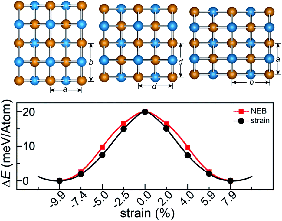 | ||
| Fig. 3 Calculated minimum energy pathways for ferroelastic switching of the FeAs monolayer. | ||
This outstanding ferroelastic performance of the FeAs monolayer is attributed to the tetragonal structure which is degenerate from a highly symmetric parental structure (the TS phase) without any bond breaking or reforming. We then test whether FeP and RuAs monolayers have similar ferroelasticity, as they can be designed from the FeAs monolayer by replacing only one element with its congener. The results plotted in Fig. S4† show that both the FeP and RuAs monolayers have only one minimum energy state at the strain-free state, proving that both the FeP and RuAs monolayers are non-ferroelastic. These results indicate that the ferroelasticity in the FeAs monolayer is quite unique. This is further supported by the calculations showing that the CoAs monolayer is not ferroelastic either. These results motivate us to gain an in-depth understanding of ferroelasticity in the FeAs monolayer.
As the Γ point in the Brillouin zone belongs to the same point group as the lattice, the electronic states at the Γ point affect the structural shape of a material. Thus, we check the hybridization between d and p orbitals by plotting the projected wave function character of the band structures. The band structures (see Fig. S5†) of the FeAs, FeP, RuAs and CoAs monolayers with d and p contributions in the TS structural models show that there are three major hybridizations between the d and p orbitals at the Γ point denoted as dz2–pz, dx2−y2–pz, and dxz,yz–px,y. Among the three d–p hybridizations, only the dxz,yz–px,y is doubly degenerate and directive. The hybridization of dxz,yz–px,y results in four states denoted as states 1, 2, 3 and 4 that are ranked from low to high by energy (Fig. S5†). We mainly focus on the states 1 and 2 because they are below the Fermi level. In the state 1, the p orbitals have contributions of 17.3%, 26.4%, 20.1% and 24.0%, while these values increase to 34.6%, 65.3%, 40.6% and 49.2% in the state 2, for FeAs, FeP, CoAs and RuAs monolayers, respectively. Compared with the FeP, CoAs and RuAs monolayers, the lower contribution of p orbitals to the state 1 in the FeAs monolayer indicates a weak hybridization of dxz,yz–px,y, which has been confirmed by real-space distributions of partial charge densities of state 1 plotted in Fig. 4 and state 2 plotted in Fig. S6.† This weak hybridization tends to lead to the distortion of the FeAs monolayer from a square lattice to a rectangular structure, so as to increase the hybridization along the y-axis direction while sacrificing that along the x-axis direction. Orbital analysis of the FeAs monolayer in its ground state confirms this scenario; in this case, the contribution of the py orbital to state 1 increases to 22.8% (Fig. S7a†) while that of the px orbital to state 1 decreases to 13.1% (Fig. S7b†). Note that the 2D FeSe and FeTe, which have similar atomic structures to the FeAs monolayer, have been experimentally synthesized on SiO2/Si substrates via chemical vapor deposition at ambient pressure,34,35 indicating that the FeAs monolayer can potentially be synthesized using the same methods.
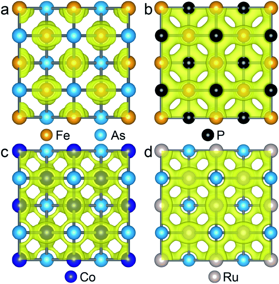 | ||
| Fig. 4 Isosurface plots of the partial charge density of state 1 in FeAs (a), FeP (b), CoAs (c) and RuAs (d) monolayers with an isosurface value of 0.054 e Å−3. | ||
Additionally, inspired by recently reported “Li decorated FeSe”,36 we attempt to use fluorine atoms to decorate the FeAs monolayer to modulate the magnetism. Note that fluorination of graphene37 and boron nitride38 has been performed experimentally. In addition, F atoms do not form clusters on the sample surface, rather than metal atoms that tend to cluster on substrates via strong orbital hybridizations.39 The results of phonon spectra (Fig. S9†) show that the FeAs monolayer with fluorine adsorbed on the As atoms is stable, while the FeAs monolayer with fluorine adsorbed on the opposite side of the As atoms (Fig. S8a†) is metastable. However, the former which leads to the ferroelasticity in the FeAs monolayer vanishes while the latter, denoted as FeAsF, maintains this ferroelastic property. The pathway of ferroelastic switching as plotted in Fig. 5a shows that the activation barrier of the FeAsF monolayer is 300 meV per atom, about 15 times higher than that of the FeAs monolayer. This high barrier is attributed to the Fe–F bond breaking and reforming during the ferroelastic switching. However, the magnetic ground state of the FeAs monolayer changes from the AFM1 state to the FM state upon the fluorination, where the FM state is more stable than the AFM1 and AFM2 states by 18.0 and 20.0 meV per Fe atom, respectively. This conversion of the magnetic ground state is attributed to the crystal field changing of Fe atoms, whose crystal field changes from a tetrahedron field to an octahedron field upon fluorination. This crystal field change brings a new exchange channel Fe–F–Fe which leads to ferromagnetic coupling as the bond angle of Fe–F–Fe is nearly 90°. The Curie temperature of the FeAsF monolayer is estimated to be 65 K using a simple Heisenberg-like model  by Monte Carlo simulation (Fig. S10†). By considering the SOC interaction, the total energy of the FeAsF monolayer along the out-of-plane direction is higher than those along the x- and y-axis directions by 434 and 275 μeV per Fe, respectively. This means that the easy axis is also reoriented along the in-plane direction.
 | ||
| Fig. 5 Calculated minimum energy pathways for ferroelastic switching of the FeAsF monolayer (a), along with the magnetocrystalline anisotropic energy during ferroelastic switching (b). The in-plane easy-axis directions of the monolayer are marked by arrows, while the out-of-plane easy-axis direction is marked by point circles. | ||
This in-plane easy axis of the FeAsF monolayer will enable a strong coupling with the ferroelastic switching. For example, the easy axis along the x-axis direction is reoriented to the y-axis direction after the ferroelastic switching, rendering the FeAsF monolayer a long-sought multiferroic material that allows for strain manipulation of ferromagnetism. The strain increases MAEx–z from −338 μeV per Fe at ε = −18.9% to −26 μeV per Fe at ε = −12.6% and MAEy–z increases from −75 μeV per Fe at ε = −18.9% to 322 μeV per Fe at ε = −12.6%, suggesting that the magnetization remains oriented along the x-axis direction in this strain range. With the further increase of ε to −6.3%, both the MAEx–z and MAEy–z become positive to switch the magnetization along the z-axis direction. At ε = 0%, the monolayer reaches the transition state with an out-of-plane easy axis. Beyond the transition state, the MAE follows the same variation trend as that from the initial to the transition state, except that the values of MAEx–z and MAEy–z are swapped. MAEy–z reaches −434 μeV per Fe in the final state, confirming a complete switching of the easy axis to the y-axis direction. These results delineate an explicit coupling between ferroelasticity and ferromagnetism.
In conclusion, our intensive first-principles calculations have suggested the FeAs monolayer as a new 2D multiferroic material. The ferroelasticity in the FeAs monolayer exhibits a desirable barrier of 20 meV per atom for operation under ambient conditions and a smooth energy pathway to diminish the impact of transient stress on the lattice structure. The ferroelasticity results from a weak hybridization between d and p orbitals. On the other hand, each Fe atom exhibits a magnetic moment of 3 μB and interacts in an antiferromagnetic way with a normal easy plane. The ferroelasticity and magnetism are hence loosely coupled to each other. Yet, fluorination of the FeAs monolayer with an activation barrier of 300 meV per atom aligns the spin moments in a ferromagnetic state and reorients the easy axis along the x-axis direction, which enables the external strain to control the orientation of polarized spins. Our results may inspire future effort for devising more multiferroic monolayers for potential applications in advanced information devices.
Conflicts of interest
There are no conflicts to declare.Acknowledgements
This work was supported by National Key Research and Development Program of China (2019YFA0705400), the National Natural Science Foundation of China (11772153, 22073048, and 21903063), the Research Fund of State Key Laboratory of Mechanics and Control of Mechanical Structures (MCMS-E-0420K01), the Natural Science Foundation of Jiangsu Province (BK20190018), and a Project by the Priority Academic Program Development of Jiangsu Higher Education Institutions.References
- Z. Tu, M. Wu and X. C. Zeng, J. Phys. Chem. Lett., 2017, 8, 1973–1978 CrossRef CAS PubMed.
- W. Ding, J. Zhu, Z. Wang, Y. Gao, D. Xiao, Y. Gu, Z. Zhang and W. Zhu, Nat. Commun., 2017, 8, 14956 CrossRef CAS PubMed.
- Z. Tu and M. Wu, Adv. Electron. Mater., 2019, 5, 1800960 CrossRef.
- C. Huang, Y. Du, H. Wu, H. Xiang, K. Deng and E. Kan, Phys. Rev. Lett., 2018, 120, 147601 CrossRef PubMed.
- T. Zhong, X. Li, M. Wu and J. M. Liu, Natl. Sci. Rev., 2020, 7, 373–380 CrossRef CAS PubMed.
- B. Huang, G. Clark, E. Navarro-Moratalla, D. R. Klein, R. Cheng, K. L. Seyler, D. Zhong, E. Schmidgall, M. A. McGuire, D. H. Cobden, W. Yao, D. Xiao, P. Jarillo-Herrero and X. Xu, Nature, 2017, 546, 270–273 CrossRef CAS PubMed.
- S. Zhang, R. Xu, N. Luo and X. Zou, Nanoscale, 2021, 13, 1398–1424 RSC.
- Y. Lu, R. Fei, X. Lu, L. Zhu, L. Wang and L. Yang, ACS Appl. Mater. Interfaces, 2020, 12, 6243–6249 CrossRef CAS PubMed.
- S. Zhang, R. Xu, W. Duan and X. Zou, Adv. Funct. Mater., 2019, 29, 1808380 CrossRef.
- L. Seixas, A. S. Rodin, A. Carvalho and A. H. Castro Neto, Phys. Rev. Lett., 2016, 116, 206803 CrossRef CAS PubMed.
- J. P. Perdew, K. Burke and M. Ernzerhof, Phys. Rev. Lett., 1996, 77, 3865 CrossRef CAS PubMed.
- G. Kresse and J. Hafner, Phys. Rev. B: Condens. Matter Mater. Phys., 1994, 49, 14251–14269 CrossRef CAS PubMed.
- G. Kresse and J. Furthmüller, Phys. Rev. B: Condens. Matter Mater. Phys., 1996, 54, 11169–11186 CrossRef CAS PubMed.
- P. E. Blöchl, Phys. Rev. B: Condens. Matter Mater. Phys., 1994, 50, 17953–17979 CrossRef PubMed.
- J. Paier, M. Marsman, K. Hummer, G. Kresse, I. C. Gerber and J. G. Angyan, J. Chem. Phys., 2006, 124, 154709 CrossRef CAS PubMed.
- A. Togo and I. Tanaka, Scr. Mater., 2015, 108, 1–5 CrossRef CAS.
- E. Cadelano, P. L. Palla, S. Giordano and L. Colombo, Phys. Rev. B: Condens. Matter Mater. Phys., 2010, 82, 235414 CrossRef.
- L. Wang, A. Kutana, X. Zou and B. I. Yakobson, Nanoscale, 2015, 7, 9746–9751 RSC.
- C. Lee, X. Wei, J. W. Kysar and J. Hone, Science, 2008, 321, 385–388 CrossRef CAS PubMed.
- Y. Cai, G. Zhang and Y. W. Zhang, J. Am. Chem. Soc., 2014, 136, 6269–6275 CrossRef CAS PubMed.
- Z. Zhang, Y. Yang, E. S. Penev and B. I. Yakobson, Adv. Funct. Mater., 2017, 27, 1605059 CrossRef.
- T. Yildirim, Phys. Rev. Lett., 2008, 101, 057010 CrossRef CAS PubMed.
- N. D. Mermin and H. Wagner, Phys. Rev. Lett., 1966, 17, 1133–1136 CrossRef CAS.
- C. Gong, L. Li, Z. Li, H. Ji, A. Stern, Y. Xia, T. Cao, W. Bao, C. Wang, Y. Wang, Z. Q. Qiu, R. J. Cava, S. G. Louie, J. Xia and X. Zhang, Nature, 2017, 546, 265–269 CrossRef CAS PubMed.
- D. Wang, R. Wu and A. J. Freeman, Phys. Rev. B: Condens. Matter Mater. Phys., 1993, 47, 14932–14947 CrossRef CAS PubMed.
- R. Li, J. Jiang, X. Shi, W. Mi and H. Bai, ACS Appl. Mater. Interfaces, 2021, 13, 38897–38905 CrossRef CAS PubMed.
- J. Hu and R. Wu, Nano Lett., 2014, 14, 1853–1858 CrossRef CAS PubMed.
- T. D. Kuhne, M. Iannuzzi, M. Del Ben, V. V. Rybkin, P. Seewald, F. Stein, T. Laino, R. Z. Khaliullin, O. Schutt, F. Schiffmann, D. Golze, J. Wilhelm, S. Chulkov, M. H. Bani-Hashemian, V. Weber, U. Borstnik, M. Taillefumier, A. S. Jakobovits, A. Lazzaro, H. Pabst, T. Muller, R. Schade, M. Guidon, S. Andermatt, N. Holmberg, G. K. Schenter, A. Hehn, A. Bussy, F. Belleflamme, G. Tabacchi, A. Gloss, M. Lass, I. Bethune, C. J. Mundy, C. Plessl, M. Watkins, J. VandeVondele, M. Krack and J. Hutter, J. Chem. Phys., 2020, 152, 194103 CrossRef PubMed.
- M. Wu and X. C. Zeng, Nano Lett., 2016, 16, 3236–3241 CrossRef CAS PubMed.
- L. Kou, Y. Ma, C. Tang, Z. Sun, A. Du and C. Chen, Nano Lett., 2016, 16, 7910–7914 CrossRef CAS PubMed.
- X. Xu, Y. Ma, B. Huang and Y. Dai, Phys. Chem. Chem. Phys., 2019, 21, 7440–7446 RSC.
- X. Hu, N. Mao, H. Wang, C. Niu, B. Huang and Y. Dai, J. Mater. Chem. C, 2019, 7, 9743–9747 RSC.
- B. Xu, H. Xiang, J. Yin, Y. Xia and Z. Liu, Nanoscale, 2017, 10, 215–221 RSC.
- L. Kang, C. Ye, X. Zhao, X. Zhou, J. Hu, Q. Li, D. Liu, C. M. Das, J. Yang, D. Hu, J. Chen, X. Cao, Y. Zhang, M. Xu, J. Di, D. Tian, P. Song, G. Kutty, Q. Zeng, Q. Fu, Y. Deng, J. Zhou, A. Ariando, F. Miao, G. Hong, Y. Huang, S. J. Pennycook, K. T. Yong, W. Ji, X. Renshaw Wang and Z. Liu, Nat. Commun., 2020, 11, 3729 CrossRef CAS PubMed.
- K. D. Oyler, X. Ke, I. T. Sines, P. Schiffer and R. E. Schaak, Chem. Mater., 2009, 21, 3655–3661 CrossRef CAS.
- Y. Li, J. Li, Y. Li, M. Ye, F. Zheng, Z. Zhang, J. Fu, W. Duan and Y. Xu, Phys. Rev. Lett., 2020, 125, 086401 CrossRef CAS PubMed.
- S. H. Cheng, K. Zou, F. Okino, H. R. Gutierrez, A. Gupta, N. Shen, P. C. Eklund, J. O. Sofo and J. Zhu, Phys. Rev. B: Condens. Matter Mater. Phys., 2010, 81, 205435 CrossRef.
- M. Du, X. Li, A. Wang, Y. Wu, X. Hao and M. Zhao, Angew. Chem., Int. Ed. Engl., 2014, 53, 3645–3649 CrossRef CAS PubMed.
- J. Zhou, Q. Sun, Q. Wang and P. Jena, Phys. Rev. B: Condens. Matter Mater. Phys., 2014, 90, 205427 CrossRef.
Footnote |
| † Electronic supplementary information (ESI) available. See DOI: 10.1039/d1na00805f |
| This journal is © The Royal Society of Chemistry 2022 |