 Open Access Article
Synergy between iron oxide sites and nitrogen-doped carbon xerogel/diamond matrix for boosting the oxygen reduction reaction†
Abdalla
Abdelwahab
 ab,
Ahmed A.
Farghali
a and
Abeer
Enaiet Allah
 *c
*c
aMaterials Science and Nanotechnology Department, Faculty of Postgraduate Studies for Advanced Sciences, Beni-Suef University, Beni-Suef 62511, Egypt
bFaculty of Science, Galala University, Sokhna, Suez 43511, Egypt
cChemistry Department, Faculty of Science, Beni-Suef University, Beni-Suef 62511, Egypt. E-mail: abeer.abdelaal@science.bsu.edu.eg
First published on 11th January 2022
Abstract
The innovative design and facile synthesis of efficient and stable electrocatalysts for the oxygen reduction reaction (ORR) are crucial in the field of fuel cells. Herein, the facile synthesis of an iron oxide@nitrogen-doped carbon diamond (FeOx@NCD) composite via an effective pyrolysis strategy is reported. The properties of this electrocatalyst, including a high density of active sites, nitrogen doping, accessible surface area, well dispersed pyramidal morphology of the iron oxide, and the porous structure of the carbon matrix, promote a highly active oxygen reduction reaction (ORR) performance. The electrocatalyst exhibits outstanding stability, with a half-wave potential of 0.692 V in alkaline solution (0.1 M KOH), as well as a limiting current density of −31.5 mA cm−2 at 0.17 V vs. RHE. This study highlights the benefits of hybridizing sp2 carbon xerogel and sp3 diamond carbon allotropes with iron oxide to boost the ORR activity. The proposed strategy opens up an avenue for designing advanced carbon-supported metal oxide catalysts that exhibit excellent electrocatalytic performance.
1. Introduction
Although fossil fuels are currently the main energy source worldwide, their use cannot satisfy global energy demands as reserves are being constantly depleted as the worldwide population increases.1–3 Moreover, fossil fuel emissions pollute air and water, which has brought about an environmental crisis.1 Thus, it is imperative to devote a substantial amount of research time toward the pursuit of alternative renewable and sustainable energy sources.4 Fuel cell technology is considered to be one of the most promising, efficient, and sustainable zero-emission technologies available for electrochemical energy conversion devices.5,6 However, some drawbacks have hampered the large-scale commercialization of fuel cells, including their susceptibility toward methanol and carbon monoxide (CO) deactivation, unsatisfactory long-term durability, and the high costs of platinum (Pt)-based electrocatalysts.7,8 However, the biggest limitation of fuel cells by far is the sluggish kinetics of the cathodic oxygen reduction reaction (ORR), which is the major limiting half-reaction that hinders the further progress of this technology.1,9Conventionally, Pt and its alloys have been proven to be the most efficient, and thus most widely used, electrocatalysts for the ORR, as a result of their high catalytic.6,10 However, as well as improving the ORR activity, studies have been focused on lowering the Pt content of electrocatalysts to reduce costs. This can be achieved using another substrate, such as metals, carbon, conducting polymers, oxides, or carbides.11–13 Unfortunately, when impregnated in a support Pt nanoparticles undergo leaching and agglomerate into larger nanoparticles due to the Ostwald ripening effect, thus resulting in instability and poor activity of the material during long-term operation.1,11 Consequently, developing efficient, durable, cheap, and stable catalysts with high tolerance toward CO and methanol to expedite the ORR process in fuel cell technology is of great importance. To date, Pt-free and earth-abundant electrocatalysts, such as those based on transition metal oxide (TMO), carbide, sulfide, and nitride compounds, have been investigated.14,15 However, despite the significant improvements that have been achieved to date, the long-term durability and stability of these catalysts remain a key challenge due to the particle aggregation and metal corrosion that occur in these materials at a high working potential.5,16 In contrast to TMO compounds, TMO–carbon composites are more stable and exhibit a high surface area for the dispersion of a metal oxide catalyst, with satisfactory results reported in the literature.5 Therefore, various carbon-based electrocatalyst supports, such as graphene,17 nanodiamond (ND),18 carbon nanotubes (CNTs),19 and carbon xerogels (CXs)20–22 have been demonstrated to show efficient electrocatalytic activity toward the ORR. Among these materials, there has been deep insight into nitrogen-doped carbon materials (NC), which exhibit remarkable electrocatalytic activity due to their high charge density and localized charge distribution induced by dopants along the electrode surface.23–26
As ORR performance has been shown to be affected by the number of active species, high conductivity, and surface area of materials, NC materials should be engineered with a high concentration of active sites.27,28 Essentially, there are two factors that influence the performance of electrocatalysts; the first being the chemical composition, which is related to the number of active sites, the other being the specific surface area and pore structure, which determine the accessibility of the interfacial transport features of the relevant ORR species.7,25,29,30 In this context, nitrogen-doped CXs (NCXs) are novel structures comprising sp2-bonded carbon atoms, an open porous structure, large specific surface area, and high electrical conductivity, which manifest in exhibiting outstanding electrochemical activity.24 The porous structure of NCXs presents a number of active sites for potential electrostatic attraction and the continuous transport of ions and electrons on the electrode surface. Nevertheless, sp2-bonded carbon materials are vulnerable to oxidation and corrosion under a fuel cell environment, as a result of high potential and the presence of moisture. This corrosion then results in the loss of durability and activity of these materials.9,31 Therefore, it is necessary to synthesize oxidation-resistant electrocatalyst supports containing NC materials.
ND is a new metastable sp3-hybridized carbon allotrope that exhibits excellent electrical and mechanical properties, a large surface area, and a tunable surface structure.32,33 Therefore, the integration of multiple carbon allotropes has played a crucial role in the development of new state-of-the-art electrocatalysts for the ORR. The fine combination of sp2 and sp3 phases, such as those of a CX and ND, respectively, into a single nanostructure improves the structural features of the resultant material. The synergy of the physicochemical and electronic properties of the individual materials supports the charge transfer kinetics at the surface of the new combined material due to the different electrochemical accessibility of the electrolyte to various surface active sites.6,34,35
To this aim, TMOs supported on NC, TMO/NC, have been developed as materials that exhibit high electrocatalytic activity and durability toward the ORR. The high electrocatalytic activity of such materials arises from the synergistic effects resulting from the combination of TMO nanoparticles and NC. In particular, iron oxide (FeOx)/NC materials have been considered as potential candidates for the ORR. FeOx are abundant and low-cost TMOs that are relatively environmentally friendly, and exhibit high electrical conductivity and high tolerance toward CO poisoning.36 Although numerous studies have been conducted on the loading of FeOx on NC to develop electrocatalysts for the ORR,29,36–38 the electrocatalytic activity of these materials was shown to be far from satisfactory. Therefore, the design of porous stable TMO-functionalized carbon electrocatalysts that combine the inherent advantages of each individual component, as well as endowing the resultant material with new properties due to the synergistic integration of the different materials, remains a challenge.
Herein, nitrogen-doped CX and ND composite decorated with pyramidal FeOx nanoparticles, FeOx@nitrogen-doped carbon diamond (FeOx@NCD), is synthesized as an ORR electrocatalyst. Firstly, a CX was prepared using a sol–gel method, then the NCD was prepared via the calcination of a mixture of CX and ND in a tube furnace using urea as a source of nitrogen. FeOx nanoparticles were then deposited on the NCD via pyrolysis at 600 °C under a nitrogen gas (N2) atmosphere using ferrocene (C10H10Fe, a metal heterocyclic molecule and a potential source for Fe and C) to produce FeOx@NCD. FeOx@NCD exhibits ideal properties for excellent ORR performance in alkaline medium, with comparable properties to those of NCD. This performance can be attributed to the following reasons: (i) the well-distributed active pyramidal FeOx nanoparticles that decorate the carbon matrix; (ii) the high content of pyridinic N, graphitic N, and Fe–N bonds that form active sites; and (iii) the porous carbon matrix that allows the exposure of active sites and enables rapid mass-transport kinetics.
2. Materials and methods
2.1 Materials
All of the purchased chemicals from Sigma Aldrich, including resorcinol, formaldehyde, sodium carbonate, methanol, ND, acetic acid, and ferrocene, were of analytical grade and used without further purification.2.2 Preparation of the porous CX
The CX was prepared using a previously reported method.4 Briefly, appropriate molar ratios of resorcinol and formaldehyde were mixed in water, using cobalt acetate as a polymerization catalyst. The used resorcinol/formaldehyde, resorcinol/water, and resorcinol/catalyst molar ratios were 1![[thin space (1/6-em)]](https://www.rsc.org/images/entities/char_2009.gif) :
:![[thin space (1/6-em)]](https://www.rsc.org/images/entities/char_2009.gif) 2, 1
2, 1![[thin space (1/6-em)]](https://www.rsc.org/images/entities/char_2009.gif) :
:![[thin space (1/6-em)]](https://www.rsc.org/images/entities/char_2009.gif) 17, and 1 wt% respectively. Then, the obtained solution was stirred before being cast in a glass mold at a curing temperature of 40 °C for 24 h, followed by heating at 80 °C for five days. After that, the obtained organic gel was dried in a microwave to produce the corresponding organic xerogel. Finally, the CX was obtained via the carbonization of the organic xerogel at 900 °C with a heating rate of 5 °C min−1 under a N2 gas flow in a tube furnace for 3 h.
17, and 1 wt% respectively. Then, the obtained solution was stirred before being cast in a glass mold at a curing temperature of 40 °C for 24 h, followed by heating at 80 °C for five days. After that, the obtained organic gel was dried in a microwave to produce the corresponding organic xerogel. Finally, the CX was obtained via the carbonization of the organic xerogel at 900 °C with a heating rate of 5 °C min−1 under a N2 gas flow in a tube furnace for 3 h.
2.3 Preparation of the NCD composite
The NCD was prepared via the simple physical mixing together of urea (10.0 g), CX (100 mg), and ND (10 mg) using a pestle and mortar, where the amount of ND in the CX matrix was calculated to be 10 wt%. The produced powder was then thermally treated in a tube furnace at 600 °C for 2 h under a N2 atmosphere with a heating rate of 10 °C min−1.2.4 Preparation of the FeOx@NCD composite
The FeOx@NCD composite electrocatalyst was prepared as follows. Ferrocene (300.0 mg) was dissolved in acetic acid (50.0 mL), and the above suspension was mixed with NCD (15.0 mg) under stirring for 1 h. Then, the resulting mixture was stirred vigorously at 70 °C until the solvent completely evaporated. After that, the obtained powder was dried in an oven at 60 °C for 12 h. Finally, the as-prepared product was calcined at 600 °C at a heating rate of 5 °C min−1 under N2 for 3 h.2.5 Characterization
The sample crystallinity and phase identification of the materials were determined by X-ray diffractometry (XRD, PANalytical Empyrean, Netherlands) using CuKα radiation at an accelerating voltage of 40 kV and current of 35 mA at a wavelength of λ = 1.54045 Å. The surface morphologies of the samples were assessed by scanning electron microscopy (SEM, ZEISS, EVO-MA10). Microstructures and morphologies of the samples were determined by high resolution transmission electron microscopy (HRTEM, JEM2100, Jeol, Japan), operated at an acceleration voltage of 200 kV. Nitrogen adsorption–desorption isotherms were recorded using a surface area analyzer (TriStar II 3020, Micromeritics, USA) at 77 K. Specific surface areas (SSAs) were evaluated using a multipoint Brunauer–Emmett–Teller (BET) method at a relative pressure range from 0.05 to 0.3 based on the adsorption data. X-ray photoelectron spectroscopy (XPS, K-ALPHA, Thermo Fisher Scientific, USA) data was collected using monochromatic Al Kα radiation from −10 to 1350 eV with a spot size of 400 μM at a pressure of 10−9 mbar at a full-spectrum pass energy of 200 eV and a narrow spectrum of 50 eV.2.6 Electrode preparation
The as-prepared materials were ground to prepare inks for use in electrode preparation. In a typical experiment, the working electrode was prepared by dispersing the prepared materials (5 mg) in isopropanol (400 μL) and Nafion solution (30 μL, 5 wt%). The resultant suspension was then sonicated for 10 min to obtain a homogeneous ink. A small amount of the prepared ink (10 μL) was then dropped onto a rotating disk electrode (RDE) surface with a 3 mm glassy carbon (GC) tip and dried under an infrared lamp. The GC electrode was prepolished using 1 μm diamond and 1, 0.3, and 0.05 μm alumina powder and sonicated in deionized water and ethanol before use.2.7 Electrochemical analyses
All of the electrochemical measurements were performed in a conventional three-electrode cell using a potentiostat/galvanostat (AUTOLAB PGSTAT 302N, Metrohm, Utrecht, The Netherlands). Then, O2- and N2-saturated 0.1 M KOH were chosen as electrolytes and used under a maintained flow of O2 and N2 during the measurements.The catalyst film-coated RDE was used as the working electrode, with Pt wire and Ag/AgCl used as counter and reference electrodes, respectively. Cyclic voltammetry (CV) measurements were carried out in N2- or O2-saturated 0.1 M KOH electrolyte in a potential window of −0.8–0.4 V at a scan rate of 50 mV s−1. Linear sweep voltammograms (LSVs) were recorded in O2-saturated electrolyte at different rotation speeds of the RDE electrode in the range of 500–4000 rpm at a scan rate of 5 mV s−1. For comparisons, the potential of Ag/AgCl reference electrode was converted to reversible hydrogen electrode (RHE) potential using the following relation:
| E(RHE) = E(Ag/AgCl) + 0.059 pH + Eo(Ag/AgCl) | (1) |
The obtained LSV data were input into the Koutecky–Levich (K–L) equation to evaluate the electrocatalytic performance of each sample to calculate the number of transferred electrons (n):
 | (2) |
| B = 0.2nF(DO2)2/3υ−1/6CO2 | (3) |
3. Results and discussion
3.1 Electro-catalyst fabrication and structural characterization
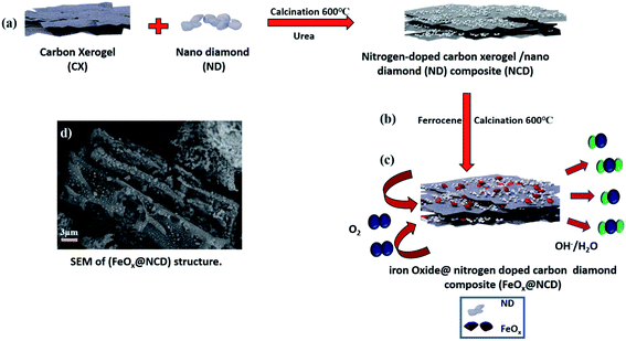
The fabrication process of the FeOx@NCD electrocatalyst is illustrated in Fig. 1. Prior to the synthesis of the catalysts, CX and NCD composites were prepared via the sol–gel polycondensation of resorcinol and formaldehyde, followed by calcination.4 Ferrocene and NCD were uniformly mixed in acetic acid solution. Based on an organometallic ligand-exchange reaction between the carbon substrate and the cyclopentadienyl iron compound via covalent bond formation, the ferrocene is successfully attached to the surface of the carbon via the interaction of the iron atom with the localized π-electrons on the carbon.39 After stirring, the solvent evaporated and the mixture was calcined under a flow of N2 at 600 °C for 2 h to produce FeOx@NCD, which exhibits a sandwich structure of FeOx loaded on both sides of NCD.The surface morphologies of the prepared samples were examined using field-emission SEM (FESEM, Fig. 2a–f). Fig. 2a shows a three-dimensional (3D) interconnected network of CX comprising spherical particles linked to one another, which is in good agreement with the previously published data on typical resorcinol–formaldehyde carbon gels.4 These network structures play a crucial role in achieving high surface accessibility via porous channels as well as exhibiting high electrical conductivity as a result of their connected monolithic walls.40 The ND shown in Fig. 2b displays a continuous nanocluster structure with a grain size of 20–80 nm. Fig. 2c provides evidence that two types of carbon are intimately aggregated together. The CX structure is completely covered with ND in the form of small spherical clusters. Interestingly, Fig. 2d displays a lateral view of the homogenous growth and embedding of pyramidal FeOx crystals on both sides of the NCD surface and in between its matrix. This is assumed to occur due to the rapid binding of the metallic iron originating from ferrocene with the newly produced carbon material (cyclopentadiene) and the NCD. FeOx@NCD exhibits a two-dimensional (2D) planar sheet morphology as a result of its strong π–π stacking, which efficiently prevents the aggregation of FeOx.7 Hence, evenly anchored pyramidal FeOx can be observed on the surface of NCD in the top views shown in Fig. 2e and f. This uniform distribution of FeOx through NCD was further revealed by deep insight into FESEM (Fig. S1a†), wherein numerous FeOx moieties are visible on the underside of the carbon sheet against a semitransparent carbon skeleton, which confirms the encapsulation of FeOx through successive carbon layers, resulting in a fascinating sandwich structure. It can be assumed that this occurs due to the strong covalent interactions between the organometallic ligands and the N-containing groups, effectively preventing the agglomeration of metal species during the pyrolysis process.41 Moreover, the unique NCD structure acts as a carrier to induce the decomposition of ferrocene and to expose more active centers for the high distribution of FeOx, thus resulting in the material exhibiting fast electron and mass transport.42 Such a novel structure favors electrolyte penetration and electron transfer during the ORR. In addition, energy-dispersive X-ray spectroscopy (EDS) elemental mapping images were recorded (Fig. S1b–f†) to further confirm: (i) the successful preparation of the FeOx@NCD composite, (ii) the uniform dispersion of the iron (Fe), carbon (C), nitrogen (N), and oxygen (O) elements in FeOx@NCD, and (iii) the slightly harmonized mapping of the Fe, C, O, and N elements can be observed, further confirming the coordination of Fe with O in an FeOx matrix, and with C in Fe3C.
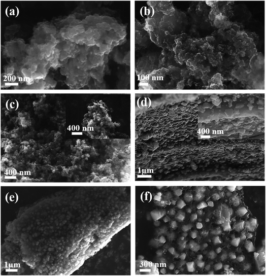 | ||
| Fig. 2 FESEM images of prepared samples of (a) CX, (b) ND, and (c) NCD; and (d) lateral and (e and f) top views of FeOx@NCD. | ||
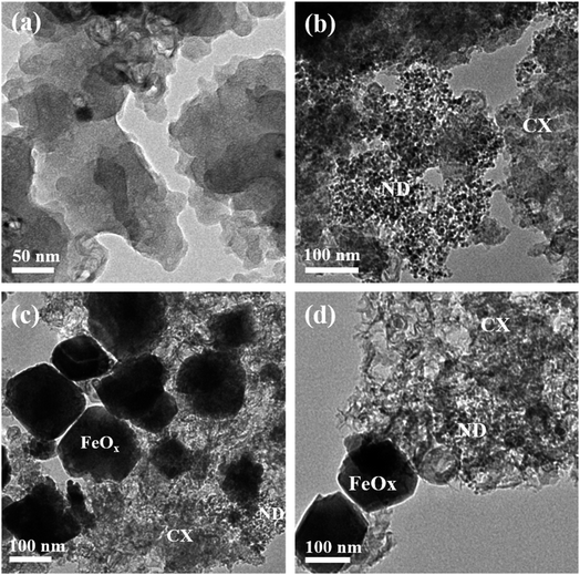
Additionally, the coordination of N with C and Fe proves the successful doping of the FeOx@NCD with N. These observations confirm that the FeOx@NCD electrocatalyst has highly efficient active sites for catalyzing the ORR process. It is clear that the HRTEM images in Fig. 3a–d match the SEM observations. Agglomerated interconnected CX particles with a smooth surface and a uniform distribution of ND in the form of nanospheres with a 4–7 nm diameter on the surface of the CX particles can be seen in Fig. 3a and b, respectively. It can be distinctly observed from Fig. 3a that nanometer-sized cobalt particles, from the catalyst used during the synthesis of CX, are embedded throughout the carbon matrix. The HRTEM images in Fig. 3c and d confirm the growth and anchoring of pyramidal FeOx particles of 80–120 nm in size over the NCD surface. The presence of FeOx and N modulates the charge distribution over the carbon structure and facilitates electron transfer, which results in a superior catalyst material. The doping of N onto the carbon matrix generates positively charged (C+) sites that promote oxygen adsorption.43
The detailed structural features of the prepared materials were examined and the results are shown in Fig. 4. Fig. 4a shows XRD patterns of the CX, NCD and FeOx@NCD. The XRD patterns of CX and NCD display two characteristic graphitic peaks located at 2θ angles of around 26° and 44.25°, which correspond to the (002) and (101) planes of the materials, respectively. The broadness and intensities of these two peaks confirms the amorphous nature of the materials. The XRD peak detected at 51.50° is thought to originate from metallic cobalt.4 The diffraction peaks in Fig. 4a at 30.04° (220), 35.8° (311), 43.5° (400), 53.9° (422), 57.4° (511), 63° (440), and 74.12° (533) can be assigned to FeOx (JCPDS card no. 19 0629). In addition, the small diffraction peaks at 34.08° and 74.53° can be attributed to the characteristic planes of Fe3C, which is in good agreement with FESEM mapping analysis.44–46 These results verify the successful preparation of FeOx (from ferrocene over the surface of NCD in the FeOx@NCD composite.
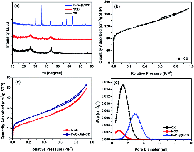 | ||
| Fig. 4 (a) XRD patterns, (b and c) N2 adsorption–desorption isotherms, and (d) pore size distributions of CX, NCD, and FeOx@ NCD. | ||
To investigate the pore structure of the prepared samples, nitrogen adsorption–desorption measurements were recorded at 77 K and pore size distributions were calculated from the obtained isotherms using non-local density functional theory (NLDFT). As shown in Fig. 4b, the adsorption–desorption data of CX closely resembles the type I isotherm of a microporous material. Noticeably, at relatively low pressures of P/P0 < 0.1, a sharp N2 uptake is observed due to the presence of a large number of micropores in CX and the formation of a monolayer. The small contribution of a type II isotherm is evidenced by the increase in gas adsorption above a P/P0 of 0.2, with the presence of a H4 hysteresis loop over a P/P0 range of 0.6–0.9. This observation indicates that the CX contains both microporous and mesoporous structures, which facilitate ionic diffusion inside the carbon matrix. Fig. 4c shows isotherms of NCD and FeOx@NCD, which are mainly type IV isotherms, in which a monolayer and multilayers are formed at low and high relative pressures, respectively. An open H4 hysteresis loop is observed in the isotherm of FeOx@NCD, indicating the development of mesopores in this sample together with the presence of particles with irregular shaped internal voids. As a result, FeOx@NCD exhibits a hierarchical porous structure with a wide pore size distribution spanning both the microporous and mesoporous regions.47,48 As shown in Table 1, FeOx@NCD has a BET surface area (SBET) of 66 m2 g−1 and a total pore volume of 0.024 cm3 g−1. These results were also confirmed via analysis of the obtained isotherms using NLDFT, with the results shown in Fig. 4d. As shown in Table 1, the CX adsorbs the highest volume of gas, suggesting that it has a high surface area and that the majority of its pores are microporous, with the microporous size distributions of CX and NCD being 1.34 and 0.9 nm, respectively. Beyond that, Fig. 4d shows that the mesoporous size distribution of FeOx@NCD is located between the microporous and mesoporous regions in the range of 1.1–5, which confirms that it has both microporous and mesoporous characteristics, with a maximum pore size of around 2.85 nm. Such features are expected to boost the fast transport of electrolyte ions into the exposed active sites and promote the rapid transport of ORR-relevant species. The data obtained from the surface area analysis, i.e., the SBET, pore volume (V0), and pore diameter (L0) over a relative pressure range of 0.02–0.09 are shown in Table 1.
| Sample | S BET | V 0 (N2) | L 0 (N2) | Vp, DFT | L 0 (DFT) |
|---|---|---|---|---|---|
| m2 g−1 | cm3 g−1 | nm | cm3 g−1 | nm | |
| CX | 399 | 0.16 | 1.14 | 0.26 | 1.29 |
| NCD | 52 | 0.02 | 1.66 | 0.04 | 0.73 |
| FeO x @NCD | 66 | 0.03 | 1.56 | 0.06 | 2.85 |
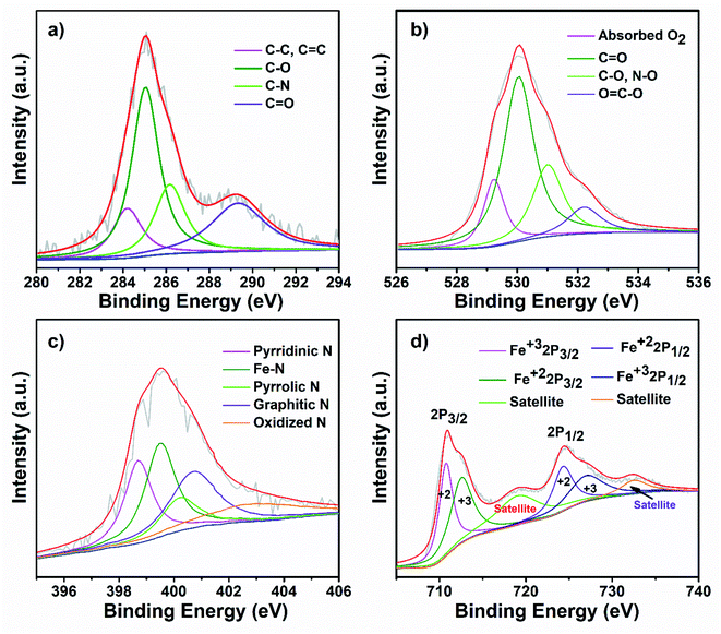
To further investigate the surface chemical state of the as-prepared FeOx@NCD catalyst, XPS measurements were carried out, with the results shown inFig. 5 and S2†. For comparison, the XPS spectra of NCD were also recorded, which are shown in Fig. S3 and S4.† The obvious peaks in the XPS survey spectrum of FeOx@NCD shown in Fig. S2a† at 286, 398, 531, 712, and 785 eV correspond to carbon, nitrogen, oxygen, iron, and cobalt, respectively. The high-resolution C 1s XPS spectrum can be fitted to four peaks, which can be attributed to C–C, C![[double bond, length as m-dash]](https://www.rsc.org/images/entities/char_e001.gif) C (284.60 eV), C–O (285.3), C–N (286.4 eV), and C
C (284.60 eV), C–O (285.3), C–N (286.4 eV), and C![[double bond, length as m-dash]](https://www.rsc.org/images/entities/char_e001.gif) O (288.9 eV) bonding49–51 (Fig. 5a and S4a†). Fig. 5b shows the high-resolution O 1s XPS spectrum of FeOx@NCD, which was fitted to four characteristic oxygen contributions of chemisorbed oxygen at 529.4 eV, lattice oxygen in the Fe–O of Fe3O4 at 530 eV, C
O (288.9 eV) bonding49–51 (Fig. 5a and S4a†). Fig. 5b shows the high-resolution O 1s XPS spectrum of FeOx@NCD, which was fitted to four characteristic oxygen contributions of chemisorbed oxygen at 529.4 eV, lattice oxygen in the Fe–O of Fe3O4 at 530 eV, C![[double bond, length as m-dash]](https://www.rsc.org/images/entities/char_e001.gif) O at 531 eV, and C–O and NO species at 532.4 eV, which differs from the case of NCD.52 The O 1s XPS spectrum of NCD shown in Fig. S4b† exhibits four obvious peaks for chemisorbed oxygen at 529.1 eV; C
O at 531 eV, and C–O and NO species at 532.4 eV, which differs from the case of NCD.52 The O 1s XPS spectrum of NCD shown in Fig. S4b† exhibits four obvious peaks for chemisorbed oxygen at 529.1 eV; C![[double bond, length as m-dash]](https://www.rsc.org/images/entities/char_e001.gif) O at 530 eV; C–O and N–O species at 531.8 eV; and lactone, carboxylic acids, and N–C
O at 530 eV; C–O and N–O species at 531.8 eV; and lactone, carboxylic acids, and N–C![[double bond, length as m-dash]](https://www.rsc.org/images/entities/char_e001.gif) O at 533 eV. Notably, these values indicate a positive shift to higher binding energies upon metalation of NCD with FeOx in FeOx@NCD.53 The presence of N–C
O at 533 eV. Notably, these values indicate a positive shift to higher binding energies upon metalation of NCD with FeOx in FeOx@NCD.53 The presence of N–C![[double bond, length as m-dash]](https://www.rsc.org/images/entities/char_e001.gif) O in the XPS data is clear evidence for the bonding of carbon with nitrogen, which is in good agreement with the C 1s spectra. The nitrogen content in FeOx@NCD is 2.64 wt% which is lower than the 3.64 wt% observed for NCD due to iron doping (Fig. S2a and S3a†). The N 1s spectrum of FeOx@NCD shows peaks at 398.7, 399.5, 400.2, 401, and 402.9 eV, which can be attributed to pyridinic N (21.38 at%), Fe–N (26.31 at%), pyrrolic N (11.51 at%), graphitic N (24.34 at%), and oxidized N (16.44 at%), respectively54 (Fig. 5c and S2b†). The high proportion of Fe–N is clear evidence for the robust binding that takes place between Fe3O4 and NCD. In general, pyridinic N, graphitic N, and Fe–N bonds in carbons are regarded as electroactive sites for the ORR, which enhance the ORR performance.29,49,50,54 The high-resolution N 1s spectrum for the comparative NCD catalyst can also be fitted with several peaks with binding energies of 398.2, 399.7, 400.5, and 403.3 eV (Fig. S4c†), corresponding to pyridinic N (27.11 at%), pyrrolic N (33.89 at%), graphitic N (30.50 at%), and oxidized N (8.47.0 at%), respectively (Fig. S3b†). Fig. 5d shows the Fe 2p XPS spectrum of FeOx@NCD, which features two major peaks at 711.0 and 724.40 eV associated with the Fe 2p3/2 and Fe 2p1/2 core-level binding energies of FeOx on the NCD. In addition, the two peaks located at 718.64 and 732.13 eV represent the shake-up satellites of Fe 2p, which are in good agreement with the values previously reported in the literature.49,50 The two fitted peaks located at 710.74 and 724.30 eV can be attributed to the Fe 2p3/2 and Fe 2p1/2 of Fe2+, whereas the peaks at 712.54 and 726.93 eV can be assigned to the Fe 2p3/2 and Fe 2p1/2 of Fe3+.55
O in the XPS data is clear evidence for the bonding of carbon with nitrogen, which is in good agreement with the C 1s spectra. The nitrogen content in FeOx@NCD is 2.64 wt% which is lower than the 3.64 wt% observed for NCD due to iron doping (Fig. S2a and S3a†). The N 1s spectrum of FeOx@NCD shows peaks at 398.7, 399.5, 400.2, 401, and 402.9 eV, which can be attributed to pyridinic N (21.38 at%), Fe–N (26.31 at%), pyrrolic N (11.51 at%), graphitic N (24.34 at%), and oxidized N (16.44 at%), respectively54 (Fig. 5c and S2b†). The high proportion of Fe–N is clear evidence for the robust binding that takes place between Fe3O4 and NCD. In general, pyridinic N, graphitic N, and Fe–N bonds in carbons are regarded as electroactive sites for the ORR, which enhance the ORR performance.29,49,50,54 The high-resolution N 1s spectrum for the comparative NCD catalyst can also be fitted with several peaks with binding energies of 398.2, 399.7, 400.5, and 403.3 eV (Fig. S4c†), corresponding to pyridinic N (27.11 at%), pyrrolic N (33.89 at%), graphitic N (30.50 at%), and oxidized N (8.47.0 at%), respectively (Fig. S3b†). Fig. 5d shows the Fe 2p XPS spectrum of FeOx@NCD, which features two major peaks at 711.0 and 724.40 eV associated with the Fe 2p3/2 and Fe 2p1/2 core-level binding energies of FeOx on the NCD. In addition, the two peaks located at 718.64 and 732.13 eV represent the shake-up satellites of Fe 2p, which are in good agreement with the values previously reported in the literature.49,50 The two fitted peaks located at 710.74 and 724.30 eV can be attributed to the Fe 2p3/2 and Fe 2p1/2 of Fe2+, whereas the peaks at 712.54 and 726.93 eV can be assigned to the Fe 2p3/2 and Fe 2p1/2 of Fe3+.55
3.2 ORR activity
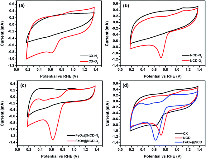
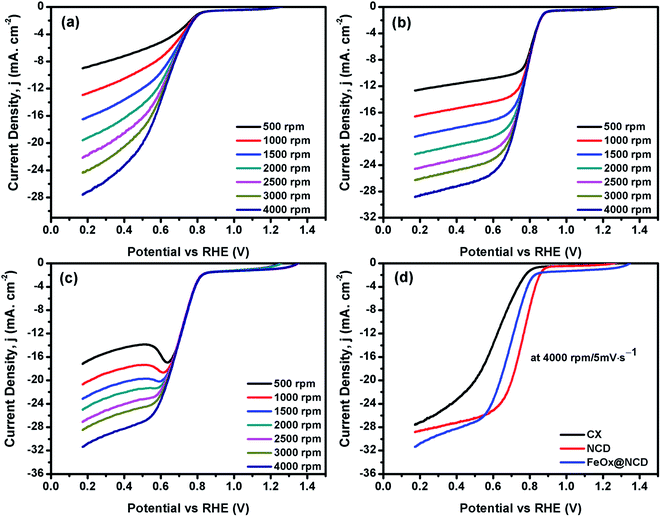
To investigate the electrochemical performance of the electrocatalysts toward the ORR, CV and LSV measurements were performed in O2-saturated 0.1 M KOH electrolyte using an RDE at room temperature. As shown in Fig. 6, the CV measurements were carried out in the presence and absence (i.e., N2-saturated electrolyte) of O2 at 50 mV s−1 to evaluate the activity of the electrocatalysts in the ORR. A shown in Fig. 6a, for N2-saturated electrolyte the obtained CV shows no reduction peak for oxygen, while in O2-saturated electrolyte the CX shows activity for the ORR, evidenced by the presence of a typical oxygen reduction peak at around 0.6 V. As shown in Fig. 6b, the intensity of this peak is increased and shifted to a reduction potential of about 0.7 V in the case of NCD, indicating the higher activity of NCD toward the ORR. This higher activity for NCD can be attributed to two factors. (i) The structure of the ND itself consists of sp3 bonded crystalline diamond in its core and a combination of both sp2 and sp3 bonding in its outer structure. This unique structure of the ND is responsible for facilitating redox reactions under low applied potentials.56 (ii) The presence of pyridinic-N and graphitic-N as dopants in CX promotes the adsorption of oxygen onto the carbon surface by providing positively charged (C+) active sites.57 As shown in Fig. 6c and d, FeOx@NCD exhibits outstanding activity toward the ORR which indicates that Fe plays a key role in the ORR performance via the formation of active centers. Several reports have suggested that the boosting of the ORR activity in the case of Fe and N containing electrocatalysts is due to the formation of Fe–Nx bonds and a charge transfer from Fe to the carbon matrix which in turn enhances the O2 adsorption.41,58 Moreover, the exposed surface area of the sandwich-like architecture of FeOx@NCD offers numerous active sites to the electrolyte and promotes the mass transfer of relevant moieties (e.g., H+/OH− and O2) in the ORR. Overall, these distinctive features make FeOx@NCD a promising ORR catalyst.LSV measurements were recorded using an RDE at a rotation speed in the range of 500–4000 rpm at a scan rate of 5 mV s−1. As shown in Fig. 7(a–d), the obtained LSV data show the same trend as that observed in the CV data. Fig. 7a–c show the LSV data of the CX, NCD, and FeOx@NCD, respectively, recorded at different rotation speeds. As expected, CX and NCD exhibit lower ORR activity than FeOx@NCD. This observation signifies that the formation of Fe-based active centers in this material is essential for catalyzing the ORR.
Fig. 7d shows the LSV data of the electrocatalysts recorded at a rotation speed of 4000 rpm at a scan rate of 5 mV s−1. Although the lowest onset potential for NCD is around 0.89 V vs. RHE which shifts the reaction to a lower potential, the highest limiting current density of −31.5 mA cm−2 at 0.17 V is obtained for FeOx@NCD that indicates its high activity toward the ORR. The calculated half wave potentials, E1/2, for CX, NCD, and FeOx@NCD are 0.628, 0.756, and 0.692 V, respectively, with a positive shift towards NCD of 64 mV.
To evaluate the electron transfer capacity of the electrocatalysts, the obtained LSV data were fitted using the K–L model, as shown in Fig. 8. As revealed from Fig. 8a, great linearity is observed from 0.5 to 0.8 V, demonstrating that the ORR process is a first-order kinetic reaction.41Fig. 8b shows the number of electrons transferred (n) per oxygen molecule calculated from the K–L model. The n values of the CX, NCD, and FeOx@NCD at 0.17 V are 1.7, 2.7, and 4.02, respectively. These results provide evidence that a four-electron transfer mechanism in the ORR process is dominant for FeOx@NCD.
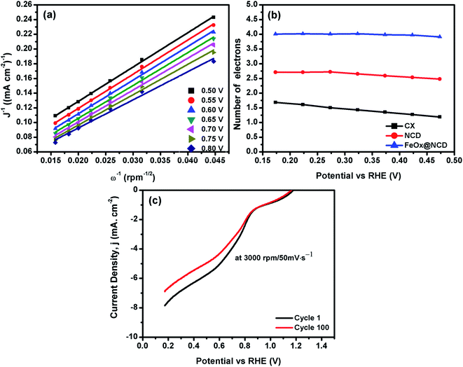 | ||
| Fig. 8 (a) Linear K–L plots of FeOx@NCD from 0.5 to 0.8 V, (b) the n values of the electrocatalysts, and (c) the 1st and 100th cycles of FeOx@NCD recorded at 3000 rpm at a scan rate of 50 mV s−1. | ||
The stability of the FeOx@NCD catalyst is another important factor that needs to be taken into consideration, which was further examined by carrying out LSV measurements at 3000 rpm and a scan rate of 50 mV s−1 for 100 cycles, with the results shown in Fig. 8d. The retention of around 87.3% of the current density is achieved after 100 working cycles, with the slight drop of 12.7% attributed to the consumption of oxygen from the electrolyte during the measurements. Remarkably, the FeOx@NCD electro-catalyst shows higher ORR catalytic activity with already published ones in the same alkaline medium, higher limiting current density is obtained with lower half wave potentials, E1/2and the number of transferred electrons is almost four for all electro-catalysts which is the favored pathway for ORR, Table 2.
| Electro-catalyst | Electrolyte | E 1/2, V | No. of e− | Current Density | Reference |
|---|---|---|---|---|---|
| (RHE) | mA cm−2 | ||||
| FeOx@NCD | 0.1 M KOH | 0.692 | 4.02 | −31.50 | This work |
| Fe3C–Fe,N/CFe1.6–N– | 0.1 M KOH | 0.881 | 3.97 | −5.50 | 13 |
| HCNS/rGO | 0.1 M KOH | 0.872 | 4.02 | −5.58 | 59 |
| Fe–N/C | 0.1 M KOH | 0.812 | 4.08 | −5.98 | 60 |
| Fe2+@NCS-A | 0.1 M KOH | 0.790 | 3.70 | −4.01 | 61 |
| Fe-ND/C | 0.1 M KOH | 0.790 | 4.30 | −5.50 | 62 |
4. Conclusions
A versatile and simple synthetic strategy was developed for decorating an NCD matrix with a pyramidal FeOx nanostructure to form an FeOx@NCD electrocatalyst. Using ferrocene pyrolysis, a structure of uniformly dispersed FeOx crystals embedded between carbon matrix layers was produced. The rich nitrogen and FeOx content in FeOx@NCD combined with the typical structural features of a carbon matrix results in the material exhibiting a large accessible surface area with ideal porosity, rapid mass transfer, and easily accessible active sites for excellent catalytic performance in the ORR. FeOx@NCD exhibits the best ORR performance among all of the currently reported electrocatalysts and shows robust long-term stability in 0.1 M KOH solution. In terms of practical application, it is hoped that these findings will inspire the utilization of this synthetic route for the preparation of other MO-modified carbon electrocatalysts that exhibit excellent ORR performance.Author contributions
Conceptualization, A. E. A. and A. A.; methodology, A. E. A. and A. A.; validation, A. A. F.; formal analysis, A. A. F.; investigation, A. A.; data curation, A. A. F.; writing – original draft preparation, A. E. A. and A. A.; writing – review and editing, A. A.; visualization, A. A. F.; supervision, A. E. A. and A. A. F.; project administration, A. A.; funding acquisition, A. A. F. All authors have read and agreed to the published version of the manuscript.Conflicts of interest
There are no conflicts to declare.References
- H. Tan, J. Tang, J. Kim, Y. V. Kaneti, Y. M. Kang, Y. Sugahara and Y. Yamauchi, J. Mater. Chem. A, 2019, 7, 1380–1393 RSC.
- C. Hu, Y. Xiao, Y. Zou and L. Dai, Electrochem. Energy Rev., 2018, 1, 84–112 CrossRef CAS.
- J. Fan, M. Chen, Z. Zhao, Z. Zhang, S. Ye, S. Xu, H. Wang and H. Li, Nat. Energy, 2021, 6, 475–486 CrossRef CAS.
- A. Abdelwahab, J. Castelo-Quibén, M. Pérez-Cadenas, A. Elmouwahidi, F. J. Maldonado-Hódar, F. Carrasco-Marín and A. F. Pérez-Cadenas, Catalysts, 2017, 7, 1–13 CrossRef.
- S. Zaman, L. Huang, A. I. Douka, H. Yang, B. You and B. Y. Xia, Angew. Chem., Int. Ed., 2021, 133(33), 17976–17996 CrossRef.
- S. Wang, X. Ji, Y. Ao and J. Yu, ACS Appl. Mater. Interfaces, 2018, 10, 29866–29875 CrossRef CAS PubMed.
- Z. K. Yang, L. Lin and A. W. Xu, Small, 2016, 12, 5710–5719 CrossRef CAS PubMed.
- A. Zadick, L. Dubau, N. Sergent, G. Berthomé and M. Chatenet, ACS Catal., 2015, 5, 4819–4824 CrossRef CAS.
- Y. Wu, J. Zang, L. Dong, Y. Zhang and Y. Wang, J. Power Sources, 2016, 305, 64–71 CrossRef CAS.
- C. Li, H. Tan, J. Lin, X. Luo, S. Wang, J. You, Y. M. Kang, Y. Bando, Y. Yamauchi and J. Kim, Nano Today, 2018, 21, 91–105 CrossRef CAS.
- A. Abdelwahab, F. Carrasco-Marín and A. F. Pérez-Cadenas, Mater., 2019, 12, 2446–2463 CrossRef CAS PubMed.
- Z. A. C. Ramli and S. K. Kamarudin, Nanoscale Res. Lett., 2018, 13, 410 CrossRef CAS PubMed.
- H. Tan, Y. Li, J. Kim, T. Takei, Z. Wang, X. Xu, J. Wang, Y. Bando, Y. M. Kang, J. Tang and Y. Yamauchi, Adv. Sci., 2018, 5, 1800120 CrossRef PubMed.
- G. Zhang, B. Y. Xia, C. Xiao, L. Yu, X. Wang, Y. Xie and X. W. (David) Lou, Angew. Chem., Int. Ed., 2013, 52, 8643–8647 CrossRef CAS PubMed.
- Y. Liu, T. G. Kelly, J. G. Chen and W. E. Mustain, ACS Catal., 2013, 3, 1184–1194 CrossRef CAS PubMed.
- H. Zhang, W. Xia, H. Shen, W. Guo, Z. Liang, K. Zhang, Y. Wu, B. Zhu and R. Zou, Angew. Chem., Int. Ed., 2020, 59, 1871–1877 CrossRef CAS PubMed.
- J. C. Li, P. X. Hou and C. Liu, Small, 2017, 13, 1–13 Search PubMed.
- E. Y. Choi and C. K. Kim, Sci. Rep., 2017, 7, 1–9 CrossRef PubMed.
- B. Huang, L. Peng, F. Yang, Y. Liu and Z. Xie, J. Energy Chem., 2017, 26, 712–718 CrossRef.
- A. F. Zainul Abidin, K. S. Loh, W. Y. Wong and A. B. Mohamad, Int. J. Hydrogen Energy, 2019, 44, 28789–28802 CrossRef CAS.
- D. Sebastián, C. Alegre, M. E. Gálvez, R. Moliner, M. J. Lázaro, A. S. Aricò and V. Baglio, J. Mater. Chem. A, 2014, 2, 13713–13722 RSC.
- C. Wang, J. Kim, J. Tang, J. Na, Y. M. Kang, M. Kim, H. Lim, Y. Bando, J. Li and Y. Yamauchi, Angew. Chem., Int. Ed., 2020, 59, 2066–2070 CrossRef CAS PubMed.
- N. Zhou, N. Wang, Z. Wu and L. Li, Catalysts, 2018, 8(11), 509 CrossRef.
- R. Shibuya, T. Kondo and J. Nakamura, Carbon-Based Met. Catal. Des. Appl., 2018, 1–2, 227–249 Search PubMed.
- H. Zhang, X. Wang, Z. Li, C. Zhang and S. Liu, Nanoscale, 2021, 13, 17663–17674 RSC.
- A. Enaiet Allah, H. Tan, X. Xu, A. A. Farghali, M. H. Khedr, A. A. Alshehri, Y. Bando, N. A. Kumar and Y. Yamauchi, Nanoscale, 2018, 10, 12398–12406 RSC.
- H. Tan, J. Kim, J. Lin, C. Li, S. M. Alsheri, T. Ahamad, N. Alhokbany, Y. Bando, M. Zaman, M. S. A. Hossain, S. Wang and Y. Yamauchi, Microporous Mesoporous Mater., 2019, 280, 1–6 CrossRef CAS.
- C. Wei, H. Wang, K. Eid, J. Kim, J. H. Kim, Z. A. Alothman, Y. Yamauchi and L. Wang, Chem.–Eur. J., 2017, 23, 637–643 CrossRef CAS PubMed.
- K. Wang, H. Chen, X. Zhang, Y. Tong, S. Song, P. Tsiakaras and Y. Wang, Appl. Catal., B, 2020, 264, 118468 CrossRef.
- Q. Xie, W. Si, Y. Shen, Z. Wang and H. Uyama, Nanoscale, 2021, 13, 16296–16306 RSC.
- Y. Wang, Y. Wang, J. Zang, L. Dong, H. Pan and Y. Yuan, Electrochim. Acta, 2013, 113, 583–590 CrossRef CAS.
- Y. Zhang, K. Y. Rhee, D. Hui and S. J. Park, A Critical Review of Nanodiamond Based Nanocomposites: Synthesis, Properties and Applications, Elsevier Ltd, 2018, vol. 143 Search PubMed.
- Y. Liu, S. Chen, X. Quan and H. Yu, J. Am. Chem. Soc., 2015, 137, 11631–11636 CrossRef CAS PubMed.
- D. Banerjee, K. J. Sankaran, S. Deshmukh, M. Ficek, G. Bhattacharya, J. Ryl, D. M. Phase, M. Gupta, R. Bogdanowicz, I. N. Lin, A. Kanjilal, K. Haenen and S. S. Roy, J. Phys. Chem. C, 2019, 123, 15458–15466 CrossRef CAS.
- Y. Lin, X. Sun, D. S. Su, G. Centi and S. Perathoner, Chem. Soc. Rev., 2018, 47, 8438–8473 RSC.
- H. Wang, W. Wang, Y. Y. Xu, S. Dong, J. Xiao, F. Wang, H. Liu and B. Y. Xia, ACS Appl. Mater. Interfaces, 2017, 9, 10610–10617 CrossRef CAS PubMed.
- Z. Xiao, F. Hou, Y. Li, R. Zhang, G. Shen, L. Wang, X. Zhang, Q. Wang and G. Li, Chem. Eng. Sci., 2019, 207, 235–246 CrossRef CAS.
- S. Zhu, H. Tian, N. Wang, B. Chen, Y. Mai and X. Feng, Small, 2018, 14, 1702755 CrossRef PubMed.
- Q. Dong, X. Zhuang, Z. Li, B. Li, B. Fang, C. Yang, H. Xie, F. Zhang and X. Feng, J. Mater. Chem. A, 2015, 3, 7767–7772 RSC.
- M. A. Wasfey, A. Abdelwahab, F. Carrasco-Marín, A. F. Pérez-Cadenas, H. H. Abdullah, I. S. Yahia and A. A. Farghali, Mater., 2020, 13, 1–16 Search PubMed.
- N. Shang, C. Wang, X. Zhang, S. Gao, S. Zhang, T. Meng, J. Wang, H. Wang, C. Du, T. Shen, J. Huang, Y. Qiao, Q. Wu and Y. Gao, Chem. Eng. J., 2021, 426, 127345 CrossRef CAS.
- T. Gao, C. Zhou, Y. Zhang, Z. Jin, H. Yuan and D. Xiao, J. Mater. Chem. A, 2018, 6, 21577–21584 RSC.
- V. Premkumar, N. Chandrasekaran, K. Madasamy, M. Kathiresan, P. Kanagavalli and S. Senthil Kumar, New J. Chem., 2018, 42, 15629–15638 RSC.
- Z. Liu, Y. Zhong, B. Sun, X. Liu, J. Han, T. Shi, Z. Tang and G. Liao, ACS Appl. Mater. Interfaces, 2017, 9, 22361–22368 CrossRef CAS PubMed.
- D. Amara, J. Grinblat and S. Margel, J. Mater. Chem., 2012, 22, 2188–2195 RSC.
- Y. Chen, X. F. Zhang, A. J. Wang, Q. L. Zhang, H. Huang and J. J. Feng, Microchim. Acta, 2019, 186, 660 CrossRef PubMed.
- I. Union, O. F. Pure and A. Chemistry, Pure Appl. Chem., 1985, 57, 603–619 Search PubMed.
- K. V. Kumar, S. Gadipelli, B. Wood, K. A. Ramisetty, A. A. Stewart, C. A. Howard, D. J. L. Brett and F. Rodriguez-Reinoso, J. Mater. Chem. A, 2019, 7, 10104–10137 RSC.
- Y. Li, Y. Kong, Y. Hou, B. Yang, Z. Li, L. Lei and Z. Wen, ACS Sustainable Chem. Eng., 2019, 7, 8853–8859 CrossRef CAS.
- B. Zhang, J. Chen, H. Guo, M. Le, H. Guo, Z. Li and L. Wang, ACS Appl. Nano Mater., 2021, 4, 8360–8367 CrossRef CAS.
- A. E. Allah, J. Wang, Y. V. Kaneti, T. Li, A. A. Farghali, M. H. Khedr, A. K. Nanjundan, B. Ding, H. Dou, X. Zhang, B. Yoshio and Y. Yamauchi, Nano Energy, 2019, 65, 103991 CrossRef CAS.
- Z. Xiao, G. Xiao, M. Shi and Y. Zhu, ACS Appl. Mater. Interfaces, 2018, 10, 16436–16448 CrossRef CAS PubMed.
- T. Marshall-Roth, N. J. Libretto, A. T. Wrobel, K. J. Anderton, M. L. Pegis, N. D. Ricke, T. Van Voorhis, J. T. Miller and Y. Surendranath, Nat. Commun., 2020, 11, 1–14 Search PubMed.
- G. Ye, K. Zhao, Z. He, R. Huang, Y. Liu and S. Liu, ACS Sustainable Chem. Eng., 2018, 6, 15624–15633 CrossRef CAS.
- X. Yang, C. Li, J. Huang, Y. Liu, W. Chen, J. Shen, Y. Zhu and C. Li, RSC Adv., 2017, 7, 15168–15175 RSC.
- A. Krueger, in Nanodiamond, ed. O. A. Williams, 2014, pp. 49–88 Search PubMed.
- F. Xiao, G. L. Xu, C. J. Sun, M. Xu, W. Wen, Q. Wang, M. Gu, S. Zhu, Y. Li, Z. Wei, X. Pan, J. Wang, K. Amine and M. Shao, Nano Energy, 2019, 61, 60–68 CrossRef CAS.
- Y. Cheng, S. He, S. Lu, J.-P. Veder, B. Johannessen, L. Thomsen, M. Saunders, T. Becker, R. De Marco, Q. Li, S. Yang and S. P. Jiang, Adv. Sci., 2019, 6, 1802066 CrossRef PubMed.
- H. Tan, J. Tang, J. Henzie, Y. Li, X. Xu, T. Chen, Z. Wang, J. Wang, Y. Ide, Y. Bando and Y. Yamauchi, ACS Nano, 2018, 12, 5674–5683 CrossRef CAS PubMed.
- H. Tan, Y. Li, X. Jiang, J. Tang, Z. Wang, H. Qian, P. Mei, V. Malgras, Y. Bando and Y. Yamauchi, Nano Energy, 2017, 36, 286–294 CrossRef CAS.
- J. Feng, R. Cai, E. Magliocca, H. Luo, L. Higgins, G. L. F. Romario, X. Liang, A. Pedersen, Z. Xu, Z. Guo, A. Periasamy, D. Brett, T. S. Miller, S. J. Haigh, B. Mishra and M. M. Titirici, Adv. Funct. Mater., 2021, 31, 2102974 CrossRef CAS.
- P. Su, W. Huang, J. Zhang, U. Guharoy, Q. Du, Q. Sun, Q. Jiang, Y. Cheng, J. Yang, X. Zhang, Y. Liu, S. P. Jiang and J. Liu, Nano Res., 2020, 144(14), 1069–1077 Search PubMed.
Footnote |
| † Electronic supplementary information (ESI) available. See DOI: 10.1039/d1na00776a |
| This journal is © The Royal Society of Chemistry 2022 |

