
 Open Access Article
 This Open Access Article is licensed under a Creative Commons Attribution-Non Commercial 3.0 Unported Licence
Three interfaces of the dental implant system and their clinical effects on hard and soft tissues
Jeong Chan
Kim
 a,
Min
Lee
b and
In-Sung Luke
Yeo
*c
a,
Min
Lee
b and
In-Sung Luke
Yeo
*c
aDepartment of Periodontology, Seoul National University School of Dentistry, Seoul 03080, Korea
bDepartment of Bioengineering, University of California, Los Angeles, CA 90095, USA
cDepartment of Prosthodontics, School of Dentistry and Dental Research Institute, Seoul National University, 101 Daehak-Ro, Jongro-Gu, Seoul 03080, Korea. E-mail: pros53@snu.ac.kr; Fax: +82-2-2072-3860; Tel: +82-2-2072-2661
First published on 4th March 2022
Abstract
Anatomically, the human tooth has structures both embedded within and forming part of the exterior surface of the human body. When a tooth is lost, it is often replaced by a dental implant, to facilitate the chewing of food and for esthetic purposes. For successful substitution of the lost tooth, hard tissue should be integrated into the implant surface. The microtopography and chemistry of the implant surface have been explored with the aim of enhancing osseointegration. Additionally, clinical implant success is dependent on ensuring that a barrier, comprising strong gingival attachment to an abutment, does not allow the infiltration of oral bacteria into the bone-integrated surface. Epithelial and connective tissue cells respond to the abutment surface, depending on its surface characteristics and the materials from which it is made. In particular, the biomechanics of the implant–abutment connection structure (i.e., the biomechanics of the interface between implant and abutment surfaces, and the screw mechanics of the implant–abutment assembly) are critical for both the soft tissue seal and hard tissue integration. Herein, we discuss the clinical importance of these three interfaces: bone–implant, gingiva–abutment, and implant–abutment.
 Jeong Chan Kim | Jeong Chan Kim is currently a chief technical officer in an implant manufacturing company, Deep Implant System, Seongnam, Korea. He graduated from Seoul National University, Seoul, Korea, and received his master's degree in Periodontology at the same university. He is a periodontologist and was a clinical adjunct professor in the department of Periodontology at Seoul National University School of Dentistry. He is now working on the development of modified implant surfaces. |
 Min Lee | Min Lee is a professor in the School of Dentistry and affiliated faculty in the department of Bioengineering at the University of California, Los Angeles. He received his PhD in biomedical engineering from UCLA and joined the faculty of UCLA in 2007. Dr Lee's research focuses on the design and development of new biomaterial systems to provide fundamental bases and translational approaches to tissue engineering and regenerative medicine. Specific areas of interest are orthobiologics, material-based therapeutics to repair craniofacial and orthopedic skeletal defects, novel liposomal platform for drug and gene delivery, injectable hydrogel systems. |
 In-Sung Luke Yeo | In-Sung Luke Yeo is currently a professor at Seoul National University, Seoul, Korea. He served as a dental officer at Special Forces Commands in the Korean Army from the year 2003 to 2006. He completed his PhD in the department of Prosthodontics at Seoul National University School of Dentistry where his theme was on implant surface modification and bone-implant interface. He is treating patients as a prosthodontist at Seoul National University Dental Hospital, and is investigating the nature of hard and soft tissue responses to implant surfaces. |
1. Introduction
An endosteal dental implant is an artificial biomedical device that is surgically installed and anchored to the jaw bone to support a supra-structure (an implant-supported prosthesis) as a replacement for missing teeth.1 Teeth perform three main functions: mastication, speech, and esthetics (beauty), and loss of teeth can compromise these. Traditionally, dental clinicians have treated tooth loss using fixed or removable prostheses that are associated with the remaining teeth; however, with this type of prosthesis, the remaining teeth can be damaged by the various forces applied to the prosthesis.2–4 Therefore, restoration using dental implants is preferred as a first prosthetic option, and dental implants are now the mainstream in modern clinical dentistry.A tooth consists of a crown that projects into the oral area through the gingiva (gum) and is visible in the mouth, and a root that is submerged in the jaw bone. The structure of a dental implant system is similar to that of a tooth, where the implant is the counterpart of the root and the artificial crown is equivalent to a natural crown; however, the root and crown of a tooth form a single continuous structure, while the implant and artificial crown in an implant system are separate parts interconnected by the abutment (Fig. 1).
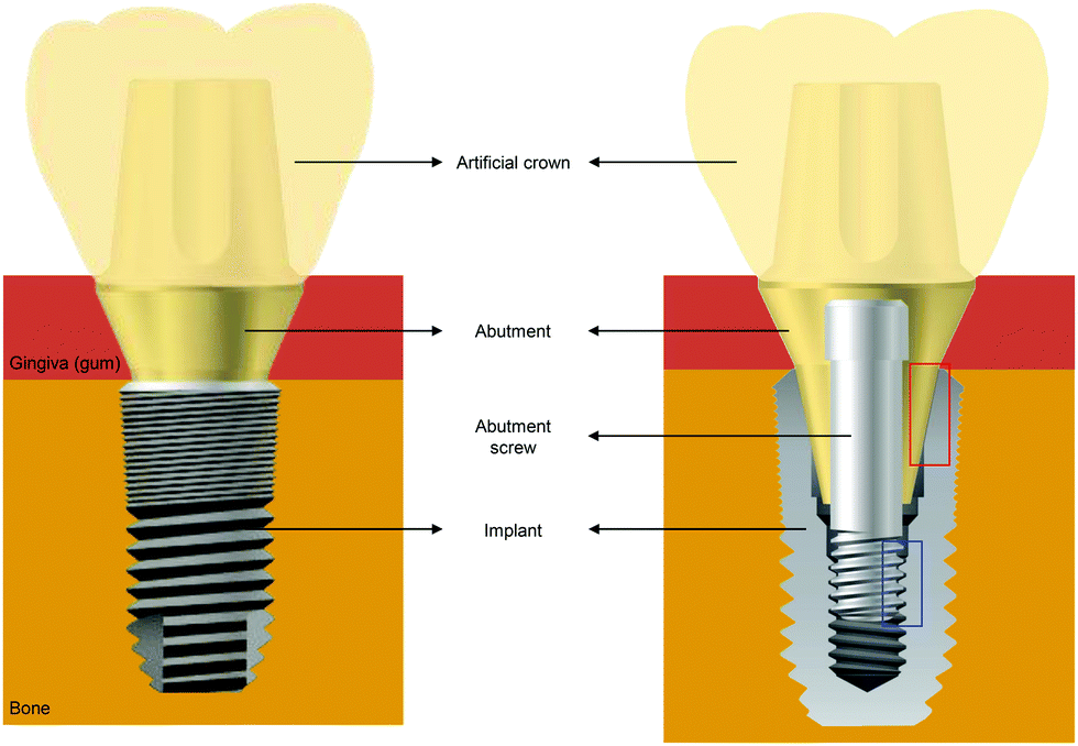 | ||
| Fig. 1 Basic structure of a dental implant system. The abutment is connected to the implant by an abutment screw. In this example, the artificial crown is cemented to the abutment. The cross-sectional diagram on the right shows an implant–abutment interface, which is composed of a frictional interface between two inclined planes (red rectangle) and a screw interface (blue rectangle). | ||
An implant, an abutment, and an artificial crown are the three major components of a dental implant system. As implants are placed into the jaw bone and abutments are located in the soft tissue (gingiva) area between the jaw bone and the mouth, dental implant systems have two biological interfaces: a hard tissue–implant interface and a soft tissue–abutment interface. The bone should be integrated into the implant surface to rehabilitate missing teeth, while the gingiva should be firmly attached to the abutment surface to inhibit inflammatory responses around the implant system.5–7 The implant–abutment interface (Fig. 1) should also be considered, and its biomechanical characteristics strongly influence bone and gingiva physiology.
This review explores the interactive effects of the hard tissue–implant, soft tissue–abutment, and implant–abutment interfaces, which have not been covered in previous reviews, from a clinical perspective. In the first section, we discuss topographically or chemically modified implant surfaces affecting bone healing at the hard tissue–implant interface. In the second section, we search the clinical meaning of the soft tissue seal around abutments, discussing abutment material and design factors influencing the attachment between soft tissues and abutments. In the third section, we investigate some biomechanical formulas analyzing two typical implant–abutment connection structures, and clinically interpret material features and limitations that these formulas imply.
2. Bone–implant interface (hard tissue integration)
2.1. Hard tissue integration (osseointegration)
Mastication involves use of the teeth, jaw bone, and masticatory muscles, and dental implants replace the function of teeth. Therefore, implants must be strongly anchored to the jaw bone to fulfil their masticatory role; this is referred to as hard tissue integration.6,7 When an implant is inserted into the bone, the initial stability of the implant depends on the mechanical surface contact between the bone and the implant, referred to as ‘primary stability’.8 This physical contact can be described using the well-known mass-spring-damper model of mechanical vibration, based on the second-order differential equation,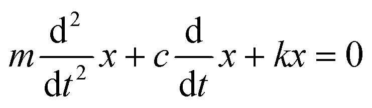 , where m is the mass of the system, c is the damping constant, k is the spring constant, x is displacement, and t is time.9 As the process of bone healing progresses, hard tissue integration occurs at the bone–implant interface, giving the implant secondary stability, which increases implant anchorage to the bone; this biological phenomenon complicates the mechanical interpretation of implant stability.8,10
Hard tissue integration, commonly called osseointegration, has been defined as ‘a direct contact between a loaded implant surface and bone at the light microscopic level of resolution’6 (Fig. 2); however, by this definition, hard tissue integration can only be observed and described using histological methods; hence the definition has been modified to be more clinically relevant. An example modified definition is ‘a clinically asymptomatic rigid fixation of alloplastic materials achieved and maintained in bone during functional loading’.11 Recently, Albrektsson et al. suggested that commercially pure Ti might act as a foreign body when placed in living tissues; hence hard tissue integration can be considered as an immune-modulated inflammatory process.12 Conversely, a previous in vivo study predicted the possibility of a non-physical, bio-affinitive bond between Ti and bone.13 The nature of interaction between bone and biocompatible implant surfaces, including Ti and zirconium dioxide (zirconia, ZrO2), remains incompletely understood.
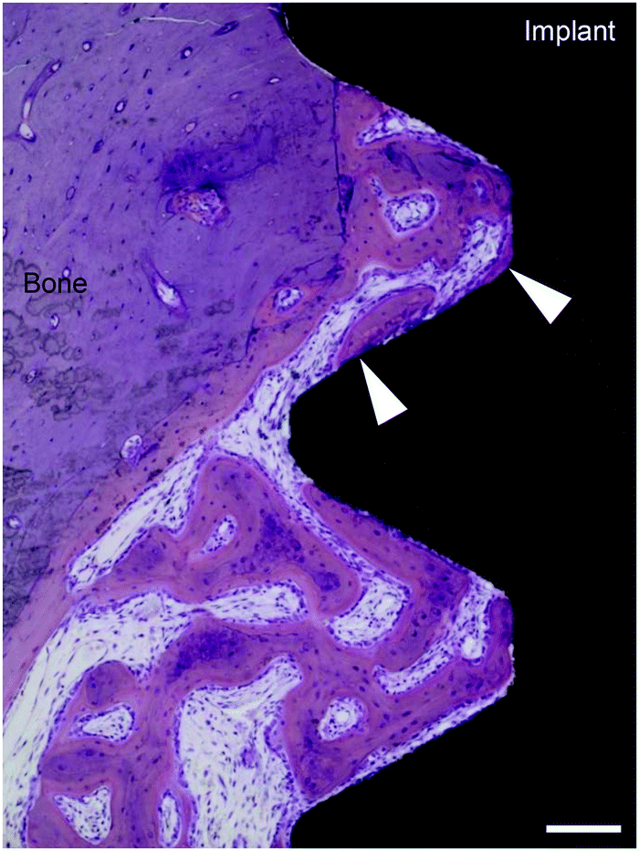 | ||
| Fig. 2 Hard tissue integration (undecalcified section, stained with hematoxylin and eosin). The bone, in direct contact with the implant surface (white arrowheads), is shown in this histological image. Scale bar = 100 μm. | ||
When an implant is inserted into a hole in the bone during implant surgery, water and ions come into contact with the implant surface during bleeding. As bleeding and hemostasis proceed, extracellular matrix (ECM) proteins mediate cell attachment to cover the surface.14 Inflammation occurs and subsides, and granulation tissue formation and angiogenesis follow.15 Osteoprogenitor cells adhere to the implant surface via the ECM proteins and differentiate into osteoblasts, which form new bone at the bone–implant interface.14 Initially, the new bone is woven bone, which is replaced by lamellar bone, depending on load distribution and the resulting bone strain at the bone–implant interface.15,16 Osteoclasts absorb the woven bone, forming resorbed depressions called Howship's lacunae. Osteoblast precursor cells detect the texture of this resorbed bone surface using pseudopodia, acquiring information on the quantity of bone needed to fill the lacunae.17 Topographical modification of the implant surface to generate a texture similar to the lacunae is believed to enhance osteoblast bone formation activity.18,19
Dental implants made of Ti, particularly those made with commercially pure Ti, are widely used to replace lost teeth. Long-term successful clinical results (i.e., >10 years) have been achieved with Ti dental implants.6 Ti is a biologically stable metal that is inert and consistent, and does not activate biocompatible responses or foreign-body reactions when inserted in the human body.20,21 Hard tissue integration allows implants to act as load-bearing structures. As implants are in direct contact with the surrounding bone, the stress applied on artificial crowns is transferred and distributed from abutments and implants to the underlying bone. A macroscopic design should be incorporated into implants to facilitate effective transfer of force to the bone and effective conversion of shear force to compressive force.5 A representative example of such macroscopic design is a thread, and screw-shaped implants have been very successful clinically.5,6
Nevertheless, microscopic modifications of implant surfaces are necessary to accelerate hard tissue integration and reduce the duration of edentulous periods for patients, since most are aged, with consequent slow bone metabolism.7,14 Bone response at the bone–implant interface plays a significant role in successful osseointegration, as demonstrated by in vivo studies showing that microchanges or nanochanges on the surfaces of Ti dental implants influence bone reactions.7,22–25 Several studies have reported the effects of altering implant surfaces on accelerating and strengthening bone healing, allowing more rapid delivery of an implant-supported prosthesis to the patient.25 Various types of surface treatment improve surface biocompatibility and bone regeneration around the dental implant, resulting in rapid hard tissue integration.22,24,26–31
Surface modification is achieved at the microscale or nanoscale. At the microscale, the surface of the implant is mainly modified topographically, usually to mimic the lacunae.19 The roughness and morphology of this micro-topographically altered surface can be revealed by scanning electron microscopy (SEM).14 At the nanoscale, treatment involves biochemical alteration of the implant surface (e.g., application of molecules with affinity for osteogenic cells).7,25 Surface control at the nanoscale is usually undetectable by SEM, because nanomodification has little effect on surface micromorphology;25,32 however, for unknown reasons, osteogenic cells behave quite differently on nanomodified surfaces than on surfaces without nanomodification.32
Two important micro-topographically altered surfaces are established for use in the clinic: the sandblasted, large-grit, acid-etched (SLA) surface and the oxidized Ti surface. Implant surfaces can also be modified chemically by adding calcium (Ca) and phosphorus (P), the major elements of bone, or with trace amounts of fluoride, and these types of nano-modified surfaces have been successfully implemented in the clinic.
2.2. Modifications of surface topography
The turned surface of a Ti dental implant does not undergo a modification process. Computer numerical controlled milling for surface machining yields various characteristics on this surface, such as machining grooves on a smooth surface (Fig. 3A). As mentioned above, a surface with Sa < 0.5 μm is classified as smooth. Although Ti dental implants with this type of surface yield successful long-term clinical results for restoration of missing teeth, a long period of time is required for osseointegration to occur prior to loading.34 Consequently, turned surfaces are used as controls in many laboratory and clinical investigations to assess the qualities of modified surfaces.14,24,30
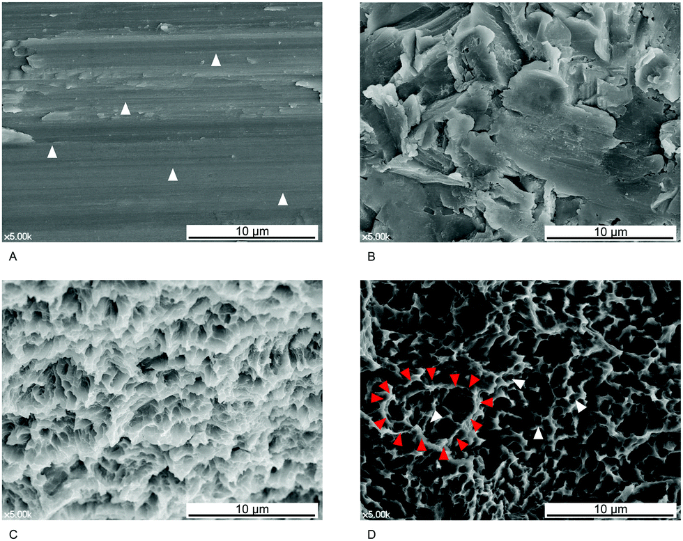 | ||
| Fig. 3 (A) Scanning electron microscopy (SEM) image of turned Ti. The process of machining via computer numerical control milling yields characteristic grooves (white arrowheads). (B) SEM image of a blasted Ti surface. Many irregularities are formed during the blasting procedure. The surface morphology is affected by the diameter of the blast media (here, approximately 50 μm), the type of media (here, Al2O3), and the blasting pressure. In general, the irregularities are larger than those formed during etching. (C) SEM image of a Ti surface modified by acid etching showing small honeycomb-shaped irregularities resulting from the etching process. (D) Ti surface sandblasted with large particles (here, approximately 75 μm), followed by acid etching (Deep Implant System, Inc., Seongnam, Korea) imaged by SEM. The irregularities include large crater-like structures created during the blasting process (red arrowheads) and small honeycomb-shaped micropits (white arrowheads) produced by application of acids to the surface. | ||
The surface of implants can be topographically modified by physical blasting (or grit blasting) with specific particles, called blast media. The most commonly used blast media in dental implantology are aluminum oxide (Al2O3), Ti dioxide (TiO2), and CaP particles (Fig. 3B).25 Various factors influence the resultant roughness, including the size of the particles, the duration of blasting, pressure, and the distance from the particle nozzle to the surface.14,25 The optimal blasted surface with the best removal torque and bone-to-implant contact (BIC) is classified as moderately rough, with an Sa of approximately 1.5 μm.35 Surface etching of Ti dental implants is commonly achieved using hydrochloric acid, sulfuric acid, and hydrofluoric acid (HF).25 Commercially pure Ti contains trace impurities that are acid-labile, while elemental Ti is resistant to corrosion by acid; therefore, when a Ti implant is immersed in an acidic solution, the acid can cause erosion and formation of surface pits. Acidic solution type, concentration, temperature, and etching period can all influence the microstructure of the etched surface.14 The diameter of the pits produced in this manner is typically 0.5–2 μm (Fig. 3C), and the Sa value of the etched surface is <1.0 μm.14 Consequently, the surface may be smooth or minimally rough.
The surface of a Ti dental implant can be sandblasted with large grit particles (75–500 μm in size) and then immersed in an acidic solution for etching, yielding an SLA surface (Fig. 3D).7,19,25 SLA surfaces have been widely used in clinical dentistry for many years; however, the resultant surfaces differ topographically depending on the conditions used for etching and blasting.19,22,24 Bone formation activity of osteogenic cells on an SLA surface is believed to depend on the microtopographical similarity of the surface to the lacuna, the site where osteoclasts resorb the bone.19 Most previous studies have described SLA surfaces as moderately rough, and more biocompatible than surfaces that are only etched or blasted.36,37 Therefore, SLA surfaces serve as positive controls in studies evaluating new modified surfaces.38–41
Another type of SLA surface used in clinical dentistry has additional hydrophilic properties, and is called a hydrophilic SLA or modified SLA (modSLA) surface. An SLA surface with no additional hydrophilicity is considered a standard or hydrophobic SLA surface. To make a standard SLA surface hydrophilic, it is rinsed in water under nitrogen protection and stored in isotonic NaCl solution without atmospheric contact.42 Implants with hydrophilic SLA surfaces are similar to those with standard SLA in terms of topography (Fig. 4A) (i.e., they have moderate roughness); however, a few studies have reported modSLA surfaces with Sa > 2.0 μm, which were therefore classified as rough.23,43
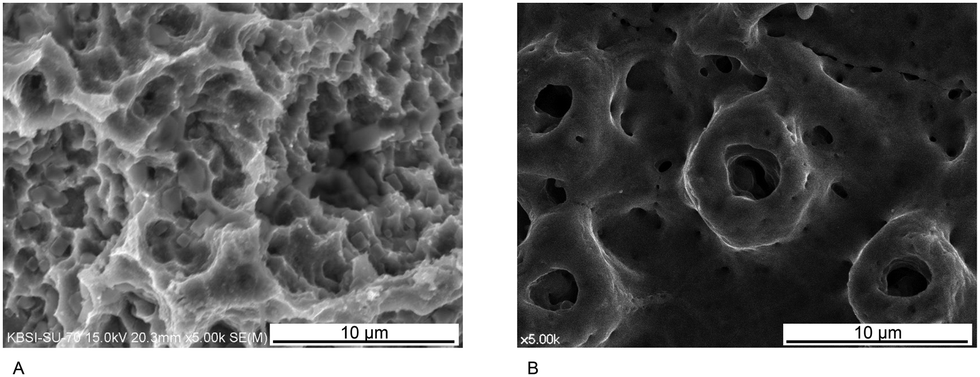 | ||
| Fig. 4 (A) Scanning electron microscopy (SEM) image of a hydrophilic SLA surface (SLActive, Institute Straumann AG, Basel, Switzerland). There are no distinct differences in specific SEM features between hydrophilic and standard SLA surfaces. (B) SEM images of an anodically oxidized Ti surface (TiUnite, Nobel Biocare, Zürich, Switzerland) displaying protruded open pore micro-structures. | ||
When exposed to oxygen in air, the implant surface naturally develops a Ti-oxide layer that can be thickened by making the surface an anode in a galvanic cell and applying voltage to the electrolyte solution.44–46 Following such treatment, multiple micropores of various sizes are observed on the oxidized surface in SEM images (Fig. 4B). Using this approach, the surface roughness (often minimally rough) and surface characteristics of Ti dental implants can be changed by varying the applied voltage, the electrolyte content, and the duration of oxidation.14 In addition, the Ti oxide layer (but not Ti itself) is biocompatible.7 Therefore, layer thickening and roughening of the topography of Ti oxide by anodic oxidation are considered to increase the biocompatibility of the implant surface.
Diverse biocompatible surfaces have been developed and tested for potential future clinical use. In general, evaluation of bone responses to modified surfaces follows a hierarchical approach, as follows:47
(1) Surfaces are tested in vitro, and various properties (e.g., cell adhesion, spreading, and expression of important marker genes) are evaluated.
(2) In vivo animal research, including histomorphometric evaluation, is performed.
(3) Retrospective and/or prospective clinical investigations follow.
Many laboratory and clinical studies have evaluated modified implant surfaces using a turned (i.e., unmodified) surface as a control.7,48 Standard SLA, modSLA, and oxidized surfaces have yielded improved results both in vitro and in vivo, relative to turned surfaces.49 Such topographically modified Ti dental implants achieve high survival rates in clinical trials,34,50–53 and there is some evidence that modSLA surfaces result in faster bone healing and stronger osteogenic effects than their predecessor standard SLA surfaces;54,55 however, many studies failed to detect significant differences in bone responses among modified surfaces.49,56,57 Some studies found no significant differences between standard SLA and oxidized surfaces in vitro or in vivo, while there are other studies that reported that modSLA surfaces yield improved results compared with standard SLA or oxidized surfaces.24,54,58 Topographical features other than roughness may affect bone responses to the implant surface; however, it remains unclear how these features affect bone responses. It is unknown whether the honeycomb morphology of SLA surfaces (Fig. 3D) or the volcano-like micropore morphology of oxidized surfaces (Fig. 4B) are more compatible with bone healing, although implant surfaces similar to the microtopography of the osteoclast resorption site are believed to stimulate bone formation activity in the biological environment.19
Micro-topographical changes on the implant surface induce accelerated bone healing and stronger osseointegration around the implant relative to turned-surface implants. At the cellular level, modified surfaces with higher Sa than turned surfaces stimulate osteogenic cell attachment, spreading, and activation.25,59 At the tissue level, dental implants with topographically modified surfaces exhibit faster bone healing.7,60,61 Clinically, topographically modified implants are believed to be more suitable for early loading than turned implants, although both types of implants have proved successful in clinical trials following conventional loading protocols.48,62–64 Importantly, however, the exact roles of altered roughness and other topographical features (including chemical features) resulting from surface treatments remain poorly understood.
The optimal diameter for osteogenic reaction has been reported to be within 100 nm although similarity to pores found in bone tissue is closer to microirregularity induced by SLA treatment.19,25,66,72,73 In a previous study, TiO2 nanotube arrays whose diameter was 15 nm showed most active cell behaviors in adhesion, proliferation, migration and differentiation.66 Another previous study reported that the layer of TiO2 nanotubes ranging from 70 nm to 100 nm was more effective in osteogenic cell differentiation of mesenchymal stem cells and that of 30 nm nanotubes was more advantageous in cell adhesion and proliferation.74 However, there was a prior investigation confirming that TiO2 nanotubular structures with a diameter of 80 nm promoted both proliferation and differentiation of mesenchymal stem cells more than those with a diameter of 20 and 40 nm.75 Crystallinity of nanotubes (anatase, rutile or amorphous) is related to surface wettability, which affects adhesive protein adsorption and osteogenic cell response in bone healing.25,76,77 However, the exact mechanism of the effect of crystallinity on bone healing is unclear. Several in vivo studies reported excellent osseointegration on modified TiO2 nanotubular surfaces.78–80
The TiO2 nanotubular structure is able to load biofunctionalizing molecules to enhance the hard tissue integration and to deliver drugs for local therapeutic effects.81–85 In fact, this implant surface modification has been evaluated for osteogenic potential with a combination of bioactive molecules including growth factors.82,86,87 The feature of drug release from TiO2 nanotubes has been utilised for local therapies, which mainly produce osteogenic effects in compromised bone conditions such as osteoporosis and antibacterial effects.79,81,88–90 The drug release has been found to be effective when the diameter of TiO2 nanotubes is larger than approximately 100 nm, which is slightly different from the optimal diameter for osteogenesis.90,91 TiO2 nanotubular topography has antibacterial properties with carriage of antibiotic drugs or metal doping.89,92–94 The TiO2 nanotube layer is capable of antibacterial effects by tuning the tubular geometry and physico-chemical properties.95 For example, the wettability of TiO2 nanotubes was reported to hinder bacterial adhesion.69 However, further investigation is necessary to understand the antibacterial mechanism of the hydrophilicity of TiO2 nanotubes. Some previous studies reported that the hydrophilic properties of the TiO2 nanotube layer reduced bacterial adhesion, whereas other investigations interpreted that the decrease in bacterial adhesion is due to hydrophobic properties.92,96,97
TiO2 nanotube arrays have broad applicability. However, this modified surface at nanoscale has not been used in dental clinics yet. No published clinical trial has been found and other nanoscale forms including nanorods and nanopores have also not been in clinical use. The wear resistance to delamination of the TiO2 nanotube arrays is a concern despite a high wear resistance to friction occurring during implant insertion into the bone.25,65 Other concerns are the side effects of doped or loaded materials. Particularly, some metal ions including silver, copper and even gold are cytotoxic in a certain biological condition although these ions incorporated on TiO2 nanotubes are well known for antibacterial functions.89
2.3. Modifications with surface compounds
![[thin space (1/6-em)]](https://www.rsc.org/images/entities/char_2009.gif) 000–20000 K), and the heated particles are then projected onto the Ti implant surface, forming a CaP coating of around 50–100 μm thick on the surface.36 Bone responses to CaP coating are influenced by its uniformity, crystallinity, and composition (Ca/P atomic ratio).99 Manipulation of the Ca/P ratio can accelerate or decelerate dissolution and degradation of the coating layer in the biological environment.99
000–20000 K), and the heated particles are then projected onto the Ti implant surface, forming a CaP coating of around 50–100 μm thick on the surface.36 Bone responses to CaP coating are influenced by its uniformity, crystallinity, and composition (Ca/P atomic ratio).99 Manipulation of the Ca/P ratio can accelerate or decelerate dissolution and degradation of the coating layer in the biological environment.99
Clinically, CaP-coated Ti dental implants have proven successful and functional over long service periods.101,102 The in vivo biomechanical removal torque and histomorphometric BIC of CaP-coated Ti dental implants are reportedly higher than those of turned or blasted implants, indicating earlier and faster bone healing and osseointegration.103 Nevertheless, plasma spraying has many limitations, including possible coating layer delamination and cohesive failure.99 Further, CaP coating by plasma spraying obstructs bone apposition at the dissolving area and attracts inflammatory cells.104 Consequently, dental practitioners have a negative view of CaP-coated implants. Considerable efforts have been made to develop new methods to replace plasma spraying for CaP coating.105
When using Ti dental implants in patients with limited bone quantity or quality, various features of CaP coating make it particularly attractive, including its excellent osteoconductivity and osseointegration with the surrounding hard tissue.99 Thin CaP coatings have been developed using various methods, including sol–gel deposition and ion sputtering (Fig. 5).24,105,106 These approaches change the nanoscale surface topography of the implant and decrease the thickness of the CaP film coating.107–109 Typically, CaP coating thickness ranges from 1 to 5 μm, and the size of the coated materials ranges from 20 to 100 nm.107,108
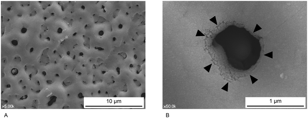 | ||
| Fig. 5 Ion beam deposition is used to apply CaP on the anodized Ti surface (Dentium, Seoul, Korea). (A) In low-magnification SEM images, it is difficult to detect nanotopographical changes caused by CaP. (B) The CaP layer (black arrowheads) can be seen in higher magnification SEM images. | ||
CaP-Coated Ti dental implant surfaces modified at the nanoscale exhibit superior osseointegration and higher bioactivity than uncoated Ti dental implant surfaces.110,111 Ion beam-assisted deposition is another method used to coat implant surfaces with CaP.110,112 The thickness of the coating formed using this approach is around 500 nm.110 Briefly, disc-form evaporants (HA + 37% calcium oxide [CaO]) are sintered inside a vacuum chamber for 2 h at 1000 °C.110 An electron beam is applied to the vacuum chamber, and HA and CaO evaporate and adhere to the implant surface.110,113 When CaP is nanocoated onto implants with different textures in various bony environments, no difference in osseointegration is observed between roughened and smooth surfaces with sufficient bone area, whereas CaP nanocoated onto a roughened Ti dental implant surface increases osseointegration in a bone-deficient environment.110 Ti dental implants with CaP nanocoating on a minimally rough etched surface are commercially available (Nanotite, Biomet 3i, Palm Beach Gardens, FL, USA).
Fluoride (F−) is specifically attractive to Ca and P, the major elements of human bone.114 The surface of grade 4 commercially pure Ti is reduced at the cathode when it is immersed in a dilute solution of HF, which attracts fluoride ions to the implant, and the resultant surface is fluoride-modified.7,115 In the dental implant market, only OsseoSpeed (Astra Tech, Dentsply, Waltham, MA, USA) uses a fluoride-modified surface. To generate these implants, a low concentration of hydrogen fluoride is applied to a Ti surface blasted with TiO2 particles. This cathodic reduction results in fluoride incorporation into TiO2 without a significant change in surface microstructure. In terms of roughness, the Sa of the OsseoSpeed surface is approximately 1.5 μm, making it moderately rough (Fig. 6).117,118 X-ray photoelectron spectroscopy can detect trace amounts of fluoride on the implant surface, but energy-dispersive spectroscopy detects no fluoride content.23,26
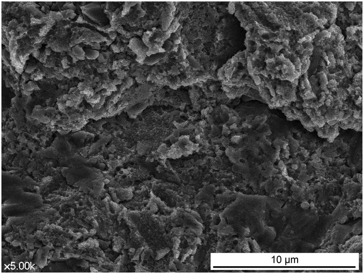 | ||
| Fig. 6 Image of a fluoride-treated surface (Osseospeed, Astra Tech, Dentsply, Waltham, MA, USA). After blasting with Ti dioxide particles, the surface is treated with fluoride. Consequently, the surface is similar to those blasted with Ti dioxide particles alone. | ||
Fluoride acts primarily on osteoprogenitor cells and undifferentiated osteoblasts, but not on differentiated osteoblasts, by increasing growth factor synthesis, facilitating their differentiation into osteoblasts.119 Further, the nucleation capacity of Ca and P ions improves on a fluoride-modified Ti dental implant surface.116 Thus, fluoride may accelerate early bone responses to a modified Ti surface, thereby promoting bone healing. Several in vitro cell studies have demonstrated enhanced expression levels of various osteogenic marker genes on fluoride-modified Ti implant surfaces.116 Moreover, in vivo animal experiments revealed faster bone healing and mineralization on a fluoride-modified implant surface than on a TiO2-blasted surface without fluoride modification.116,120 Clinically, fluoride-modified Ti dental implants are successful in early loading, with 5 or even 10 year survival rates greater than 95%.121–123
Fluoride-modified Ti dental implant surfaces are considered bioactive because, like CaP-coated surfaces, they interact with bone at the BIC more strongly than topographically modified surfaces.20 Fluoride-modified Ti dental implant surfaces likely benefit from the combined effects of modified topography and chemistry. Specifically, such surfaces bind strongly to bone; cutting the interface between the bone and the modified surface is significantly harder than cutting between the bone and the original surface without fluoride treatment.115 Interestingly, the higher quality of newly developed Ti dental implant surfaces is not observed, when compared to other micro-roughened implant surfaces. In vivo studies detected no significant difference in histomorphometry when fluoride-modified surfaces were compared with oxidized or SLA surfaces.26,124 Likewise, one in vivo study reported similar early bone responses between CaP-coated and blasted surfaces.125 Further investigations are needed to explore the effects of these bioactive inorganic elements on bone responses.
Dental implant surface topographies modified at the nanoscale are expected to contribute to accelerating bone responses; however, in contrast with microscale modifications, the benefits and effects of nanomodifications are not yet fully understood at the cellular or tissue levels. In addition, the optimal size and distribution of nanoparticles for application to dental implant surfaces remain unclear. The limitations of the micro- and nano-controls of the surface should also be considered. Even bioactive coatings, such as CaP, have failed disastrously in clinical settings when coated onto the surface of cylindrical Ti dental implants.126,127 After threads were added to dental implants (i.e., conversion of cylinders into screws in terms of macroscale geometry), the same bioactive coating became successful in long-term clinical use.128–130
Functionalized dental implant surfaces coated with arginylglycylaspartic acid (RGD) peptides exhibit superior histomorphometric results, indicating accelerated osteogenesis relative to uncoated surfaces.134 Recently, two functional peptides involved in cell adhesion have been identified in human laminin:30,59 DLTIDDSYWYRI (12 amino acids) and PPFEGCIWN (nine amino acids). These two peptides also actively bind to osteogenic cells, and a mechanism by which they can trigger intracellular cascades has been proposed (Fig. 7).30 Such laminin-derived functional peptides appear to overwhelm the topography and chemistry of the underlying dental implant surface during bone cell attachment, although both the implant surface structure and coating organic compounds affect cellular and tissue responses.59 A functional peptide derived from another adhesion protein, vitronectin, also has strong potential to accelerate bone healing at the bone–implant interface.38,131
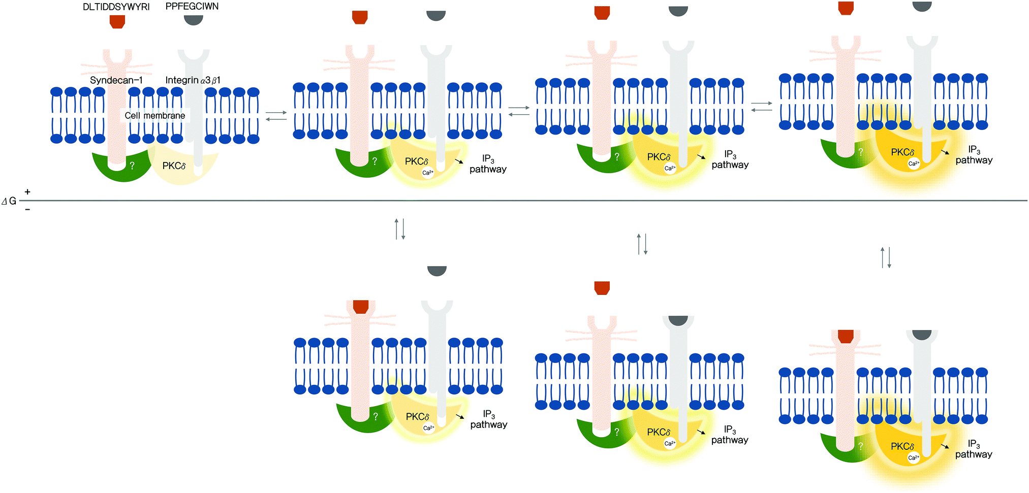 | ||
| Fig. 7 Proposed mechanism, based on a probabilistic interpretation of allostery for two laminin-derived bioactive peptides.14,30 (Reproduced from ref. 14 and 30 with permission from Elsevier.) The black horizontal line indicates that the Gibbs free conformational energy difference (ΔG) is zero. A more stable energy state is shown below the line. The degree of enzyme activation is demonstrated through the brightness and intensity (red lines) of protein kinase Cδ (PKCδ). When functional peptides bind to transmembrane proteins with tunable sensitivity for PKCδ phosphorylation, various conformational energy states are adopted. Even if the peptides do not bind to their receptors, PKCδ can be reversibly activated. Thus, when neither of the peptides binds to the transmembrane receptors, an equilibrium is reached between the inactive (far left) and active states; however, such activated states are likely short-lived due to their high free energy. Circumstances differ when either PPFEGCIWN or DLTIDDSYWYRI, or both peptides bind to the receptors. Binding significantly stabilizes the conformations, increasing the probability of the active states. An increase in the number of active states effectively triggers intracellular events via the transmembrane proteins, promoting cell adhesion. Glow of PKCδ represents the extent of activation (more active to the right). IP3, inositol triphosphate; Ca2+, calcium ions; (?), unknown protein. | ||
Other biomolecules that can enhance bone healing include cytokines, particularly growth factors.7,25 Further, BMPs are candidates for use in clinical dental implantology. BMPs are temporal signaling molecules with complex biological effects that depend on their concentrations and the conditions of surrounding tissues. Human recombinant BMP-2 (rhBMP-2) is currently used in the clinic, and rhBMP-2-coated Ti dental implants accelerate bone healing in vivo;135,136 however, cytokines are not adhesion molecules, and BMPs are ineffective when coated onto surfaces because their bone-healing effect requires free diffusion in the tissue microenvironment.116 A previous study reported that BMP-2 applied directly to osteoblastic cells promotes cellular adhesion to Ti dental implant surfaces by increasing adhesion molecule expression.137 Some studies have reported conflicting results concerning BMP-2, including osteolysis or negative effects on osteogenesis around BMP-2-treated implants.138–140 Moreover, it is difficult to directly coat BMP-2 on to Ti. Some studies used BMP-2 in free form, whereas others coated BMP-2 on a surface modified by application of CaP, other growth factors or the anodic oxidation technique, and the effects on bone responses were mixed.110,135,136,141,142
To establish a more biomimetic environment at the bone-healing site, a growth factor can be combined with dental implant surfaces coated with an adhesion molecule. One study proposed that adhesion molecules can exert bone-induction effects in the presence of BMPs.143 Dental implant surfaces functionalized with adhesion molecules and nanocarriers are also applicable; in this setup, nanocarriers contain growth factors and release them in free form after implant insertion. The initial bone response and subsequent bone remodeling can be manipulated by controlling the time of release of the contained factors. The peptide-functionalized implant surface is predicted to control the biological environment, which leads to implants that are more readily available for edentulous patients with some metabolic disorders; for example, a Ti implant treated with a vitronectin-derived peptide stimulates osteoblast activity and inhibits osteoclast activity, making it a candidate device for osteoporotic patients.131
This section has focused mainly on modified implant surfaces successfully used in clinics; however, implants more readily applied in patients with certain metabolic diseases and peptide-treated implant surfaces warrant consideration for future use, although these surfaces have yet to be employed in the clinic.
Immobilizing peptide molecules on an implant surface is another major challenge. Physical adsorption is the simplest and easiest method for immobilization, where peptides are non-covalently applied on the surface;144 this is the main methodology employed in many previous studies and is effective for maintaining molecular activity, due to low dependence on peptide conformations, which are critical in determining the activities of the original proteins;30,38–40,131,144,145 however, this immobilization strategy poses difficulty in delivering sufficient peptide molecules to target sites.144 Conversely, covalent immobilization methods are resistant to the damage associated with peptide layers applied during dental implant installation, whereas process complexity related to covalent bonding, purification, detoxification and monitoring, and additional costs are obstacles to the transition from laboratory to manufacturing scales.144 If peptide-functionalized implants are clearly shown to display stronger osseointegration in edentulous patients with bone metabolic disease, new or established immobilization techniques may be applied to manufacture dental implants.
3. The gingiva–abutment interface (soft tissue seal)
3.1. The soft tissue seal
The tooth penetrates the gingiva to connect external and internal environments. The root of the tooth is fixed in alveolar bone, and the transition region contacts epithelial and connective mucosal tissue. The hole (or flaw) formed by a tooth is sealed by a special structure consisting of epithelial tissue and connective attachment in the transition region. The epithelial tissue is attached to teeth by the internal basal lamina and hemi-desmosome, and the connective tissue adheres through a combination of dento-gingival fibers and cementum.146 Thus, the soft tissue attachment seals the flaw, and the tooth generates the hole connecting the external and internal environments. In a dental implant, the soft tissue attachment is similar, but not identical to that of natural teeth (Fig. 8A).147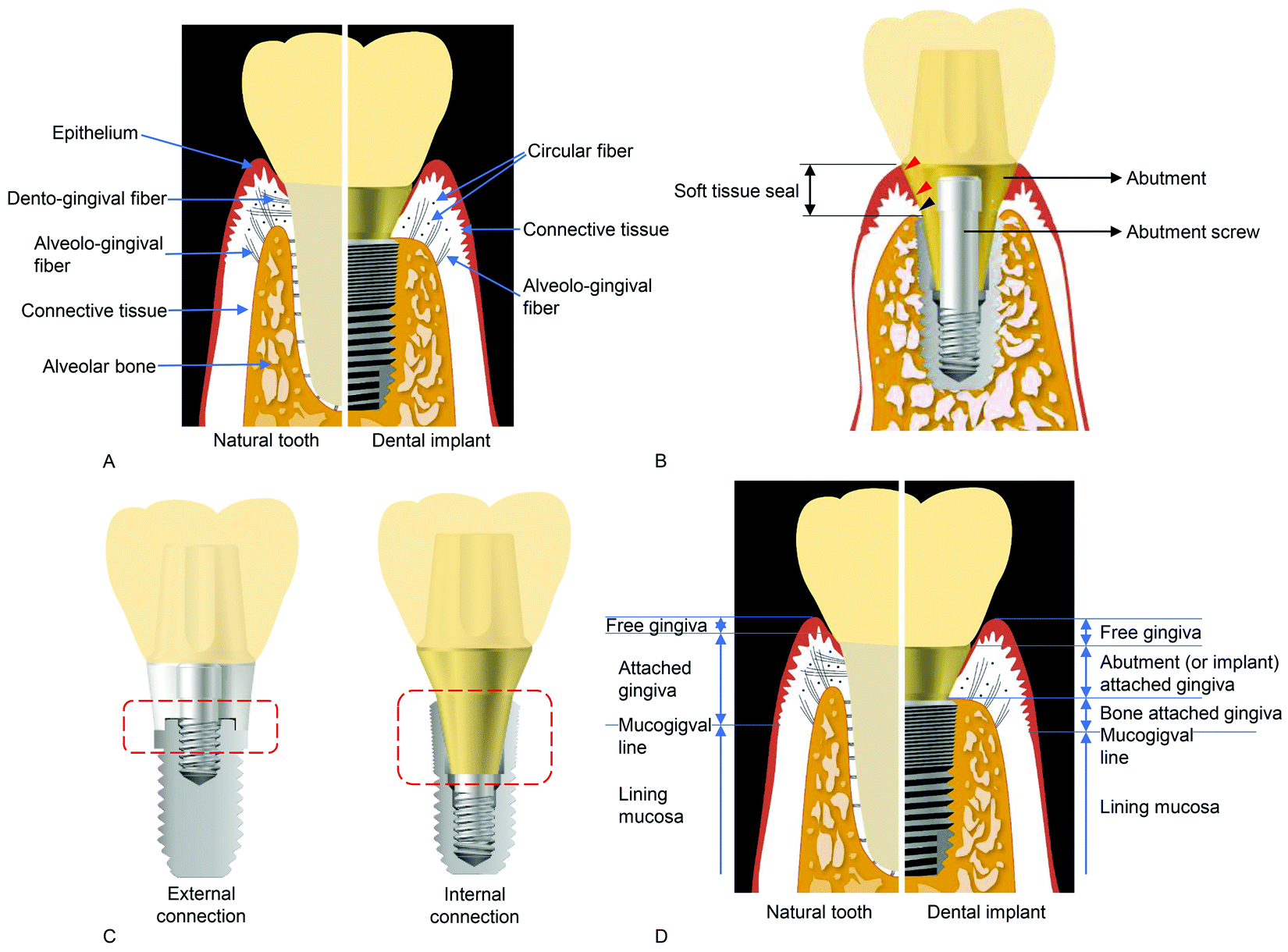 | ||
| Fig. 8 (A) Soft tissue and collagen fibers around a natural tooth (left) and a dental implant (right).5 (Reproduced from ref. 5 with permission from Multidisciplinary Digital Publishing Institute.) Note that there are no dento-gingival fibers surrounding the implant. (B) Soft tissue seal and abutment screw (cross-section of an implant-supported restoration). An abutment screw clamps the abutment and implant, and the stability of the connection determines the stability of the soft tissue seal, consisting of epithelial (red arrowheads) and connective tissue (blue arrowhead) attachments. (C) A typical example of an external connection (left) and an internal connection (right). Dashed red boxes show the difference in mating surfaces between the two connections: a butt-joint, or an abutment placed on the implant platform, is shown in the external connection, while friction occurs between the inclined planes of the implant and abutment, contributing to abutment stability. (D) Schematic diagram of the soft tissue structures around a natural tooth (left) and a dental implant (right). Note the gingiva directly attached to the surfaces of implant parts, indicating that the sealing capability of this structure is lower than that surrounding the natural tooth.5 (Reproduced from ref. 5 with permission from Multidisciplinary Digital Publishing Institute.) | ||
A dental implant is anchored to alveolar bone and the abutment contacts the soft tissue (epithelial and connective tissue) in the transition region. The connective tissue attachment to the abutment of a dental implant does not involve dento-gingival fibers, which adhere perpendicularly to cementum in natural teeth. The collagen fibers around the abutment mainly run parallel and circularly to the surface. The connective tissue attachment around the abutment is maintained by the elasticity of circular fibers and fibroblasts holding the collagen fibers, unlike the natural teeth, where the fibers are directly inserted (Fig. 8A).148 Therefore, the connective tissue attachment around the abutment must be weaker than its counterpart in natural teeth. The epithelial attachment around the abutment is also weaker than that in natural teeth, due to the restricted distribution area of the internal basal lamina and hemidesmosomes.149–155 Thus, the soft tissue attachment (epithelial and connective tissue attachment) sealing the hole (or flaw) is weaker around implants than that in natural teeth.
The soft tissue seal, or mucosal seal, is another important factor determining long-term implant success.5,156,157 The soft tissue seal around a dental implant is defined as the attachment of epithelial and connective tissues to the surfaces of the implant system, mainly the abutment surface.5 It is necessary to understand both the abutment surface directly attached to soft tissue and the mechanics of abutment-to-implant connection via an abutment screw, because the unstable state of the connection from the mobile abutment leads to breakage of the soft tissue seal (Fig. 8B and C).48,158
In dental implantology, an implant and an abutment are connected through a unique mating structure. When an abutment connects to the ‘outer’ structure of an implant, it is referred to as the ‘external’ connection, while abutments connected to the ‘inner’ structure of an implant are called ‘internal’ connections (Fig. 8C). Originally, implant–abutment connection stability was accomplished using an abutment screw alone;6 however, due to mechanical complications associated with the screw, a more stable connection has been achieved using a specific mating structure between the implant and the abutment, to minimize the role of the abutment screw.5,159 The most important feature, for both external and internal forms, is whether movement is allowed between an abutment and the connection structure. Most biological and mechanical complications of dental implant systems are related to the mobility of implant-to-abutment connection.160
3.2. Importance of the soft tissue seal
The complete immobility of the soft tissue contact to the abutment is important for the long-term predictability of implants.5 If peri-implant soft tissue is mobile, the attachment will be severed because the structure is weaker than that in natural teeth, resulting in disruption of the soft tissue seal.5,148,156 Bacteria can invade through the damaged mucosal seal, resulting in peri-implant disease or inflammation.156,157 Therefore, the soft tissue seal is the most important factor in preventing peri-implant disease because it protects against bacterial invasion.157,161The mucosa around natural teeth is classified as either masticatory or lining mucosa, where masticatory mucosa consists of free gingiva and attached gingiva (Fig. 8D). Attached gingiva is responsible for soft tissue immobility by tightly attaching to the surface of enamel, cementum, and alveolar bone.146 Thus, immobility contributes to preserving a firm and healthy soft tissue seal. The components of soft tissue around implants are essentially similar to those surrounding natural teeth; however, the attached gingiva around implants differs.147 Attached gingiva around implants is either bone-attached or abutment (implant)-attached (Fig. 8D). Bone-attached gingiva is the same as that of natural teeth, and provides solid immobility, whereas abutment-attached gingiva is weaker, and approximately equal in strength to free gingiva.147 Therefore, if bone-attached gingiva is of insufficient width to prevent mucosal mobility, peri-implant disease becomes more likely, due to the fragile structure of abutment-attached gingiva.147,162
Second, unstable implant–abutment connection can also disrupt the soft tissue seal.5,158 Dental implant systems comprise three parts: a prosthetic (artificial crown), a transition (abutment), and an implant. Transition part mobility can cause destruction of the mucosal seal. A mobile implant can lead to failed osseointegration, while a mobile abutment implies the mobility of the transition part, regardless of successful osseointegration. Abutment mobility is mainly caused by loosening of the abutment screw that stabilizes the implant–abutment assembly.163 Loosening is more frequent in external than internal type implants, due to elongation and unscrewing of the abutment screw following lateral occlusal force.164,165 Due to friction between the inclined planes of an implant and abutment, lateral occlusal force is concentrated in this type of internal connection, not on the abutment screw but on the implant wall through the abutment–implant connection area.159,166 Therefore, screw loosening is less frequent in such internal type connections.167 A wider abutment can avoid stress concentration on specific sites, including the abutment screw, and contribute more to soft tissue seal stability than a narrow connection. The soft tissue around implants can be maintained by support from healthy sub-alveolar bone, which should be stimulated appropriately to preserve healthy dynamic conditions.16 The appropriate stimulation and distribution of strain can be achieved in wide and deep connections between these two parts (abutment and implant).166
(1) Healthy peri-implant shows neither bleeding on probing nor inflammation, with normal or reduced bone support. Peri-implant problems are not found in measured probing depth data.169–171
(2) In peri-implant mucositis, bleeding on probing and inflammation can be observed by visual inspection; peri-implant mucositis is mainly plaque-induced.172
(3) In peri-implantitis, bleeding on probing, inflammation around peri-implant mucosa, and progressive loss of supporting bone are observed. This is a plaque-associated pathological condition of soft tissue around dental implants. Poor plaque control and a history of severe periodontitis both contribute to peri-implantitis.173
In practice, transition into peri-implant disease is caused by disruption of the mucosal seal, enabling bacterial invasion, but not by the bacterial plaque itself, although treatment of peri-mucositis and peri-implantitis can eliminate plaques.168 Therefore, maintenance of a healthy mucosal seal, including by use of micro- and nanotechnologies to strengthen this soft tissue attachment, is much more significant than plaque control or antibacterial biomedical technology regimens. Immobile soft tissue and implant–abutment connection are important, since the mucosal seal around implants is weaker than that around natural teeth. Free gingiva and abutment (or implant)-attached gingiva are unable to provide immobility, unlike bone-attached gingiva and rigid connection between an implant and abutment.174 Immobility contributes to maintain a healthy mucosal seal, protect against bacterial invasion, and thereby prevent transition into peri-implant disease.
3.3. Importance of abutments in the soft tissue seal
In general, an implant abutment is divided into three parts regardless of its mating type with reference to an implant; each part is determined by what is attached to it (Fig. 9A).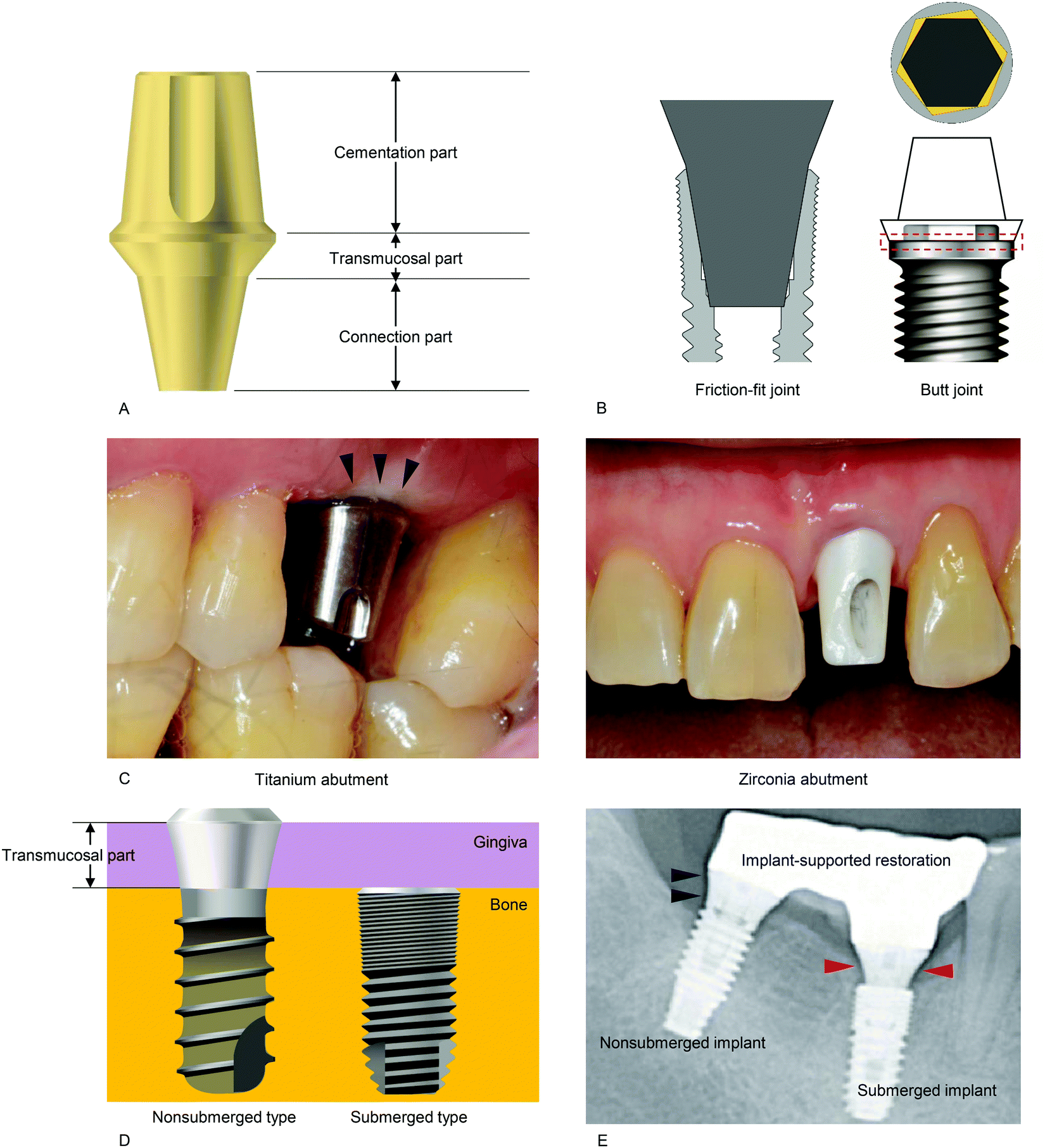 | ||
| Fig. 9 (A) Three structures of an abutment, showing cementation, transmucosal, and connection areas. An artificial crown is cemented to the cementation part. The soft tissue seal is formed at the transmucosal area. The connection surface interfaces the surface of an implant (here, the inner surface). (B) Friction-fit joint (left) and butt joint (right). The top view shows the red dashed rectangular area in the diagram above, while the yellow area shows the machining tolerance allowing the possible movement of the abutment. (C) Titanium (left) versus zirconia (right) abutments. Note that the metal shade of titanium is reflected through the gingiva (black arrowheads). (D) Schematic diagram of a nonsubmerged implant (left) and a submerged implant (right). In the nonsubmerged implant, the transmucosal part forms an interface with the gingiva. (E) X-ray image showing the transmucosal collar (black arrowheads) around the implant in a nonsubmerged implant system, whereas the abutment (red arrowheads), rather than the implant, has a transmucosal layer in a submerged system. | ||
(1) The cementation part is a cylindrical structure connected to a prosthesis (artificial crown). This part is related to retention of the prosthesis, based on its resistance to disconnecting force. Retention is enhanced by increased height and narrower diameter.
(2) The transmucosal part is the surface where the soft tissue seal forms. This part is particularly important because oral bacterial penetration can occur where a dental implant pierces the oral mucosa. Therefore, the soft tissue seal in this region must be healthy and undisturbed to ensure implant longevity.
(3) The connection part is an interface where an abutment and an implant contact directly. This part is especially important in determining the longevity of an implant because it can transfer an occlusal load from a prosthesis to an osseointegrated bone.
As mentioned earlier, abutments and implants are strongly connected by abutment screws. Usually, a torque of 25 to 35 Ncm is applied to the screw for preload.163 If the preload decreases for any reason, the connection between an abutment and an implant is loosened, the soft tissue seal is broken, and this can lead to peri-implant disease.5,48,158,163 The use of an implant system with a mechanism by which stress is not concentrated on an abutment screw is therefore useful for the long-term clinical service of an implant.48,158
In a butt joint, two right-angled flat surfaces mate, leaving a small space between the mating parts. By contrast, a friction-fit joint leaves no space between the mating parts, since the parts are forced together. The Brånemark implant, the first commercialized screw-shaped endosseous dental implant, has an external and hexagon-mediated butt joint connection, and similar types of implants have been manufactured and sold in the dental market worldwide.176–178 The space in this joint type can cause movement of an abutment when occlusal load is applied. At one time, a microgap (a small gap formed between an abutment and an implant) was thought to cause marginal bone resorption by acting as a habitat for bacteria, thereby triggering marginal bone loss.179–181 Based on this assumption, marginal bone resorption was considered an inevitable physiological phenomenon. More recently, Hermann et al. showed that marginal bone resorption resulted from abutment movement, not microgaps.182 Thus, overall, evidence suggests that abutment movement can break the soft tissue seal around an abutment, potentially resulting in marginal bone resorption.48,158 The friction-fit type can limit the movement of an abutment by friction generated at the interface, which may enhance the stability of the soft tissue seal, and prevent marginal bone resorption.5,48,156,183,184
Polyetheretherketone (PEEK) has been suggested as a material for abutments. This resin polymer is advantageous in chairside customization and gingival aesthetics, compared to metal abutments.161 A previous animal experiment showed soft tissue quality around PEEK abutments similar to that around Ti.188 Similar soft and hard tissue responses were also found in a previous randomized controlled trial comparing PEEK abutments with Ti.189 However, such a polymer abutment is provisional, which is used as a healing abutment for a short period.161,190
Nowadays, the main materials used for abutments are Ti and zirconia (Fig. 9C). Traditionally, only Ti was used, but zirconia was developed for esthetic reasons due to the metallic color of Ti. A recent systematic review concluded that zirconia abutments are more advantageous as they cause less discoloration of the soft tissue than Ti abutments.191 In addition, a previous meta-analytic study described that zirconia abutments showed less bacterial adhesion, less plaque retention and less soft tissue inflammation than Ti.192 In terms of the soft tissue seal, however, there is abundant evidence that there are no significant differences between the two materials;186,187,193 furthermore, zirconia has a lower fracture strength than Ti, and hence, Ti is still widely used in abutments. If a zirconia abutment is used, the high fracture rate can disrupt the soft tissue seal. Clinically, it is possible to overcome the esthetic problem of the color of Ti with a bone graft, a soft tissue graft, and modification of the prosthesis. A recent meta-analysis of spectrophotometric evaluation has revealed that there was no clear evidence supporting the superiority of zirconia abutments in peri-implant soft tissue color, compared to Ti abutments.194
Some animal studies revealed higher attachment of connective tissue on a laser-grooved Ti abutment, when compared to the turned smooth-surfaced Ti abutment.203–205 The connective tissue fibers were perpendicularly oriented to this laser-treated abutment, which is more protective against bacterial invasion.206 A Ti abutment treated by oxidation also showed the improved soft tissue seal in another previous animal study, when compared to the turned smooth-surfaced Ti abutment.207 Thus, in terms of surface roughness, the soft tissue seal may be improved when the abutment surface is rougher, although some studies are found to fail in detecting significant differences between modified rough and turned smooth abutment surfaces in soft tissue attachment.208,209 This is because rougher surfaces provide a greater available surface area for soft tissue to attach.210
Nanotechnologically, photofunctionalization by ultraviolet rays, coating cell adhesive molecules including poly-L-lysine and nanoporous modification of abutment surfaces were also reported to strengthen the soft tissue seal around the abutments.201,202,211 In one in vitro study, Yang et al. showed that gingival fibroblasts proliferate more strongly on smooth or rough zirconia surfaces following ultraviolet irradiation.212 Epithelial attachment was also improved on both the abutment surfaces with poly-L-lysine coating and with laser-induced micro- or nano-pores that were within 5 μm in diameter.201,202
Abutment surface modification can improve the soft tissue seal. However, more plaque may accumulate on treated surfaces when the seal is broken. Modification of the abutment surface usually changes the surface roughness or surface free energy, which may increase the probability of bacterial colonization.213–215 Furthermore, an unstable implant–abutment connection can make a modified abutment surface ineffective in the tight seal of soft tissue because such an instability allows abutment movement during mastication.5,182 Clinical investigations are lacking and are needed to verify the effect of abutment surface treatment on the soft tissue seal, which safe-guards the implant from bacterial invasion and peri-implantitis.202
Histologically, there are no significant differences between nonsubmerged and submerged implants; the type and extent of soft tissue attachment are similar.220 The amount of soft tissue seal is 3 to 4 mm in an implant site; hence, the height of this part should be at least 3 mm.221 When the height is less than 3 mm, which often occurs on deep insertion of a nonsubmerged implant, marginal bone resorption can occur to accomplish 3 mm of soft tissue seal.219 The transmucosal collar of a nonsubmerged implant is usually machined to be smooth. Recently, there have been many attempts to reinforce the soft tissue attachment, such as by roughening the transmucosal area, or adding microgrooves to the transmucosal surface by laser treatment.203,210,215,222–225 Connective tissue fibers are reported to perpendicularly adhere to microgrooved surfaces, which are more resistant to inflammatory infiltration;226 however, these modifications increase biofilm formation on the surface, resulting in a more inflammatory environment around the implants.215,222
4. The implant–abutment interface: mechanical properties provoking pathogenesis
The success of dental implant treatment depends on many factors affecting the implant–abutment interface as well as the implant–bone and abutment–soft tissue interfaces.158,159,175 One of the most frequent complications in the field of clinical implantology is loosening of the abutment screw between an implant and abutment, which may result in peri-implantitis.177,227 This complication can lead to implant failure. Therefore, it is necessary to understand the implant–abutment interface, consisting of an implant, abutment, and abutment screw.4.1. Biomechanics at the implant–abutment interface
In general, stability of the implant–abutment connection is essential for the long-term clinical success of a dental implant.5,48,158 To effectively tackle complications arising from unstable implant–abutment connection, which can occur on a daily basis, we must comprehend the biomechanics at the implant–abutment interface. Herein, we discuss the biomechanics of the two implant–abutment connections most widely used in the global dental implant industry: screw-retained only (SR) and friction-screw-retained (FSR).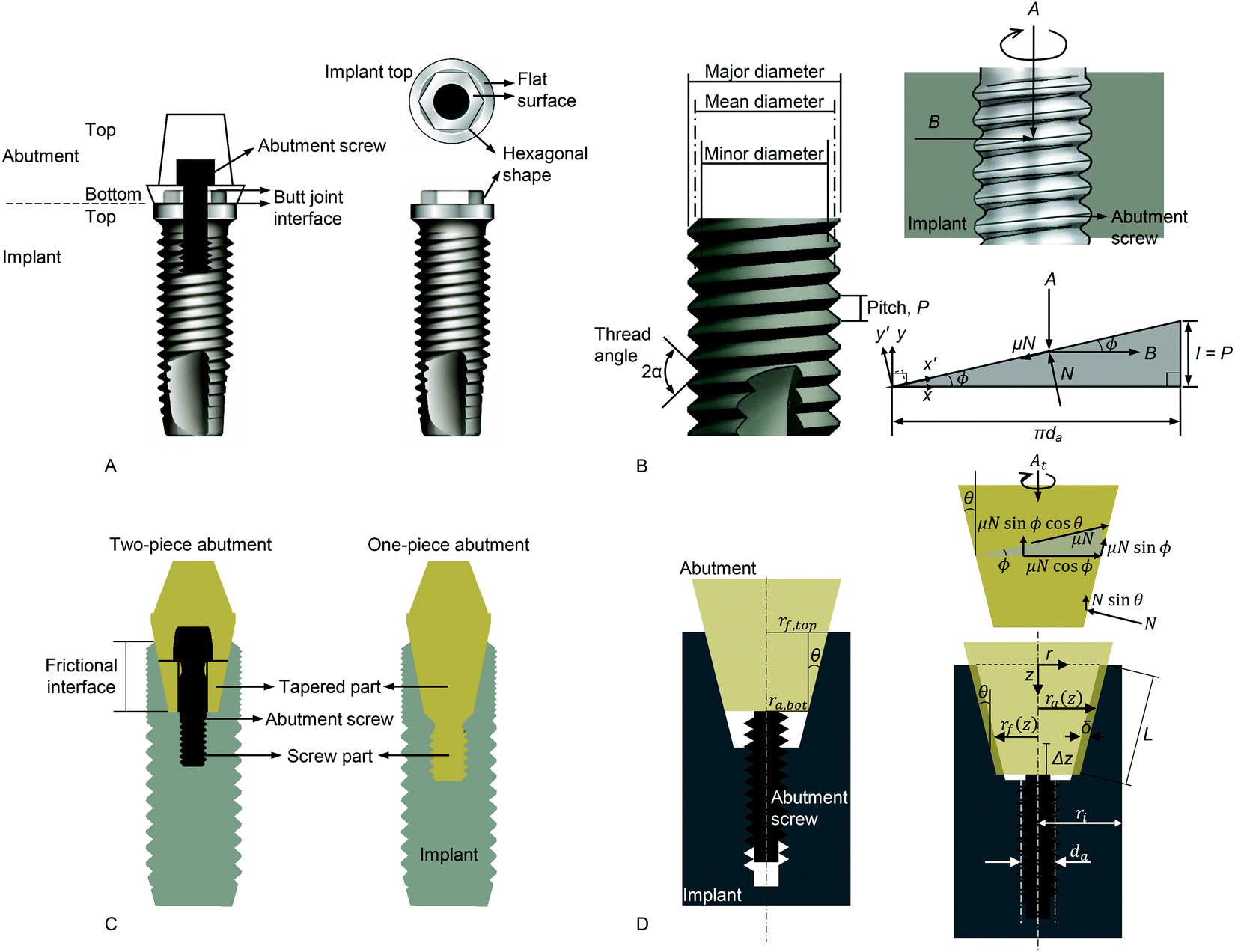 | ||
| Fig. 10 (A) The SR connection structure in dental implants. This diagram shows why the connection is called an external hex connection in clinical dentistry. The abutment covers the hexagonal part of the implant top area. Notably, the butt joint is made between the flat surfaces of the implant and abutment. (B) Terms and diagrams for screw mechanics. The major diameter is defined as the largest diameter of a screw thread, and the minor diameter is the smallest diameter. The mean diameter is the average diameter of a screw, which is, strictly, not the mean of the major and minor diameters. When the abutment screw is tightened, a preload, A, is generated. All screws in this section are right-handed. A free body diagram, or force analysis, is shown in the lower right corner. (C) The FSR connection structure in dental implants. A two-piece (left) and one-piece (right) abutment are shown. Note that the tapered and screw parts are fused into a single body in the one-piece abutment, which implies that a decrease in preload in the screw part would have a stronger effect on the tapered part, compared with a two-piece abutment. (D) Diagrams depicting friction mechanics in the FSR connection.159 (Reproduced from ref. 159 with permission from Elsevier.) On the left, the abutment is placed in the implant with no interference. Tightening causes the abutment to engage tightly into the implant with interference (δ), shown on the lower right. Friction and preload occur between the interfaces, and contribute to the stability of the FSR implant–abutment connection. The free body diagram (upper right) is shown at the tapered or conical area. | ||
Some of the terms used in screw mechanics are illustrated in Fig. 10B. All screw components of implant systems discussed here have single threads (i.e., the lead, l, of the screw is the same as its pitch, P). The biomechanics of the SR connection can be theoretically analyzed using screw mechanics with a free body diagram (Fig. 10B). Acceleration is zero when torque is applied to a screw just before it rotates. The equilibrium of force for the horizontal axis (FH) is expressed using the following equation:163
FH = −Asinϕ + B![[thin space (1/6-em)]](https://www.rsc.org/images/entities/i_char_2009.gif) cosϕ − μN = 0 cosϕ − μN = 0 | (1) |
| N = Acosϕ + Bsinϕ | (2) |
| Bcosϕ − Asinϕ = μ(Acosϕ + Bsinϕ) | (3) |
 | (4) |
 is the mean screw diameter.163 For a typical ‘V-shaped’ thread with a thread angle 2α, the frictional terms in eqn (4) must be divided by cosα.229 Therefore, if
 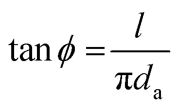 is applied to eqn (4), eqn (5) becomes
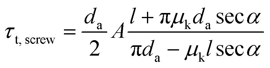 | (5) |
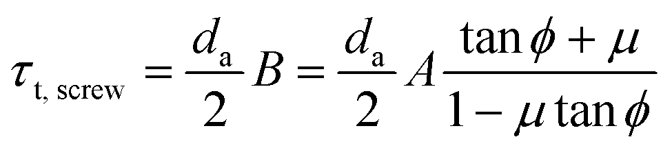
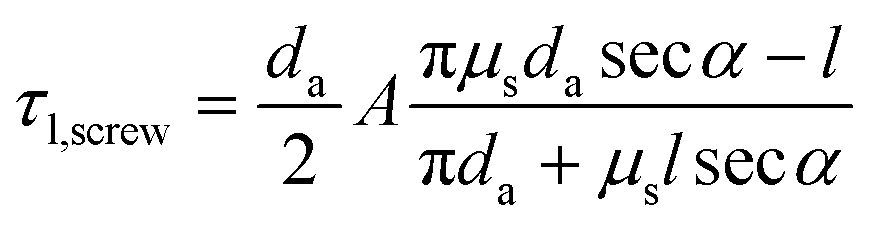 | (6) |
The difference in torque between tightening and loosening is linearly calculated from a simple equation, since ϕ and μsecα are very small values.163
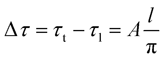 | (7) |
This analytical approach indicates that the torque clinically recommended by the manufacturers, of 30–35 N cm, was actually insufficient to prevent screw loosening events. In clinical terms, this indicates that abutment screws should be repeatedly retightened in the SR connection for butt-joint interfaces between abutments and implants. Another important point raised by these studies is that features other than screws are needed to continuously maintain the implant–abutment connection. An interface stabilized by friction is one option, and is described below.
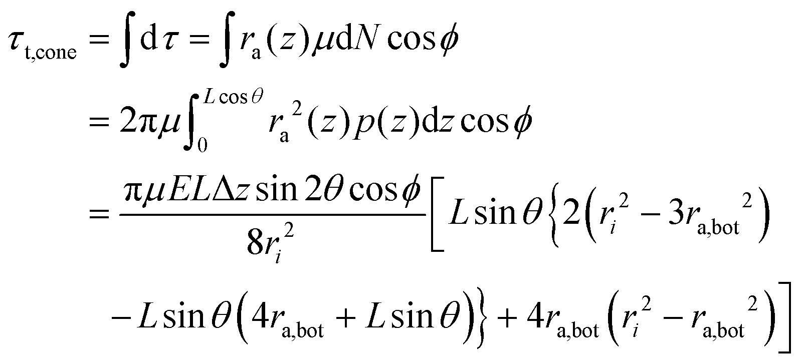
When the implant and the abutment are made of the same material, the biomechanics of the FSR connection between the conical (tapered) and screw parts are analyzed separately.159 The total tightening torque, τt,total, is the sum of the torque values of the conical and screw parts:
| τt,total = τt,cone + τt,screw | (8) |
θ when the abutment is placed in the implant with no interference. The tightening procedure induces a vertical force and the abutment tightly engages into the implant with interference, as shown in Fig. 10D (right). Interference, δ, and contact length, L, are calculated as follows:228| δ = Δztanθ | (9) |
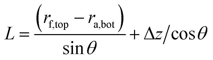 | (10) |
 | (11) |
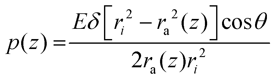
| ra(z) = ra,bot + (Lcosθ − z)tanθ | (12) |
| rf(z) = rf,top − ztanθ | (13) |
| dN = p(z) × 2πra(z)dz | (14) |
 | (15) |
The total tightening torque, τt,total, is obtained by combining eqn (5), (8), and (15)
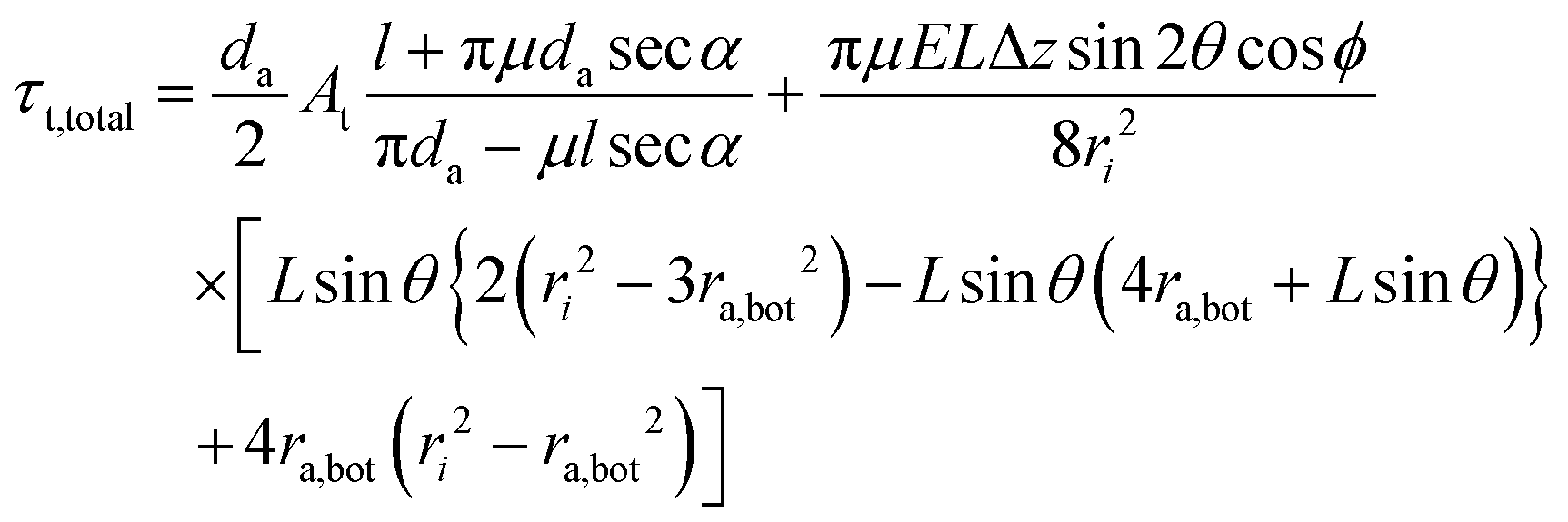 | (16) |
sinθ + μNsinϕcosθ (Fig. 10D).159
Total loosening torque can also be analyzed in the same way. The preload becomes Al = Nsinθ − μNsinϕcosθ at loosening, because the vector of friction is opposite to the direction at tightening. The loosening torque, τl,cone, gives the same result at the conical part from eqn (14):159
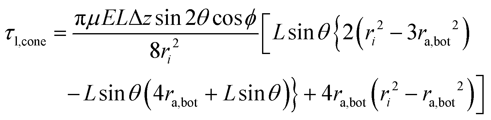 | (17) |
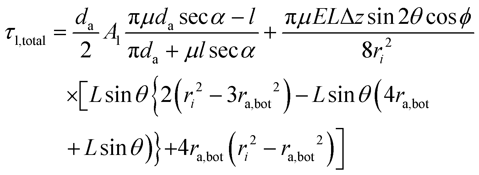 | (18) |
Eqn (16) and (18) predict various biomechanical properties for FSR connections. Notably, the magnitudes of both torques depend on the contact length, L, in a four-powered manner (i.e., L4). A slight increase in contact length results in a huge increase in loosening torque, clearly stabilizing the implant–abutment connection. When an implant and abutment are made of grade 4 commercially pure Ti, using the other parameters of the FSR connection listed in Table 1, a graph of the loosening torque versus the contact length can be plotted (Fig. 11).
| a Parameters are not exact values, they are taken from the literature.159,163,228 | |
|---|---|
| Taper angle (θ) | 11° |
| Frictional coefficient (μ, μs = μk) | 0.3 |
| Contact length (L) | 2.228 mm |
| Half of the major diameter of the fixture (ri) | 2.205 mm |
| Δz | 5 μm |
| Bottom radius of the abutment (ra,bot) | 1.427 mm |
| Young's modulus (grade 4 Ti) | 113.8 GPa |
| Mean diameter of the abutment screw (da) | 1.74 mm |
| Lead length of the abutment screw (l) | 0.4 mm |
| Lead angle of the abutment screw (ϕ) | 4.19° |
| Thread angle (2α) | 60° |
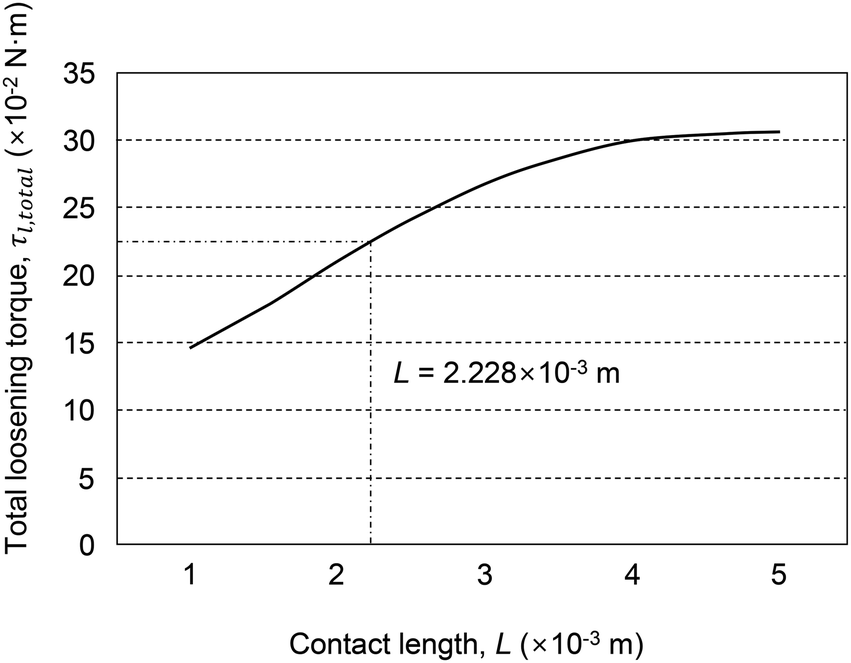 | ||
| Fig. 11 The effect of contact length, L, on the total loosening torque, τl,total. This graph shows total loosening torque values, based on the data in Table 1. | ||
When the contribution quotient of the FSR connection is defined as the ratio of torque at the conical part to the total torque, the quotient is >0.8, which implies that the conical part of the FSR connection is a major contributor to implant–abutment connection stability.159 Regarding the loosening procedure, the screw part is unable to stabilize the FSR connection after the onset of loosening, because the screw preload vanishes. Therefore, the contribution quotient is 1; only the conical part contributes to the FSR connection.159 This frictional tapered part acts as an alternative stabilizer for implant–abutment connection when the preload of the screw part diminishes, especially for 2-piece abutments.
From eqn (16) and (18), loosening torque is linearly proportional to tightening torque. Subsequently, the screw preload is linearly proportional to tightening torque. These linear relations are discussed above, and have been demonstrated both theoretically and experimentally.163 Importantly, torque, preload, and implant–abutment stability are strongly affected by the interfacial frictional coefficient. Roughening or smoothening technologies at micro- or nano-scale to control the frictional coefficient can be crucial for implant–abutment stability, which is a key factor for biological and inflammatory responses around dental implants.
4.2. Control of the implant–abutment interface
To ensure the longevity of implant restorations, dental clinicians should seek to avoid any problems with the abutment, abutment screw, and prosthesis, by considering both mechanical and biological aspects of implant restoration. Mechanical complications include fracture or tearing of implants, fracture or loosening of an abutment screw, and fracture or dislodgement of a prosthesis (Fig. 12A).232 Biological complications include problems in the osseointegrated bone and peri-implant mucosa, resulting from bacterial invasion (Fig. 12B).232 Biological complications are divided into peri-implant mucositis and peri-implantitis, the equivalent of gingivitis and periodontitis, respectively, in natural teeth.168 The onset and progression of peri-implant disease and periodontal disease are similar, indicating comparable bacterial composition.233 Biological complications caused by bacteria and mechanical complications were previously considered independent, but recent studies have demonstrated that they are associated.234–236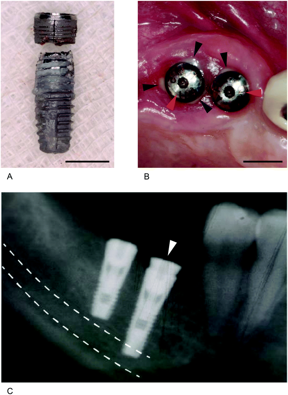 | ||
| Fig. 12 Mechanical and biological complications of dental implants. (A) A fractured implant removed from the mouth of a patient. (B) Discharged yellowish pus (black arrowheads) found around the healing abutments (red arrowheads) connected to dental implants placed into the bone. (C) A long implant (white arrowhead) placed in the right mandibular first molar area invading the anatomical structure (the inferior alveolar canal; white dashed line), where the inferior alveolar nerve is located. Scale bars = 5 mm. | ||
Disruption of the soft tissue seal is the main cause of peri-implant disease; detachment of the soft tissue seal allows colonization and invasion of bacteria, eventually leading to the peri-implant disease.5 Destruction of the soft tissue seal around an implant can be driven by a lack of attached gingiva, shallowness of the vestibule, or a high frenum, but mainly results from movement of an abutment, due to a non-rigid and unstable connection between implant and abutment.5,48,156 Therefore, mechanical joint stability between implant and abutment is a major factor determining the longevity of implant restorations.48,158 There are several factors that contribute to a stable connection between implant and abutment.48,158,159,163
After delivery of a prosthesis, three kinds of force are applied to the implant-to-abutment interface: vertical, lateral, and rotational.5 Physically, rotational force is a type of lateral or horizontal force. Most implant systems struggle with lateral force, but not vertical force, because the mating structures of the implant and abutment can tolerate vertical force.5 Conversely, lateral force can loosen the abutment screw, making the abutment mobile. Essentially, the hexagonal male and female structures in each connecting part of an implant and an abutment are engineered to tolerate rotational force.237 Therefore, in general, vertical, lateral, and rotational forces are supported by an implant–abutment mating structure, an abutment screw, and a hex structure.5,238 For long-term successful results, an implant–abutment mating structure should endure and distribute these forces.48,166,238
The Brånemark implant system (Nobel Biocare, Zürich, Switzerland), the first marketed screw-shaped implant, is an example of an SR connection. In this system, the vertical force is endured by the platform of an implant and the mating abutment, while the lateral force is endured by the hex device and abutment screw, and the rotational force by the hex device.238 This SR connection is a mobile structure, and occlusal forces are concentrated on an abutment screw.237,238 Therefore, bacterial penetration is common, and peri-implant disease is likely to occur. To prevent movement of the abutment in this connection, the external hex feature should be lengthened, and the machining tolerance between female and male hex parts made more intimate. Alternatively, an abutment screw made from stronger materials can be incorporated, and the implant platform widened, to minimize the forces focused on the abutment screw. In addition, when a stronger tightening torque is applied, the strength of the connection is enhanced;163 however, it is impossible to completely prevent movement of the abutment in this type of joint, because the external hex structures of the implants used clinically are approximately 0.7 mm in height, and therefore unable to maintain implant–abutment connection stability under the stress of daily mastication (occlusal force).5,237
Many commercially popular implants have FSR connections, which also have an abutment screw, but this is less important than the butt joint in terms of stability.159,166 Additionally, a few manufacturers produce implants without an abutment screw, in which the implant and abutment are held only through high friction between the two parts.228,239 These joints have a 1.5° taper angle between the implant and abutment connection on one side, which locks the abutment and implant tightly, without an abutment screw.239 This tight connection can bear vertical, horizontal, and rotational forces, rendering the abutment immobile, and thereby avoiding soft tissue seal disruption.237 Therefore, marginal bone resorption rarely occurs with this system.5,48,240 The degree of tapering of the abutment to the implant interface is a crucial factor in determining abutment mobility in the FSR connection; the wider the angle, the more unstable the abutment to implant connection, and the greater the need for an abutment screw.159
When an implant meets an abutment via the FSR connection, there is an intimate contact between them, initially at the connection surface, subsequently at the base, and then over the entire surface. This is because the implant top is gradually opened, causing the abutment to sink down, which loosens the abutment screw, leading to a need for periodic re-tightening.175,241,242 Otherwise, abutment movement increases, leading to destruction of the soft tissue seal, and subsequent bacterial attack. Clinically, re-tightening can be performed several times if necessary.243 Dental clinicians should understand the mechanics of the abutment to implant mating structure, and select products with a firm and stable connection, as well as an immobile abutment, to minimize the probability of peri-implant disease.
4.3. Clinical interpretation of soft and hard tissue responses around the implant–abutment interface
Artificial organs should perform similarly to their natural counterparts in the human body, and last for a long time. Indeed, longevity is becoming increasingly important as human lifespan increases. Dental implants must function as artificial organs to replace teeth and also persist in the oral cavity for a long time. Thus, mechanical failure of implants and the surrounding soft and hard tissue should be avoided for longevity to be achieved.The anatomical structures surrounding an implant include the alveolar bone, the alveolar mucosa, and the gingiva. The alveolar bone meets the occlusal force applied to the implant, and the alveolar mucosa and gingiva protect the alveolar bone against oral bacteria (protective functions are mostly performed by the gingiva, but the alveolar mucosa contributes when the gingiva is absent or lacking).148,244 The alveolar bone and gingiva are complementary to each other; gingival health is maintained by the lower alveolar bone, while the lower alveolar bone is protected by the upper gingiva.
It is considered a general rule that the alveolar bone responsible for mechanical masticatory force is resorbed by approximately 1–1.5 mm for the first year from the moment occlusal force is applied, and up to 0.2 mm per year may be lost thereafter.245 This rule is based on implant success criteria from clinical analysis of the Brånemark system, but studies on mobile SR connections and rigid FSR connections have shown that alveolar bone may be preserved or even expanded after occlusal loading.48,246–249 If first-year early loss and annual constant resorption of alveolar bone occurs after loading, long implants should be inserted to ensure long-term prognosis. In addition, bone grafts are needed to compensate for bone resorption before implantation. These bone grafts and placement of long implants can irritate patients and represent a challenge to surgeons, and long implants can occasionally invade anatomical structures, creating permanent disability for the patient (Fig. 12C). Accordingly, there is a trend toward implants that do not cause alveolar bone loss, which often occurs in implants with SR connections.164,250,251
Human alveolar bone is not resorbed in the presence of natural teeth; however, alveolar bone is destroyed by periodontitis, and this loss is almost irreversible.252 Most of the alveolar bone is preserved, quantitatively and qualitatively, in the absence of periodontitis, except for small losses due to mechanical degeneration or aging.253,254 This is due to appropriate stimulation by periodontal ligaments. Thus, time is spent predicting how the alveolar bone will change after implantation and loading. The quantity and quality of alveolar bone are not diminished in the absence of peri-implantitis, similar to periodontitis in natural teeth, and can be stimulated.48,255
The Astra Tech implant system (Dentsply Sirona Inc., Charlotte, NC, USA) was the first implant to embody this concept, and the specific action of the implant–abutment connection stimulates the alveolar bone, resulting in an absence of bone loss.48 Frost's hypothesis can be applied to alveolar bone, as it can to other bone types.16 Thus, osteoblasts are activated, and both the quantity and quality of alveolar bone are increased when an appropriate amount of strain is applied.16,255
Dental implants have been used in humans for many years, but most do not maintain a healthy state in the oral cavity after a long time.256 As described above, biological and mechanical complications occur in implant-supported restorations.256,257 Nevertheless, implants with SR connections perform better and have superior long-term prognosis, and these have gained widespread popularity since the 1980s.258–261 The main difference between these implants and previous products is the presence or absence of threads. Previous products did not have a structure that could transfer the occlusal force to the alveolar bone, whereas implants with SR connections can transfer this load through the screw-shaped or threaded structure.5 The thread at the surface of the implant transforms the shear stress generated at the interface between the implant and the alveolar bone into compressive stress, which allows the bone to tolerate the force.5 These stresses also generate an appropriate strain on the alveolar bone that helps it to remain healthy in the long term.16,158,238
Nevertheless, micro-mobility in the implant–abutment connection causes marginal bone loss by destroying the mucosal seal formed by the gingiva.5,158,182,237 The Brånemark implant was the first to guarantee long-term prognosis, but has potential side effects, including marginal bone loss, resulting in patient suffering and challenges for dental clinicians, including performing bone-grafting and use of long implants.262 Human alveolar bone is resorbed when bacterial invasion occurs or appropriate stimulation ceases.5,16,263 Therefore, dental implants should stimulate the alveolar bone appropriately, without allowing bacterial invasion. Products based on this concept arrived on the market after implants with SR connections and implants with FSR connections have taken this concept further.48,166,255
In general, the abutment of implant systems with FSR connections is secured by an 11° conical connection to the inside of the implant, which converts the masticatory force into strain, stimulating the alveolar bone.264 The occlusal load allows the abutment to slightly descend and press the implant inner wall.5,175 When the implant region in contact with the marginal bone is expanded, strain occurs in the alveolar bone in the area, stimulating the alveolar bone, activating osteoblasts and increasing the quantity and quality of alveolar bone.5 An increase in alveolar bone requires a significant change in the clinical procedure; if the quantity and quality of the alveolar bone increase significantly over time, the need for bone graft surgery is reduced, and a short implant can be clinically applied, to the satisfaction of both dental clinicians and patients.255,262
Marginal bone loss occurs in implants with mobile connections, which does not lead to immediate implant failure, but does create considerable problems from a periodontal standpoint.164,182,256 Normally, these products dissolve the alveolar bone to the level of the first or second implant thread along the long axis.245,265 Following the loss of alveolar bone, the upper gingiva may be lost or attached gingiva may become free.5,148 Gingival loss, or transformation from attached to free gingiva, facilitates the invasion of oral bacteria, resulting in peri-implantitis.156 Therefore, dental clinicians should closely monitor the condition of the marginal bone to ensure that the gingiva is sufficiently healthy and ensure good long-term prognosis. For the long-term clinical success of dental implants, stable implant–abutment connection is vital.48,156 This immobile connection maintains a soft tissue seal, which is resistant to bacterial invasion, providing an environment favorable for alveolar bone preservation.48,158,182,262
5. Perspectives of future works and concluding remarks
Dental implants have been successfully used in the clinic for over 40 years; however, there are many potential mechanical and biological complications. A deeper understanding of dental implant systems is required to increase the probability of long-term clinical success when replacing a missing tooth, particularly given the increase in human lifespan. At first glance, mechanical complications of dental implant systems, such as screw loosening, appear to be independent of biological complications, such as peri-implantitis; however, these complications, which can lead to implant failure, are interconnected. A more profound comprehension of the three interfaces (bone–implant, gingiva–abutment, and implant–abutment) is gradually emerging and is definitely needed.Hard tissue integration, or osseointegration, provided the first key breakthrough supporting the clinical success of dental implants. Surface modification can enhance bone healing and reinforce hard tissue integration at the bone–implant interface. Microtopography can modify the implant surface to mimic Howship's lacunae, which are bone-resorbed areas that stimulate bone deposition. Surface chemistry can also be altered to increase the interfacial bone contact, using inorganic elements or functional peptides. This approach could prove useful for treating edentulous patients with problems related to bone metabolism, although peptide-treated surfaces have not yet been clinically employed. The control of unexpected side effects is necessary before clinical use. Conjugation problems between biofunctional molecules and implant surfaces remain to be solved, particularly under the clinical situation of implant installation. Topographical or chemical modifications of implant surfaces will be continued in many ways as other materials including zirconia, as well as Ti, are being tried as implant materials. Topographical modification at microscale would go to make the implant surface more similar to the bone surface morphology. Nanotopographical surface modification would keep combined with various molecules showing therapeutic effects.
Discovering the soft tissue seal was another key breakthrough supporting clinical implant success. The epithelial and connective tissues should be firmly attached to an abutment surface, the characteristics and materials of which affect the attachment. When the soft tissue seal at the gingiva–abutment interface is broken, oral bacteria infiltrate and form biofilms, causing peri-implant inflammation that may result in clinical implant failure. Material development and surface treatment of abutments are under investigation for improved soft tissue seal and antibacterial effects. However, the quality of the soft tissue around an implant system is important for the soft tissue seal, with tender and mobile soft tissue being disadvantageous. Also, it should be noted that implant–abutment connection stability is another factor contributing to the seal.
The implant–abutment interface, comprising an implant, abutment, and abutment screw, should be sufficiently stable to maintain the soft tissue seal. Butt-jointed or SR connections are not resistant to preload loss, which is a natural phenomenon in screw mechanics. Therefore, the mobility of the implant–abutment connection increases with screw loosening, which breaks the soft tissue seal and causes the loss of peri-implant bone. Friction between the inclined planes of an abutment and an implant stabilizes the FSR connection, in addition to the abutment screw. These physical properties of the implant–abutment assembly reduce the mechanical complications of screw-loosening and fracture, which helps to maintain the soft tissue seal and assists in hard tissue integration. Such a comprehension of interfacial biomechanics leading to clinical phenomena will be helpful to researchers who develop future implants.
Author contributions
Jeong Chan Kim: conceptualization, investigation, resources, writing – original draft, visualization. Min Lee: validation, investigation, resources, writing – review and editing. In-Sung Luke Yeo: conceptualization, validation, investigation, resources, writing – original draft, writing – review and editing, visualization, supervision, project administration, funding acquisition.Conflicts of interest
There are no conflicts to declare.Acknowledgements
This work was supported by the National Research Foundation of Korea (NRF) grant funded by the Korea government (MSIT) (No. 2021R1A2C200465011).References
- J. Prosthet. Dent., 2017, 1175Se1–e105 Search PubMed.
- J. H. Jorge, C. C. Quishida, C. E. Vergani, A. L. Machado, A. C. Pavarina and E. T. Giampaolo, J. Oral Sci., 2012, 54, 337–342 CrossRef PubMed.
- J. P. M. Tribst, A. M. O. Dal Piva, A. L. S. Borges, R. M. Araujo, J. M. F. da Silva, M. A. Bottino, C. J. Kleverlaan and N. de Jager, Dent. Mater., 2020, 36, 179–186 CrossRef CAS PubMed.
- C. J. Goodacre and W. P. Naylor, Eur. J. Oral Implantol., 2016, 9(suppl 1), S59–S68 Search PubMed.
- J. J. Kim, J. H. Lee, J. C. Kim, J. B. Lee and I. L. Yeo, Materials, 2019, 13, 72 CrossRef PubMed.
- T. Albrektsson, P. I. Brånemark, H. A. Hansson and J. Lindstrom, Acta Orthop. Scand., 1981, 52, 155–170 CrossRef CAS PubMed.
- I. L. Yeo, Materials, 2019, 13, 89 CrossRef PubMed.
- N. Meredith, Int. J. Prosthodont., 1998, 11, 491–501 CAS.
- I. L. Yeo, J. Dent. Oral. Biol., 2017, 2, 1025 Search PubMed.
- A. M. Andreotti, M. C. Goiato, A. S. Nobrega, E. V. Freitas da Silva, H. G. Filho, E. P. Pellizzer and D. Micheline Dos Santos, J. Periodontol., 2017, 88, 281–288 CrossRef PubMed.
- G. Zarb and T. Albrektsson, Int. J. Periodontics Restorative Dent., 1991, 11, 88–91 Search PubMed.
- T. Albrektsson, B. Chrcanovic, J. Molne and A. Wennerberg, Eur. J. Oral Implantol., 2018, 11(Suppl 1), S37–S46 Search PubMed.
- T. K. Kwon, J. Y. Choi, J. I. Park and I. L. Yeo, Materials, 2019, 12, 1187 CrossRef CAS PubMed.
- I.-S. Yeo, in Bone Response to Dental Implant Materials, ed. A. Piattelli, Woodhead Publishing, Duxford, 2017, ch. 3, pp. 43–64 Search PubMed.
- H. Terheyden, N. P. Lang, S. Bierbaum and B. Stadlinger, Clin. Oral. Implants Res., 2012, 23, 1127–1135 CrossRef PubMed.
- H. M. Frost, Angle Orthod., 2004, 74, 3–15 Search PubMed.
- N. A. Sims and J. H. Gooi, Semin. Cell Dev. Biol., 2008, 19, 444–451 CrossRef CAS PubMed.
- C. Gray, A. Boyde and S. J. Jones, Bone, 1996, 18, 115–123 CrossRef CAS PubMed.
- T. Hefti, M. Frischherz, N. D. Spencer, H. Hall and F. Schlottig, Biomaterials, 2010, 31, 7321–7331 CrossRef CAS PubMed.
- T. Albrektsson and A. Wennerberg, Int. J. Prosthodont., 2004, 17, 536–543 Search PubMed.
- M. Kulkarni, A. Mazare, E. Gongadze, S. Perutkova, V. Kralj-Iglic, I. Milosev, P. Schmuki, A. Iglic and M. Mozetic, Nanotechnology, 2015, 26, 062002 CrossRef CAS PubMed.
- J. Y. Choi, J. H. Sim and I. L. Yeo, J. Periodontal. Implant Sci., 2017, 47, 182–192 CrossRef CAS PubMed.
- Y. S. Hong, M. J. Kim, J. S. Han and I. S. Yeo, Implant Dent., 2014, 23, 529–533 Search PubMed.
- J. W. Koh, Y. S. Kim, J. H. Yang and I. S. Yeo, Int. J. Oral Maxillofac. Implants, 2013, 28, 790–797 CrossRef PubMed.
- J. C. M. Souza, M. B. Sordi, M. Kanazawa, S. Ravindran, B. Henriques, F. S. Silva, C. Aparicio and L. F. Cooper, Acta Biomater., 2019, 94, 112–131 CrossRef CAS PubMed.
- J. Y. Choi, H. J. Lee, J. U. Jang and I. S. Yeo, Implant Dent., 2012, 21, 124–128 CrossRef PubMed.
- A. Jemat, M. J. Ghazali, M. Razali and Y. Otsuka, BioMed Res. Int., 2015, 791725 CAS.
- T. K. Kwon, H. J. Lee, S. K. Min and I. S. Yeo, Implant Dent., 2012, 21, 427–432 CrossRef PubMed.
- S. K. Min, H. K. Kang, D. H. Jang, S. Y. Jung, O. B. Kim, B. M. Min and I. S. Yeo, BioMed Res. Int., 2013, 638348 Search PubMed.
- I. S. Yeo, S. K. Min, H. K. Kang, T. K. Kwon, S. Y. Jung and B. M. Min, Biomaterials, 2015, 73, 96–109 CrossRef CAS PubMed.
- I. S. Yeo, S. K. Min, H. Ki Kang, T. K. Kwon, S. Y. Jung and B. M. Min, Data Brief, 2015, 5, 411–415 CrossRef PubMed.
- G. P. Freitas, H. B. Lopes, E. C. Martins-Neto, P. T. de Oliveira, M. M. Beloti and A. L. Rosa, J. Oral Implantol., 2016, 42, 240–247 CrossRef PubMed.
- A. Barfeie, J. Wilson and J. Rees, Br. Dent. J., 2015, 218, E9 CrossRef CAS PubMed.
- A. Wennerberg, T. Albrektsson and B. Chrcanovic, Eur. J. Oral Implantol., 2018, 11(Suppl 1), S123–S136 Search PubMed.
- A. Wennerberg and T. Albrektsson, Clin. Oral. Implants Res., 2009, 20(Suppl 4), 172–184 CrossRef PubMed.
- A. Gupta, M. Dhanraj and G. Sivagami, Indian J. Dent. Res., 2010, 21, 433–438 CrossRef PubMed.
- M. Herrero-Climent, P. Lazaro, J. Vicente Rios, S. Lluch, M. Marques, J. Guillem-Marti and F. J. Gil, J. Mater. Sci.: Mater. Med., 2013, 24, 2047–2055 CrossRef CAS PubMed.
- C. B. Cho, S. Y. Jung, C. Y. Park, H. K. Kang, I. L. Yeo and B. M. Min, Materials, 2019, 12, 3400 CrossRef CAS PubMed.
- J. Y. Choi, S. Kim, S. B. Jo, H. K. Kang, S. Y. Jung, S. W. Kim, B. M. Min and I. L. Yeo, J. Biomed. Mater. Res. A, 2020, 108, 1214–1222 CrossRef CAS PubMed.
- S. Kim, J. Y. Choi, S. Y. Jung, H. K. Kang, B. M. Min and I. L. Yeo, Int. J. Oral Maxillofac. Implants, 2019, 34, 836–844 Search PubMed.
- J. B. Lee, Y. H. Jo, J. Y. Choi, Y. J. Seol, Y. M. Lee, Y. Ku, I. C. Rhyu and I. L. Yeo, Materials, 2019, 12, 2078 CrossRef CAS PubMed.
- I. Wall, N. Donos, K. Carlqvist, F. Jones and P. Brett, Bone, 2009, 45, 17–26 CrossRef CAS PubMed.
- J. W. Park, T. G. Kwon and J. Y. Suh, Clin. Oral. Implants Res., 2013, 24, 706–709 CrossRef PubMed.
- S. M. Li, W. H. Yao, J. H. Liu, M. Yu, L. Wu and K. Ma, Surf. Coat. Technol., 2015, 277, 234–241 CrossRef CAS.
- J. W. Wang, Y. Ma, J. Guan and D. W. Zhang, Surf. Coat. Technol., 2018, 338, 14–21 CrossRef CAS.
- L. Zhang, Y. Duan, R. Gao, J. Yang, K. Wei, D. Tang and T. Fu, Materials, 2019, 12, 370 CrossRef CAS PubMed.
- P. G. Coelho, R. Jimbo, N. Tovar and E. A. Bonfante, Dent. Mater., 2015, 31, 37–52 CrossRef PubMed.
- M. Donati, A. Ekestubbe, J. Lindhe and J. L. Wennström, Clin. Oral. Implants Res., 2018, 29, 480–487 CrossRef PubMed.
- I. S. Yeo, Open Biomed. Eng. J., 2014, 8, 114–119 CrossRef PubMed.
- M. Annunziata and L. Guida, Front. Oral Biol., 2015, 17, 62–77 Search PubMed.
- D. Buser, S. F. Janner, J. G. Wittneben, U. Brägger, C. A. Ramseier and G. E. Salvi, Clin. Implant Dent. Relat. Res., 2012, 14, 839–851 CrossRef PubMed.
- L. Feller, R. Chandran, R. A. Khammissa, R. Meyerov, Y. Jadwat, M. Bouckaert, I. Schechter and J. Lemmer, SADJ, 2014, 69(112), 114–117 Search PubMed.
- O. E. Ogle, Dent. Clin. North Am., 2015, 59, 505–520 CrossRef PubMed.
- E. El Chaar, L. Zhang, Y. Zhou, R. Sandgren, J. C. Fricain, M. Dard, B. Pippenger and S. Catros, Int. J. Oral Maxillofac. Implants, 2019, 34, 443–450 CrossRef PubMed.
- S. M. Hamlet, R. S. B. Lee, H. J. Moon, M. A. Alfarsi and S. Ivanovski, Clin. Oral. Implants Res., 2019, 30, 1085–1096 CrossRef PubMed.
- L. Cigerim and V. Kaplan, J. Oral Implantol., 2020, 46, 475–479 CrossRef PubMed.
- A. Markovic, A. Dinic, J. L. Calvo Guirado, A. Tahmaseb, M. Scepanovic and B. Janjic, Clin. Oral. Implants Res., 2017, 28, 1241–1247 CrossRef PubMed.
- E. A. Bonfante, M. N. Janal, R. Granato, C. Marin, M. Suzuki, N. Tovar and P. G. Coelho, Clin. Oral. Implants Res., 2013, 24, 1375–1380 CrossRef PubMed.
- H. K. Kang, O. B. Kim, S. K. Min, S. Y. Jung, D. H. Jang, T. K. Kwon, B. M. Min and I. S. Yeo, Biomaterials, 2013, 34, 4027–4037 CrossRef CAS PubMed.
- S. Mei, F. Dong and M. S. Rahman Khan, J. Oral Maxillofac. Surg., 2018, 76, 2104.e1 CrossRef PubMed.
- C. E. Oeschger, D. D. Bosshardt, S. Roehling, M. Gahlert, D. L. Cochran and S. F. M. Janner, Clin. Oral Investig., 2020, 24, 3609–3617 CrossRef PubMed.
- E. Velasco-Ortega, A. Jimenez-Guerra, L. Monsalve-Guil, I. Ortiz-Garcia, A. I. Nicolas-Silvente, J. J. Segura-Egea and J. Lopez-Lopez, Materials, 2020, 13, 1553 CrossRef CAS PubMed.
- P. Nicolau, F. Guerra, R. Reis, T. Krafft, K. Benz and J. Jackowski, Quintessence Int., 2019, 50, 114–124 Search PubMed.
- S. P. Hicklin, S. F. Janner, N. Schnider, V. Chappuis, D. Buser and U. Bragger, Int. J. Oral Maxillofac. Implants, 2020, 35, 1013–1020 CrossRef PubMed.
- T. Li, K. Gulati, N. Wang, Z. Zhang and S. Ivanovski, Mater. Sci. Eng., C, 2018, 88, 182–195 CrossRef CAS PubMed.
- J. Park, S. Bauer, K. A. Schlegel, F. W. Neukam, K. von der Mark and P. Schmuki, Small, 2009, 5, 666–671 CrossRef CAS PubMed.
- S. A. Alves, S. B. Patel, C. Sukotjo, M. T. Mathew, P. N. Filho, J. P. Celis, L. A. Rocha and T. Shokuhfar, Appl. Surf. Sci., 2017, 399, 682–701 CrossRef CAS.
- Y. C. Shin, K. M. Pang, D. W. Han, K. H. Lee, Y. C. Ha, J. W. Park, B. Kim, D. Kim and J. H. Lee, Mater. Sci. Eng., C, 2019, 99, 1174–1181 CrossRef CAS PubMed.
- X. Miao, D. Wang, L. Xu, J. Wang, D. Zeng, S. Lin, C. Huang, X. Liu and X. Jiang, Int. J. Nanomed., 2017, 12, 1415–1430 CrossRef CAS PubMed.
- T. K. Ahn, D. H. Lee, T. S. Kim, G. C. Jang, S. Choi, J. B. Oh, G. Ye and S. Lee, Adv. Exp. Med. Biol., 2018, 1077, 355–368 CrossRef CAS PubMed.
- N. K. Awad, S. L. Edwards and Y. S. Morsi, Mater. Sci. Eng., C, 2017, 76, 1401–1412 CrossRef CAS PubMed.
- C. Yin, Y. Zhang, Q. Cai, B. Li, H. Yang, H. Wang, H. Qi, Y. Zhou and W. Meng, J. Biomed. Mater. Res. A, 2017, 105, 757–769 CrossRef CAS PubMed.
- G. Li, H. Cao, W. Zhang, X. Ding, G. Yang, Y. Qiao, X. Liu and X. Jiang, ACS Appl. Mater. Interfaces, 2016, 8, 3840–3852 CrossRef CAS PubMed.
- S. Oh, K. S. Brammer, Y. S. Li, D. Teng, A. J. Engler, S. Chien and S. Jin, Proc. Natl. Acad. Sci. U. S. A., 2009, 106, 2130–2135 CrossRef CAS PubMed.
- X. Shen, P. Ma, Y. Hu, G. Xu, J. Zhou and K. Cai, Colloids Surf., B, 2015, 127, 221–232 CrossRef CAS PubMed.
- M. K. Ji, G. Oh, J. W. Kim, S. Park, K. D. Yun, J. C. Bae and H. P. Lim, J. Nanosci. Nanotechnol., 2017, 17, 2312–2315 CrossRef CAS PubMed.
- C. G. Jothi Prakash, C. Clement Raj and R. Prasanth, J. Colloid Interface Sci., 2017, 496, 300–310 CrossRef CAS PubMed.
- L. M. Bjursten, L. Rasmusson, S. Oh, G. C. Smith, K. S. Brammer and S. Jin, J. Biomed. Mater. Res. A, 2010, 92, 1218–1224 Search PubMed.
- N. Jiang, P. Du, W. Qu, L. Li, Z. Liu and S. Zhu, Int. J. Nanomed., 2016, 11, 4719–4733 CrossRef CAS PubMed.
- E. P. Su, D. F. Justin, C. R. Pratt, V. K. Sarin, V. S. Nguyen, S. Oh and S. Jin, Bone Joint J., 2018, 100, 9–16 CrossRef PubMed.
- C. F. Ferreira, J. Babu, A. Hamlekhan, S. Patel and T. Shokuhfar, Int. J. Oral Maxillofac. Implants, 2017, 32, 322–328 CrossRef PubMed.
- Y. Li, Y. Song, A. Ma and C. Li, BioMed Res. Int., 2019, 5697250 CAS.
- C. Mu, Y. Hu, L. Huang, X. Shen, M. Li, L. Li, H. Gu, Y. Yu, Z. Xia and K. Cai, Mater. Sci. Eng., C, 2018, 82, 345–353 CrossRef CAS PubMed.
- R. M. Sabino, J. V. Rau, A. De Bonis, A. De Stefanis, M. Curcio, R. Teghil and K. C. Popat, Appl. Surf. Sci., 2021, 570, 151163 CrossRef CAS PubMed.
- Z. Yuan, S. Huang, S. Lan, H. Xiong, B. Tao, Y. Ding, Y. Liu, P. Liu and K. Cai, J. Mater. Chem. B, 2018, 6, 8090–8104 RSC.
- H. G. Keceli, C. Bayram, E. Celik, N. Ercan, M. Demirbilek and R. M. Nohutcu, J. Periodontal Res., 2020, 55, 694–704 CrossRef CAS PubMed.
- Y. Zhang, L. Hu, M. Lin, S. Cao, Y. Feng and S. Sun, ACS Omega, 2021, 6, 16364–16372 CrossRef CAS PubMed.
- K. Gulati and S. Ivanovski, Expert Opin. Drug Delivery, 2017, 14, 1009–1024 CrossRef CAS PubMed.
- K. Gulati, J. C. Scimeca, S. Ivanovski and E. Verron, Drug Discovery Today, 2021, 26, 2734–2742 CrossRef CAS PubMed.
- D. H. Kwon, S. J. Lee, U. M. E. Wikesjo, P. H. Johansson, C. B. Johansson and Y. T. Sul, J. Clin. Periodontol., 2017, 44, 941–949 CrossRef CAS PubMed.
- A. Hamlekhan, S. Sinha-Ray, C. Takoudis, M. T. Mathew, C. Sukotjo, A. L. Yarin and T. Shokuhfar, J. Phys. D: Appl. Phys., 2015, 48, 275401 CrossRef.
- M. F. Kunrath, B. F. Leal, R. Hubler, S. D. de Oliveira and E. R. Teixeira, AMB Express, 2019, 9, 51 CrossRef PubMed.
- Y. Lin, L. Zhang, Y. Yang, M. Yang, Q. Hong, K. Chang, J. Dai, L. Chen, C. Pan, Y. Hu, L. Quan, Y. Wei, S. Liu and Z. Yang, Stem Cells Int., 2021, 9993247 CAS.
- K. S. Moon, Y. B. Park, J. M. Bae, E. J. Choi and S. H. Oh, Materials, 2021, 14, 5976 CrossRef CAS PubMed.
- R. A. Ocampo and F. E. Echeverria, Crit. Rev. Biomed. Eng., 2021, 49, 51–65 CrossRef PubMed.
- R. A. Gittens, L. Scheideler, F. Rupp, S. L. Hyzy, J. Geis-Gerstorfer, Z. Schwartz and B. D. Boyan, Acta Biomater., 2014, 10, 2907–2918 CrossRef CAS PubMed.
- M. Kulkarni, Y. Patil-Sen, I. Junkar, C. V. Kulkarni, M. Lorenzetti and A. Iglic, Colloids Surf., B, 2015, 129, 47–53 CrossRef CAS PubMed.
- Y. Y. Go, J. Y. Mun, S. W. Chae, S. H. Kim, H. Song and J. J. Song, Sci. Rep., 2018, 8, 14581 CrossRef PubMed.
- L. Sun, C. C. Berndt, K. A. Gross and A. Kucuk, J. Biomed. Mater. Res., 2001, 58, 570–592 CrossRef CAS PubMed.
- M. Xuereb, J. Camilleri and N. J. Attard, Int. J. Prosthodont., 2015, 28, 51–59 CrossRef PubMed.
- B. A. van Oirschot, E. M. Bronkhorst, J. J. van den Beucken, G. J. Meijer, J. A. Jansen and R. Junker, Clin. Oral. Implants Res., 2013, 24, 355–362 CrossRef PubMed.
- B. A. van Oirschot, E. M. Bronkhorst, J. J. van den Beucken, G. J. Meijer, J. A. Jansen and R. Junker, Odontology, 2016, 104, 347–356 CrossRef CAS PubMed.
- K. Gotfredsen, A. Wennerberg, C. Johansson, L. T. Skovgaard and E. Hjørting-Hansen, J. Biomed. Mater. Res., 1995, 29, 1223–1231 CrossRef CAS PubMed.
- W. K. Yeung, G. C. Reilly, A. Matthews and A. Yerokhin, J. Biomed. Mater. Res. B. Appl. Biomater, 2013, 101, 939–949 CrossRef PubMed.
- N. Lopez-Valverde, A. Lopez-Valverde, J. M. Aragoneses, B. Macedo de Sousa, M. J. Rodrigues and J. M. Ramirez, Materials, 2021, 14, 3015 CrossRef CAS PubMed.
- Z. Liu, X. Liu and S. Ramakrishna, Biotechnol. J., 2021, 16, e2000116 CrossRef PubMed.
- L. Meirelles, A. Arvidsson, M. Andersson, P. Kjellin, T. Albrektsson and A. Wennerberg, J. Biomed. Mater. Res. A, 2008, 87, 299–307 CrossRef PubMed.
- V. C. Mendes, R. Moineddin and J. E. Davies, J. Biomed. Mater. Res. A, 2009, 90, 577–585 CrossRef PubMed.
- C. You, I. S. Yeo, M. D. Kim, T. K. Eom, J. Y. Lee and S. Kim, Curr. Appl. Phys., 2005, 5, 501–506 CrossRef.
- J. Y. Choi, U. W. Jung, C. S. Kim, S. M. Jung, I. S. Lee and S. H. Choi, Clin. Oral. Implants Res., 2013, 24, 1018–1022 CrossRef PubMed.
- J. Y. Choi, U. W. Jung, I. S. Lee, C. S. Kim, Y. K. Lee and S. H. Choi, Clin. Oral. Implants Res., 2011, 22, 343–348 CrossRef PubMed.
- H. A. Acciari, D. P. S. Palma, E. N. Codaro, Q. Y. Zhou, J. P. Wang, Y. H. Ling, J. Z. Zhang and Z. J. Zhang, Appl. Surf. Sci., 2019, 487, 1111–1120 CrossRef CAS.
- I. S. Lee, B. Zhao, G. H. Lee, S. H. Choi and S. M. Chung, Surf. Coat. Technol., 2007, 201, 5132–5137 CrossRef CAS.
- E. T. Everett, J. Dent. Res., 2011, 90, 552–560 CrossRef CAS PubMed.
- J. E. Ellingsen, C. B. Johansson, A. Wennerberg and A. Holmen, Int. J. Oral Maxillofac Implants, 2004, 19, 659–666 Search PubMed.
- J. E. Ellingsen, P. Thomsen and S. P. Lyngstadaas, Periodontol., 2006, 41, 136–156 CrossRef PubMed.
- J. Y. Choi, S. H. Kang, H. Y. Kim and I. L. Yeo, Int. J. Oral Maxillofac. Implants, 2018, 33, 1033–1040 CrossRef PubMed.
- A. Wennerberg and T. Albrektsson, Int. J. Oral Maxillofac. Implants, 2010, 25, 63–74 Search PubMed.
- M. Kassem, L. Mosekilde and E. F. Eriksen, Eur. J. Endocrinol., 1994, 130, 381–386 CAS.
- S. F. Taxt-Lamolle, M. Rubert, H. J. Haugen, S. P. Lyngstadaas, J. E. Ellingsen and M. Monjo, Acta Biomater., 2010, 6, 1025–1032 CrossRef CAS PubMed.
- C. Mertens and H. G. Steveling, Clin. Oral. Implants Res., 2011, 22, 1354–1360 CrossRef PubMed.
- G. Oxby, F. Oxby, J. Oxby, T. Saltvik and P. Nilsson, Clin. Implant. Dent. Relat. Res., 2015, 17, 898–907 CrossRef PubMed.
- S. Windael, S. Vervaeke, L. Wijnen, W. Jacquet, H. De Bruyn and B. Collaert, Clin. Implant. Dent. Relat. Res., 2018, 20, 515–521 CrossRef PubMed.
- R. Jimbo, R. Anchieta, M. Baldassarri, R. Granato, C. Marin, H. S. Teixeira, N. Tovar, S. Vandeweghe, M. N. Janal and P. G. Coelho, Implant. Dent, 2013, 22, 596–603 CrossRef PubMed.
- I. S. Yeo, J. S. Han and J. H. Yang, J. Biomed. Mater. Res. B, 2008, 87, 303–311 CrossRef PubMed.
- Z. Artzi, G. Carmeli and A. Kozlovsky, Clin. Oral. Implants Res., 2006, 17, 85–93 CrossRef PubMed.
- A. Binahmed, A. Stoykewych, A. Hussain, B. Love and V. Pruthi, Int. J. Oral Maxillofac. Implants, 2007, 22, 963–968 Search PubMed.
- G. Cannizzaro, P. Felice, A. Trullenque-Eriksson, M. Lazzarini, E. Velasco-Ortega and M. Esposito, Eur. J. Oral Implantol., 2018, 11, 163–173 Search PubMed.
- J. Mau, A. Behneke, N. Behneke, C. U. Fritzemeier, G. Gomez-Roman, B. d'Hoedt, H. Spiekermann, V. Strunz and M. Yong, Clin. Oral. Implants Res., 2002, 13, 477–487 CrossRef PubMed.
- L. Sennerby and J. Roos, Int. J. Prosthodont., 1998, 11, 408–420 CAS.
- S. K. Min, H. K. Kang, S. Y. Jung, D. H. Jang and B. M. Min, Cell Death Differ., 2018, 25, 268–281 CrossRef CAS PubMed.
- S. N. Stephansson, B. A. Byers and A. J. Garcia, Biomaterials, 2002, 23, 2527–2534 CrossRef CAS PubMed.
- S. Y. Jung, O. B. Kim, H. K. Kang, D. H. Jang, B. M. Min and F. H. Yu, Exp. Cell Res., 2013, 319, 153–160 CrossRef PubMed.
- J. J. Ryu, K. Park, H. S. Kim, C. M. Jeong and J. B. Huh, Int. J. Oral Maxillofac. Implants, 2013, 28, 963–972 CrossRef PubMed.
- F. Bohrnsen, J. Rublack, N. Aeckerle, A. Foerster, B. Schwenzer, J. Reichert, D. Scharnweber and H. Schliephake, Int. J. Oral Maxillofac. Implants, 2017, 32, e175–e182 CrossRef PubMed.
- S. Kim, C. Park, B. S. Moon, H. E. Kim and T. S. Jang, J. Biomater. Appl., 2017, 31, 807–818 CrossRef CAS PubMed.
- A. K. Shah, J. Lazatin, R. K. Sinha, T. Lennox, N. J. Hickok and R. S. Tuan, Biol. Cell., 1999, 91, 131–142 CrossRef CAS PubMed.
- J. D. Kang, Spine J., 2011, 11, 517–519 CrossRef PubMed.
- D. S. Chan, J. Garland, A. Infante, R. W. Sanders and H. C. Sagi, J. Orthop. Trauma, 2014, 28, 599–604 CrossRef PubMed.
- E. J. Lytle, M. H. Lawless, G. Paik, D. Tong and T. M. Soo, Spine J., 2020, 20, 1286–1304 CrossRef PubMed.
- B. C. Lee, I. S. Yeo, D. J. Kim, J. B. Lee, S. H. Kim and J. S. Han, Clin. Oral. Implants Res., 2013, 24, 1332–1338 CrossRef PubMed.
- I. Jang, D. S. Choi, J. K. Lee, W. T. Kim, B. K. Cha and W. Y. Choi, Biomed. Microdevices, 2017, 19, 94 CrossRef PubMed.
- S. Ebara and K. Nakayama, Spine, 2002, 27, S10–S15 CrossRef PubMed.
- C. Stewart, B. Akhavan, S. G. Wise and M. M. M. Bilek, Prog. Mater. Sci., 2019, 106, 100588 CrossRef CAS.
- R. A. Latour, Colloids Surf., B, 2014, 124, 25–37 CrossRef CAS PubMed.
- P. M. Bartold, L. J. Walsh and A. S. Narayanan, Periodontol., 2000, 24, 28–55 CrossRef CAS PubMed.
- T. Berglundh, J. Lindhe, I. Ericsson, C. P. Marinello, B. Liljenberg and P. Thomsen, Clin. Oral. Implants Res., 1991, 2, 81–90 CrossRef CAS PubMed.
- I. S. Moon, T. Berglundh, I. Abrahamsson, E. Linder and J. Lindhe, J. Clin. Periodontol., 1999, 26, 658–663 CrossRef CAS PubMed.
- I. Atsuta, Y. Ayukawa, A. Furuhashi, T. Yamaza, Y. Tsukiyama and K. Koyano, J. Biomed. Mater. Res. A, 2013, 101, 2896–2904 CrossRef PubMed.
- I. Atsuta, Y. Ayukawa, R. Kondo, W. Oshiro, Y. Matsuura, A. Furuhashi, Y. Tsukiyama and K. Koyano, J. Prosthodont. Res., 2016, 60, 3–11 CrossRef PubMed.
- I. Atsuta, T. Yamaza, M. Yoshinari, T. Goto, M. A. Kido, T. Kagiya, S. Mino, M. Shimono and T. Tanaka, Biomaterials, 2005, 26, 6280–6287 CrossRef CAS PubMed.
- T. G. Donley and W. B. Gillette, J. Periodont., 1991, 62, 153–160 CrossRef CAS PubMed.
- T. R. Gould, L. Westbury and D. M. Brunette, J. Prosthet. Dent., 1984, 52, 418–420 CrossRef CAS.
- H. Ikeda, M. Shiraiwa, T. Yamaza, M. Yoshinari, M. A. Kido, Y. Ayukawa, T. Inoue, K. Koyano and T. Tanaka, Clin. Oral. Implants Res., 2002, 13, 243–251 CrossRef PubMed.
- H. Ikeda, T. Yamaza, M. Yoshinari, Y. Ohsaki, Y. Ayukawa, M. A. Kido, T. Inoue, M. Shimono, K. Koyano and T. Tanaka, J. Periodont., 2000, 71, 961–973 CrossRef CAS PubMed.
- S. Ivanovski and R. Lee, Periodontol., 2018, 76, 116–130 CrossRef PubMed.
- G. E. Salvi, D. D. Bosshardt, N. P. Lang, I. Abrahamsson, T. Berglundh, J. Lindhe, S. Ivanovski and N. Donos, Periodontol., 2015, 68, 135–152 CrossRef PubMed.
- J. H. Lee, J. C. Kim, H. Y. Kim and I. L. Yeo, Int. J. Oral Maxillofac Implants, 2020, 35, 1195–1202 CrossRef PubMed.
- D. Bozkaya and S. Müftü, J. Biomech., 2005, 38, 87–97 CrossRef PubMed.
- C. A. A. Lemos, F. R. Verri, E. A. Bonfante, J. F. Santiago Junior and E. P. Pellizzer, J. Dent., 2018, 70, 14–22 CrossRef PubMed.
- L. Canullo, M. Annunziata, P. Pesce, G. Tommasato, L. Nastri and L. Guida, J. Prosthet. Dent., 2021, 125, 426–436 CrossRef PubMed.
- M. N. Abdallah, Z. Badran, O. Ciobanu, N. Hamdan and F. Tamimi, Adv. Healthcare Mater., 2017, 6, 1700549 CrossRef PubMed.
- C. G. Jeong, S. K. Kim, J. H. Lee, J. W. Kim and I. S. L. Yeo, Arch. Appl. Mech., 2017, 87, 2003–2009 CrossRef.
- S. Gracis, K. Michalakis, P. Vigolo, P. Vult von Steyern, M. Zwahlen and I. Sailer, Clin. Oral. Implants Res., 2012, 23(Suppl 6), 202–216 CrossRef PubMed.
- B. Pardal-Pelaez and J. Montero, J. Clin. Exp. Dent., 2017, 9, e1355–e1361 Search PubMed.
- S. Hansson, Clin. Oral. Implants Res., 2003, 14, 286–293 CrossRef PubMed.
- S. Kourtis, M. Damanaki, S. Kaitatzidou, A. Kaitatzidou and V. Roussou, J. Esthet. Restor. Dent., 2017, 29, 233–246 CrossRef PubMed.
- J. G. Caton, G. Armitage, T. Berglundh, I. L. C. Chapple, S. Jepsen, K. S. Kornman, B. L. Mealey, P. N. Papapanou, M. Sanz and M. S. Tonetti, J. Periodontol., 2018, 89(Suppl 1), S1–S8 CrossRef PubMed.
- M. G. Araujo and J. Lindhe, J. Periodontol., 2018, 89(Suppl 1), S249–S256 CrossRef PubMed.
- T. Berglundh, G. Armitage, M. G. Araujo, G. Avila-Ortiz, J. Blanco, P. M. Camargo, S. Chen, D. Cochran, J. Derks, E. Figuero, C. H. F. Hammerle, L. J. A. Heitz-Mayfield, G. Huynh-Ba, V. Iacono, K. T. Koo, F. Lambert, L. McCauley, M. Quirynen, S. Renvert, G. E. Salvi, F. Schwarz, D. Tarnow, C. Tomasi, H. L. Wang and N. Zitzmann, J. Periodontol., 2018, 89(Suppl 1), S313–S318 CrossRef PubMed.
- C. H. F. Hammerle and D. Tarnow, J. Periodontol., 2018, 89(Suppl 1), S291–S303 CrossRef PubMed.
- L. J. A. Heitz-Mayfield and G. E. Salvi, J. Periodontol., 2018, 89(Suppl 1), S257–S266 CrossRef PubMed.
- F. Schwarz, J. Derks, A. Monje and H. L. Wang, J. Periodontol., 2018, 89(Suppl 1), S267–S290 CrossRef PubMed.
- S. Hurson, Compend. Contin. Educ. Dent., 2018, 39, 440–444 Search PubMed , quiz 446.
- J. H. Lee, Y. H. Huh, C. J. Park and L. R. Cho, Int. J. Oral Maxillofac. Implants, 2016, 31, 1058–1065 CrossRef PubMed.
- J. Torsten, Clin. Implant Dent. Relat. Res., 2020, 22, 226–236 CrossRef PubMed.
- B. M. Vetromilla, L. P. Brondani, T. Pereira-Cenci and C. D. Bergoli, J. Prosthet. Dent., 2019, 121, 398–403 CrossRef PubMed.
- D. Buser, L. Sennerby and H. De Bruyn, Periodontol., 2017, 73, 7–21 CrossRef PubMed.
- I. Ericsson, L. G. Persson, T. Berglundh, C. P. Marinello, J. Lindhe and B. Klinge, J. Clin. Periodontol., 1995, 22, 255–261 CrossRef CAS PubMed.
- L. G. Persson, U. Lekholm, A. Leonhardt, G. Dahlen and J. Lindhe, Clin. Oral. Implants Res., 1996, 7, 90–95 CrossRef CAS PubMed.
- M. Quirynen, C. M. Bollen, H. Eyssen and D. van Steenberghe, Clin. Oral. Implants Res., 1994, 5, 239–244 CrossRef CAS PubMed.
- J. S. Hermann, J. D. Schoolfield, R. K. Schenk, D. Buser and D. L. Cochran, J. Periodontol., 2001, 72, 1372–1383 CrossRef CAS PubMed.
- J. Hadzik, U. Botzenhart, M. Krawiec, T. Gedrange, F. Heinemann, A. Vegh and M. Dominiak, Ann. Anat., 2017, 213, 78–82 CrossRef PubMed.
- J. C. Kim, J. Lee, S. Kim, K. T. Koo, H. Y. Kim and I. L. Yeo, J. Adv. Prosthodont., 2019, 11, 147–154 CrossRef PubMed.
- I. Abrahamsson, T. Berglundh and J. Lindhe, Clin. Oral. Implants Res., 1998, 9, 73–79 CrossRef CAS PubMed.
- M. Welander, I. Abrahamsson and T. Berglundh, Clin. Oral. Implants Res., 2008, 19, 635–641 Search PubMed.
- P. Serichetaphongse, W. Chengprapakorn, S. Thongmeearkom and A. Pimkhaokham, Clin. Implant Dent. Relat. Res., 2020, 22, 638–646 CrossRef PubMed.
- M. Rea, S. Ricci, P. Ghensi, N. P. Lang, D. Botticelli and C. Soldini, Clin. Oral. Implants Res., 2017, 28, e46–e50 CrossRef PubMed.
- T. Koutouzis, J. Richardson and T. Lundgren, J. Oral Implantol., 2011, 37(Spec No), 174–182 CrossRef PubMed.
- M. Beretta, P. P. Poli, S. Pieriboni, S. Tansella, M. Manfredini, M. Cicciu and C. Maiorana, Materials, 2019, 12, 3041 CrossRef CAS PubMed.
- D. Totou, O. Naka, S. B. Mehta and S. Banerji, Int. J. Implant Dent., 2021, 7, 85 CrossRef PubMed.
- I. Sanz-Martin, I. Sanz-Sanchez, A. Carrillo de Albornoz, E. Figuero and M. Sanz, Clin. Oral. Implants Res., 2018, 29, 118–129 CrossRef PubMed.
- R. J. Kohal, D. Weng, M. Bachle and J. R. Strub, J. Periodontol., 2004, 75, 1262–1268 CrossRef PubMed.
- P. V. de Moura Costa, M. S. Ferreira, C. Verissimo, E. M. de Torres, J. Valladares-Neto and M. A. Garcia Silva, Int. J. Oral Maxillofac. Implants, 2021, 36, 875–884 CrossRef PubMed.
- I. Abrahamsson, T. Berglundh and J. Lindhe, J. Clin. Periodontol., 1997, 24, 568–572 CrossRef CAS PubMed.
- L. Canullo, Y. Omori, Y. Amari, G. Iannello and P. Pesce, Clin. Implant Dent. Relat. Res., 2018, 20, 668–673 CrossRef PubMed.
- L. Canullo, P. Pesce, M. Tronchi, J. Fiorellini, Y. Amari and D. Penarrocha, Clin. Implant Dent. Relat. Res., 2018, 20, 976–982 CrossRef PubMed.
- L. Canullo, I. Bignozzi, R. Cocchetto, M. P. Cristalli and G. Iannello, Eur. J. Oral Implantol., 2010, 3, 285–296 Search PubMed.
- Q. Q. Wang, R. Dai, C. Y. Cao, H. Fang, M. Han and Q. L. Li, PLoS One, 2017, 12, e0186385 CrossRef PubMed.
- M. Degidi, D. Nardi and A. Piattelli, Clin. Oral. Implants Res., 2011, 22, 1303–1307 CrossRef PubMed.
- M. Contaldo, A. De Rosa, L. Nucci, A. Ballini, D. Malacrino, M. La Noce, F. Inchingolo, E. Xhajanka, K. Ferati, A. Bexheti-Ferati, A. Feola and M. Di Domenico, Materials, 2021, 14, 3735 CrossRef CAS PubMed.
- B. Ghinassi, A. Di Baldassarre, G. D'Addazio, T. Traini, M. Andrisani, G. Di Vincenzo, G. Gaggi, M. Piattelli, S. Caputi and B. Sinjari, Int. J. Mol. Sci., 2020, 21, 6056 CrossRef CAS PubMed.
- G. Iglhaut, K. Becker, V. Golubovic, H. Schliephake and I. Mihatovic, Clin. Oral. Implants Res., 2013, 24, 391–397 CrossRef PubMed.
- M. Nevins, M. Camelo, M. L. Nevins, P. Schupbach and D. M. Kim, Int. J. Periodontics Restorative Dent., 2012, 32, 385–392 Search PubMed.
- M. Nevins, D. M. Kim, S. H. Jun, K. Guze, P. Schupbach and M. L. Nevins, Int. J. Periodont. Restor. Dent., 2010, 30, 245–255 Search PubMed.
- R. Neiva, N. Tovar, R. Jimbo, L. F. Gil, P. Goldberg, J. P. Barbosa, T. Lilin and P. G. Coelho, Int. J. Periodontics Restorative Dent., 2016, 36, 673–679 CrossRef PubMed.
- F. Teng, H. Chen, Y. Xu, Y. Liu and G. Ou, J. Periodontal Res., 2018, 53, 222–231 CrossRef CAS PubMed.
- I. Abrahamsson, N. U. Zitzmann, T. Berglundh, E. Linder, A. Wennerberg and J. Lindhe, J. Clin. Periodontol., 2002, 29, 448–455 CrossRef CAS PubMed.
- A. Linares, O. Domken, M. Dard and J. Blanco, J. Clin. Periodontol., 2013, 40, 412–420 CrossRef CAS PubMed.
- L. Guida, A. Oliva, M. A. Basile, M. Giordano, L. Nastri and M. Annunziata, J. Dent., 2013, 41, 900–907 CrossRef CAS PubMed.
- M. Razali, W. C. Ngeow, R. A. Omar and W. L. Chai, Biomedicines, 2021, 9, 78 CrossRef CAS PubMed.
- Y. Yang, J. Zhou, X. Liu, M. Zheng, J. Yang and J. Tan, J. Biomed. Mater. Res. B, 2015, 103, 116–124 CrossRef PubMed.
- J. P. Albouy, I. Abrahamsson and T. Berglundh, J. Clin. Periodontol., 2012, 39, 182–187 CrossRef PubMed.
- I. S. Yeo, H. Y. Kim, K. S. Lim and J. S. Han, Int. J. Artif. Organs, 2012, 35, 762–772 CrossRef CAS PubMed.
- H. Herrmann, J. S. Kern, T. Kern, J. Lautensack, G. Conrads and S. Wolfart, Clin. Oral. Implants Res., 2020, 31, 1094–1104 CrossRef PubMed.
- G. Mainas, V. Ruiz Magaz, C. Valles, J. Mora, J. Candiago, A. Pascual and J. Nart, Clin. Implant Dent. Relat. Res., 2022, 24, 34–42 CrossRef PubMed.
- J. S. Hermann, D. Buser, R. K. Schenk and D. L. Cochran, J. Periodontol., 2000, 71, 1412–1424 CrossRef CAS PubMed.
- G. M. Caetano, P. Pauletto, L. A. Mezzomo and E. G. Rivaldo, Eur. J. Dent., 2019, 13, 497–502 CrossRef PubMed.
- G. Wallner, D. Rieder, M. G. Wichmann and S. M. Heckmann, Int. J. Oral Maxillofac. Implants, 2018, 33, 1119–1125 CrossRef PubMed.
- I. Abrahamsson, T. Berglundh, J. Wennstrom and J. Lindhe, Clin. Oral. Implants Res., 1996, 7, 212–219 CrossRef CAS PubMed.
- T. Berglundh and J. Lindhe, J. Clin. Periodontol., 1996, 23, 971–973 CrossRef CAS PubMed.
- N. Esfahanizadeh, S. P. Mirmalek, A. Bahador, H. Daneshparvar, N. Akhoundi and M. Pourhajibagher, Gen. Dent., 2018, 66, 39–44 Search PubMed.
- P. Ghensi, E. Bettio, D. Maniglio, E. Bonomi, F. Piccoli, S. Gross, P. Caciagli, N. Segata, G. Nollo and F. Tessarolo, Materials, 2019, 12, 2429 CrossRef CAS PubMed.
- Y. Sakamoto, Y. Ayukawa, A. Furuhashi, M. Kamo, J. Ikeda, I. Atsuta, T. Haraguchi and K. Koyano, Materials, 2019, 12, 2748 CrossRef CAS PubMed.
- A. Leong, I. De Kok, D. Mendonca and L. F. Cooper, Int. J. Oral Maxillofac. Implants, 2018, 33, 895–904 CrossRef PubMed.
- R. R. Martins de Barros, M. M. Provinciatti, V. A. Muglia and A. B. Novaes, Jr., Int. J. Periodont. Restor. Dent., 2020, 40, 73–81 CrossRef PubMed.
- S. Sherif, H. K. Susarla, T. Kapos, D. Munoz, B. M. Chang and R. F. Wright, J. Prosthodont., 2014, 23, 1–9 CrossRef PubMed.
- D. Bozkaya and S. Müftü, J. Biomech., 2003, 36, 1649–1658 CrossRef PubMed.
- J. E. Shigley, C. R. Mischke and R. G. Budynas, Mechanical engineering design, 7th edn, McGraw-Hill, New York, NY, 2004 Search PubMed.
- L. A. Lang, B. Kang, R. F. Wang and B. R. Lang, J. Prosthet. Dent., 2003, 90, 539–546 CrossRef PubMed.
- J. H. Bickford, An Introduction to the Design and Behavior of Bolted Joints, Revised and Expanded, 3rd edn, CRC Press, New York, NY, 2018 Search PubMed.
- R. S. Cruz, C. A. A. Lemos, V. E. S. de Batista, F. C. Yogui, H. F. F. Oliveira and F. R. Verri, Int. J. Oral Maxillofac. Surg., 2021, 50, 674–682 CrossRef CAS PubMed.
- X. L. Yu, Y. Chan, L. Zhuang, H. C. Lai, N. P. Lang, W. K. Leung and R. M. Watt, Clin. Oral. Implants Res., 2019, 30, 760–776 CrossRef PubMed.
- S. K. Mishra, R. Chowdhary and S. Kumari, J. Clin. Diagn. Res., 2017, 11, ZE10–ZE15 Search PubMed.
- C. Sahin and S. Ayyildiz, J. Adv. Prosthodont., 2014, 6, 35–38 CrossRef PubMed.
- K. Tsuruta, Y. Ayukawa, T. Matsuzaki, M. Kihara and K. Koyano, Int. J. Implant Dent., 2018, 4, 11 CrossRef PubMed.
- T. Kitagawa, Y. Tanimoto, M. Odaki, K. Nemoto and M. Aida, J. Biomed. Mater. Res. B, 2005, 75, 457–463 CrossRef PubMed.
- A. C. Dayrell, P. Y. Noritomi, J. M. Takahashi, R. L. Consani, M. F. Mesquita and M. B. dos Santos, Int. J. Prosthodont., 2015, 28, 621–623 CrossRef PubMed.
- J. Markose, S. Eshwar, S. Srinivas and V. Jain, Clin. Implant Dent. Relat. Res., 2018, 20, 646–652 CrossRef PubMed.
- T. Koutouzis, G. Koutouzis, H. Gadalla and R. Neiva, Int. J. Oral Maxillofac. Implants, 2013, 28, 807–814 CrossRef PubMed.
- K. X. Michalakis, P. L. Calvani, S. Muftu, A. Pissiotis and H. Hirayama, J. Oral Implantol., 2014, 40, 146–152 CrossRef PubMed.
- F. Saleh Saber, N. Abolfazli, S. J. Ataei, M. T. Motlagh and V. Gharekhani, J. Dent. Res. Dent. Clin. Dent. Prospects, 2017, 11, 110–116 CrossRef PubMed.
- M. Khalili, A. Luke, H. El-Hammali, L. DiPede and S. Weiner, Int. J. Oral Maxillofac. Implants, 2019, 34, 1084–1090 CrossRef PubMed.
- N. P. Lang and H. Loe, J. Periodontol., 1972, 43, 623–627 CrossRef CAS PubMed.
- T. Albrektsson, G. Zarb, P. Worthington and A. R. Eriksson, Int. J. Oral Maxillofac. Implants, 1986, 1, 11–25 CAS.
- R. M. Palmer, P. J. Palmer and B. J. Smith, Clin. Oral. Implants Res., 2000, 11, 179–182 CrossRef CAS PubMed.
- L. Puchades-Roman, R. M. Palmer, P. J. Palmer, L. C. Howe, M. Ide and R. F. Wilson, Clin. Implant Dent. Relat. Res., 2000, 2, 78–84 CrossRef CAS PubMed.
- E. Schiegnitz, R. Noelken, M. Moergel, M. Berres and W. Wagner, Clin. Oral. Implants Res., 2017, 28, 721–726 CrossRef CAS PubMed.
- J. Hadzik, M. Krawiec, P. Kubasiewicz-Ross, A. Prylinska-Czyzewska, T. Gedrange and M. Dominiak, Med. Sci. Monit., 2018, 24, 5645–5652 CrossRef PubMed.
- R. Caricasulo, L. Malchiodi, P. Ghensi, G. Fantozzi and A. Cucchi, Clin. Implant Dent. Relat. Res., 2018, 20, 653–664 CrossRef PubMed.
- R. S. Pessoa, R. M. Sousa, L. M. Pereira, F. D. Neves, F. J. Bezerra, S. V. Jaecques, J. V. Sloten, M. Quirynen, W. Teughels and R. Spin-Neto, Clin. Implant Dent. Relat. Res., 2017, 19, 97–110 CrossRef PubMed.
- E. Kononen, M. Gursoy and U. K. Gursoy, J. Clin. Med., 2019, 8, 1135 CrossRef CAS PubMed.
- A. Ispas, C. M. Mihu, A. M. Craciun and M. Constantiniuc, Rom. J. Morphol. Embryol., 2018, 59, 211–217 Search PubMed.
- T. K. Pilgram, C. F. Hildebolt, N. Yokoyama-Crothers, M. Dotson, S. C. Cohen, J. F. Hauser and E. Kardaris, J. Periodontol., 1999, 70, 829–833 CrossRef CAS PubMed.
- H. Y. Kim, J. Y. Yang, B. Y. Chung, J. C. Kim and I. S. Yeo, J. Periodontal. Implant Sci., 2013, 43, 58–63 CrossRef PubMed.
- B. E. Pjetursson and K. Heimisdottir, Eur. J. Oral Sci., 2018, 126(Suppl 1), 81–87 CrossRef PubMed.
- P. Simonis, T. Dufour and H. Tenenbaum, Clin. Oral. Implants Res., 2010, 21, 772–777 CrossRef PubMed.
- T. Jemt, Int. J. Prosthodont., 2018, 31, 531–539 CrossRef PubMed.
- T. Jemt, Int. J. Prosthodont., 2018, 31, 425–435 CrossRef PubMed.
- T. Jemt, Int. J. Prosthodont., 2019, 32, 36–44 CrossRef PubMed.
- T. Jemt, Int. J. Prosthodont., 2019, 32, 143–152 CrossRef PubMed.
- L. Laurell and D. Lundgren, Clin. Implant Dent. Relat. Res., 2011, 13, 19–28 CrossRef PubMed.
- X. Ren, H. C. van der Mei, Y. Ren and H. J. Busscher, Acta Biomater., 2019, 96, 237–246 CrossRef CAS PubMed.
- L. G. de Vasconcellos, A. N. Kojima, R. S. Nishioka, L. M. de Vasconcellos and I. Balducci, J. Oral Implantol., 2015, 41, 149–154 CrossRef PubMed.
- N. Palacios-Garzón, R. Ayuso-Montero, E. Jané-Salas, J. M. Anglada-Cantarell and J. López-López, Coatings, 2020, 10, 1044 CrossRef.
| This journal is © The Royal Society of Chemistry 2022 |