
Aggregation-induced emission luminogen with excellent triplet–triplet upconversion efficiency for highly efficient non-doped blue organic light-emitting diodes†
Pengbo
Han
a,
Chengwei
Lin
 a,
Kaojin
Wang
a,
Yanping
Qiu
a,
Haozhong
Wu
a,
Anjun
Qin
*a,
Dongge
Ma
*a and
Ben Zhong
Tang
*ab
a,
Kaojin
Wang
a,
Yanping
Qiu
a,
Haozhong
Wu
a,
Anjun
Qin
*a,
Dongge
Ma
*a and
Ben Zhong
Tang
*ab
aState Key Laboratory of Luminescent Materials and Devices, Guangdong Provincial Key Laboratory of Luminescence from Molecular Aggregates, Center for Aggregation-Induced Emission, South China University of Technology, Guangzhou, Guangdong 510640, China. E-mail: msdgma@scut.edu.cn; msqinaj@scut.edu.cn
bShenzhen Institute of Molecular Aggregate Science and Engineering, School of Science and Engineering, The Chinese University of Hong Kong, Shenzhen, 2001 Longxiang Boulevard, Longgang District, Shenzhen City, Guangdong 518172, China. E-mail: tangbenz@cuhk.edu.cn
First published on 27th August 2021
Abstract
By combining aggregation-induced emission (AIE) effect and a triplet–triplet upconversion (TTU) process, a blue emitter with excellent photoluminescence quantum efficiency and high upconversion efficiency in the film state is developed, from which a highly efficient non-doped blue TTU organic light-emitting diode (TTU-OLED) was realized.
New conceptsTriplet–triplet upconversion (TTU), where two low-energy triplet excitons are converted to one higher energy singlet exciton, is an excellent approach to break through the theoretical limit of the pure fluorescent organic light-emitting diodes (OLEDs) by 5%. To date, however, reported emitters with high emission efficiency and excellent TTU efficiency in the film state are rare. Herein, for the first time, we report an efficient non-doped blue OLED using anthracene-based AIEgens with a TTU process through spin–orbit coupling. The as-developed AIEgens exhibit high emission efficiency and an excellent triplet upconversion efficiency close to 50% in the film states, ultimately leading to the efficient blue TTU-OLED with an external quantum efficiency of 8.1%. The excellent device performance suggests that the molecular design principle proposed herein is powerful for the development of TTU-OLEDs with high performance and low roll-off efficiency. |
Organic light-emitting diodes (OLEDs) have been widely used in the field of full-color, flat-panel displays and white lighting.1 In OLEDs, injected electrons and holes recombine to form 25% singlet excitons and 75% triplet excitons.2 Therefore, the most effective method of enhancing the efficiency of OLEDs involve contributions of triplet excitons. Phosphorescent OLEDs (Ph-OLEDs) containing transition metal complexes can achieve 100% internal quantum efficiency (IQE) through the strong spin–orbit coupling effect of heavy atoms.3 Alternatively, the lowest triplet (T1) excitons can be up-converted to singlet (S1) ones through a reverse intersystem crossing (RISC) process to realize thermally activated delayed fluorescence (TADF),4 leading to a nearly 100% IQE.5 Although blue Ph- and TADF-OLEDs can harvest triplet excitons efficiently, their operation lifetime and efficiency roll-off at high voltages are still a hindrance due to their long exciton lifetime and high triplet energy levels.6 Meanwhile, low T1 excitons can be theoretically converted into the high S1 ones through a triplet fusion (TF) process to make use of triplet excitons.7 Triplet–triplet upconversion (TTU) OLEDs can not only achieve a high IQE, but also possess long operation lifetimes compared to those of blue TADF and Ph-OLEDs.8 Therefore, it is highly desirable to develop efficient blue TTU-OLEDs.
As shown in Fig. 1A, two triplet fusion generates an intermediate state (T1 + T1), whose spin–spin coupling leads to the formation of 1/9 singlets 1(TT), 1/3 triplets 3(TT), and 5/9 quintets 5(TT).9 The 1(TT) and 3(TT) can form S1 and T1 with a molecular ground state (S0), respectively. Conversely, 5(TT) could be up-converted to the T1 + T1 intermediate state, because its energy is lower than that of the quintet (intramolecular) excited state (Q1).8c Therefore, T1 can form S0via a repeated TF process with an upconversion efficiency (ηTTU) of close to 20%.9a When the energy level of T2 is higher than that of 2T1, 3(TT) can be expected to return directly to 2T1, and the ηTTU can be also raised to 50%.10 However, the high TF efficiency is only limited to some special materials, such as anthracene derivatives and rubrene, because of the strict energetic requirements.8a,11 Alternatively, the transition from 3(TT) to S1 has been suggested to break through the limit of ηTTU.12 Although it is a promising pathway to improve ηTTU, blue OLEDs with high-performance based on these transitions are rare because of the absence of effective molecular design strategies.
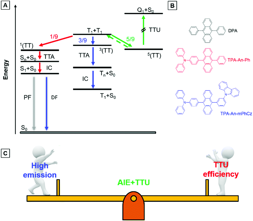 | ||
| Fig. 1 (A) Energy-level diagram illustrating the mechanisms of triplet–triplet upconversion (TTU) and triplet–triplet annihilation (TTA). 1(TT), 3(TT), and 5(TT) are the singlet, triplet, and quintet intermediate states. S1, T1, and S0 are singlet excitons, triplet excitons, and ground states. Sn and Tn are higher singlet and triplet states. (B) Chemical structures of the anthracene derivatives. (C) Design principle of the blue emitters. | ||
9,10-Diphenylanthracene (DPA), a polycyclic aromatic hydrocarbon (PAH) compound with a low triplet energy level and good stability, is typically used as an emitter for the construction of blue TTU OLEDs.13 In principle, TTU is a bimolecular process and needs a high enough triplet exciton concentration to improve the TF efficiency. However, DPA is usually doped into appropriate host materials due to its aggregation-caused quenching (ACQ) effects.14 As a result, it is difficult for the doped devices to achieve high-performance blue OLEDs by controlling the TF process. More importantly, preparation of the doped devices is complicated. Therefore, developing PAH compounds with intense emission in the film state is beneficial for the construction of high-performance non-doped blue TTU-OLEDs.
Exactly opposite to the ACQ effect, luminogens with aggregation-induced emission characteristics (AIEgens) can exhibit intense emission in their film states.15 Thus, they are ideal candidates to combine PAH compounds with TTU features to solve the above problems. According to our reported design strategy, new AIEgens, decorated ACQ molecules with a triphenylamine (TPA) moiety, have also been achieved.16 In addition, Konishi et al. illustrated that the frontier orbitals of diarylamine and anthracene interpenetrated when the planar donor was distorted,17 meanwhile, a transition between molecular orbitals with relative orthogonal directions might also promote the conversion process from 3(TT) to S1.12
Herein, the compounds TPA-An-Ph and TPA-An-mPhCz, in which the twisted donating groups of triphenylamine (TPA) was attached on anthracene (An) cores together with the meta-positions substituted planar group of the carbazole (Cz) moiety in the latter, were designed and synthesized (Fig. 1B). The carbazole group can facilitate the hole transport of devices, which in turn improves the device performance.18 In addition, it was demonstrated that high-efficiency emission in the solid state can be achieved using the meta-substituted strategy.19 Thanks to their AIE features, TPA-An-Ph and TPA-Ph-mPhCz show high photoluminescence quantum efficiency yields (PLQYs, ΦF) in their film states. The non-doped OLEDs using these AIEgens as emitting layers (EMLs) show blue emission and exhibit low efficiency roll off. The TPA-An-Ph-based OLED gives a maximum forward-viewing external quantum efficiency (EQE) of 4.51%. Notably, the TPA-An-mPhCz-based OLED achieves a maximum EQE of 8.1%. The transient electroluminescence (EL) spectra and theoretical calculations suggest that this could be ascribed to the effective TTU conversion process from 3(TT) to Sn of TPA-An-mPhCz. This strategy might provide an instructive way to achieve highly efficient commercialized blue OLEDs using the construction of AIEgens with an effective TTU process (Fig. 1C).
The synthetic routes to TPA-An-Ph and TPA-An-mPhCz are shown in Scheme S1 (ESI†). They could be facilely synthesized in 80% yields using the Suzuki coupling reaction. The structures of TPA-An-Ph and TPA-An-mPhCz were fully characterized using 1H and 13C NMR and high resolution mass (HRMS) spectroscopies. For comparison, the commercialized DPA was used to explore the rationality of the design. DPA, TPA-An-Ph and TPA-An-mPhCz are soluble in commonly used organic solvents, such as dichloromethane (DCM) and tetrahydrofuran (THF), but insoluble in water.
After confirming their structures, the photophysical properties of DPA, TPA-An-Ph and TPA-An-mPhCz were studied. Fig. 2A shows their ultraviolet-visible (UV-vis) absorption spectra in THF solutions. The absorption band at 360–400 nm could readily be assigned to the π–π* transition of the anthracene core.20 The PL spectra of DPA, TPA-An-Ph and TPA-An-mPhCz in THF solutions exhibit deep blue and blue emissions with peaks ranging from 409 to 476 nm upon photoexcitation (Fig. S1, ESI†). In comparison with DPA in a THF solution, the emission peaks of TPA-An-Ph and TPA-An-mPhCz were considerably red-shifted because of the enlongation of the conjugation. Meanwhile, featureless PL spectra were obtained for TPA-An-Ph and TPA-An-mPhCz in THF solutions, implying that each emission originates from the charge transfer (CT) state. The PL spectra of the vacuum-deposited neat films of DPA, TPA-An-Ph, and TPA-An-mPhCz show deep blue and blue emission with peaks at 442, 460 and 470 nm, respectively (Fig. 2B). The ΦF value of DPA in a THF solution was 68.1%, but reduced to 59.3% in the vacuum-deposited neat film. Notably, the ΦF values of TPA-An-Ph and TPA-An-mPhCz in THF solutions were measured to be 30.0 and 57.8%, and further enhanced to 40.1% and 65.1% in their vacuum-deposited neat films, respectively. These results suggest that TPA-An-Ph and TPA-An-mPhCz exhibit the aggregation-enhanced emission (AEE) feature.
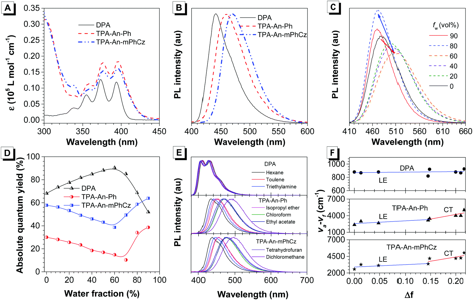 | ||
| Fig. 2 (A) UV-Vis (THF solution) and (B) photoluminescence (PL, film state) spectra of DPA, TPA-An-Ph, and TPA-An-mPhCz. (C) PL spectra of TPA-An-mPhCz in THF/water mixtures with different water fractions (fw); λex: 360 nm; concentration: 10 μM. (D) Absolute photoluminescence quantum yield of DPA, TPA-An-Ph, and TPA-An-mPhCz versus water fractions in THF/water mixtures. (E) Effects of solvent on the fluorescence spectra of the anthracene derivatives. (F) Stokes shifts of the anthracene derivatives as a function of the orientation polarizability. The solid lines are the fitting results using the Lippert–Mataga equation. | ||
To further explore the AEE feature of TPA-An-Ph and TPA-An-mPhCz, their PL behavior was explored in THF/water mixtures with different water fractions (fw). As shown in Fig. 2C and Fig. S2 (ESI†), the emission peaks slowly red-shifted along with the decrease in PL intensity when fw was gradually increased, which is attributed to the process of twisted intramolecular charge transfer (TICT).21 However, when the fw was further increased, their PL gradually intensified along with the blue-shifted emission peak owing to the formation of aggregates and activation of the restriction of intramolecular motion (RIM).22 In contrast with TPA-An-Ph and TPA-An-mPhCz, the ΦF values of DPA in THF/water mixtures with different fw show a completely opposite trend (Fig. 2D), which further demonstrated the effectiveness of our design strategy.
To concretely analyze the excited states of DPA, TPA-An-Ph and TPA-An-mPhCz, their PL spectra were investigated in different solvents (Fig. 2E). According to the Lippert–Mataga model,23 the dipole moments of their excited state can be acquired using the slope of the Stokes shift (va–vf) as a function of the orientation polarizability (f) as shown in Tables S1–S3 (ESI†). The fitting results are shown in Fig. 2F. The derived dipole moment (μe) of the excited state of DPA is 0.69 D, indicating that its excited state could be assigned to the localized excited (LE) state. While, TPA-An-Ph and TPA-An-mPhCz exhibit two independent slopes: smaller μe values of 7.27 and 9.02 D in low polarity solvents and larger μe values of 12.93 and 14.95 D in highly polar solvents, respectively. These results suggest that their excited states are assigned to the LE and CT states, respectively. Furthermore, their PL spectra in the film state were measured at 77 K (Fig. S3, ESI†), and the peaks of DPA, TPA-An-Ph and TPA-An-mPhCz were recorded to be 424 nm (2.92 eV), 454 nm (2.73 eV), and 467 nm (2.66 eV), respectively. The PL spectra of TPA-An-Ph and TPA-An-mPhCz in the film state are close to those in the polar solvents rather than those in nonpolar solvents. Therefore, the S1 states of the TPA-An-Ph and TPA-An-mPhCz films could be assigned to a 1CT mixing weak 1LE state. Moreover, the PL decay curves of DPA, TPA-An-Ph and TPA-An-mPhCz were plotted in Fig. S4 (ESI†). Their lifetime shows a single-exponential decay process in the THF solutions and solid films, suggesting that they emit fluorescence.
To have a deeper understanding of the structure–property relationship, a single crystal of TPA-An-mPhCz (CCDC 2042010†) was obtained via a solvent evaporation method and analyzed using X-ray diffraction crystallography. As shown in Fig. 3A, TPA-An-mPhCz possesses a highly twisted L-shape molecular configuration with large dihedral angles distributed between 61° and 81°. Moreover, strong multiple intermolecular C–H⋯π hydrogen bonds with short distances of 2.702–3.721 Å are found between the molecules (Fig. 3B). Notably, no close π–π stacking interaction was found in Fig. 3C and D. These factors can effectively rigidify the molecular conformation and reduce non-radiative energy dissipation in the aggregate state, resulting in an AEE effect.24
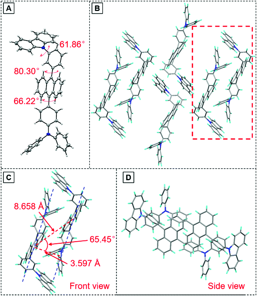 | ||
| Fig. 3 (A) Crystal structure and (B) packing pattern of TPA-An-mPhCz single crystals; (C) front view and (D) side view of the detailed molecular stacking within the red dotted line. | ||
Besides their high ΦF values in the film states, TPA-An-Ph and TPA-An-mPhCz are thermally stable according to the differential scanning calorimetry (DSC) and thermogravimetric analysis (TGA) measurements. As depicted in Fig. S5 and Table S4 (ESI†), the decomposition temperatures (Td, 5% weight loss) of TPA-An-Ph and TPA-An-mPhCz are 362 and 411 °C, respectively, and no glass transition temperatures (Tg) were found in the measurement region. These results suggest that they are suitable for the preparation of vapor deposition devices. In addition, the electrochemical properties of TPA-An-Ph and TPA-An-mPhCz were measured using cyclic voltammetry (CV). As shown in Fig. S6 (ESI†), the highest occupied molecular orbital (HOMO) energy levels of TPA-An-Ph and TPA-An-mPhCz are deduced to be −5.20 and −5.22 eV, and their lowest unoccupied molecular orbital (LUMO) energy levels are −2.51 and −2.52 eV, respectively, which will facilitate the device configuration optimization.
Thanks to the excellent thermal stability and the high emission efficiency in the aggregate/film states, the non-doped devices B1 and B2 were constructed using TPA-An-Ph and TPA-An-mPhCz as EMLs, respectively, with a device configuration of ITO/HAT-CN (5 nm)/TAPC (60 nm)/TCTA (5 nm)/EMLs (20 nm)/TmPyPB (40 nm)/LiF (1 nm)/Al (Fig. 4A), where ITO, 1,4,5,8,9,11-hexaazatriphenylene-hexacarbonitrile (HAT-CN), 1-bis[4-[N,N-di(4-tolyl)amino]-phenyl]-cyclo-hexane (TAPC), 4,4′,4′′-tri(N-carbazolyl)-triphenylamine (TCTA), and 1,3,5-tri[(3-pyridyl)-phen-3-yl]benzene (TmPyPB) act as the anode, hole injector, hole-transporter, exciton-blocking layer, and electron-transporting layer, respectively. These non-doped OLEDs emit blue light and exhibit excellent device performance at low operation voltages (Fig. 4B). It is worth noting that the EL spectra remain stable when the voltage increased from 3 to 8 V, confirming their good color stability (Fig. 4C and Fig. S7, ESI†). Moreover, device B2 presents an emission peak at 470 nm with a narrow full width at half-maximum (FWHM) of 58 nm, which is useful for blue emission of OLEDs. As depicted in Fig. 4D, device B1 achieves a maximum forward-viewing EQE of 4.51% and a CE of 5.54 cd A−1. Whereas, B2 gives a maximum EQE of 8.10% and a CE of 10.62 cd A−1. More importantly, the EQE and CE of B2 also remain high at values of 6.97% and 9.09 cd A−1 at a luminance of 1000 cd m−2, demonstrating the low efficiency roll-off of the device. Meanwhile, the power efficiency of these devices shows identical results (Fig. S8 and Table S5, ESI†).
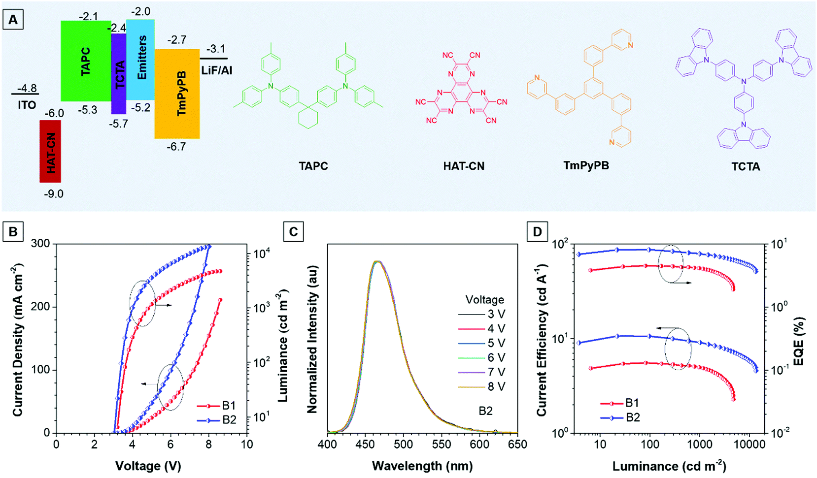 | ||
| Fig. 4 (A) Device structure and ionization potentials (IPCV) and electron affinities (EACV) for each material. (B) Current density–voltage–luminance (J–V–L) characteristics of devices B1 and B2. (C) Electroluminescence (EL) spectra of device B2 at various voltages. (D) CE and EQE versus luminance curves of the non-doped OLEDs based on the AIEgens TPA-An-Ph and TPA-An-mPhCz. | ||
Meanwhile, the doped devices were also fabricated with a configuration of ITO/HAT-CN (5 nm)/TAPC (60 nm)/TCTA (5 nm)/EML (20 nm)/TmPyPB (40 nm)/LiF (1 nm)/Al using 2,6-bis(3-(9H-carbazol-9-yl)phenyl)pyridine (26DCZPPy) as the host and TPA-An-mPhCz as the guest with different doping concentrations (device 1![[thin space (1/6-em)]](https://www.rsc.org/images/entities/char_2009.gif) :10%, device 2:20%, and device 3:50%). As shown in Table S6 (ESI†), the TPA-An-mPhCz based doped devices show blue emission with EL peaks at 458, 462 and 474 nm at low operation voltages, respectively (Fig. S9A and B, ESI†). Among the fabricated doped OLEDs, device 3 achieves a maximum EQE of 5.60%, a CE of 7.82% and a PE of 5.85%. These EL spectra remain stable when the voltage increased from 4 to 7 V, confirming their good color stability (Fig. S10, ESI†). However, these values are far behind those of device B2 (Fig. S9C, D and S11, ESI†), suggesting the advantages of non-doped OLEDs using AIEgens as EMLs.
:10%, device 2:20%, and device 3:50%). As shown in Table S6 (ESI†), the TPA-An-mPhCz based doped devices show blue emission with EL peaks at 458, 462 and 474 nm at low operation voltages, respectively (Fig. S9A and B, ESI†). Among the fabricated doped OLEDs, device 3 achieves a maximum EQE of 5.60%, a CE of 7.82% and a PE of 5.85%. These EL spectra remain stable when the voltage increased from 4 to 7 V, confirming their good color stability (Fig. S10, ESI†). However, these values are far behind those of device B2 (Fig. S9C, D and S11, ESI†), suggesting the advantages of non-doped OLEDs using AIEgens as EMLs.
It is worth noting that the EQE of device B2 breaks through the theoretical limit (5%) of pure fluorescent OLEDs. Theoretically, the EQE equals ηeh × ηPL × ηexciton × ηout, where ηeh is the factor of the recombination efficiency of injected holes and electrons (ideally 100%), ηPL is the absolute ΦF of the emitter (65.1% for the vacuum evaporated films of TPA-An-mPhCz), ηexciton is the radiative exciton ratio, and ηout is the light out-coupling efficiency. We measured the angle-dependent PL of TPA-An-mPhCz, but no data were obtained. Therefore, ηout is assumed to be 20%. According to the above equation, the ηexciton value of the non-doped OLED is calculated to be 62.2% using TPA-An-mPhCz as the EML, which is suggestive of the involvement of triplet excitons in the radiative process.
To verify the improved mechanism in the EL efficiency of the TPB–An–mPhCz-based OLED, we first measured the fluorescence lifetime of the TPA-An-mPhCz film, which shows a single-exponential decay process with the value of 3.58 ns. Then, we obtained its T1 energy level by measuring its phosphorescent spectrum according to a reported method,20 which is deduced to be 1.76 eV (Fig. S12, ESI†). These results suggest that TPA-An-mPhCz possesses a large energy gap between S1 and T1. Therefore, TADF was excluded from the high performance OLED.
Next, the transient EL decay of the non-doped device at different voltages was analyzed. As shown in Fig. 5A, the EL decay exhibits two parts, the prompt fluorescence and the delayed fluorescence. Triplet excitons return directly to higher excited singlet states, which results in no delayed component in the transient EL spectra of the hybridized local and charge transfer (HLCT)-OLEDs.23 Thus, the emission mechanism should be TTU. The prompt part originates from singlet exciton emission under electrical pumping, and the following delayed component is attributed to triplet excitons via the TF process. Moreover, the ratio of delayed fluorescence slowly decreases with increasing voltage. It is hypothesized that the delayed portion is not simply from the recombination of the trapped charges.11b As reported by Kondakov et al., the delayed EL is proportional to t−2 (t is the time) when TTU is predominant in the OLED.25 The plot of log(EL intensity) versus log(t) for device B2 is shown in Fig. 5B. The slope of the obtained curve is nearly −2, which is consistent with the TTU-related triplet exciton dynamics described above, further confirming the existence of a TTU process in the TPA-An-mPhCz-based OLED.
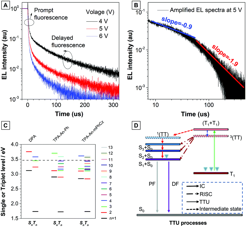 | ||
| Fig. 5 (A) Transient EL decay of the non-doped device B2 at different voltages. (B) Amplified EL spectra of the non-doped device B2 at 5 V. (C) Energy diagrams. Energy levels and twice the T1 energies (dashed line) of the anthracene derivatives calculated using B3LYP/6-311G(d,p), where n is the quantum number used to indicate the excited state. (D) Proposed TTU mechanism based on the emitters. | ||
To further confirm our assumptions, the excited states of DPA, TPA-An-Ph, and TPA-An-mPhCz were calculated using TD-DFT calculations based on the B3LYP/6-311(d,p) basis set. As shown in Fig. 5C, the T1 energy levels of DPA, TPA-An-Ph and TPA-An-mPhCz are all close to 1.73 eV, which is consistent with the results reported in the literature that were derived from the 3LE state of an anthracene unit.26 Thus, their 3(TT) are almost identical. In addition, the energy of 2T1 is higher than that of T2, indicating that ηTTU is close to 20% and in turn leading to an ηexciton value of 32.5%. However, the scenario cannot explain the maximum EQE of the TPA-An-mPhCz based OLED. Therefore, the possibility of a conversion process from 3(TT) to Sn (≤3) should be considered. According to previous work,12 the spin–orbit interaction between Sn and Tm whose energy levels are close to that of 3(TT) and in the range of 3.40–3.50 eV (Table S7, ESI†), should be taken into account. The TTU transition would form Sn and then return to S1via internal conversion. The possible TTU transitions from 3(TT) to Sn are given in Table S8 (ESI†). For TPA-An-Ph (Fig. S13, ESI†) and TPA-An-mPhCz (Fig. S14, ESI†), the TTU transition involves different vectors of the magnetic moments. For example, as depicted in Fig. S14 and Table S8 (ESI†), the spin–orbit matrix of 〈S3|Hso|T10〉 consisting of HOMO−2 and HOMO−4 are involved in the TTU transition from 3(TT) to Sn for TPA-An-mPhCz. The HOMO−4 is localized on the anthracene unit, whereas HOMO−2 is mainly localized on the carbazole unit, which is oriented perpendicularly to the anthracene unit. As a result, the rotation of the molecular orbitals from the carbazole unit to the anthracene unit is involved in the spin–orbit matrices, leading to a TTU process according to spin conversion, as illustrated in Fig. 5D. This process is different from HLCT and the “Hot” exciton process because the observed delayed fluorescence in OLEDs is derived from the TTU process.
Conclusions
Novel blue AIEgens of TPA-An-Ph and TPA-An-mPhCZ were designed and synthesized. They show excellent thermal stability and high ΦF in their film states. The non-doped OLEDs exhibit excellent device performance. The maximum CE and EQE of the TPA-An-mPhCz-based OLED can reach up to 10.62 cd A−1 and 8.10%, respectively, with an operation voltage as low as 3.0 V. More importantly, the CE and EQE still remain high at values of 9.09 cd A−1 and 6.97%, respectively, at a luminance of 1000 cd m−2, which is suggestive of a low efficiency roll-off of the device. The transient EL spectrum and theoretical calculations confirm that the unique TTU process of the emitter plays a crucial role in achieving the high EQE. The design strategy of a combination of the TTU process and AIE effect is valuable for the construction of high-performance OLEDs, which might be beneficial for practical applications, such as white lighting and full color, flat-panel displays.Author contributions
P. Han, A. Qin and B. Z. Tang conceived the original idea for investigation. P. Han, K. Wang, A. Qin and B. Z. Tang wrote the manuscript. P. Han synthesized the compounds. P. Han, and Y. Qiu measured the photophysical, thermal and electrochemical properties of the compounds. C. Lin and D. Ma fabricated and characterized the devices. P. Han performed the X-ray single crystal diffraction analysis. P. Han and H. Wu performed the quantum chemical calculations. All authors discussed the progress of research and reviewed the manuscript.Conflicts of interest
There are no conflicts to declare.Acknowledgements
This work was financially supported by the National Natural Science Foundation of China (21788102), the Natural Science Foundation of Guangdong Province (2019B030301003 and 2016A030312002), and the Innovation and Technology Commission of Hong Kong (ITC-CNERC14S01).References
- (a) C. W. Tang and S. A. VanSlyke, Appl. Phys. Lett., 1987, 51, 913–915 CrossRef CAS; (b) J. Kido, M. Kimura and K. Nagai, Science, 1995, 267, 1332–1334 CrossRef CAS PubMed; (c) Y. Sun, N. C. Giebink, H. Kanno, B. Ma, M. E. Thompson and S. R. Forrest, Nature, 2006, 440, 908–912 CrossRef CAS PubMed.
- W. Helfrich and W. G. Schneider, J. Chem. Phys., 1966, 44, 2902–2909 CrossRef CAS.
- (a) H. Kuo, Y. Chen, L. R. Devereux, C. Wu, M. A. Fox, C. Kuei, Y. Chi and G. Lee, Adv. Mater., 2017, 29, 1702464 CrossRef; (b) C. Adachi, M. A. Baldo, M. E. Thompson and S. R. Forrest, J. Appl. Phys., 2001, 90, 5048–5051 CrossRef CAS.
- A. Endo, M. Ogasawara, A. Takahashi, D. Yokoyama, Y. Kato and C. Adachi, Adv. Mater., 2009, 21, 4802–4806 CrossRef CAS PubMed.
- H. Uoyama, K. Goushi, K. Shizu, H. Nomura and C. Adachi, Nature, 2012, 492, 234–238 CrossRef CAS.
- (a) J. U. Kim, I. S. Park, C. Chan, M. Tanaka, Y. Tsuchiya, H. Nakanotani and C. Adachi, Nat. Commun., 2020, 11, 1–8 Search PubMed; (b) K. Tuong, Ly, R. Chen-Cheng, H. Lin, Y. Shiau, S. Liu, P. Chou, C. Tsao, Y. Huang and Y. Chi, Nat. Photonics, 2017, 11, 63–68 CrossRef; (c) J. Lee, C. Chen, P. Lee, H. Lin, M. Leung, T. Chiu and C. Lin, J. Mater. Chem. C, 2019, 7, 5874–5888 RSC.
- (a) C. Ganzorig and M. Fujihira, Appl. Phys. Lett., 2002, 81, 3137–3139 CrossRef CAS; (b) D. Y. Kondakov, T. D. Pawlik, T. K. Hatwar and J. P. Spindler, J. Appl. Phys., 2009, 106, 124510 CrossRef.
- (a) A. Salehi, C. Dong, D. Shin, L. Zhu, C. Papa, A. Thy Bui, F. N. Castellano and F. So, Nat. Commun., 2019, 10, 1–9 CrossRef CAS PubMed; (b) J. Huh, Y. H. Ha, S. Kwon, Y. Kim and J. Kim, ACS Appl. Mater. Interfaces, 2020, 12, 15422–15429 CrossRef CAS; (c) X. Qiao and D. Ma, Mater. Sci. Eng., R, 2020, 139, 100519 CrossRef.
- (a) C. Chiang, A. Kimyonok, M. K. Etherington, G. C. Griffiths, V. Jankus, F. Turksoy and A. P. Monkman, Adv. Funct. Mater., 2013, 23, 739–746 CrossRef CAS; (b) T. L. Keevers and D. R. McCamey, Phys. Rev. B, 2016, 93, 045210 CrossRef; (c) B. H. Wallikewitz, D. Kabra, S. Gélinas and R. H. Friend, Phys. Rev. B: Condens. Matter Mater. Phys., 2012, 85, 045209 CrossRef.
- Y. Y. Cheng, T. Khoury, R. G. C. R. Clady, M. J. Y. Tayebjee, N. J. Ekins-Daukes, M. J. Crossley and T. W. Schmidt, Phys. Chem. Chem. Phys., 2010, 12, 66–71 RSC.
- (a) D. Di, L. Yang, J. M. Richter, L. Meraldi, R. M. Altamimi, A. Y. Alyamani, D. Credgington, K. P. Musselman, J. L. MacManus-Driscoll and R. H. Friend, Adv. Mater., 2017, 29, 1605987 CrossRef; (b) W. Liu, S. Ying, R. Guo, X. Qiao, P. Leng, Q. Zhang, Y. Wang, D. Ma and L. Wang, J. Mater. Chem. C, 2019, 7, 1014–1021 RSC.
- R. Ieuji, K. Goushi and C. Adachi, Nat. Commun., 2019, 10, 5283 CrossRef PubMed.
- R. Sato, H. Kitoh-Nishioka, K. Kamada, T. Mizokuro, K. Kobayashi and Y. Shigeta, J. Phys. Chem. C, 2018, 122, 5334–5340 CrossRef CAS.
- J. Yang, Z. Chi, W. Zhu, B. Z. Tang and Z. Li, Sci. China Chem., 2019, 62, 1090–1098 CrossRef CAS.
- (a) Z. Zhao, H. Zhang, J. W. Y. Lam and B. Z. Tang, Angew. Chem., Int. Ed., 2020, 59, 2–22 CrossRef; (b) J. Yang, M. Fang and Z. Li, Aggregate, 2020, 1, 6–18 CrossRef.
- J. Mei, N. L. C. Leung, R. T. K. Kwok, J. W. Y. Lam and B. Z. Tang, Chem. Rev., 2015, 115, 11718–11940 CrossRef CAS.
- S. Sasaki, S. Suzuki, W. M. C. Sameera, K. Igawa, K. Morokuma and G. Konishi, J. Am. Chem. Soc., 2016, 138, 8194–8206 CrossRef CAS.
- P. Han, C. Lin, D. Ma, A. Qin and B. Z. Tang, ACS Appl. Mater. Interfaces, 2020, 12, 46366–46372 CrossRef CAS.
- H. Liu, D. Cong, B. Li, L. Ye, Y. Ge, X. Tang, Y. Shen, Y. Wen, J. Wang, C. Zhou and B. Yang, Cryst. Growth Des., 2017, 17, 2945–2949 CrossRef CAS.
- X. Tang, Q. Bai, T. Shan, J. Li, Y. Gao, F. Liu, H. Liu, Q. Peng, B. Yang, F. Li and P. Lu, Adv. Funct. Mater., 2018, 28, 1705813 CrossRef.
- R. Hu, E. Lager, A. Aguilar-Aguilar, J. Liu, J. W. Y. Lam, H. H. Y. Sung, I. D. Williams, Y. Zhong, K. S. Wong, E. Peña-Cabrera and B. Z. Tang, J. Phys. Chem. C, 2009, 113, 15845–15853 CrossRef CAS.
- H. Nie, K. Hu, Y. Cai, Q. Peng, Z. Zhao, R. Hu, J. Chen, S. Su, A. Qin and B. Z. Tang, Mater. Chem. Front., 2017, 1, 1125–1129 RSC.
- W. Li, Y. Pan, L. Yao, H. Liu, S. Zhang, C. Wang, F. Shen, P. Lu, B. Yang and Y. Ma, Adv. Opt. Mater., 2014, 2, 892–901 CrossRef CAS.
- J. Guo, X. Li, H. Nie, W. Luo, S. Gan, S. Hu, R. Hu, A. Qin, Z. Zhao, S. Su and B. Z. Tang, Adv. Funct. Mater., 2017, 27, 1606458 CrossRef.
- D. Y. Kondakov, J. Appl. Phys., 2007, 102, 114504 CrossRef.
- S. Reineke and M. A. Baldo, Sci. Rep., 2014, 4, 3797 CrossRef PubMed.
Footnote |
| † Electronic supplementary information (ESI) available. CCDC 2042010. For ESI and crystallographic data in CIF or other electronic format see DOI: 10.1039/d1mh01129d |
| This journal is © The Royal Society of Chemistry 2022 |