
 Open Access Article
 This Open Access Article is licensed under a Creative Commons Attribution-Non Commercial 3.0 Unported Licence
‘Template-free’ synthesis of self-assembled micro-spikes resulting in ‘sea-urchin’-like carbon structures for suppressing electromagnetic radiation†
Vidyashree
M. P.
a,
Kumari
Sushmita
 bc,
Kokila
M. K.
*a and
Suryasarathi
Bose
*b
bc,
Kokila
M. K.
*a and
Suryasarathi
Bose
*b
aDepartment of Physics, Bangalore University, Bangalore-560056, Karnataka, India. E-mail: drmkkokila@gmail.com
bDepartment of Materials Engineering, Indian Institute of Science Bangalore-560012, Karnataka, India. E-mail: sbose@iisc.ac.in
cCentre for Nano Science and Engineering, Indian Institute of Science, Bengaluru-560012, India
First published on 2nd August 2022
Abstract
We report the facile ‘template-free’ synthesis of self-assembled ‘micro-spikes’, resulting in sea-urchin-like carbon structures that can suppress incoming electromagnetic (EM) radiation, which may not be achievable with conventional flake-type dispersed composites. Herein, we synthesized ‘carbon-urchins’ (C-urchins) from the self-assembly of short carbon fibers (CFs) via a facile one-pot synthesis method and then incorporated them into an epoxy matrix to obtain high-performance EMI shielding materials. To gain mechanistic insight, the C-urchins were doped with different dopants, such as magnetic nano-Fe3O4 (C-F urchins), conducting nano-Ag particles (C-A urchins), and dielectric nano-SiO2 (C-S urchins), to evaluate the influence of the dopant on the EMI shielding performance. Interestingly, all three doped C-urchin types in an epoxy matrix showed excellent absorption-dominated shielding (>99%) in the K-band region, with shielding effectiveness (SET) of up to −32 dB. The spatial distribution of the C-urchins was controlled in the epoxy composites to achieve the highest SET values for the prepared composites. The thermal properties of the composites were similar to those of neat epoxy; however, the storage modulus was enhanced in the composites. To this end, while high loading of conducting filler is required to meet commercial standards, resulting in processing difficulties, C-urchin-filled composites can open up new avenues in this field. The micro-spikes of the C-urchins can scatter/absorb incoming EM radiation through coupling with the fields.
Introduction
Over the years, the rapid development and large-scale usage of advanced electronic devices, wireless communications, instruments in military and civil areas, etc., have made human life more convenient and comfortable. This huge dependence on electronic equipment has created a serious environmental problem in the form of electromagnetic interference (EMI).1,2 EMI refers to the interference of the electromagnetic signals from one electronic device with those of another device by means of radiated paths, conducted paths, or both.3 As a result, these unwanted electromagnetic signals may adversely affect the performance of nearby devices.4 EMI not only produces noise in signals, but it may also affect human health. Therefore, to minimize the impact of EMI, active research is ongoing to develop efficient EMI shielding materials capable of blocking EM radiation over a broad frequency range.1An EM wave consists of electric and magnetic components perpendicular to each other. The direction of the propagation of the EM wave is perpendicular to both the electric and magnetic components.5,6 EMI shielding takes place due to three phenomena: the reflection of the EM waves at the interface due to impedance mismatch; the absorption of EM waves within the shielding material due to conduction, dielectric and magnetic loss; and the multiple reflections of the EM wave within the shield at filler-polymer interfaces.7,8 Hence the total shielding effectiveness (SET) is contributed to by either one or a combination of these phenomena.9
Conventionally, metals and metallic composites have been used extensively as EMI shielding materials because of their high conductivity, which makes them good reflectors due to the availability of a large number of free electrons.10,11 The main drawback of using metals as shielding materials is that the electric field inside the metal is zero; therefore, the incoming EM waves are reflected/scattered back into the environment, which can further disturb the functioning of nearby devices. Apart from this, metals suffer from several other issues, like having a high density, being prone to corrosion, having poor chemical resistance, and creating processing difficulties. Even though metals allow excellent shielding, they are not very attractive when it comes to electronic devices, which are becoming thinner and lighter day by day.3,12 On the other hand, polymers rightly fit in this space owing to their light weight and ease of integration into existing processes, making them a potential candidate for designing composites with multifunctional properties. Epoxy is one of the most important classes of thermoset polymers, which are widely used for structural and high-performance applications due to their unique combination of thermal, mechanical, and electrical properties.13,14 Epoxy offers very high strength, superior adhesion to various substrates, corrosion resistance, chemical resistance, effective insulation in electronic devices, and good wetting properties, making it well suited for several applications.14 Hence these impressive characteristics of epoxy make it an ideal candidate for use in the composite industry.15–19 However, due to their insulating nature and lack of electric and magnetic dipoles, most polymers are transparent to EM waves. Epoxy is one such insulative polymer, and it exhibits SET of 0 dB. However, as already mentioned, epoxy has found several applications in the electronics and aerospace sectors, where EMI shielding is also required. Therefore, there is a need to incorporate certain magnetic/conducting/dielectric fillers to improve the EMI shielding properties of epoxy-based composites.20,21
To incorporate magnetic/conducting/dielectric fillers, researchers have opted for hybrid approaches or architectural tweaking. A single monolith with nano-flakes dispersed in a matrix is not amenable to meeting the stringent requirements; hence, research has focused on designing hybrid, core-shell, and multilayered structures.7,10,22,23 However, such strategies involve cumbersome synthesis procedures and too many parameters that require precise control. Among the various fillers that have been researched, carbon-based nanofillers, such as carbon nanotubes (CNTs), graphene, and carbon fibers (CFs), have attracted a great deal of attention for designing efficient shielding materials and effectively reinforcing composites.8,24–27 In carbonaceous derivatives, CFs have shown enormous potential for designing composites/laminates with key attributes like light weight, high tensile strength, high modulus values, low thermal expansion coefficients, and exceptional durability.19,28–30 In addition, carbon fibers also show excellent electrical and thermal properties, and they can be used for various applications depending on the requirements. Also, carbon fibers act as a waveguide and result in excellent shielding effectiveness in laminates/composites.31
To further enhance the shielding abilities of composites, metallic, magnetic, and dielectric nanoparticles are largely used. These fillers include Ag, Cu, Fe3O4, SiO2, ZnO, Fe, and their alloys. With the addition of dielectric and magnetic fillers, the absorption percentage during shielding can be enhanced.32–34 Epoxy/CF composites with CF modification have been extensively studied by researchers in the last decade. Gholampoor et al.35 prepared nano-Fe3O4 powder via a co-precipitation method and deposited this on CFs using an electrophoretic deposition (EPD) method; it was then incorporated into epoxy. They observed that the SET value for a 2 mm-thick sample was −23 dB in the range of 8.2–12.4 GHz for 20 wt% nano-Fe3O4/CF. Cheng et al.36 prepared Ag/CF/polyaniline (PANI) composites, with PANI particles wrapping the silver-plated CFs, via in-situ polymerization, and these were incorporated in epoxy. Here, Ag/CF was prepared via an electroless plating method. They observed that the epoxy composite with Ag/CF/PANI had homogenously dispersed filler and exhibited an SET value of −8 dB at 4.5 wt% loading for a 2 mm sample. Movassagh-Alanagh et al.37 introduced multi-walled carbon nanotubes and Fe3O4 nanoparticles onto CFs through an electrophoretic co-deposition process. Fe3O4/multiwall carbon nanotubes@CF was incorporated as a filler into epoxy resin. The sample exhibited an SET value of −35 dB with a thickness of 5 mm in the range of 8.2–18 GHz. There is limited literature on SiO2-decorated CFs for EMI shielding applications, but SiO2 has been extensively used for EMI shielding applications due to its dielectric loss properties.38–40 The primary objective of this work is to enhance the absorption-based EMI shielding performance of epoxy composites. Hence, as mentioned above, there should be a synergetic effect between the conducting, magnetic, and dielectric components. These materials will lead to better impedance matching on the surface, thus resulting in the reduction of the overall EM reflection.41,42
In light of this discussion, herein, we have designed lightweight epoxy-based composites with high absorption-based EMI shielding performance using sea-urchin-like carbon structures (C-urchins) derived from the self-assembly of short carbon fibers following the refluxing of the fibers under acidic conditions. To gain mechanistic insight, C-urchins were doped with magnetic nanoparticles (here Fe3O4), conducting nanoparticles (here Ag), or dielectric nanoparticles (here SiO2) to understand the role of dopants in influencing the EMI shielding performance in the composites. Dispersing carbon fibers is challenging in an epoxy matrix, as the viscosity beyond a certain concentration increases greatly, creating processing challenges. However, our strategy demonstrates that self-assembling carbon fibers to yield C-urchins is easy in terms of handling, and the spatial dispersion can be well controlled to tune the properties of the composite. The synthesis protocol adopted here is industrially scalable and can help guide researchers working in this area in both academia and industry.
Experimental section
Materials
Epoxy resin (bisphenol-F-epichlorohydrin, EPOLAM 8052) and an amine-based hardener (2,2′-dimethyl-4,4′methylene bis(cyclohexylamine)) were provided by Axson technologies (France). Short CFs with a length of 6 mm and diameter of about 7 μm were commercially obtained from SGL carbon company. Ferric chloride hexahydrate (FeCl3·6H2O; LR 98%) was obtained from Thomas Baker. Ethanol, hydrazine hydrate (H4N2·H2O; 99%), ethylene glycol (C2H6O2), urea (NH2CONH2), silver nitrate, liquid ammonia, and tetraethyl orthosilicate were procured from SDFCL.Synthesis of C-urchins
500 mg of pristine CFs was taken and added to acid solution (40 ml of distilled water and 360 ml of HNO3). The solution was bath-sonicated for 30 min and kept under stirring for 24 h at 80 °C in an oil bath. The resultant solution was filtered, washed repeatedly with distilled water, and kept in an oven at 80 °C for drying. The yield of C-urchins obtained is 99%. The preparation procedure of C-urchins is shown in Fig. 1.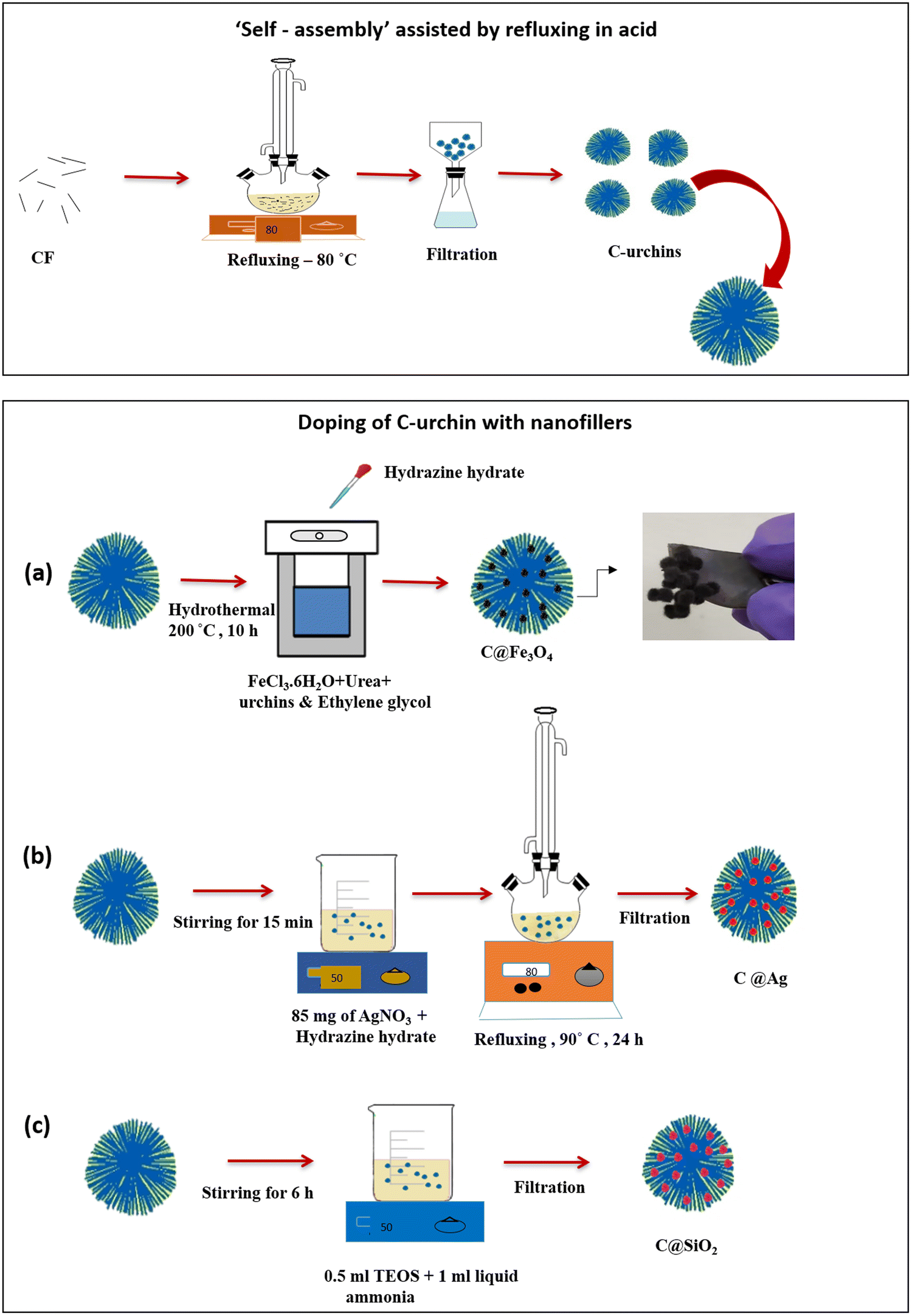 | ||
| Fig. 1 A schematic diagram illustrating the synthesis of sea-urchin-like carbon structures derived from the ‘self-assembly’ of carbon fibers assisted by refluxing in an acid medium. The synthesis of (a) carbon urchins doped with Fe3O4 nanoparticles; (b) carbon urchins doped with Ag nanoparticles; and (c) carbon urchins doped with SiO2 nanoparticles. The inset of (a) shows the magnetic nature of carbon urchins doped with Fe3O4 nanoparticles. | ||
![[thin space (1/6-em)]](https://www.rsc.org/images/entities/char_2009.gif) :37) were kept mixing for 15 min. For the adequate dispersion of filler in the polymer matrix, mechanical mixing was performed using an overhead stirrer (Heidolph RZR 2102) at 500 rpm. The mixture was kept under vacuum to remove air bubbles. Once the bubbles were removed, epoxy composites were prepared via varying the spatial distribution of fillers (i.e., different types of C urchins). Then, the mixture of epoxy and hardener (prepared in the previous step) was carefully poured into a Teflon-coated aluminum mold. A bed of urchins was arranged manually in the mold first with no overlap, as is shown in Fig. 2. The mold was then kept in the oven for curing and post-curing. It was pre-cured at 60, 80, and 100 °C for 1 h each, followed by post-curing at 120 °C for 2 h.46 The sample codes for easy representation are as follows: C-urchins close (which means closely packed), C-urchins far (loosely packed), C-F urchins (closely packed), C-A urchins (closely packed), and C-S urchins (closely packed). Rectangular samples were fabricated for dynamic mechanical analysis (DMA) and EMI shielding and electrical conductivity measurements.
:37) were kept mixing for 15 min. For the adequate dispersion of filler in the polymer matrix, mechanical mixing was performed using an overhead stirrer (Heidolph RZR 2102) at 500 rpm. The mixture was kept under vacuum to remove air bubbles. Once the bubbles were removed, epoxy composites were prepared via varying the spatial distribution of fillers (i.e., different types of C urchins). Then, the mixture of epoxy and hardener (prepared in the previous step) was carefully poured into a Teflon-coated aluminum mold. A bed of urchins was arranged manually in the mold first with no overlap, as is shown in Fig. 2. The mold was then kept in the oven for curing and post-curing. It was pre-cured at 60, 80, and 100 °C for 1 h each, followed by post-curing at 120 °C for 2 h.46 The sample codes for easy representation are as follows: C-urchins close (which means closely packed), C-urchins far (loosely packed), C-F urchins (closely packed), C-A urchins (closely packed), and C-S urchins (closely packed). Rectangular samples were fabricated for dynamic mechanical analysis (DMA) and EMI shielding and electrical conductivity measurements.
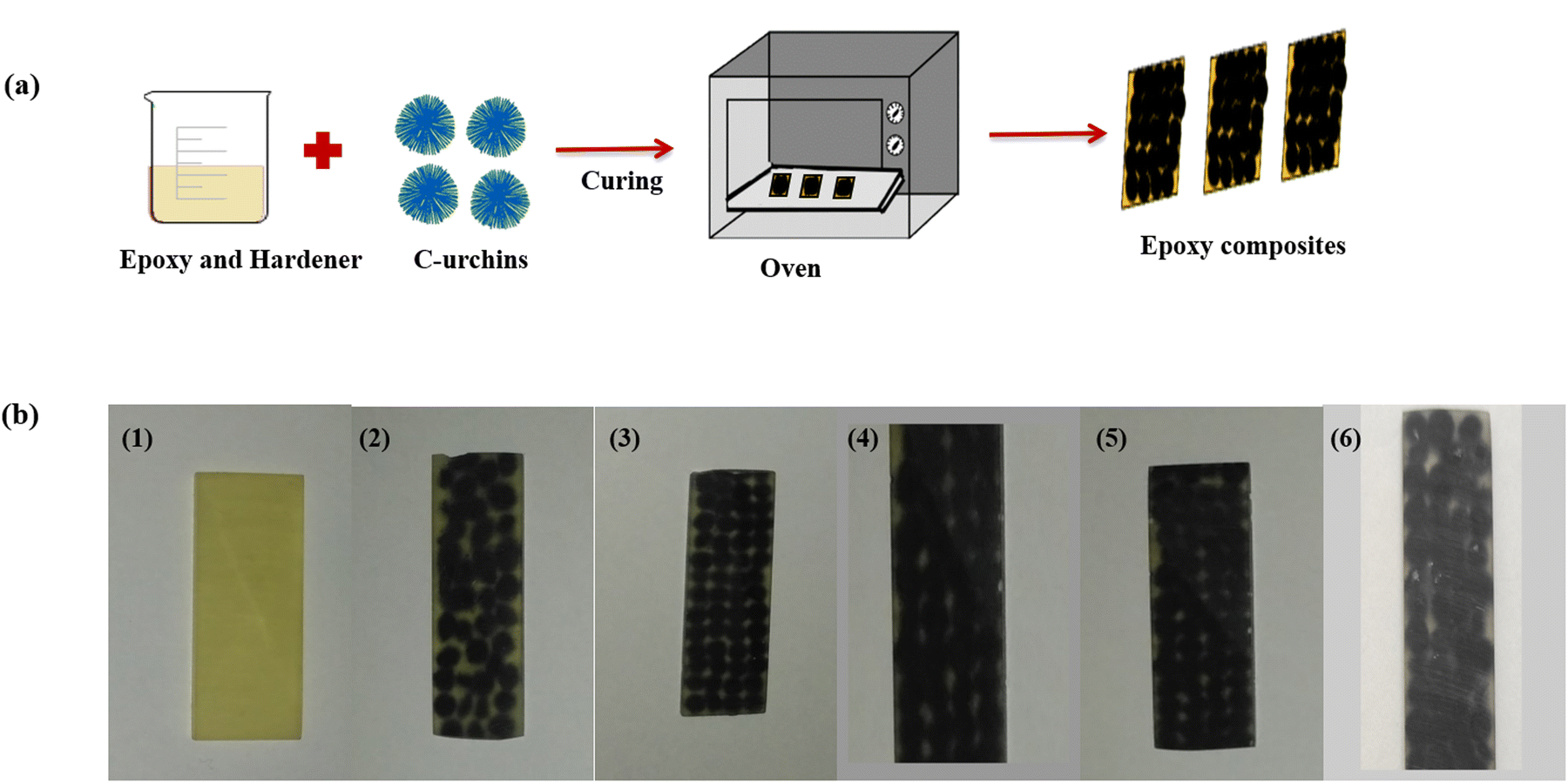 | ||
| Fig. 2 (a) A schematic diagram illustrating the preparation of C-urchin/epoxy composites. (b) Digital photographs of the prepared composites: (1) neat epoxy, (2) C-urchins loosely packed, (3) C-urchins closely packed, (4) C-F urchins (closely packed), (5) C-A urchins (closely packed), and (6) C-S urchins (closely packed). | ||
Characterization
The doping of magnetic, conducting, or dielectric particles onto C-urchins was confirmed via scanning electron microscopy and X-ray diffraction. XRD analysis was performed using XPERT Pro apparatus from PANalytical in the 2θ range of 5–80°, using a CuKα radiation source (λ = 1.5406 Å, 40 kV, and 30 mA). The carboxylic functionalization of C-urchins was confirmed via Fourier-transform infrared (FTIR) spectroscopy using a PerkinElmer GX spectrometer in the range of 4000–400 cm−1. The decoration of Fe3O4, Ag, and SiO2 onto CFs was assessed using field-emission scanning electron microscopy (FESEM, model-ULTRA 55, bought from Carl Zeiss). Energy dispersive X-ray spectroscopy (EDS) analysis was carried out to obtain a rough estimate of the percentage of filler on the C-urchins. Thermal degradation studies of epoxy composites were performed using a thermogravimetric analyzer (TGA, model-Q500, bought from TA instruments) in the temperature range of 30–900 °C in a nitrogen environment. Dynamic mechanical thermal analysis was done using a three-point bending clamp on a TA Q800 dynamic mechanical analyzer (DMA) in the temperature range of 35–200 °C at a constant vibrating frequency of 1 Hz and with an amplitude of 15 μm. The AC electrical conductivity was measured (specimen dimensions: diameter, 10 mm; thickness, 1 mm) using an impedance analyzer (Alpha-A analyzer bought from Novocontrol, Germany) over a broad frequency range of 10−1 to 107 Hz at room temperature. Limiting oxygen index (LOI) tests were carried out according to ASTM D2863 standards using apparatus bought from Concept Equipment Ltd, UK. For LOI testing, first the sample was mounted on a holder, followed by ignition using a burner, and then measurements were recorded. For heat dissipation measurements, the sample was heated with a laser with a wavelength of 808 nm for 50 s and then the laser was switched off and the sample was allowed to cool for 50 s. IR imaging was done using an IR camera (brought from FLUKE). EMI shielding measurements were carried out using a Keysight (model: Fieldfox microwave analyzer N9918A) vector network analyzer (VNA) in a broadband frequency range (8.2 to 26.5 GHz) at room temperature. The scattering parameters (S11, S12, S21, and S22) obtained from VNA are used to evaluate the total shielding effectiveness (SET) and shielding effectiveness from absorption (SEA) and reflection (SER). The magnetic properties were studied at room temperature (with an applied field of −40000 to 40000 Oe) using a vibrating sample magnetometer (VSM) bought from Lakeshore.
Results and discussion
Structural and spectroscopic analysis
The structures of C-urchins, C-F urchins, C-A urchins, and C-S urchins were assessed using XRD. The XRD patterns of the materials are shown in Fig. 3a. C-urchins showed a peak at around 25°, which corresponds to the (002) plane of carbon fibers.43 In the XRD pattern of C-F urchins, five additional peaks were observed at 30.56°, 36.03°, 43.6°, 57.6°, and 63.3°, corresponding to the (220), (311), (400), (511), and (440) planes.47 These peaks can be attributed to the formation of Fe3O4 nanoparticles on C-urchins after the hydrothermal reaction. Similarly, the XRD pattern of C-A urchins shows four peaks at 38.1°, 44.3°, 64.4°, and 77.4°, which correspond to the (111), (200), (220), and (311) diffraction planes, respectively, of face-centered cubic (fcc) Ag nanoparticles.44 This is in accordance with the standard pattern (JCPDS card no 04-0783). For C-S urchins, the XRD pattern shows a characteristic amorphous hump at 23°, which can be attributed to SiO2 nanoparticles.48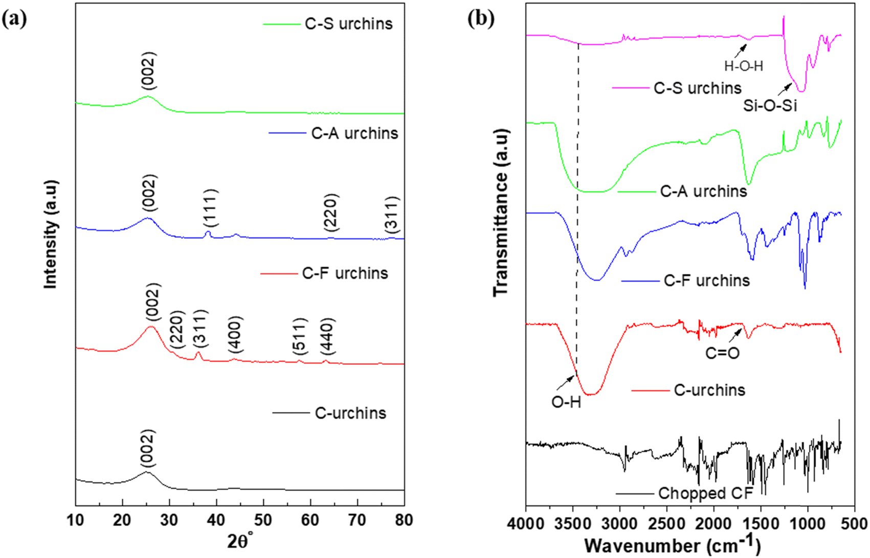 | ||
| Fig. 3 (a) XRD patterns of C-urchins, C-F urchins, C-A urchins, and C-S urchins. (b) FT-IR spectra of CFs, C-urchins, C-F urchins, C-A urchins, and C-S urchins. | ||
Fig. 3b shows the FTIR spectra of CF, C-urchins, C-F urchins, C-A urchins, and C-S urchins. The peak at 1704 cm−1 in the spectra of C-urchins and C-A urchins corresponds to C![[double bond, length as m-dash]](https://www.rsc.org/images/entities/char_e001.gif) O carbonyl stretching. The reduced intensity of carbonyl stretching in the spectra of C-F urchins and C-S urchins suggests the utilization of carboxylic groups during the synthesis of doped C-urchins. A peak appears in all urchin spectra at around 3458 cm−1, which corresponds to the stretching of hydrogen-bonded OH groups. The bands at around 1116 cm−1 and 1663 cm−1 in the spectra of C-S urchins correspond to H–O–H bending and Si–O–Si vibrations, respectively.49
O carbonyl stretching. The reduced intensity of carbonyl stretching in the spectra of C-F urchins and C-S urchins suggests the utilization of carboxylic groups during the synthesis of doped C-urchins. A peak appears in all urchin spectra at around 3458 cm−1, which corresponds to the stretching of hydrogen-bonded OH groups. The bands at around 1116 cm−1 and 1663 cm−1 in the spectra of C-S urchins correspond to H–O–H bending and Si–O–Si vibrations, respectively.49
Fig. 4(a) shows an SEM micrograph of CFs. Fig. 4(b and c) shows the ‘self-assembled’ micro-spikes resulting in a sea-urchin-like structure, and the higher magnification image of the urchins clearly shows that the microneedles could scatter/absorb radiation via coupling with incoming fields. Fig. 4(d–f) shows doped C-urchin with Fe3O4 (the presence of dopant can be clearly seen in high-magnification images). Fig. 4(g–i) depicts C-urchins doped with Ag, and Fig. 4(j–l) shows C-urchins doped with SiO2 (the presence of dopants can be seen in higher-magnification images). From these micrographs, the presence of dopants on the C-urchins is clearly evident. Fig. 5(a–e) compares the surface morphologies of CFs, C-urchins, C-F urchins, C-A urchins, and C-S urchins, and EDS mapping analysis is provided. It is observed that the surface of C-urchins is smooth, whereas in the case of urchins anchoring Fe3O4, Ag, or SiO2, white dots cover the surface of C-urchins, manifesting the presence of nanoparticles on the C-urchins after the reaction process. Estimates of the amounts of Fe3O4, Ag, and SiO2 on the C urchin surfaces are determined via EDS analysis, which showed 8.38 atomic% for Fe, 4.60 atomic% for Ag, and 26.35 atomic% for Si.
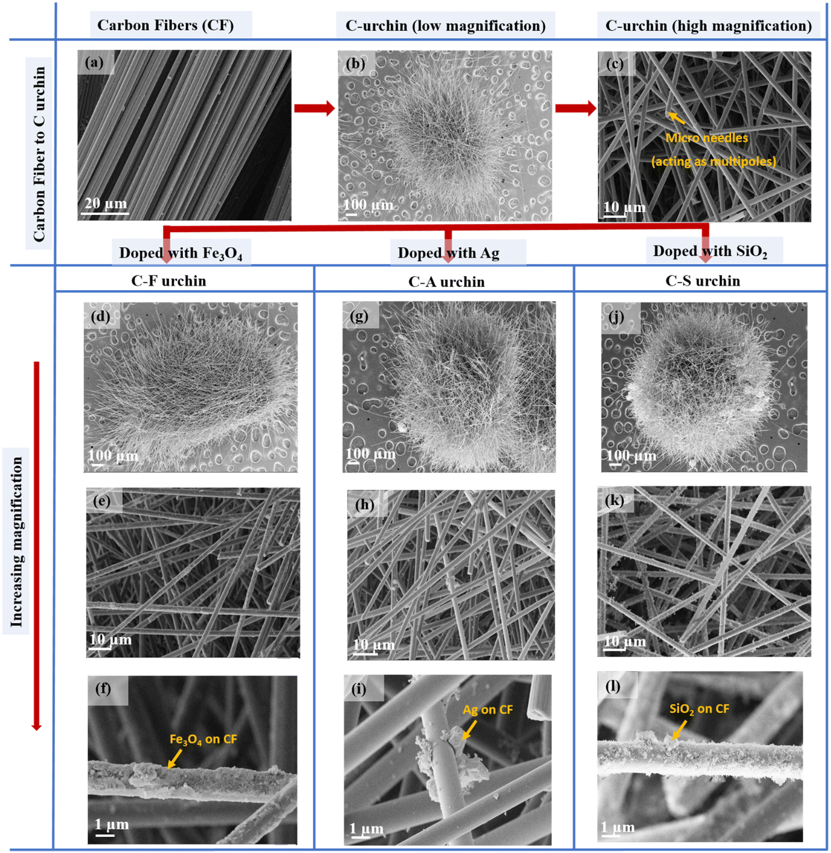 | ||
| Fig. 4 SEM micrographs: (a) CFs; (b) C-urchins; (c) C-urchins (high magnification), depicting the presence of microneedles acting as multipoles; (d–f) C-urchins doped with Fe3O4 (arranged by increasing magnification from top to bottom); (g–i) C-urchins doped with Ag (arranged by increasing magnification from top to bottom); and (j–l) C-urchins doped with SiO2 (arranged by increasing magnification from top to bottom). | ||
 | ||
| Fig. 5 SEM micrographs of (a) CFs, (b) C-urchins, (c) C-F urchins, (d) C-A urchins, and (e) C-S urchins with accompanying EDS elemental mapping analysis. | ||
 | ||
| Fig. 6 (a) TGA analysis of the epoxy composites. (b) The magnetic properties of C-F urchins embedded in an epoxy matrix. (c) VSM plots for C-F urchins and the C-F-urchin-based composite. | ||
The magnetic properties of C-F urchins and the epoxy composite containing C-F urchins were measured via VSM at room temperature. Fig. 6(c) shows the magnetic curves of C-F urchins and the C-F urchin composite. It can be observed that the saturation magnetization of the composites was reached rapidly. The saturation magnetization (Hs) and coercivity (Hc) of C-F urchins are 3.7 emu g−1 and 142.7 Oe, respectively, and those of the C-F urchin composite are 0.19 emu g−1 and 47.2 Oe, respectively. The Hs and Hc values of the C-F urchins are higher than the epoxy composite containing C-F urchins, which is as expected.
The mechanical properties of epoxy composites containing C-urchins and doped C-urchins were analyzed using DMA. Fig. 7 demonstrates the storage moduli and tanδ curves as a function of temperature for various epoxy composites. As seen in Fig. 7(a), it is observed that with the addition of C-urchins, C-F urchins, C-A urchins, and C-S urchins, the storage modulus reached 2117 MPa, 3074 MPa, 2858 MPa, and 2647 MPa, respectively, compared to neat epoxy, which showed a storage modulus of 2100 MPa. The enhancement in storage modulus in composites containing closely packed C-urchins is attributed to effective load transfer from epoxy to the filler material.17,51Fig. 7(b) shows the tanδ curves for the epoxy composites. Tg is around 135 °C for neat epoxy, whereas the Tg values for C-urchins, C-F urchins, C-A urchins, and C-S urchins were 137 °C, 142 °C, 142 °C, and 139 °C, respectively.
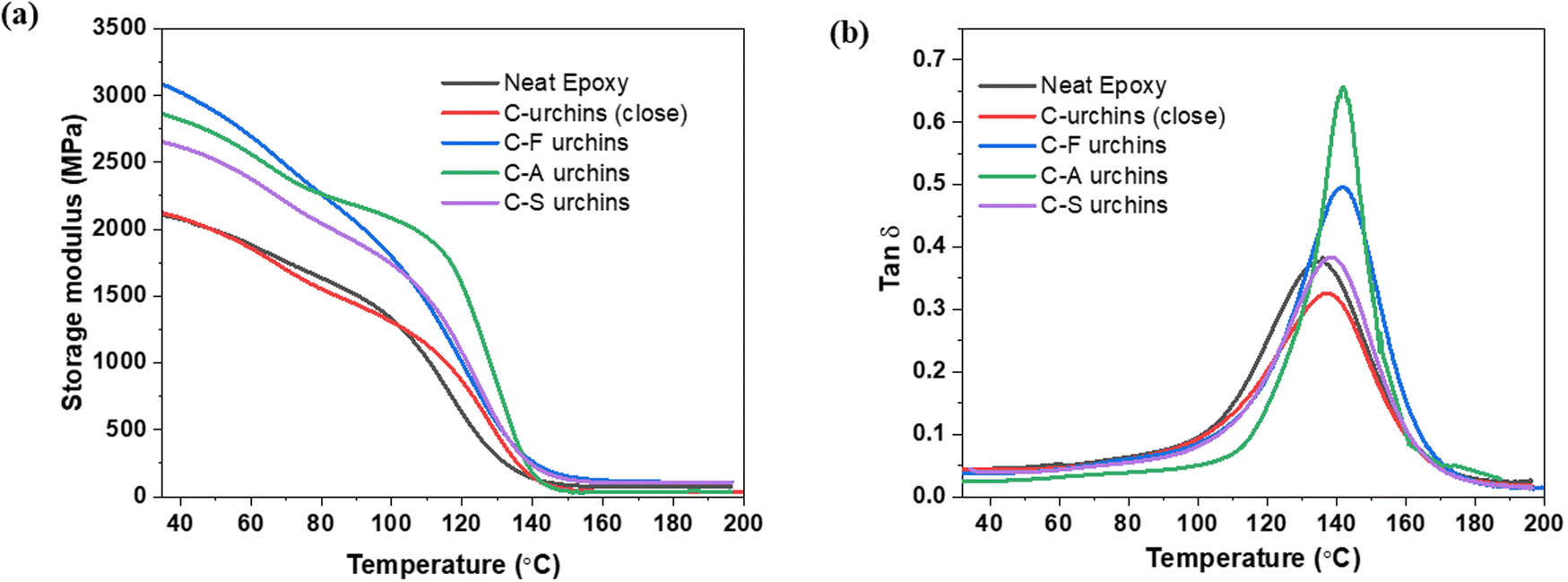 | ||
| Fig. 7 (a) Storage modulus and (b) tanδ plots of epoxy composites obtained from DMA analysis. | ||
The flame retardancy of the epoxy composites was determined using LOI testing, which ultimately gives the flammability behavior of polymeric materials. The epoxy resin is highly flammable and showed an LOI value of 21. The epoxy composites containing C-urchins, C-F urchins, C-A urchins, and C-S urchins showed improvement in the LOI value to 22. This indicates that the addition of C-urchins can also improve the flammability properties to some extent compared to neat epoxy.6
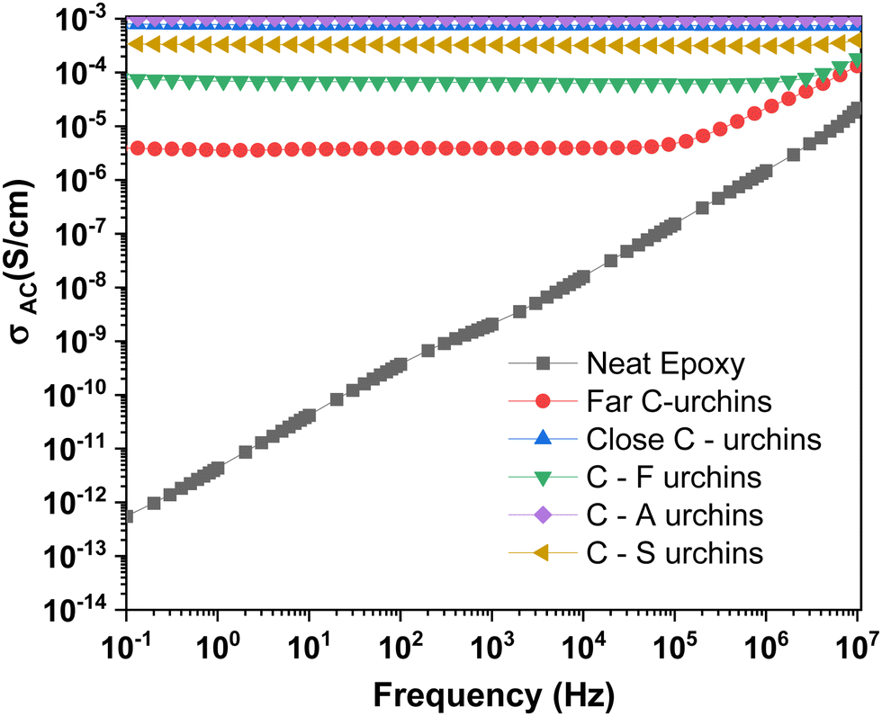 | ||
| Fig. 8 AC electrical conductivity values of the composites as a function of frequency. | ||
The Jonscher universal power law explains the frequency dependence of AC conductivity. According to the law, conducting filler in a polymer matrix can be modeled as a set of resistors and capacitors.12 A plot shows that the AC electrical conductivity of the capacitor increases with frequency, and the resistor exhibits a frequency-independent response. The AC electrical conductivity as a function of frequency can be expressed via the following equation:
| σ′(ω) = σ(0) + σAC(ω) = σDC + Aωs | (1) |
Since the host matrix (epoxy) is insulating in nature, the shielding efficiency depends on the network of conducting C-urchins or, more precisely, the spatial distribution of the urchins in the composite. From the data, the DC electrical conductivity values of the composites containing C-urchins that are closely packed, C-F urchins, C-A urchins, and C-S urchins are observed to be 7.04 × 10⁻⁴, 8.55 × 10⁻⁵, 1.06 × 10⁻³, and 3.50 × 10⁻⁴ S cm−1, respectively. Due to defects produced during harsh chemical refluxing (or during the hydrothermal reaction) in the case of doped C-urchins, we can conclude that the polarization centers thus generated can help in suppressing incoming EM radiation.
The closely packed urchins showed higher conductivity compared with other composites due to electron tunneling or hopping, as insulating epoxy at the interface offers contact resistance. Generally, these structures with closely packed C-urchins that showed higher electrical conductivity can be ideal candidates for shielding purposes.54,55 To appreciate the efficacy of our strategy, we prepared a few composites with CNTs, varying their concentration in the epoxy matrix, and evaluated the shielding performance. The bulk electrical conductivity data for the composites with CNTs are shown in Fig. S1 (ESI†).
The values of ‘s’ for closely packed C-urchins, C-A urchins, and C-S urchins begin to suggest that the composites are highly conducting over the entire measured frequency range. The values for C-urchins loosely packed and C-F urchins were less than 1. Hence, the charge transport phenomenon can either involve the tunneling or hopping of electrons.
 | (2) |
| SET = SEA + SER + SEMR | (3) |
| SE ≈ SER + SEA | (4) |
The SE values are practically determined from scattering parameters (i.e., S11, S22, S12, and S21) obtained from the VNA data, as shown in eqn (5)–(7):
 | (5) |
 | (6) |
 | (7) |
Fig. 9(a) shows plots of SET for epoxy composites in the X (8.2–12.4 GHz), Ku (12.4–18 GHz), and K (18–26.5 GHz) band ranges. The SET value of a 1 mm-thick C-urchin/epoxy composite is found to be −24 dB. C-F, C-A, and C-S doped urchins showed SET values of −31 dB, −26 dB, and −32 dB, respectively, at 18 GHz. The amount of urchins in epoxy was estimated to be around 7 wt%. C-urchins that are loosely packed (control sample) resulted in an SET value of −21 dB for a 1 mm-thick composite. It is interesting to note that even when the urchins are loosely packed, the bulk electrical conductivity is as high as 3 × 10⁻⁶ S cm−1, which begins to suggest that electron transport is facilitated through hopping. When the urchins are closely packed (touching each other), the interconnected pathways due to the conducting filler lead to higher conductivity and SET values. To further understand the shielding mechanism, %SEA and %SER values were evaluated and plotted against frequency, as shown in Fig. 9(b). From Fig. 9(b), it is observed that the shielding mechanism is absorption-dominated, which can be attributed to conduction loss (due to the interconnected urchin network), dielectric loss (depending on the filler and interfaces), and also multiple internal reflection (at urchin-polymer and urchin-particle interfaces). The magnetic, conducting, or dielectric nanostructures anchored onto the urchins interact with the incoming EM field and contribute to the loss, which results in slightly higher absorption percentages compared to the neat C-urchin-based composite.45,61,62 For comparison purposes, the SET values of 0.5 wt% CNTs and 1 wt% CNTs were also measured (refer to Fig. S2, ESI†).
 | ||
| Fig. 9 (a) Plots of SET vs frequency for the epoxy composites in different band regions. (b) %Absorption and reflection in epoxy composites at 26.5 GHz. (c) A heat dissipation plot for the C-S urchin composite. | ||
Heat dissipation testing was performed, and a heat mapping plot is shown in Fig. 9(c). The mapping was done for the EMI shield which exhibited the highest SET value. In the heat dissipation test, a laser beam was used to heat the sample for 50 s and the temperature was measured as a function of time. Then the laser was switched off and the shield was allowed to cool down for 50 s. The temperature dropped from 126.5 °C to room temperature within 60 s, suggesting quick heat dissipation within the EMI shield.
A schematic diagram illustrating the mechanism of shielding is given in Fig. 10. The micro-spikes on the C-urchins can effectively scatter/absorb incoming EM waves. For each C-urchin, the assembly of spikes obtained during synthesis with different densities can result in varying degrees of absorption. This will also depend on the spatial distribution of C-urchins in the composite. Moreover, the large aspect ratio of the micro-spikes can result in a concentrated magnetic field at the tip under irradiating EM waves with an alternating polarization vector direction. Thus the concentrated tips will act as multipoles, resulting in strong absorption due to coupling with the incident magnetic field, very similar to lightning rods.63,64 Taken together, our study begins to suggest that this self-assembly of micro-spikes (during synthesis), resulting in a sea-urchin-like structure, can facilitate more absorption than conventional dispersed-flake composites. Moreover, the ease of dispersion and the control of the spatial distribution of urchins make this approach quite attractive in terms of processing.
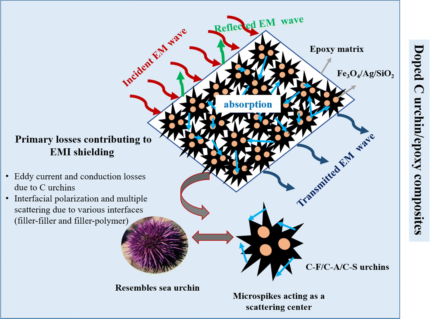 | ||
| Fig. 10 The mechanism of shielding for doped-C-urchin/epoxy-based composites. | ||
Conclusions
In summary, a facile strategy for fabricating ‘sea-urchin’-like carbon structures self-assembled from short carbon fibers is demonstrated here. When their spatial distribution is well controlled, the composites with epoxy suppressed EM radiation to a great extent. Furthermore, magnetic (Fe3O4), conducting (Ag), and dielectric (SiO2) nanoparticles were doped in turn onto the C-urchins to enhance the absorption-based shielding. Epoxy composites with C, C-F, C-A, and C-S urchins were prepared following pre- and post-curing cycles. The spatial distribution of the urchins was controlled to gain mechanistic insight into the shielding efficiency. The remarkable improvement in electrical conductivity (7.04 × 10⁻⁴ S cm−1) in the case of the composite containing closely packed C-urchins begins to suggest the presence of an interconnected conducting network that can add to the conduction and eddy current loss. All the doped C-urchins exhibited shielding effectiveness between −26 dB and −32 dB for 1 mm-thick samples in the K band; while these values are higher than the control sample, the nature of the dopant did not alter the shielding effectiveness to a large extent. In addition, absorption-dominated shielding was also seen for all doped C-urchins. Apart from improved shielding performance, the composites exhibited enhanced storage modulus values coupled with high thermal stability. In addition, the LOI values suggest that the flame-retardant properties are also slightly enhanced, manifesting that these samples can further be explored for aerospace applications. Taken together, our results offer a simple strategy for synthesizing sea-urchin-like carbon structures via the facile self-assembly of carbon fibers following refluxing in an acid medium. Also, these C-urchins are easy to disperse at length scales that are not available with conventional dispersed-flake composites.Conflicts of interest
There are no conflicts to declare.Acknowledgements
The authors would like to acknowledge financial support from DST, India, and IISc for various characterization facilities. The authors would also like to thank Jagadeshvaran PL, Devansh Sharma and Sankeerthana Avasarala for their help with performing certain characterization studies.References
- M. K. Vyas and A. Chandra, Ion–electron-conducting polymer composites: promising electromagnetic interference shielding material, ACS Appl. Mater. Interfaces, 2016, 8(28), 18450–18461 CrossRef CAS PubMed.
- Y.-D. Shi, J. Li, Y.-J. Tan, Y.-F. Chen and M. Wang, Percolation behavior of electromagnetic interference shielding in polymer/multi-walled carbon nanotube nanocomposites, Compos. Sci. Technol., 2019, 170, 70–76 CrossRef CAS.
- S. Sankaran, K. Deshmukh, M. B. Ahamed and S. K. Pasha, Recent advances in electromagnetic interference shielding properties of metal and carbon filler reinforced flexible polymer composites: a review, Composites, Part A, 2018, 114, 49–71 CrossRef CAS.
- A. Joshi and S. Datar, Carbon nanostructure composite for electromagnetic interference shielding, Pramana, 2015, 84(6), 1099–1116 CrossRef CAS.
- C. Wang, V. Murugadoss, J. Kong, Z. He, X. Mai, Q. Shao, Y. Chen, L. Guo, C. Liu and S. Angaiah, Overview of carbon nanostructures and nanocomposites for electromagnetic wave shielding, Carbon, 2018, 140, 696–733 CrossRef CAS.
- S. Mishra, P. Katti, S. Kumar and S. Bose, Macroporous epoxy-carbon fiber structures with a sacrificial 3D printed polymeric mesh suppresses electromagnetic radiation, Chem. Eng. J., 2019, 357, 384–394 CrossRef CAS.
- K. Sushmita, G. Madras and S. Bose, The journey of polycarbonate-based composites towards suppressing electromagnetic radiation, Funct. Compos. Mater., 2021, 2(1), 13 CrossRef CAS.
- K. Sushmita, G. Madras and S. Bose, Polymer Nanocomposites Containing Semiconductors as Advanced Materials for EMI Shielding, ACS Omega, 2020, 5(10), 4705–4718 CrossRef CAS PubMed.
- S. P. Pawar, P. Rzeczkowski, P. Pötschke, B. Krause and S. Bose, Does the Processing Method Resulting in Different States of an Interconnected Network of Multiwalled Carbon Nanotubes in Polymeric Blend Nanocomposites Affect EMI Shielding Properties?, ACS Omega, 2018, 3(5), 5771–5782 CrossRef CAS PubMed.
- K. Sushmita, S. Maiti and S. Bose, Multi-layered composites using polyurethane-based foams and 3D-printed structures to curb electromagnetic pollution, Mater. Adv., 2022, 3, 4578–4599 RSC.
- S. Sankaran, K. Deshmukh, M. B. Ahamed and S. K. Khadheer Pasha, Recent advances in electromagnetic interference shielding properties of metal and carbon filler reinforced flexible polymer composites: A review, Composites, Part A, 2018, 114, 49–71 CrossRef CAS.
- K. Sushmita, A. V. Menon, S. Sharma, A. C. Abhyankar, G. Madras and S. Bose, Mechanistic insight into the nature of dopant in graphene derivative influencing EMI shielding properties in hybrid polymer nanocomposites, J. Phys. Chem. C, 2019, 123(4), 2579–2590 CrossRef CAS.
- P. K. Balguri, D. G. H. Samuel and U. Thumu, A review on mechanical properties of epoxy nanocomposites, Mater. Today: Proc., 2021, 44, 346–355 CAS.
- F.-L. Jin, X. Li and S.-J. Park, Synthesis and application of epoxy resins: A review, J. Ind. Eng. Chem., 2015, 29, 1–11 CrossRef CAS.
- M. A. Boyle, C. J. Martin and J. D. Neuner, Epoxy resins, ASM handbook, 2001, 21, 78–89 Search PubMed.
- J.-P. Pascault; H. Sautereau; J. Verdu and R. J. Williams, Thermosetting polymers. Marcel DekkerNew York, 2002, vol. 477 Search PubMed.
- P. Katti, S. Bose and S. Kumar, Tailored interface resulting in improvement in mechanical properties of epoxy composites containing poly (ether ether ketone) grafted multiwall carbon nanotubes, Polymer, 2016, 102, 43–53 CrossRef CAS.
- A. Vincent, G. Ramesh and S. M. Kumar, Microwave Shielding Behaviour of Surface Treated MWCNT-epoxy Composites in I & J Band-A Note, Colloid Interface Sci. Commun., 2018, 24, 89–92 CrossRef CAS.
- J. Wu and D. Chung, Increasing the electromagnetic interference shielding effectiveness of carbon fiber polymer–matrix composite by using activated carbon fibers, Carbon, 2002, 40(3), 445–447 CrossRef CAS.
- K. Sushmita; G. Madras and S. J. F. C. M. Bose, The journey of polycarbonate-based composites towards suppressing electromagnetic radiation, 2021, 2(1), 1–38.
- R. Rohini; K. Verma and S. J. A. O. Bose, Interfacial architecture constructed using functionalized MWNT resulting in enhanced EMI shielding in epoxy/carbon fiber composites, 2018, 3(4), 3974–3982.
- Y. Bhattacharjee, D. Chatterjee and S. Bose, Core–Multishell Heterostructure with Excellent Heat Dissipation for Electromagnetic Interference Shielding, ACS Appl. Mater. Interfaces, 2018, 10(36), 30762–30773 CrossRef CAS PubMed.
- C. Liang, Z. Gu, Y. Zhang, Z. Ma, H. Qiu and J. Gu, Structural Design Strategies of Polymer Matrix Composites for Electromagnetic Interference Shielding: A Review, Nano-Micro Lett., 2021, 13(1), 181 CrossRef CAS PubMed.
- N. Bagotia, V. Choudhary and D. K. Sharma, A review on the mechanical, electrical and EMI shielding properties of carbon nanotubes and graphene reinforced polycarbonate nanocomposites, Polym. Adv. Technol., 2018, 29(6), 1547–1567 CrossRef CAS.
- G. Mittal, V. Dhand, K. Y. Rhee, S.-J. Park and W. R. Lee, A review on carbon nanotubes and graphene as fillers in reinforced polymer nanocomposites, J. Ind. Eng. Chem., 2015, 21, 11–25 CrossRef CAS.
- D. Wanasinghe, F. Aslani, G. Ma and D. Habibi, Review of polymer composites with diverse nanofillers for electromagnetic interference shielding, Nanomaterials, 2020, 10(3), 541 CrossRef CAS PubMed.
- K. Rengaswamy; D. K. Sakthivel; A. Muthukaruppan; B. Natesan; S. Venkatachalam and D. J. N. J. O. C. Kannaiyan, Electromagnetic interference (EMI) shielding performance of lightweight metal decorated carbon nanostructures dispersed in flexible polyvinylidene fluoride films, 2018, 42(15), 12945–12953.
- A. A. Eddib and D. Chung, Electric permittivity of carbon fiber, Carbon, 2019, 143, 475–480 CrossRef CAS.
- T. K. Das, P. Ghosh and N. C. Das, Preparation, development, outcomes, and application versatility of carbon fiber-based polymer composites: a review, Adv. Compos. Hybrid Mater., 2019, 1–20 Search PubMed.
- T. Xiao, J. Kuang, P. Sun, X. Hou, Q. Wang, P. Jiang and W. Cao, Rapid microwave synthesis of coaxial SiC/carbon fibre (SiC/CF) with improved oxidation resistance and wettability, Ceram. Int., 2019, 45(2), 2432–2438 CrossRef CAS.
- S. Chand, Review carbon fibers for composites, J. Mater. Sci., 2000, 35(6), 1303–1313 CrossRef CAS.
- T. Gayathri, N. Kavitha, A. Chandramohan, D. Roy and K. J. M. T. P. Dinakaran, Mesoporous zirconia nanostructures embedded Polyvinyledine difluoride conducting films for EMI shielding applications, 2022, 59, 534–539.
- K. Dinakaran, K. Narayanasamy, S. Theerthagiri, P. Peethambaram, S. Krishnan and D. J. I. J. O. P. A. Roy, Characterization, Microwave absorption and dielectric behavior of lead sulfide–graphene composite nanostructure embedded polyvinylidinedilfuoride thin films, 2022, 1–12.
- K. Rengaswamy; V. K. Asapu; A. Muthukaruppan; D. K. Sakthivel; S. Venkatachalam and D. J. P. F. A. T. Kannaiyan, Enhanced shielding of electromagnetic radiations with flexible, light-weight, and conductive Ag-Cu/MWCNT/rGO architected PVDF nanocomposite films. 2021, 32 (9), 3759–3769.
- M. Gholampoor; F. Movassagh-Alanagh and H. J. S. S. S. Salimkhani, Fabrication of nano-Fe3O4 3D structure on carbon fibers as a microwave absorber and EMI shielding composite by modified EPD method. 2017, 64, 51–61.
- B. Cheng, J. Wang, F. Zhang and S. J. P. B. Qi, Preparation of silver/carbon fiber/polyaniline microwave absorption composite and its application in epoxy resin, 2018, 75(1), 381–393 CAS.
- F. Movassagh-Alanagh, S. Jalilian, R. Shemshadi and A. J. S. M. Kavianpour, Fabrication of microwave absorbing Fe3O4/MWCNTs@ CFs nanocomposite by means of an electrophoretic co-deposition process, 2019, 250, 20–30 CAS.
- Y. Wei, J. Yue, X.-Z. Tang, Z. Du and X. Huang, Enhanced magnetic and microwave absorption properties of FeCo-SiO2 nanogranular film functionalized carbon fibers fabricated with the radio frequency magnetron method, Appl. Surf. Sci., 2018, 428, 296–303 CrossRef CAS.
- B. Zhao, G. Shao, B. Fan, W. Zhao and R. Zhang, Investigation of the Electromagnetic Absorption Properties of Ni@TiO2 and Ni@SiO2 Composite Microspheres with Core-Shell Structure, Phys. Chem. Chem. Phys., 2015, 17, 2531 RSC.
- Y. Ren, C. Zhu, S. Zhang, C. Li, Y. Chen, P. Gao, P. Yang and Q. Ouyang, Three-Dimensional SiO2@Fe3O4 Core/Shell Nanorod Array/Graphene Architecture: Synthesis and Electromagnetic Absorption Properties, Nanoscale, 2013, 5, 12296 RSC.
- F. Movassagh-Alanagh, A. Bordbar-Khiabani and A. Ahangari-Asl, Three-phase PANI@ nano-Fe3O4@ CFs heterostructure: Fabrication, characterization and investigation of microwave absorption and EMI shielding of PANI@ nano-Fe3O4@ CFs/epoxy hybrid composite, Compos. Sci. Technol., 2017, 150, 65–78 CrossRef CAS.
- Y. Liu, Z. Chen, W. Xie, S. Song, Y. Zhang and L. Dong, In-situ Growth and Graphitization Synthesis of Porous Fe3O4/Carbon Fiber Composites Derived from Biomass as Lightweight Microwave Absorber, ACS Sustainable Chem. Eng., 2019, 7(5), 5318–5328 CrossRef CAS.
- A. V. Menon, G. Madras and S. Bose, Ultrafast Self-Healable Interfaces in Polyurethane Nanocomposites Designed Using Diels–Alder “Click” as an Efficient Microwave Absorber, ACS Omega, 2018, 3(1), 1137–1146 CrossRef CAS PubMed.
- S. P. Pawar, S. Kumar, S. Jain, M. Gandi, K. Chatterjee and S. J. N. Bose, Synergistic interactions between silver decorated graphene and carbon nanotubes yield flexible composites to attenuate electromagnetic radiation, 2016, 28(2), 025201.
- Y. Bhattacharjee, D. Chatterjee and S. J. A. A. M. Bose, Interfaces, Core–multishell heterostructure with excellent heat dissipation for electromagnetic interference shielding, 2018, 10(36), 30762–30773.
- R. Rohini and S. Bose, Tailored interface and enhanced elastic modulus in epoxy-based composites in presence of branched poly (ethyleneimine) grafted multiwall carbon nanotubes, Phys. Chem. Chem. Phys., 2015, 17(12), 7907–7913 RSC.
- P. K. Samantaray, S. Baloda, G. Madras and S. Bose, Interlocked Dithi-Magnetospheres–Decorated MoS2 Nanosheets as Molecular Sieves and Traps for Heavy Metal Ions, Adv. Sustainable Syst., 2019, 1800153 CrossRef.
- A. Shalaby, V. Yaneva, A. Staneva, L. Aleksandrov, R. Iordanova and Y. J. N. N. Dimitriev, Thermal stability of RGO and RGO/SiO2 nanocomposite prepared by sol-gel technique, 2014, 14, 120.
- T. Zhang, Y. Song, Y. Zhao, B. J. C. Zhang, S. A. Physicochemical and E. Aspects, Effect of hybrid sizing with nano-SiO2 on the interfacial adhesion of carbon fibers/nylon 6 composites, 2018, 553, 125–133 CAS.
- A. Chaudhary, R. Kumar, S. Teotia, S. Dhawan, S. R. Dhakate and S. Kumari, Integration of MCMBs/MWCNTs with Fe 3 O 4 in a flexible and light weight composite paper for promising EMI shielding applications, J. Mater. Chem. C, 2017, 5(2), 322–332 RSC.
- P. Katti, K. Kundan, S. Kumar and S. Bose, Poly (ether ether ketone)-Grafted Graphene Oxide “Interconnects” Enhance Mechanical, Dynamic Mechanical, and Flame-Retardant Properties in Epoxy Laminates, ACS Omega, 2018, 3(12), 17487–17495 CrossRef CAS PubMed.
- S. P. Pawar, S. Biswas, G. P. Kar and S. Bose, High frequency millimetre wave absorbers derived from polymeric nanocomposites, Polymer, 2016, 84, 398–419 CrossRef CAS.
- H. Nallabothula, Y. Bhattacharjee, L. Samantara and S. Bose, Processing-Mediated Different States of Dispersion of Multiwalled Carbon Nanotubes in PDMS Nanocomposites Influence EMI Shielding Performance, ACS Omega, 2019, 4(1), 1781–1790 CrossRef CAS PubMed.
- R. Chippendale and I. O. Golosnoy, In Percolation effects in electrical conductivity of carbon fibre composites, IET 8th International Conference on Computation in Electromagnetics (CEM 2011), IET, 2011, pp. 1–2.
- Y. Xi, Y. Bin, C. Chiang and M. Matsuo, Dielectric effects on positive temperature coefficient composites of polyethylene and short carbon fibers, Carbon, 2007, 45(6), 1302–1309 CrossRef CAS.
- M. H. Al-Saleh and U. Sundararaj, Electromagnetic interference shielding mechanisms of CNT/polymer composites, Carbon, 2009, 47(7), 1738–1746 CrossRef CAS.
- H. Hekmatara, M. Seifi, K. Forooraghi and S. J. P. C. C. P. Mirzaee, Synthesis and microwave absorption characterization of SiO 2 coated Fe 3 O 4–MWCNT composites, 2014, 16(43), 24069–24075 CAS.
- N. Li, Y. Huang, F. Du, X. He, X. Lin, H. Gao, Y. Ma, F. Li, Y. Chen and P. C. Eklund, Electromagnetic interference (EMI) shielding of single-walled carbon nanotube epoxy composites, Nano Lett., 2006, 6(6), 1141–1145 CrossRef CAS PubMed.
- A. D. S. Gomes, New polymers for special applications. BoD–Books on Demand, 2012.
- P. Saini, V. Choudhary, B. Singh, R. Mathur and S. Dhawan, Polyaniline–MWCNT nanocomposites for microwave absorption and EMI shielding, Mater. Chem. Phys., 2009, 113(2-3), 919–926 CrossRef CAS.
- A. V. Menon, G. Madras and S. Bose, Phase specific dispersion of functional nanoparticles in soft nanocomposites resulting in enhanced electromagnetic screening ability dominated by absorption, Phys. Chem. Chem. Phys., 2017, 19(1), 467–479 RSC.
- A. V. Menon, G. Madras and S. Bose, Magnetic Alloy-MWNT Heterostructure as Efficient Electromagnetic Wave Suppressors in Soft Nanocomposites, ChemistrySelect, 2017, 2(26), 7831–7844 CrossRef CAS.
- C. Wang, X. Han, X. Zhang, S. Hu, T. Zhang, J. Wang, Y. Du, X. Wang and P. J. T. J. O. P. C. C. Xu, Controlled synthesis and morphology-dependent electromagnetic properties of hierarchical cobalt assemblies, 2010, 114(35), 14826–14830 CAS.
- C. Wang, X. Han, P. Xu, J. Wang, Y. Du, X. Wang, W. Qin and T. J. T. J. O. P. C. C. Zhang, Controlled synthesis of hierarchical nickel and morphology-dependent electromagnetic properties, 2010, 114(7), 3196–3203.
Footnote |
| † Electronic supplementary information (ESI) available. See DOI: https://doi.org/10.1039/d2ma00715k |
| This journal is © The Royal Society of Chemistry 2022 |