 Open Access Article
Creative Commons Attribution 3.0 Unported Licence
A critical review: the impact of electrical poling on the longitudinal piezoelectric strain coefficient
Sanskruti Smaranika
Dani
a,
Alekhika
Tripathy
a,
Nagamalleswara Rao
Alluri
bc,
Saravanakumar
Balasubramaniam
a and
Ananthakumar
Ramadoss
 *ad
*ad
aLaboratory for Advanced Research in Polymeric Materials (LARPM), School for Advanced Research in Petrochemicals (SARP), Central Institute of Petrochemicals Engineering & Technology (CIPET), Patia, Bhubaneswar-751024, Odisha, India. E-mail: ananth@larpm.in; Fax: +91-674-2740463; Tel: +91-674-2740173
bMaterials Research and Technology Department, Luxembourg Institute of Science and Technology, 41 rue du Brill, L-4422 Belvaux, Luxembourg
cInter-Institutional Research Group Uni.lu-LIST on Ferroic Materials, 41 rue du Brill, L-4422 Belvaux, Luxembourg
dSchool for Advanced Research in Polymers: Advanced Research School for Technology & Product Simulation, Central Institute of Petrochemicals Engineering & Technology, Guindy, Chennai-600032, India
First published on 5th September 2022
Abstract
Piezoelectric materials play an essential role in the advancement of micro- and nanoelectronics equipment. The piezoelectric properties of the materials rely upon the degree of polarization that results from the poling mechanism. The present study put forward the improvement of piezoelectric performance by optimizing the poling parameters in piezoelectric materials. Microstructural optimization of flexible piezoelectric-based material is one possible technique to improve the electrical responses of the piezoelectric nanogenerator. In particular, the correlation between the poling conditions and the longitudinal figure of merit (d33) of various materials (lead-based, lead-free and polymers and their composites) provides an effective analysis to supplement the available literature. This report examines the latest research progress in different poling techniques and their consequences for achieving the required beta-phase of a polyvinylidene fluoride (PVDF) film with a higher electrical output. Finally, novel poling techniques, the current challenges, and prospects are highlighted and critically discussed, currently which is relatively untouched research field for the scientific community. We believe that this review affords systematic guidelines for poling techniques that can significantly contribute to subsequent piezoelectric nanogenerator (PENG) research.
1. Introduction
With the growing utilization of high-performance piezoelectric materials, researchers are continuously trying to improve device activity in a variety of ways such as changing the piezoelectric properties,1,2 adjusting the device configuration,3 and utilizing electrical networks for energy storage and harvesting.4,5 In addition, scientists have continued to improve the piezoelectric performance by modifying the chemical configuration, crystallographic direction, and domain engineering.6 Not withstanding all of the techniques, optimization of the poling parameters7,8 is one of the most beneficial and reasonable methods from a practical application perspective. Crystalline phase of material with noncentrosymmetric property, poling procedures are thought to be strongly related to the piezoelectric, ferroelectric effects. Moreover, enhancement of the piezoelectric properties, primarily the longitudinal piezoelectric strain coefficient (d33), by adjusting the poling parameters is a vast area of interest.9,10 Perovskite single crystals (piezoelectric/ferroelectric) have no polarization tendency until the domain alignment is switched through the poling technique. The influence of ferroelectric poling on the material response is initially explored to investigate the d33 rate of soft lead zirconate titanate (PZT), via optimizing the poling conditions.The most feasible way to achieve stable polarization is to minimize exposure of the polar dielectric near to the curie temperature (Tc), poled greater than the coercive field. For few compositions (PLZT, (Bi0.5Na0.5)TiO3-BaTiO3, P4bm phase), the poling field below the coercive field.11,12,29 This is because excessive poling (strong field) for a long duration tends to over-pole the sample. This may cause electrical breakdown and physical imperfections like cracks and pores in the specimen, resulting in loss of the electrical characteristics. Mechanical stress and electric fields facilitate the ferroelastic and ferroelectric transition, respectively, which successfully pole the systems at low electric fields with minimal built-in offset polarisation for electromechanical poling.13 Long-term poling can result in a biased electric field and offset polarisation in samples, owing to the entrapment of mobile charge carriers across the grains and at grain–grain interfaces.14
To generate piezoelectric behaviour in piezoelectric materials, the poling procedure is very important.15 In a normal situation, the piezoelectric material is formed of tiny electric dipoles with random arrangements, resulting in a total dipole moment of zero. By applying mechanical pressure, structural deformation occurs, and the material will exhibit very little polarization and thus minimal piezoelectric output. For a better performance of the piezoelectric material-based devices, dipoles need to be aligned in a particular field direction. The process of inducing dipoles to align in a specific direction is recognized as the poling process. Domain switching or polarization is achieved using different poling techniques, mainly through the application of a strong electric field, such as in direct-current electrical poling (DC poling), alternating-current poling (AC poling), or corona-discharge methods.16,17 During the poling process, domain alignment takes place in the field direction, resulting in a huge net polarisation and the capture of mobile free charge carriers (oxygen vacancies). This results in a more stable structure with fewer local heterogeneities. At the end of the poling process, cations may serve as defect centres for the reduction of trapped free charge carriers, which contributes to a well-saturated polarization–electric field (P–E) loop. The optimal poling parameters of various piezoelectric materials are thoroughly investigated by the researchers across the globe and used as a powerful, essential tool for enlightening the intrinsic piezoelectric behaviour of material.18 For instance, a higher d33 value of ∼630 pC N−1 is obtained in barium zirconium titanate–barium calcium titanate (0.5Ba(Zr0.2Ti0.8)O3–0.5(Ba0.7Ca0.3)TiO3) ceramics via optimizing the poling-condition states like the poling field and temperature.7 In addition, the d33 value of potassium sodium niobate–lithium niobate (0.93(K0.5Na0.5)NbO3–0.07LiNbO3) ceramics was improved from 210 to 274 pC N−1 through the selection of a preferable poling temperature8 (nearer to the phase-transition temperature). By summarizing the above facts and theory, it can be resolved that targeting the optimum poling conditions is the most successful approach for enhancing the piezoelectricity.
The fundamental mechanism of piezoelectricity is the transformation of mechanical strain into electrical energy which is interconnected through piezoelectric strain coefficients. The effectiveness and efficiency of piezoelectric-material-based devices are largely dependent on the different piezoelectric strain coefficients: d15, d31, and d33, which are the shear, transverse, and longitudinal piezoelectric strain coefficients, respectively. The majority of investigations have found that the mechanism of action for piezoelectric materials is the transverse (d31) mode.19–21 In contrast to the transverse mode, other piezoelectric strain coefficients such as the shear (d15) and longitudinal (d33) coefficients have been investigated to improve the output performance. A detailed study has been performed by Caliò et al.22 to observe the influence of these three operating modes on the device performance basis. It has been proved that the poling direction in d33 and d31 is the same, but the strain is generated in two separate directions. On the other hand, in d15, the poling process can be performed across the length of the element. Due to this variation in the piezoelectric stain coefficient values, noticeable changes are observed in the output values during application.23,24 Based on the functionality of these three modes (d31, d33 and d15) a comparative study has been carried out by the researchers.23 Kiran et al. found that the maximum values of the shear, transverse, and longitudinal piezoelectric strain coefficients for polycrystalline materials based on theoretical models were 407, −320, and 697 pC N−1, respectively.25–28 However, the experimental values of the longitudinal coefficient are greater than those of the theoretical model.29 In general, the d33 value is double that of the d31 value; therefore, in d33 mode the device generates a higher performance. On the other hand, electrode distance constraints limit the output voltage of the device in d31 mode. Contrary to this, in d33 mode, the sample displays an inferior capacitance, and the voltage output may be regulated by modifying the electrode arrangement. Whereas the higher shear strain coefficient value is observed but quite typical to achieve it.30,31 Abundant research has been carried out based on fabrication and configuration procedures for device performance in the d33 mode.32,33 In particular, for the commercial poling process, there is a primary concern with d33 in the view of the device performance.23 A comprehensive examination of the impact of the poling parameters on the d33 values could enable the more accurate adjustment of d33 and other poling-influenced features.
This review covers the importance of the poling process and the theory behind it, as well as different kinds of poling technique, discusses the various factors that affect the poling process, analyses the variation of d33 values for both PZT-based and lead-free barium titanate (BT), bismuth sodium titanate (BNT), and potassium sodium niobate (KNN) based piezoelectric materials, polymers and composites for the poling process, and the increased values of d33 due to different poling conditions, which in turn improve the yield of piezoelectric nanogenerators (PENGs). The purpose of this study is to gain a deeper comprehension of the poling process and its impact on the electrical properties for creating superior engineered materials. The electromechanical behaviour of the material dramatically changes in accordance with the poling circumstances. These findings put forward new ways of developing materials and technologies that have a greater capacity, performance, and lower deterioration due to electrical fields and mechanical stress. The possible microstructural roots of this type of behaviour are also examined.
2. Piezoelectricity and polarization process
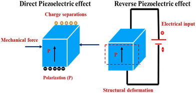
Piezoelectricity was initially revealed by the Curie brothers, Jacques and Pierre, in the year 1880, by experimenting on natural crystal-like quartz.34 The prefix ‘piezo’ is taken from Greek name ‘piezein’, which means to press, so piezoelectricity is the process of generating electric charge via the application of pressure onto such materials. A non-centrosymmetric material has no points of inversion, and this is the main requirement of a piezoelectric material. So, the phenomenon of the piezoelectric effect is shown only by non-centrosymmetric materials. These materials have an outstanding beauty because of their inherent properties of electric polarization, which occur via the application of applied stress, and, simultaneously, they can also generate an induced strain via the application of an electric field, which is known as reverse piezoelectricity.35 Direct piezoelectricity is used in sensing devices, whereas the reverse piezoelectric effect can be employed in actuators. Fig. 1 shows the mechanisms of the direct and reverse piezoelectric effects.These two effects (the direct and reverse piezoelectric effects) are expressed in terms of two equations as given below:36
| Si = SEijTj + dkiEk | (1) |
| Di = εTikEk + dijTj | (2) |
In eqn (1) and (2), the subscripts i, j, and k36 denote the three-dimensional magnitudes. T and S are the tensors of stress and strain, respectively, that are generated by electromechanical effects. E and D represent the applied electric field and the electric displacement vector, respectively. The parameter d is the piezoelectric strain coefficient; SE is the elastic compliance estimate at a fixed electric field (E) and εT is the dielectric constant or relative permittivity.36 The coefficients of piezoelectricity are represented with double subscripts (for example, d33), where the 1st subscript denotes the produced charge or the electrical field of the supplied voltage, and the 2nd subscript denotes the strain/mechanical stress direction.
Ferroelectrics belong to a subclass of piezoelectric materials that display spontaneous polarization because of their inherent non-centrosymmetric configuration. Permanent electric dipoles are responsible for spontaneous polarization in ferroelectric materials. These materials are included in the class of polar piezoelectrics, for example, PVDF, polarized PZT, polyvinylidene fluoride-trifluoroethylene (P(VDF-TrFE)), barium titanate (BaTiO3), etc. Thus, all ferroelectrics are piezoelectric, although the reverse is incorrect.
Some examples of piezoelectric materials are provided here:
• Naturally available piezoelectric materials are cellulose, human bone, tendon, collagen, etc.
• Naturally occurring piezoelectric crystals are Rochelle's salt (NaKC4H4O6·4H2O), topaz, quartz (SiO2), etc.
• Ceramics, such as potassium niobate (KNbO3), BaTiO3, PZT, bismuth ferrite (BiFeO3), etc.
• Polymers, such as cellulose and derivatives, polylactic acid (PLA), and PVDF.
• Inorganic nanoparticles–polymer composites, such as polyimides–PZT, cellulose–BaTiO3, polyvinylidene fluoride–zinc oxide (PVDF–ZnO), etc.
3. Effect of poling and piezoelectric strain coefficients
Piezoelectric polycrystalline materials have anisotropic properties, so their electromechanical properties differ along the direction of excitation. These materials are composed of tiny crystallites, and each crystallite again consists of microscopic regions that have dipole orientations in the same direction, called ‘domains’, and they are typically created to reduce the system's free energy. A domain wall is a boundary between two domains. But each domain in the crystallite has different arrangements of dipoles from each other. So, the overall effect of randomly oriented dipoles cancels out, and the material is depolarized. For polarization of a material, it is therefore important to arrange the dipoles more or less in a particular path. This is achieved via the poling procedure, and the track along which all the dipoles are aligned is known as the poling direction. For initiation of the poling process for any piezoelectric material, a higher electric field is essential along with a suitable temperature for alignment of the randomly oriented dipoles that creates permanent polarization. Fig. 2A shows the randomly oriented dipoles before poling, the aligned dipoles after poling and the nearly aligned dipoles after the field has been removed. Once the material is polarized, it cannot be depolarized until a reverse field is applied. After the poling process, the dipoles are nearly aligned. At zero field, most of the dipoles conserve their aligned configuration, so the material is permanently polarized, and this state of a nearly aligned process is called remanent polarization (Pr).37Fig. 2B describes the P–E hysteresis loop due to the polarization of ferroelectric materials. It has been observed that a lower value of remanent polarization demands an improved energy-storage capacity.38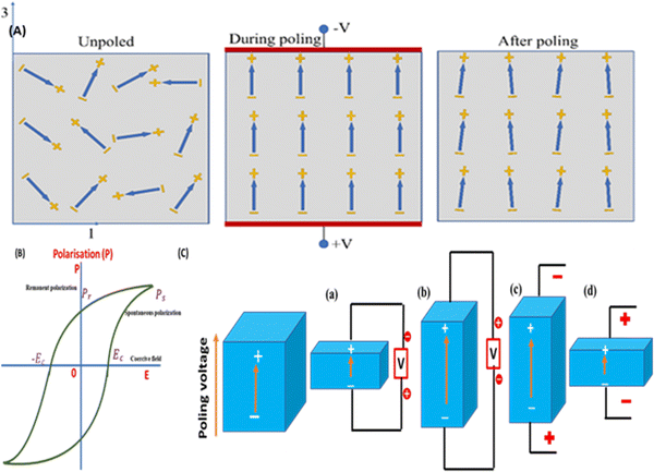 | ||
| Fig. 2 (A) Domain alignment mechanisms before, during, and after the poling process; reproduced with consent from ref. 39. Copyright 2021, Springer Nature. (B) Polarisation–electric field hysteresis curve, and (C) piezoelectric material work as a sensor and actuator in various fields. | ||
During the polarization process of a material, deformation takes place permanently and the deformation (elongation or compression) depends on the poling direction. Mechanical stress (tension or compression) is responsible for the change in dipole positions in the piezoelectric materials that leads to generation of positive (+ve) and negative (−ve) surface charges across the top or bottom of the material. Fig. 2C explains the direct and converse piezoelectric effect. If stress is applied along the poling-voltage direction, compression occurs and the sample becomes broader (towards the diameter) creating a voltage of equal polarity to that of the poling voltage (Fig. 2C(a)). On the other hand, elongation along the poling-voltage direction generates an opposite polarity voltage compared with the poling voltage (Fig. 2C(b)). This is the direct piezoelectric effect, which converts mechanical stress into electrical energy, and the device can be used as a sensor.40
The sample extends lengthwise and shrinks towards its diameter if the applied voltage direction is along its poling direction (Fig. 2C(c)). On the other hand, if an opposite polarity voltage is applied in the poling direction, then the material will be deformed, becoming shorter and wider (Fig. 2C(d)). When the device is exposed to an alternating voltage, then expansion and compression take place in the material periodically with reference to the applied voltage frequency. In this mode the piezoelectric specimen acts as an actuator,41i.e., the electrical energy is transferred into mechanical energy. Thus, the amount of voltage or stress produced in a sensor or actuator device is directly proportional to the intrinsic properties of the piezoelectric material and the direction of the applied force/voltage during the poling process. The initial polarisation will be damaged if too high a voltage is applied in the depoling direction (partially or fully depolarized). Alternatively, the electric dipoles could be partially or entirely flipped 180°, triggering the specimen to depole in the opposite direction. The coercive field is the highest depoling field that a material is able to endure before depolarization.
Under operational conditions, piezoelectric materials are adjusted in such a manner that anyone piezoelectric coefficient (d15/d31/d33) will dominate the yield of the device. As mentioned in the Introduction, the d33 mode (stress and voltage act in the ‘3’ direction) is practically more favourable compared with other modes d31 and d15, indicating that the poling orientation is always in the 3 direction. Materials that are easily distorted to create greater strains and have substantial electromechanical coupling coefficients are ideal for energy-harvesting applications. Furthermore, energy-harvesting devices based on human mechanical movement require low-frequency operation conditions (∼1 Hz), like breathing, walking or other body movements. In this process, the elastic energy (W), which is conserved in the material, can be denoted by the maximal stress or strain:36
 | (3) |
 | (4) |
 | (5) |
For energy-harvesting applications, the piezoelectric material will be chosen in such a manner that the material exhibits the highest d33 constant, which will impart the maximum energy-conversion efficiency.
4. Poling and ferroelectric hysteresis loop
Ferroelectric domain-wall switching via the poling process is the most important phenomenon in ferroelectrics, which occurs because of the application of an electric field E.42,43 This domain-wall switching is responsible for the formation of the ferroelectric hysteresis loop shown in Fig. 3A(a). In ferroelectric materials when a small amount of AC electric field is applied, the polarization (P) rises in proportion to E as per the relation Pi = χijEj, which corresponds to the AB section of the loop. In this section, E is not strong enough for the increment of the AB part. A further increase in E forces a switch of the domains in the applied E direction, and as a result a sharp increase in polarization occurs (BC segment). Finally, at point C, all domains are aligned and the ferroelectric reverts to a linear dielectric, as represented by the segment CD. When the field is weakened, some of the domains are switched back, but some polarization still exists in the absence of E (PR, i.e., the remanent polarization region). In order to regain the depolarization state, a reverse E is needed (point F). For zero-polarization, E must be reversed at point F. An additional rise of the reverse E leads to a new arrangement of the dipoles, leading to the saturation region (point G). To complete the cycle, E has to be reversed and diminished. The coercive electric field, abbreviated as Ec, is the field required to achieve a zero-polarization state. For most ferroelectric ceramics and crystals, the magnitude of Ec is in the range of 10–100 kV cm−1. For an ideal hysteresis loop (P–E), both the positive–negative coercive field and the remanent polarization must be identical.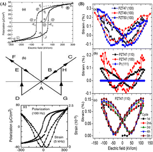 | ||
| Fig. 3 (A) Polarization process of ferroelectric materials: (a) schematic of the polarization–electric field (P–E) hysteresis loop; and (b) and (c) represent the ferroelectric strain–electric field (S–E) butterfly hysteresis loop of the Pb(Zr0.45Ti0.55)O3 film; reproduced with the permission from.46 Copyright, 2005 Elsevier. (B) S–E butterfly loop of PZT (PbZr1−xTixO3) thin films for different doping concentrations x = 0.47, 0.49, and 0.50 with different plane orientations: (a) PZT47 (100), PZT49(100), PZT50(100), (b) PZT47(110), PZT47(100), Pt (111), and (c) PZT47 (110); reproduced with permission from ref. 47. Copyright 2017, AIP publisher. | ||
In contrast to the P–E loop, domain switching by polarization leads to the strain–electric field (S–E) hysteresis loop, which is also known as the butterfly loop due to its butterfly-like configuration. This S–E loop is mainly created because of the converse piezo effect, domain switching, and domain-wall movement. Fig. 3A(b, c) represents the symmetric diagram of the S–E butterfly loop. In the S–E loop at point A, the induced strain is zero when the applied electric field is zero. By applying a strong E along the spontaneous polarization direction, the material expands due to the generation of stress and traces the strain path ABC as per the equation:44,45
| Sjk = dijkEi | (6) |
Cornelius et al. explained the polarization response of the P–E hysteresis loop, and the S–E butterfly loop of self-poled PZT thin films deposited on Pt/TiO2/SiO2/Si substrates.47d33 was obtained from the butterfly curves as shown in Fig. 3(B). It was observed that the effective piezoelectric strain coefficient (d33,eff) varied with the substrate used for the same field (E = ±119 kV cm−1). For the positive field E+ = 119 kV cm−1, the values of d33 are 137, 180, and 140 pm V−1, and for the negative field (−119 kV cm−1) the d33 values are 164, 189, and 223 pm V−1 along the100 direction for the PZT (PbZr1−xTixO3) composition (x = 0.47, 0.49, and 0.50), respectively.
5. Poling techniques
There are different methods of poling, such as (i) DC electrode poling, (ii) corona discharge poling, and (iii) AC electrode poling. The most used poling processes are DC electrode poling and corona discharge poling, and AC electrode poling has been introduced recently. In the following section, we elaborately discuss each poling process, its merits and its demerits.5.1. DC electrode poling
Electrode poling48 is a direct current poling method. It is a relatively simple method and is older than other methods (such as corona poling and AC poling). Electrospinning49 or sputtering deposition50 methods are used to deposit the top and bottom metal electrodes on piezoelectric material. Alternatively, the piezoelectric sample is mechanically sandwiched between the top and bottom copper (or aluminium) foil/tape electrodes or brush coating of conductive silver paste on top and bottom of piezoelectric sample. A very close contact between the electrodes and the piezoelectric material is needed to enhance the polarization of the diploes. For thermal excitation, the material should be heated using a hot plate. Temperature is the primary factor in the poling process, and a preferable temperature will be very effective for enhancing the piezoelectric strain coefficient (d33). Electrode poling is commonly carried out using an isolating medium, such as a silicone oil bath/inert atmosphere, to insulate the material from excessive electric discharge, which also helps to maintain a constant temperature. So, the initial step is to immerse the electrodes in the oil bath and gradually increase the temperature near to the Curie point of the material as specified; this is because above the Curie temperature the activity of the material will be degraded (d33 value decreases). Furthermore, the DC voltage is gradually increased until the electric field (5–1000 kV cm−1)48,51–53 across the sample matches the indicated saturation polarisation values. This voltage is maintained for a brief time period. The sample is then cooled to room temperature slowly under a constant E, and the high voltage source is finally turned off. Subsequently, the d33 value of the poled sample is analysed using a piezometer. Fig. 4(a) shows the DC electrode poling technique of the sample.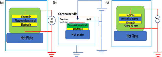 | ||
| Fig. 4 Poling techniques: (a) Direct-current electrode poling process. (b) Corona discharge poling process. (c) Alternating-current electrode poling process. | ||
5.2. Corona discharge poling
The traditional DC technique for poling piezoelectric samples has several drawbacks. In this procedure, the electrodes must be coated on the top and bottom portion of the specimen, and poling is applicable for tiny samples. Corona poling requires metallization on a single side of the piezoelectric material and does not need a further vacuum environment. However, the corona discharge uses the breakdown of dry air or an inert gas48,51,54 to polarise the piezoelectric material, which means that it is far more complicated than electrode poling. Localized breakdown occurs at frail points, such as pinholes, which short-circuits the electrodes, preventing additional polarization. This process has been used to manufacture large-area film samples with great success.55 In the corona poling process, charges from the corona point (a needle) will be dispersed over the bare part of the sample surface (which is not covered by the electrode) producing an electric field between the sample surfaces. An electrostatic kilovoltmeter55 or a comparison method56 can be used to assess the sample's surface potential. There is no short-circuiting of the sample in the weaker regions because there are no electrodes. As a result, it is a more improved technique. The corona discharge approach could be used to pole large-area samples and integrate them into a continuous process for industrial production.Unlike electrode poling, the corona poling process is an indirect method of poling. Fig. 4(b) illustrates the corona discharge process. In corona poling, a pin-point conduction pointer (a needle) is exposed with a higher voltage ∼8–20 kV, ionizing the gas molecules near the tip. A metallic grid that is operated at a lower voltage of 0.2–3 kV and is present just below the needle is responsible for controlling the accelerated ionized particles that move towards the piezoelectric material. The number of dropped charges on the material surface is controlled via the grid location and the applied voltage through control of the supplied E. An electrode covers the bottom surface of the material, which is in touch with a hot substrate (hot plate) to supply heat for controlling the poling process.57 For all materials, the poling temperature should not exceed 300 °C for both methods (electrode poling and corona discharge).
5.3. Alternating current poling (ACP)
Yamashita et al.58,59,74,75 recently developed an ACP approach, demonstrating a cost-effective and time-saving domain-engineering scheme that attracted the scientific community. Because of its excellent efficiency, minimal cost, and time savings, ACP technology is becoming increasingly popular. The dielectric and piezoelectric characteristics of ferroelectric crystals are thought to be intimately connected to the ferroelectric phase and the poling direction.60 As a result, the effect of ACP may also be related to the poling direction and crystal symmetry. Furthermore, the improvement of piezoelectric characteristics after ACP is attributed to the change in domain arrangement. The impact of the domain-wall motion is typically regarded as an external contribution, which is unknown.AC poling is similar to DC electrode poling, with the only difference being that in DC poling a high direct voltage is applied, and in ACP a high alternating voltage is applied. ACP also leads to full polarization of the sample.61 Like the DC electrode poling method, the sample is placed between the electrodes inside an oil bath and a very high alternating voltage is supplied. After poling, the material is cooled, and d33 and another required parameter measurement are performed. In Fig. 4(c), a schematic of the AC electrode poling technique of the active material is represented.
It has been claimed that ACP is a far more appropriate method than DC poling. ACP has resulted in the enhanced piezoelectric activity of PMN–PT crystals and increased d33 values of up to 40%.59 However, the processes of the ACP technique are not well understood. Many scientists have proposed theories about the principles of ACP. Chang et al. proposed that the monoclinic phase (MP) accounts for the better piezoelectric performance.62 Luo et al. employed domain enlargement theory to analyse the domain structure alteration process.63 Qiu et al. proposed a novel theory in which the piezoelectric performance is improved by polar nano regions (PNRs) or a localized configuration.64 He et al. later examined the Pb[(Mg1/3Nb2/3)0.52(Yb1/2Nb1/2)0.15Ti0.33]O3 (PMN-PYbN-PT) structure and concluded that an extremely organized domain configuration is responsible for the excellent piezoelectricity.65 According to Qiu et al., the improvement in the piezoelectric capability is connected to the decline of the 71° domain wall.66
Luo et al. investigated the effect of high-temperature ACP on PIMN-0.30PT single crystals (prepared using the continuous-feeding Bridgman (CF BM) process with different temperatures and poling fields ranging from 70 to 130 °C and 2 to 6 kVrms cm−1) and observed exceptional higher d33 values of 7000 pC N−1 (29% greater than with DC poling) along with higher free dielectric permittivity (ε33T/ε0) and coupling factor (k33) values under the optimized poling conditions of 90 °C at 4 kVrms cm−1, respectively.67 Recently, Su et al. made a comparative study of square- and sine-waveform ACP of (001) oriented PMN-28 PT single crystals at 80 °C and at high voltage (5 kVrms cm−1) to solve the problem of spurious-mode vibrations (SMV) and to obtain the optimized poling conditions for enhanced piezoelectricity and restoration of the altered electrical impedance spectrum that was realized due to the ACP process in single crystals.68 The majority of ACP investigations are based on relaxor PT materials with a lower value of Ec, such as lead magnesium niobate–lead titanate-based materials (PMN–PT and PIN–PMN–PT), with little attention given to relaxor PT crystals with higher Tc and Ec characteristics.
In addition to the above poling techniques (DC electro poling, corona discharge and ACP) discussed earlier, polarization may be achieved using alternative methods,69 for example, other processes such as electron beam poling,70 mechanical drawing,71 electrospinning,72 and additive manufacturing.73 However, these are not effective on a large scale and for all piezoelectric materials.74,75 Liu et al. describe different poling methods for the scalable manufacturing of the highly efficient electroactive PVDF polymer74,76 as well as their merits and downsides.
6. Factors affecting the poling process
Domains arise for lowering the electrostatic energy of the depoling field when a piezoelectric material transforms from the para- to the ferro-electric state.45,77,78 Domain aligning occurs in polycrystalline ceramics through applying a high DC field (the poling field strength) that must be higher79 than Ec for a particular temperature range (the poling temperature). Higher temperatures accelerate the domain movement, resulting in the realignment of spontaneous polarisation within every grain, leading to a net polarization in the same poled direction. As a result, one of the most essential variables in increasing the piezoelectric characteristics is the poling process (poling conditions).The degree of alignment of the dipoles depends on several factors in the poling process, such as the uniformity and value of the applied temperature, the field strength, the dimensions of the materials, the time duration and consistency of the applied electric field as well as its frequency,61,80 the manufacturing procedure, the filler content or doping concentration, the porosity and the percentage of impurities.57,81 During the poling process, mechanical stress also has an impact on the domain-wall movement.57,82 Among the above-mentioned numerous factors, the applied field strength, operating temperature and poling time are the most effective parameters that will affect the piezoelectric strain coefficient value. So, the primary focus is on these three parameters, which will affect the d33 value and device application based on its performance. Some examples are discussed below.
Kumar et al.29 investigated the optimum poling conditions and their influence on d33 and the electromechanical coupling factor (kp) of mechanically synthesized lead–lanthanum–zirconate–titanate (PLZT 8/60/40) ceramics. This work helped to discover the maximum d33 of 750 pC N−1, using the optimized poling conditions of an electric field of >5 kV cm−1, with a poling temperature (of 75–125 °C) for 30 min. Du et al.83 synthesized the lead-free ceramic KNN and examined the impact of the poling conditions on its properties. The experimental results showed that d33 and kp increased with the poling field, temperature, and poling period, where the optimized values for pure KNN are 40 kV cm−1, 140 °C, and 20–25 min, respectively. Chandrakala et al.84 studied the optimized the poling parameters of the synthesized lead-free CeO2-doped barium calcium zirconate titanate (BCZT–0.08 wt% CeO2) system to obtain an improved piezoelectric outcome. Under these tuned conditions (50 °C, 3Ec, and 30 min), respective maximum d33 and kp values nearly equal to 670 pC N−1 and 60% were achieved. Fig. 5(A and B) represent the various investigations performed on longitudinal piezoelectric coefficients based on the poling conditions.
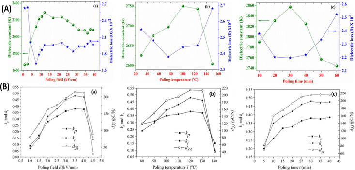 | ||
| Fig. 5 (A) Variation of the d33 value along with the electromechanical coupling factor (kp) with respect to the (a) poling field, (b) poling temperature, and (c) poling time at 25 °C, respectively; reprinted with permission from ref. 29. Copyright 2015, Springer. (B) Fluctuation of the d33 value along with the planar (kp) and thickness (kt) electromechanical coupling factor of KNLN6 ceramics with respect to the (a) poling field, (b) poling temperature, and (c) poling time; reproduced with permission from ref. 83. Copyright 2007 Elsevier. | ||
Recently a significant contribution was made by Tao et al. through comparing the poling conditions and d33 values of PVDF films fabricated via the fused filament fabrication (FFF) of commercial PVDF film. It was observed that the optimized poling conditions, stretching ratio (R), and d33 values of the FFF PVDF film were 30 V μm−1, 80 °C and 30 min, 4, and 7.29 pC N−1, respectively, which are lower compared with the commercial PVDF film d33 value of 28 pC N−1. The enhanced performance of the commercial PVDF film is due to its higher poling field (50 V μm−1) and stretching ratio (R > 4). However, the printed PVDF film has ∼10–100 times higher d33 and Fβ (65%) values, in contrast to previously specified PVDF reports.85–87 Different practical applications, such as pressure sensors, frequency detectors and wind energy harvesting, were also demonstrated using the printed PVDF film.88Fig. 6 illustrates the optimization of the poling conditions and stretching ratios through a comparison of the FFF-method-fabricated PVDF film and a commercial hot-pressed PVDF film.
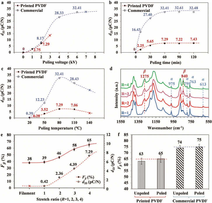 | ||
| Fig. 6 (a)–(c) Variation of d33 for printed PVDF and commercial PVDF with poling conditions (poling voltage, poling time, and poling temperature); (d) FTIR spectra of printed PVDF films with different stretching ratios (R = 1, 2, 3, and 4); (e) Fβ and d33 values of PVDF films before printing (filament) and after poling the printed PVDF films (R = 1, 2, 3, and 4) and; (f) stretch ratios and comparison of printed and commercial PVDF film Fβ values before and after poling; reproduced from ref. 88 with permission from the Royal Society of Chemistry. | ||
Tao et al. studied the strong dependency of the poling temperature on heavy-metal-doped KNNS-B(RE)NH ceramics and also reported better piezoelectric properties (d33 = 420–440 pC N−1) in a broad poling-temperature range of 35–120 °C. The fabricated device was poled using both DC and AC poling conditions of ∼30–120 °C, 3–4 kV cm−1 and 10 min, and the domain behaviour was also investigated by varying the poling temperature (Tp = 35–120 °C) and field (2–8 V) with an optimized heavy metal Dy content (x = 0–0.25). It was observed that with x = 0.25, Tp = 55–80 °C and a field of 4 V, complete domain orientation occurs.89Fig. 7 demonstrates the dependence of domain orientation and Tp, as well as the variation of the piezoelectric properties with the heavy metal content and poling conditions.
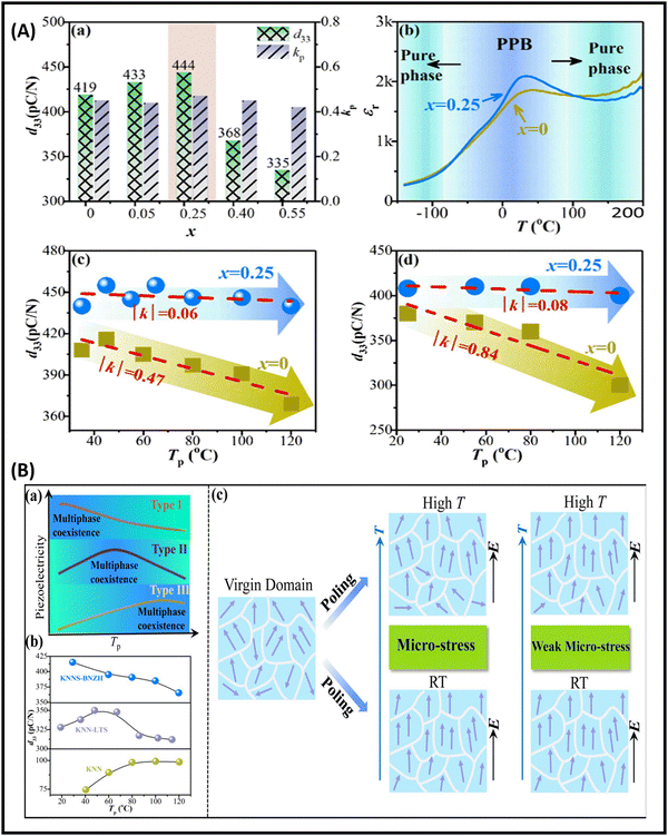 | ||
| Fig. 7 (A) Compositional and temperature difference of d33, kp, and εr: (a) fluctuation of d33 and kp values with heavy metal content (x = 0–0.55); (b) variation of εr with composition (x = 0–0.25) and Tp= −150 to 200 °C; and (c) and (d) variation of d33 with Tp with DC (c) and AC (d) poling with x (0–0.25). (B) (a) Dependence of d33 with Tp for KNN-based materials, (b) plots of d33 with respect to Tp for various KNN-based ceramics,90,91 and (c) schematic of domain behaviour with poling temperature and field; reproduced with the permission from ref. 89. Copyright Wiley publications. | ||
Although a variety of compounds, including lead-based and lead-free compounds,92–95 have been investigated, more research is still required, notably in terms of the poling effect, its circumstances, and property optimization, to contest lead-based materials.
7. Poling influence on lead-based ceramics, lead-free ceramics, polymers and composite materials
7.1. Lead-based piezoelectric materials
PZT is an inorganic material with the formula Pb[ZrxTi1−x]O3 (0 ≤ x ≤ 1). It belongs to the perovskite family (ABO3), which demonstrate strong piezoelectricity. PZT was first reported around 1952 by scientists of the Tokyo Institute of Technology. PZT materials outperform previously identified metal oxide-based piezo-materials such as BaTiO3 in terms of their operating temperature and sensitivity. In contrast to metal oxide-based barium titanate, PbZr0.52Ti0.48O3 has a higher operational temperature and sensitivity, making it one of the most commonly utilized piezoelectric materials in the world. PZT and lead titanate (PT) are ceramics that are used extensively in sensor and transducer applications because their characteristics can be modified through doping with various dopant.96–103,108 Most of the commercial products produced by PZT ceramics consist of a solid solution of PbTiO3/PbZrO3 compositions. In the doping process, a modest quantity of dopant is added to the piezoelectric ceramic to modify its characteristics. The substitution of dopants such as Ti4+/Zr4+ and La3+ or Bi3+ with Pb2+in PZT ceramics leads to a decrease in the ageing effect and coercive fields but an increase in the piezoelectric coupling factor, dielectric constant, and loss, respectively. These are also known as ‘soft ferroelectrics’ since they are generated by adding dopants with a higher valence. By contrast, dopants with a low valence are used in ‘hard’ ferroelectrics. Hard ferroelectric materials have a low dielectric loss and electrical resistivity, along with a greater coercive force, a reduced dielectric constant, and poling is often more challenging.99,104Fig. 8 illustrates the PZT-based piezoelectric nanogenerator (PENG) and its diverse applications.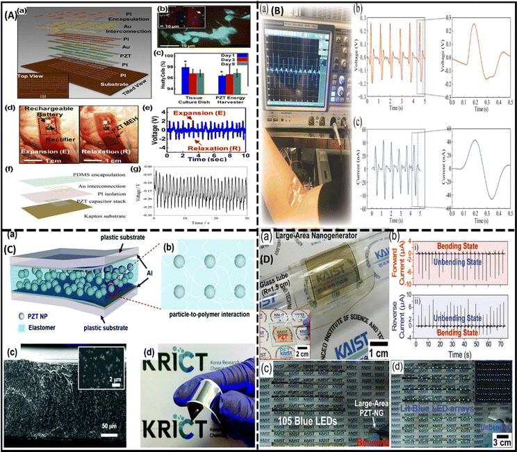 | ||
| Fig. 8 (A) Functioning of a PZT nanogenerator (NG): (a) schematic of a flexible PZT NG; (b) blue, green, and red fluorescent regions indicate the intact nucleus, live and dead smooth muscle cells, respectively, of rat cells placed on the surface of the NG; (c) comparative study of cell growth on culture plates and the device; and (d) and (e) incorporation of the NG into a bovine heart (d) and the respective output voltage (e); reproduced with permission from ref. 133. Copyright 2014, National Academy of Sciences. (f) Diagrammatic representation of the implantable thin-film based i-PENG PZT; and (g) measured voltage output of swine chest after anaesthesia; reprinted with permission from ref. 134. Copyright 2015 Springer Nature. (B) PZT-based PENG demonstration as a biosensor to detect the activity of a human arm: (a) verification of the PENG performance using an oscilloscope; and (b) and (c) generated voltage (b) and current (c) output developed by the bending and releasing movement; adapted with permission from ref. 135. Copyright 2020, American Chemical Society. (C) Self-powered system using PZT-NH2 NPs based flexible PENG: (a) device layers; (b) magnified scheme represents the particle to polymer interaction; (c) cross-sectional image of film and its particle to polymer interaction; (d) optical image of PZT-NH2 NPs based PENG device and its flexibility; reprinted with permission from ref. 136. Copyright 2018, Royal Society of Chemistry. (D) Working of a large-area PZT thin-film PENG prepared on a flexible substrate using a laser lift-off (LLO) method: (a) 3.5 × 3.5 cm PZT thin-film NG; (b) generated current signals via (i) forward and (ii) inverse finger-bending process; (c) array of 105 blue LEDs in series during finger bending; and (d) glowing of LEDs in a dark room when the thin film is released from the bending position; reproduced with permission from ref. 137. Copyright 2014, Wiley-VCH. | ||
Prewitt et al.105 poled commercial PZT ceramics with a poling field and temperature range of 0–20 kV cm−1 and 25–175 °C, respectively, for a constant poling period of 5 min using a silicone oil bath. The measured d33 value ranged from 0 to 413 pC N−1, indicating a powerful correlation between d33 and the poling parameters (temperature and E values). The effect of the poling time (15, 30, 45, 60 and 90 min) on the PZT ceramic was studied by Chaipanich et al. through poling the samples in an insulating medium at a 130 °C poling temperature and a field strength of 10 kV cm−1.106 The specimen that was poled for 45 min showed a higher d33 (28 pC N−1) compared with materials polarized for 15 or 90 min (16 pC N−1 and 22 pC N−1, respectively). Thus, 45 min was considered as the optimum poling time; also at this critical time (45 min), the electromechanical coupling coefficient (kp = 19.87%) was the highest.
Shifeng et al.107 poled a composite of PZT and sulphoaluminate cement with different PZT concentrations of 60, 70, 80 and 85 wt%. An increase in the d33 value occurred with an increase in the poling field strength (E) for poling time of 20 min at 120 °C, but above a 40 kV cm−1 electric field the d33 value decreased for the same poling parameters.
Marsilius et al. analysed two PZT samples (commercial grade), i.e., the soft-doped PZT 151 ceramic with a coercive field of 10 kV cm−1,119 and the hard-doped PZT 181 ceramic with a coercive field of 18 kV cm−1.119 Prepared samples were poled using nine different procedures in the temperature range of 150–45 °C with a poling field strength of 20–30 kV cm−1. The highest d33 value of ∼517 pC N−1 was shown by soft-doped PZT 151 compared with the hard-doped PZT 181 samples (270 pC N−1).
Guo et al. investigated the piezoelectric and dielectric behaviour of 〈001〉 and 〈011〉 oriented single-crystals of Pb(Mg1/3Nb2/3)O3–PbTiO3 near the metastable orthorhombic ferroelectric phase (FE0) region and demonstrated that, using a poling field of 10 kV cm−1, extraordinarily high d33 values of up to 2500 pC N−1 can be reached, due to the irreversible polarization from the monoclinic phase space group Cm (MA) to space group Pm (MC).109 Bian et al. fabricated the BT-based 0.55Pb(Ni1/3Nb2/3)O3–0.15PbZrO3–0.3PbTiO3 (PNN–PZT–xBT) highly orientated[001]C textured ceramic using a templet grain growth method and achieved higher piezoelectric properties (d33 = 1210 pC N−1,  at 5 kV cm−1) and a figure of merit (g33 × d33 = 21.92 × 10⁻¹² m2 N−1) that are greater (13%, 54%, and 68%, respectively) than for the PNN–PZT composite without BT.110
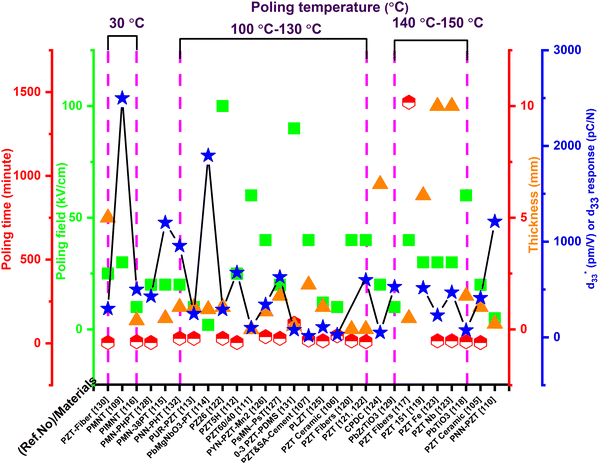
Guo et al.109 investigated two piezoelectric materials PMNT and PZNT. Three compositions were examined as per the phase transition behaviour and properties of the crystal, and the samples (containing distinct PT contents) were poled at different field strengths of 20–30 kV cm−1 using a silicone oil insulating medium, and the d33 values investigated. It was observed that d33 increased to 1550 pC N−1 with a poling field of 10 kV cm−1, and a sharp increment of d33 2500 pC N−1 occurred with a field of 30 kV cm−1. Table 1 summarizes the poling conditions (field strength, temperature, time, and thickness) as well as the d33 or  values of the poled lead-based materials. On the basis of the Table 1 data, we have prepared a schematic graph (Fig. 9).
| Lead-based materials | Poling conditions | d 33 (pC N−1) or (pm V−1) | Ref. | |||
|---|---|---|---|---|---|---|
| Field strength (kV cm−1) | Temperature (°C) | Time (min) | Thickness (mm) | |||
a RT = Room temperature.
b Represents the  value. value.
|
||||||
| PZT60/40 films (100) | 60 | — | — | 0.0009 | 100 | 111 |
| PZT-5H | 25 | 100 | — | 5 | 677 | 112 |
| PUR-PZT | 10 | 100 | 30 | 1 | 246 | 113 |
| PMNT and PZNT | 30 | RTa | — | — | 2500 | 109 |
| 0.67Pb(Mg1/3Nb2/3)O3–0.33PbTiO3 (PbMgNbO3–PbTiO3) | 2 | 100 | — | 0.9 | >1900 | 114 |
| PZT and sulphoaluminate cement | 40 | 120 | 20 | 2 | 16 | 107 |
| PMN–38PT <110> | 20 | — | — | 0.5 | 1200 | 115 |
| PIMNT | 10 | RTa | 10 | 0.4 | >500 | 116 |
| PZT ceramic | 10 | 130 | 45 | — | 28 | 106 |
| PZT nanofibers | >40 | 140 | 1440 | 0.5 | — | 117 |
| PbTiO3 | 60 | 170 | 10 | 1.5 | 75b | 118 |
| PZT ceramic | 20 | 25–175 | 5 | 1 | 413 | 105 |
| PZT 151 | 20–30 | 150 | — | 6 | 517 | 119 |
| PZT nanofibers | 40 | 130 | 15 | 0.005 | — | 120 |
| PZT nanowires | 40 | 130 | 10 | 0.005 | 600 | 121, 122 |
| PZ26 | 100 | ∼100 | 30 | 1 | 290 | 122 |
| PZT Fe | 30 | 160 | 15 | 10 | 230 | 123 |
| PZT Nb | 30 | 160 | 15 | 10 | 470 | 123 |
| Cellulose paper derived ceramics (CPDC) | 20 | 130 | — | 6.5 | 50 | 124 |
| PLZT | — | — | — | — | 108 | 125 |
| PYN–PZT–Mn2 | 40 | 120 | 40 | 0.8 | 343 | 126 |
| (1−x)[(Pb1−ySry)(Mg1/3Nb2/3)O3]–x(Pb1−ySryTiO3) (PsMN–PsT) | 20 | 120 | 30 | ∼1.5 | 630 | 127 |
| 0.15Pb(Mg1/3Nb2/3)O3–0.38PbHfO3–0.47PbTiO3 (PMN–PHPT) | 20 | RTa | 5 | — | 428.3 | 128 |
| PbZr0.4Ti0.6O3 | 10 | — | — | — | 528 | 129 |
| PZT fiber | 25 | RTa | 5 | 5 | 300b | 130 |
| 0–3 PZT–PDMS | Corona poling (90) | 120 | 120 | 0.130–0.165 | 78.33 | 131 |
| 0.49Pb(Ni1/3Nb2/3)O3–0.51Pb(Hf0.3Ti0.7)O3 (PNN–PHT) | 20 | — | 30 | 1 | 957 | 132 |
| PNN–PZT | 5 | — | — | 0.25 | 1210 (1773b) | 110 |
7.2. Lead-free piezoelectric materials
In the early 2000s, the main challenge with piezoceramics was the use of lead-based compounds, which needed to be replaced with lead-free compounds. Environmental rules, such as the Waste Electrical and Electronic Equipment (WEEE) regulations and restrictions on some harmful toxins via the Restriction of Hazardous Substances (RoHS) directive, prohibited the use of lead-based materials. However, due to their strong piezoelectric capabilities, lead-based materials have a large commercial share in piezoelectric-related applications. Several research organizations have attempted to create lead-free piezoelectric materials as a substitute for lead-based ceramics. Numerous lead-free ceramics have already been discovered that have improved electromechanical characteristics. These materials, however, have the disadvantage of a weak depolarizing temperature, during which their piezoelectricity begins to deteriorate. The most efficient method for producing controlled-textured-based lead-based piezoelectric ceramics are the templated grain growth (TGG) method. TGG was used to boost the piezoelectricity of textured lead-free ceramics. As demonstrated by Saito et al.,187,198,199 their non-toxic textured ceramic excellent strain compared with marketable lead-based materials, and it also showed high reliability at an optimized temperature range. Many textured lead-free materials, such as (Bi,Na)TiO3 (BNT)187,198 and (K,Na)NbO3 (KNN),199 have been produced that show enhanced d33 values along with a good output performance. Recently Panda et al. reviewed an article based on the higher d33 values of lead-free piezoceramic and composite materials (BCTZ, BCSnT, BCHfT, and KNN), and explained the mechanism for obtaining their higher piezoelectric properties as well as the probable future aspects for their further enhancement.138Fig. 10 shows some examples of the three main groups of lead-free piezoelectric perovskite materials (BT, KNN, and NBT) that are used due to health and environmental concerns.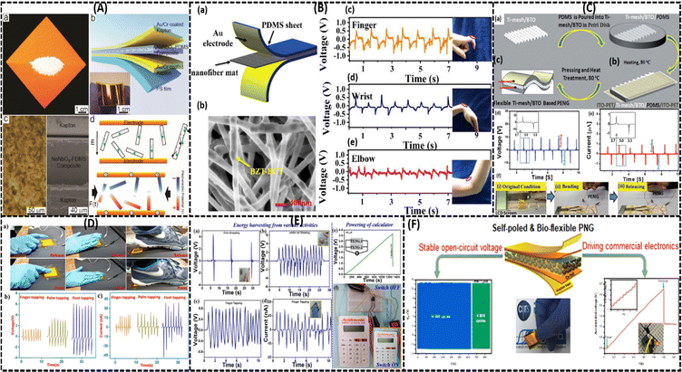 | ||
| Fig. 10 Application of lead-free NaNbO3, BCT–BZT, BaTiO3–TiO2, Bi4Ti3O12–PDMS, BTO–PVDF and BCZTO piezoelectric nanogenerators (PENGs) in various areas. (A) schematic of NaNbO3-based PENG: (a) image of NaNbO3 nanowires; (b) schematic of a NaNbO3–PDMS fabricated PENG; (c) optical microscope and SEM images; and (d) dipole alignments of the ferroelectric nanowires via the poling process; reproduced with permission from ref. 139. Copyright 2011, ACS Publications. (B) Lead-free flexible BCT-BZT fabrication and its real-time applications: (a) schematic of fabricated BCT–BZT PENG; (b) SEM image of the composite nanofiber mat; and (c)–(e) demonstration of the output voltage using finger (c), wrist (d) and elbow (e) movements; reproduced with permission from ref. 140. Copyright 2020, Elsevier. (C) Lead-free flexible and transparent BaTiO3–Ti-mesh PENG as an energy harvester: (a)–(c) device-fabrication process of BTO on a Ti substrate; (d) and (e) device output voltage (d) and current (e) during bending and relaxing conditions; and (f) optical images of the LCD in connection with the PENG, which is turned on and off with the bending and releasing mode, respectively; adapted with permission from ref. 141. Copyright 2016, Royal Society of Chemistry. (D) (a) Optical images of the Bi4Ti3O12–PDMS composite PENG sensing application tested using finger (left), palm (middle), and foot (right) movements; and (b) and (c) output voltage (b) and current (c) measurements with respect to these motions; reproduced with permission from ref. 142. Copyright 2019, Elsevier. (E) Testing of the BTO-PVDF PENG using (a) a coin-dropping method, (b) attached to a fan, and (c) and (d) the obtained output voltage (c) and current (d) generated via a finger-tapping method; (e) connection of two PENG10 devices with a capacitor (10 μF), and (f) functioning of a calculator powered by the PENG; reproduced with permission from ref. 143. Copyright 2021, MDPI. (F) Self-poled and bio-sustainable (BCZT-based polydopamine-embedded) BF-PNG showing an open-circuit voltage of 14.4 V and a short-circuit current of 0.55 μA under general finger tapping; reproduced with permission from ref. 144. Copyright 2021, Elsevier. | ||
An increment in the density of the 90° domain wall areal dimension was observed in the BaTiO3 ceramic when the applied poling conditions were 5 kV cm−1, 105 °C and 30 min, which helped to enhance the d33 value and relative dielectric constant (εr) at room temperature.167 The BZT-BCT solid solution shows higher d33 coefficient values (630 pC N−1) and kp values under the ideal poling conditions of 2.5 kV cm−1 at 40 °C for 20 min.168
Previously Liu et al. achieved higher d33 values of 620 pC N−1 in the lead-free system BZT-xBCT system near the morphological phase boundary (MPB) region.152 Later Mayamae et al. investigated the lead-free 0.9BaTiO3–(0.1 − x)CaTiO3–xBaSnO3 (BCT–xBS) system for actuator applications. With poling conditions of 40 kV cm−1, room temperature, and 30 min, enhanced piezoelectric properties of kp = 41.7%, d33 = 469 pC N−1 and  were achieved for the x = 0.05 BS content and an electric field of 10 kV cm−1 under ambient conditions near the orthorhombic–tetragonal (T–O) phase transition.169 Similarly, Chen et al. proposed higher d33 = 650 pC N−1, kP = 59.6%, and Pr = 10.2 μC cm−2, which were attained by doping Y3+ (x = 0.03) in the BCTS ceramic near the morphological phase boundary with poling conditions of 35 kV cm−1 at room temperature for 15 min.170 Recently, d’Ambrogio et al. fabricated a BaTiO3–PDMS based piezoelectric sensor for the diagnosis of coronary stenosis by adopting the novel technique dielectrophoresis, and showed that the BaTiO3–PDMS bio-sensor exhibited higher piezoelectric properties for a high-temperature range and with a lower poling field of 25 V μm−1 compared with PVDF-based polymers (60 V μm−1) at 80 °C for 30 min.171
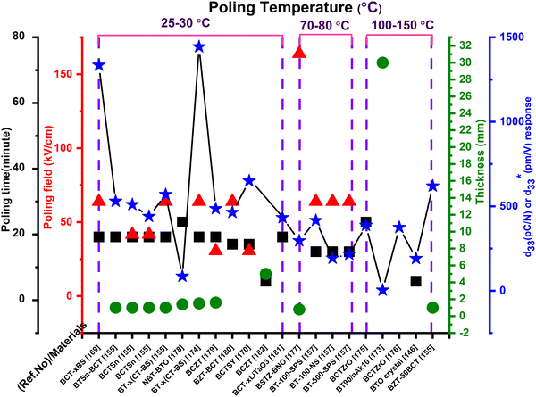
Highly advanced instruments such as scanning tunnelling microscopy (STM) and atomic force microscopy (AFM) employ piezoelectric devices because of their good electro-mechanical performance. A piezoelectric device that has a higher transduction mechanism will show a maximum output response. This type of activity contributes to higher values of the longitudinal d33.146,172 In addition to d33, other parameters, such as the dielectric constant, electromechanical coupling factor, leakage current, dielectric loss, and quality factor, are necessary and determine whether or not the device will be suitable for a particular application.147 As discussed before, piezoelectric coefficient values are highly influenced by the poling conditions, and Table 2 shows the reported d33 or  values that are dependent on the poling effect. Based on data in Table 2 a graph was plotted (Fig. 11), which illustrates the impact of the poling conditions on the piezoelectric coefficient of BT-based piezoelectric materials.
| BT-based materials | Poling conditions | d 33 (pC N−1) or (pm V−1) | Ref. | |||
|---|---|---|---|---|---|---|
| Field (kV cm−1) | Temperature (°C) | Time (min) | Thickness (mm) | |||
a RT = Room temperature.
b Represents the  value. value.
|
||||||
| BaTiO3 (BT-100-SPS) | 30 | 80 | 30 | — | 416 | 157 |
| BaTiO3 (BT-100-NS) | 30 | 80 | 30 | — | 193 | 157 |
| BaTiO3 (BT-500-SPS) | 30 | 80 | 30 | — | 216 | 157 |
| BaTiO3 ceramic | 10 | 120 | — | 191 | 146 | |
| BaTiO3 and nano-akermanite, (BT/nAK) BT90 | Corona poling | 110 | — | 30 | 4 | 173 |
| BT–x(CT-BS) | 40 | RTa | 30 | 1.5 | 1444b and 570 | 174 |
| 0.9BaTiO3–(0.1 − x)CaTiO3–xBaSnO3 [BCT–xBS] | 40 | RTa | 30 | — | 1335b and 469 | 169 |
| Ba(Ti0.88Sn0.12)O3–30(Ba0.7Ca0.3)TiO3 | 40 | RTa | 30 | ∼1 | 530 | 155 |
| Ba(Zr0.2Ti0.8)TO3–50(Ba0.7Ca0.3)TiO3 | — | — | — | ∼1 | 620 | |
| (Ba0.98Ca0.02)(Ti0.96Sn0.04)O3 | 40 | 28 | 20 | ∼1 | 510 | |
| (Ba0.97Ca0.03)(Ti0.94Sn0.06)O3 | 40 | RTa | 20 | ∼1 | 440 | |
| BT–x(CT-BS) | 40 | RTa | 30 | ∼1 | 570 | |
| (Ba0.93Ca0.07)(Ti0.95Zr0.05)O3 | 50 | — | 387 | 175 | ||
| (Ba1−xCax)(Ti0.98Zr0.02)O3 | — | — | — | — | 375 | 176 |
| BSTZ-BNO | 180 | 65 | 75 | 0.8 | 296 | 177 |
| 0.94Na0.5Bi0.5TiO3–0.06BaTiO3 | 50 | RTa | 1.4 | ∼86 | 178 | |
| (Ba0.85Ca0.15)(Zr0.1Ti0.9)O3 (BCZT) | 40 | RTa | 15 | — | ∼486 | 179 |
| Ba0.90Ca0.10Ti0.90Sn0.10O3–xY2O3 (BCTSY) | 35 | RTa | 15 | — | 650 | 170 |
| (1 − x)Ba(Zr0.2Ti0.8)O3–x(Ba0.7Ca0.3)TiO3 | 35 | 30 | 30 | 1.6 | 464 | 180 |
| (Ba0.85Ca0.15)(Zr0.10Ti0.90)O3–xLiTaO3 | 40 | RTa | — | — | 433 | 181 |
| (Ba0.85Ca0.15)(Zr0.1Ti0.9)O3 | 10 | RTa | — | 5 | — | 182 |
Recently Camargo et al. investigated the lead-free BNKT piezoceramic, and showed that higher piezoelectric properties (d33 = 129 pC N−1 and d31 = 12.8 pC N−1) and an output voltage of 19.9 V g−1 were achieved, and that these materials can be successfully applied as energy harvesters instead of lead-based toxic materials.186
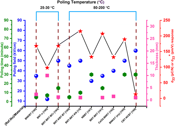
In BNT materials, texturing is achieved via the reactive-templated grain increment process, using particles such as Na0.5Bi4.5Ti4O15 (NBiT) or Bi4Ti3O12 (BiT). Current research has established ways for converting plate materials such as NBiT or BiT particles into templates of pure-phase BNT.187,188 Some of the accumulated poling parameters with d33 values are listed in Table 3. Based on the data in Table 3 a plot (Fig. 12) has been prepared.
 values with respect to their optimized poling conditions
| BNT based materials | Poling conditions | d 33 (pC N−1) (or) (pm V−1) | Ref. | |||
|---|---|---|---|---|---|---|
| Field (kV cm−1) | Temperature (°C) | Time (min) | Thickness (mm) | |||
a RT = Room temperature.
b Represents the  value. value.
|
||||||
| BNT–KBT–BT100x | 45 | 80 | 5 | — | — | 189 |
| BNKBT–5 | 35 | RTa | 5 | 2.3 | 168 | 190 |
| BNT–BKT | 35 | 90 | 15 | 1 | 207 | 191 |
| CeO2 doped BNaKT | 40 | 1.5 | 132 | 192 | ||
| BNT (BNT–BKT–KN100x/100y/100z) | 50 | 80 | 10 | 1 | 215 | 15 |
| (1 − x − y) BiNaTiO3–BiKT–yBiCrO3 | 50 | 40 | 15 | 1.2 | 168 | 194 |
| BNKAT (x/y) | 50 | 80 | 30 | — | 189 | 195 |
| BNT + BiO2O3x [BNT-x] | 12 | RTa | 7 | 10 | 98 | 196 |
| NBBT | 30 | 80 | 30 | — | 133 | 197 |
| NCBT conventional | 60 | 200 | 30 | 1 | 13b | 198 |
A surprisingly high d33 value of ∼570 ± 10 pC N−1 was achieved by Xu et al. in the KNNS-BZ-BKH system with poling conditions of 20–40 kV cm−1 at room temperature for 20 min, due to the combination of nanoscale strain domains with the higher density ferroelectric domain wall.206 Similarly, Li et al. investigated the electrical and piezoelectric properties of the KNN–ZN, KNN–BF, and KNN–AL composites prepared via a femtosecond laser (FL) microprocessing spin-coating method with poling conditions of 35 kV cm−1 at room temperature and 20 min. A higher d33 value of 128 pC N−1 along with a kp of 0.41 were achieved in the KNN-ZN system; moreover, better knowledge the energy-band structure of the system was studied using a density functional theory (DFT) approach.207 Recently, Song et al. reached temperature stability in the range of 25–150 °C along with a higher piezoelectricity d33 = 508 pC N−1 and a piezoelectric strain of 0.18% by adopting a facile approach with doping by Li and Sb in the monoclinic KNN ceramic, which is greater compared with other KNN composites.208
The parallelism between electrical poling (DC loaded) and unipolar cycling together in lead-free and lead-based piezoelectric materials has already been demonstrated in the literature.209,210 The notion of space charge concentration around the grain boundaries210–212 can explain the unipolar cycling behaviour, which is responsible for the appearance of an intrinsic biased field (Eint) and gradual reduction of the piezoelectric characteristics. High-temperature poling may also cause the formation of a significant Eint, which reduces the performance of piezoelectric elements. As a result, it is logical to anticipate that the space charge concentration may possibly induce the degradation of piezoelectricity at higher poling temperatures. As the poling process of KNN-based piezo materials is still controversial, and the significance of the space charge density in the poling method has received less consideration, it is vital to investigate the temperature dependence of poling characteristics.
The d33 or  values and poling conditions of KNN-based materials are listed in Table 4, from which we can conclude that poling greatly affects the d33 value, although this is still small compared with the values of PZT-, BT- and BNT-based materials. These materials (KNN based) are used frequently in storage devices (in memory devices, and energy-storage devices), and in solar-energy-conversion applications.213 A schematic (Fig. 13) has been prepared using the poling conditions of KNN-based materials that are collected in Table 4.
| KNN based materials | Poling conditions | d 33 (pC N−1) | Ref. | |||
|---|---|---|---|---|---|---|
| Field (kV cm−1) | Temperature (°C) | Time (min) | Thickness (mm) | |||
| (K0.50Na0.50)NbO3 | 35 | 120 | 30 | 1.5 | 125 | 214 |
| KNN–xBA–BNZ | 11.56 | 27 | — | 5 | 306 | 215 |
| KNN-CT-1: 0.96(K0.5Na0.5)NbO3–0.04CaTiO3 | 30 | 80 | 30 | 1 | — | 216 |
| KLN-CZ-1: 0.96(K0.5Na0.5)NbO3–0.04CaZrO3 | 30 | 80 | 30 | 1 | — | 216 |
| KNN-CZ-2: 0.96(K0.5Na0.5)NbO3–0.04CaZrO3 + 0.03Zr | 30 | 80 | 30 | 1 | 160 | 216 |
| KNN-CZ-3: 0.98(K0.5Na0.5)NbO3–0.02CaZrO3 + 0.03ZrO2 | 30 | 80 | 30 | 1 | 130 | 216 |
| (K0.5Na0.5)NbO3(CuO doped) | 50 | 100 | 10 | 0.7 | 86 | 217 |
| (K0.476Na0.524)NbO3 (Cuo doped) | 30 | 120 | 10 | 5 | 146 | 218 |
| K0.5Na0.5Nb0.97Sb0.03O3 (KNNS1) | 30 | 120 | 10 | 1 | 218 | 219 |
| (Ag0.75Li0.1Na0.1K0.05)NbO3(ALNKN–xCuO, x = 1 mol%) | 50 | 100 | 20 | 1 | 47 | 220 |
| (KNL–NTS) | 40 | — | 30 | 0.7 | 270 | 221 |
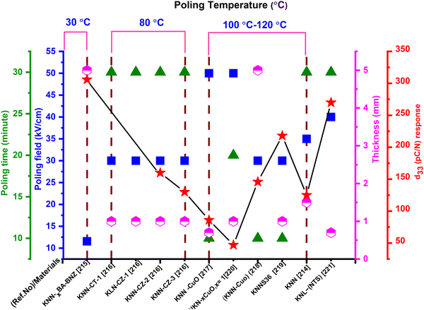 | ||
| Fig. 13 Poling behaviour of KNN-based piezoelectric materials based on the data in Table 4. | ||
| PVDF nanoparticles with filler | Poling conditions | d 33 (pC N−1) (or) (pm V−1) | Ref. | |||
|---|---|---|---|---|---|---|
| Field strength (kV cm−1) | Temperature (°C) | Time (min) | Thickness/needle distance (mm) | |||
a RT = Room temperature.
b Represents the  value. value.
|
||||||
| P(VDF-HFP) | 100 | 100 | 1200 | — | 180 | 267 |
| PVDF–BaTiO3 nanoparticles | 1000 | 120 | 30 | 13 | 25 | 268 |
| PVDF–BaTiO3 fibers | 350 | 100 | 120 | 0.33 | 11.4b | 147 |
| P(VDF-TrFE) | 500 | — | — | 0.060 | 35.3 | 269 |
| PVDF–ZnO nanoparticles | 50 | 120 | 0.010 | 900 | 270 | |
| P(VDF-TrFE)/ZnO | Corona poling | 5 | 0.35, grid to sample 5 | −22 | 271 | |
| PVDF–ZnO nanowires | 1200 | — | — | ∼0.004 | — | 272 |
| PVDF–PZT powders | 100 | 80 | — | 0.030 | 84 | 274 |
| PVDF–CoFe2O4 nanoparticles | Corona poling | 80 | 30 | — | 33 | 275 |
| PVDF–Fe3O4 nanoparticles | 350 | 60 | 60 | 0.035 | 37 | 276 |
| PVDF-micro-CaCO3 and Mt particles | Corona poling at 900 | — | 10 | 0.100 | 30.6 | 298 |
| PVDF-MWCNTs | 1500 | 100 | 30 | — | 23 | 277 |
| PVDF-MWCNTs | Electrospinning 120 | — | — | Needle distance 0.5–1 mm | −57.6 | 278,279 |
| MWCNTs coated with TiO2 | 1200 | 70 | 80 | 0.02 | 41 | 280 |
| PVDF-C60 and SWCNTs | 4000 | 80 | 20 | 0.05 | 65 | 281 |
| PVDF-graphite nanosheets | 500 | 130 | 30 | — | 6.7 | 283 |
| PVDF-reduced graphene oxide (PVDF-rGO) | Corona poling at <50 | 60 | 30 | 0.050 | 16.66b | 284 |
| PVDF-MnO2/graphene/MWCNT hybrid | 800 | — | — | 0.012 | 17–33 | 286 |
| PVDF 6010 | Corona poling of <30 | RTa | 30 | ∼1.5 | ∼264 | 287 |
| PVDF composite | 700 | — | — | 0.035 | 140 | 288 |
| PVDF composite | 20 | — | 120 | — | −5 | 285 |
The molecular alignment and arrangement of the polymer matrix in the composition are responsible for the piezoelectricity in the PVDF polymer and its co-polymers. In order to achieve piezoelectric properties, a bulk polymer configuration must have molecular dipoles. Furthermore, the molecular dipoles should be able to reorient inside the matrix of the bulk material while maintaining their desired alignment site. Adjustment of the dipoles in the matrix is accomplished using the poling technique. PVDF has four phases, which are α, β, γ, and δ, among which the β phase shows the highest piezoelectricity behaviour. β-PVDF films are generally attained via elongating α-phase films.230,231 The temperature and stretching proportion will decide the β-phase percentage and crystallinity, which influences the electroactive characteristics of the polymer. After obtaining the β phase, poling is carried out and the dipoles are aligned in the presence of a high E, boosting the material's piezoelectric response.232,233 The stretching proportion and the temperature at which the phase transition occurs from the α to the β phase also affect the switching mechanism.234,235
An wide-ranging study has been conducted to enhance the β-phase percentage in PVDF through solvent casting, phase transition, or the synthesis of PVDF-copolymers. Mechanical drafting/annealing in the presence of a high temperature and pressure is required to obtain the necessary ferroelectric β-PVDF phase. A detailed study236,237 has been carried out on the high-pressure crystallization of PVDF in both low and high melting phases. In their preliminary studies, Yang et al.236 discovered that by quenching and subsequently annealing the PVDF sheets, β-phase crystallisation is induced instantly from the melt. The α-PVDF phase was extracted straight from the melt.238–240 Then the stretching, annealing or poling procedure241 was executed for β-phase induction.
In 1969, Kawai was the first to reveal piezoelectricity in PVDF through the application of a strong field and mechanical stretching.242,243 For significant piezoelectric characteristics, PVDF must have a high percentage of the electroactive β-phase. Mechanical stretching and traditional poling techniques such as electro-poling or corona discharge can be used to achieve the polar β-phase in the initial stage. Conventionally, the polarity of PVDF was achieved using mechanical stretching and the electro-poling or corona discharge technique. Although β-phase PVDF is appealing for generating an adequate electrical performance, monomer alignment is a tedious process and requires costly equipment with the application of high electrical fields. The challenge with the traditional poling method is that E can only be supplied at the surface of the sample, which gives rise to various kinds of stress and strain.244 Kawai adapted the uniaxial drawing process for development of PVDF film, but the film contains higher nonpolar α-phases due to the weak crystallization.242,245 Moreover, the phase transformation from α-phase to β-phase is rarely successful, i.e., about 20% of the α phase still retained in the PVDF material. The above-described conventional process can only be used to make films with a depth of a few millimetres. The disadvantages of these old methodologies are solved by the electrospinning process, the solvent-evaporation method, and the spin-coating technique,246–248 and they have gained increasing interest since films of nanoscale thickness are required in numerous applications.
To produce greater piezoelectricity, all of the approaches listed above involve extra poling or mechanical elongation of the PVDF film. Electrospinning, by contrast, is a compressive and reliable process that utilizes electrostatic forces for the production of nanofibers from a liquid polymer melt or solution.249,250 The electrospinning setup comprises a higher-power supply unit, a spinneret, a syringe pump, and a grounding collector.251 Once the power is switched on, the applied E overwhelms from the surface tension of the droplets and a conical-shaped polymer jet solution known as a Taylor cone is ejected. The mixture evaporates after reaching the earthed collector, generating randomly distributed thin polymer fibres, where the size, and microstructure can be adjusted through modifying numerous parameters.252,253 So, the production of PVDF nanofiber films through electrospinning is regarded to be the most efficient method because it is easy to perform, cost-effective, and the voltage supplied throughout the synthesis enables the preferred β-phase PVDF to be acquired. A suitable perpendicular mechanical loading or bending or twisting or stress/strain need to be applied on the polarized β-PVDF film, which results in the generation of desirable quantity of voltage.254 The method has the benefit of enhancing the piezoelectricity in situ during the production of nanofibers.245 As a result, because the poling method includes characteristically exposing PVDF to a high E, electrospinning is a beneficial approach for fabricating sophisticated polymer films.
In addition to the popularly used electrospinning method, the newly introduced additive manufacturing (AM) process is used for the production of continuous printable piezoelectric samples from polymeric PVDF filament rods in the presence of a strong E. This procedure is popularly known as the electric poling-assisted additive manufacturing (EPAM) process of β-phase PVDF, which includes AM as well as the electric poling technique and can consistently produce free-form shape piezoelectric equipment.255 This technique enables the homogenous alignment of electric dipoles in preferred orientation, which helps to manufacture large area films with the user required designs. During the EPAM method, melted PVDF polymer is mechanically stressed by the leading nozzle tip as well as being poled by a strong E in a higher poling temperature bed. The EPAM technique is used efficiently for the production of piezoelectric devices. This procedure does not lead to dipole alignment of the PVDF polymer in the absence of an electric field. The EPAM technique is assumed to apply hugely in AM for making a wide range of piezoelectric PVDF polymer-composite devices for energy harvesting, sensing and actuator purposes using easy, single and cost-effective processing and fabrication steps.256,257 Furthermore, the newly used self-poling method is also an advantageous process for improving β-PVDF and its composites.258
Because of the diverse applications of PVDF, there are numerous studies related to PVDF and composite-based polymers.232,233,259 PVDF and its copolymers have d33 values that vary from 12 to 33 pC N−1, which is extremely small in comparison with the d33 values of other bulk polymers.57,260–266 Despite this limitation, PVDF and its co-polymers have received huge appreciation due to their inherent characteristics, such as larger piezoelectric strain coefficient values, high flexibility, high elastic compliance, excellent chemical resistance to solvents, bases and acids, greater electro-mechanical coupling capability, required mechanical strength, and biocompatibility.273,282Fig. 14 is plotted based on the different poling parameters presented in Table 5.
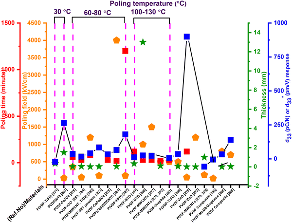 | ||
| Fig. 14 PVDF and PVDF-based composites’ d33 or d33 response in accordance with the poling parameters shown in Table 5. | ||
8. Applications
In congruence with the evolution of microelectronics industries, it has become necessary for the invention of flexible, wearable and self-powered PENGs by employing the piezoelectric phenomena. The benchmark for fabricating a sophisticated PENG are (i) it needs to be firmly attached to the operator, (ii) it is lightweight, (iii) it has a long life span with high stability, (iv) it is self-executable, and (v) it is commercially viable and inexpensive. In addition to these requirements, from a practical implementation point of view, it should be suitable and comfortable for the user. In particular, for achieving exceptional futuristic and realistic PENGs, the poling techniques and conditions are necessarily tailored.28,289–291 In the literature, numerous PENGs have been framed by proper parameters resulting in an enhanced performance. This section outlines some of the flourishing applications of optimized poled devices for commercial and biomedical purposes.Nilsson et al. demonstrated the effect of the PVDF-bio-fibre composite with polyethylene or carbon black as a core portion under optimized poling conditions of 60–120 °C, E = 1000 kV cm−1, and 2 min.292 The textile PENG with a polyamide yarn configuration was successfully implemented as a textile sensor for heartbeat monitoring, and reported a maximum output voltage and power of ∼4 V and 15 nW, respectively. Later Soin et al.222 constructed an energy harvester ‘3D spacer’ PENG through the weft knitting of a PVDF monomer filament with a yarn of polyester, and Polyamide 66 coated with Ag metal to compensate for the 2D configuration disadvantages.222,293,294 In the 3D textile PVDF monofilament, the beta-phase concentration was increased up to 85% via the application of an electric field of 6 kV cm−1 at the temperature range of ∼80–90 °C, and the device produced a power of ∼5.07 μW cm−2, which is five times higher compared with a 2D textile PENG (1.18 μW cm−2). Fig. 15 gives the configurations and output results of 2D and 3D structured textile devices.
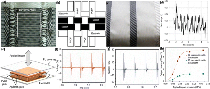 | ||
| Fig. 15 Relative study of the structural, morphological and electronic characteristics of flexible fluoropolymer textile PENGs. (a) Structure of a flexible PVDF-based 2D woven PENG; and (b) the highlighted sensing area; reproduced from ref. 295. Copyright 2013, Wiley publication. (c) Textile pattern formed by the woven fibres and (d) signal produced from the heartbeat via the respiration process; reprinted from ref. 292. Copyright 2013, Elsevier publication. (e)–(g) 3D configuration of a piezo-fabric energy harvester (e), with its temporal voltage (f) and current (g) outputs (obtained by applying a pressure of 0.034 MPa with a load of 470 kΩ); and (h) correlating the output power of 2D and 3D woven PENGs with applied pressure; adapted with permission from ref. 222. Copyright 2014, Royal Society of Chemistry. | ||
Aliane et al.296 studied the dielectric, piezoelectric, ferroelectric, and pyroelectric behaviour of the P(VDF-TrFe) copolymer on the basis of its crystallinity and polymer chain dimensions. For the piezo-activation purpose, the fabricated P(VDF-TrFe) device (2 μm thickness) was poled with voltage of 80 V for 5 min at 85 °C. The fabricated sensor maximum output voltage was analysed by varying the time and pressure with the degree of dislocation (δZ) and the d33 value on the basis of the AC frequency. In 2017, Yaqoob et al.297 fabricated a tri-layer flexible PENG where the polyvinylidene fluoride–barium titanate (PVDF–BTO) nanocomposite stacks act as the top and bottom layer and an n-type graphene film was inserted in between these two layers. For an enhanced output, the PENG was poled with a field strength of 150 kV cm−1 at 100 °C for 1 h. The tri-layer configuration can generate maximal peak-to-peak voltage, current, and power values of up to 10 V, 2.5 μA, and 5.8 μW, respectively, in the presence of a 2 N force at 1 MΩ load resistance. Moreover, the structure demonstrates excellent stability for 1000 press-and-release periods (Fig. 16). Subsequently, Jahan et al.298 studied the stretching behaviour of a hybrid PVDF-based composite (micro-CaCO3 + montmorillonite (Mt)) prepared using a co-rotating twin-screw extrusion technique with various contents of CaCO3 (30–40 wt%). The poling conditions were adjusted to a 900 kV cm−1 field strength at ambient temperature for 10 min and stretching percentage to obtain a maximum d33 value of 30.6 pC N−1 and the highest beta-phase in the PVDF matrix.
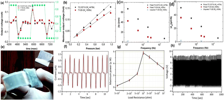 | ||
| Fig. 16 Electrical and mechanical characterisation of P(VDF-TrFe)- and PVDF–BTO-based PENGs. (a) and (b) voltage variation with time (a) and pressure (b) for the piezoelectric sensors (direct method); (c) and (d) displacement and d33 fluctuation, respectively, over the AC field; reprinted with permission from ref. 296. Copyright 2015, Elsevier. (e) Flexibility testing of the tri-layer structure by bending; (f) and (g) PVDF-BTO PENG maximum current (f) and power (g) output result, and (h) tri-layer device stability testing over 1000 stress-and-release cycles; reproduced with permission from ref. 297. Copyright 2017, Elsevier. | ||
Recently Liu et al. prepared the poly(vinylidene-trifluoroethylene)–polyhedral oligomeric silsesquioxane (P(VDF-TrFE)–POSS) composite-based piezoelectric nanogenerator via the minimum-temperature solvent-evaporation procedure, and confirmed the mean output current density (0.5 μA cm−2) and voltage (3 V) using the optimum poling parameters of 100 °C, 800 kV cm−1 for 2 h at 5 Hz frequency.299 In the same year, Yang et al.300 developed a BTO–PVDF composite with a polydiacetylene (PDA) surface modifier-based wearable-flexible pressure sensor via a facial solution-casting procedure and poled the PENG with an E of 50 mV m−1 at the poling temperature of 90 °C for 4 h. With 17% PDA, the doped BTO–PVDF composite displaced a quick action of 61 ms and showed excellent voltage and power output values of 9.3 V and 0.122 μW cm−2, respectively, with a load of 70 MΩ. The output characteristics of the P(VDF-TrFE)–POSS PENG and the fruitful implementation of the BTO–PVDF composite sensor as a wearable device for the detection of human movement are shown in Fig. 17(A and B).
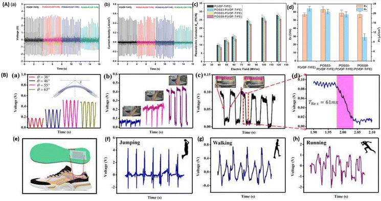 | ||
| Fig. 17 (A) Comparative study of the voltage, current, d33 and ferroelectric properties of pure P(VDF-TrFE) and doped P(VDF-TrFE)–POSS PENGs; reprinted with permission from ref. 299. Copyright 2020, Royal Society of Chemistry. (B) Demonstration of the bending and twisting activity of the flexible BTO–PVDF constructed PENG and the output performance of the piezoelectric sensor, fixed to a shoe, with different movement activities; reproduced with permission from ref. 300, Copyright 2020, Elsevier. | ||
Recently Wu et al. fabricated a flexible PENG made of PVDF with a PZT and HOG filler, using poling conditions of 400 kV cm−1, 5 h, and 50 °C, where the device shows a peak-to-peak voltage of 50 V and a power density of 1.4 μW cm−2 upon manual bending-and-release movements and to enable the lighting of 30 white LEDs.301Fig. 18 illustrates the voltage and current output of the flexible PENG from different figure movements.
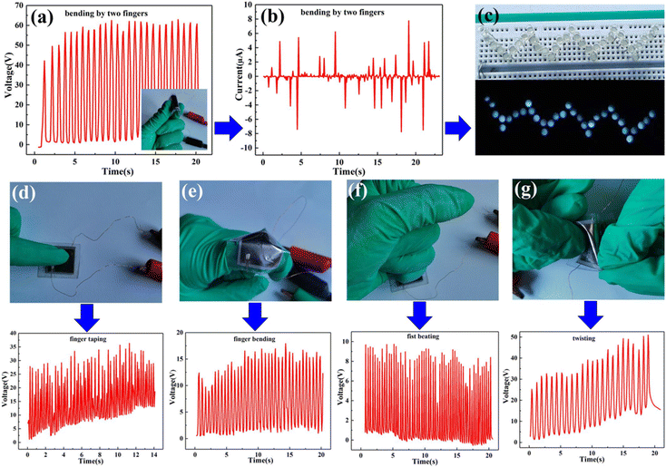 | ||
| Fig. 18 Demonstration of the output performance of a flexible HOG/PZT/P(VDF-TrFE) PENG upon different hand motions. (a) Voltage, (b) current, and (c) glowing of 30 LEDs generated via figure bending; (d)–(g) optical images and voltage outputs from figure tapping, figure bending, pressing, and twisting activities; adapted with permission from ref. 301. Copyright 2021, Elsevier publication. | ||
Chaipanich et al. reported that the PZT ceramic poled at 130 °C with a 10 kV cm−1 field strength for 45 min has a higher d33 value (28 pC N−1) and can be implemented as a smart concrete composite for civil-engineering purposes.302 Eid et al. investigated PZT Portland cement (PZT-POC) samples poled at room temperature with a poling field of 1.5 kV cm−1 for 2 h, and proposed that this composite can act as a smart shield and also explain the variation of the piezoelectric coefficient with the PZT content in PZT-POC.303 Similarly, Costa et al. successfully developed a cost-effective castor-oil-based 1–3 connectivity polyurethane–PZT composite (PUR-PZT) having a d33 value of 246 pC N−1 from optimized poling conditions of 10 kV cm−1 at 100 °C for 60 min, which can be implemented as an acoustic emission (AE) wave sensor in healthcare systems.113 Chen et al. fabricated a soft PZT nanofibre–PENG with dimensions of around 60 nm and 500 μm using poling conditions of 40 kV cm−1, at a poling temperature greater than 140 °C for about 24 h. PZT fibres were positioned over fine platinum electrodes of the integrated structure placed on a silicon substrate. The voltage and power output performance of the fully assembled setup was 1.63 V and 0.03 W, respectively.117 For attaining the highest d33 value, a typical study was conducted by Xu et al.304 on a PT-doped PMN nanowire composite (a PMN–PT-based PENG) for self-power-generating sensing. For an improved outcome, the PMN–PT hierarchical structure was poled in a silicone oil bath with a poling field of 50 kV cm−1 at 150 °C for 24 h, and showed an increased d33 value (∼2500 pm V−1) with a maximum voltage and current of ∼7.8 V and ∼2.29 μA, respectively. The output signal form of PZT and PMN–PT was verified using a dynamic mechanical analyzer (DMA) (Fig. 19).
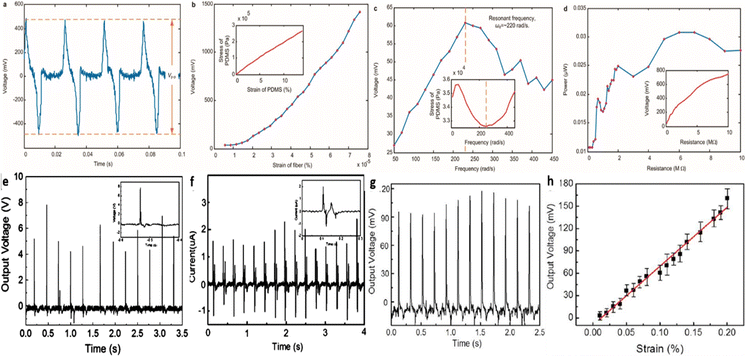 | ||
| Fig. 19 (a) and (b) PZT nanogenerator output voltage with respect to time (a) and % fiber strain(b); (c) voltage with different load frequencies in the polymer matrix; (d) output power against load resistance; reproduced with permission from ref. 117. Copyright 2010, ACS Publication. Voltage (e) and current (f) generation from tapping of the PMN–PT based device with a plastic screwdriver handle; and (g) and (h) mechanical response of the PENG upon the application of cyclic stepwise strain; reprinted with permission from ref. 304. Copyright 2013, ACS Publication. | ||
Recently, Liu et al. fabricated a 4D-printed PZT composite-based acoustic transducer for underwater applications. With poling conditions of 25 kV cm−1, 80 °C and 30 min, the samples showed maximum piezoelectric properties of d33 = 103 pC N−1 and εr = 274.34, respectively.305Fig. 20 illustrates the whole fabrication process and the output characteristics of the PZT composite ultrasonic transducer.
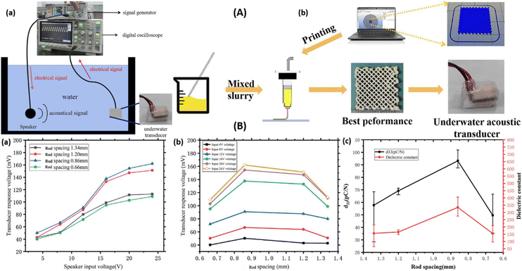 | ||
| Fig. 20 (A) (a) Optical image of the PZT device based underwater acoustic transducer setup. (b) Fabrication of composite film by printing approach along with the suitable mixed slurry. (B) (a) Comparative study of the signal generated input and oscilloscope output, (b) variation of transducer peak-to-peak voltage output with rod spacing, and (c) variation of d33 value and dielectric constant with respect to rod spacing; reproduced with permission from ref. 305. Copyright 2021, IOP publication. | ||
Wang et al. successfully fabricated a flexible PNN–PZT-based high-performance composite device using a direct-write 3D-printing process. The 0–3 composite specimens have a greater piezoelectric voltage coefficient (g33) of 400 × 10−3 V m N−1 after poling it in a high electric field of 100 kV cm−1, at 100 °C for 10 h. The 3D-printed flexible and stretchable PENG can light up 20 red LEDs and can be used in artificial muscles, biology signal identification, and soft robotics. Fig. 21 demonstrates the PENG mechanism, 3D models, simulation results and the output performance of the 3D-printed PNN–PZT device.306 Recently, Kim et al. achieved enhanced piezoelectric properties at lower sintering temperatures through adding CuO to PNN–PZT. CuO–PNN–PZT shows a higher d33 and transduction coefficient of 502 pC N−1 and (d33 × g33) 17![[thin space (1/6-em)]](https://www.rsc.org/images/entities/char_2009.gif) 354 × 10−15 m2 N−1, respectively, at the low sintering temperature of 1025 °C and poling of the composite in the presence of a DC electric field of 30 kV cm−1 for 20 min at 100 °C (Fig. 22).307
354 × 10−15 m2 N−1, respectively, at the low sintering temperature of 1025 °C and poling of the composite in the presence of a DC electric field of 30 kV cm−1 for 20 min at 100 °C (Fig. 22).307
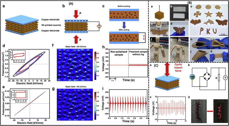 | ||
| Fig. 21 (A) Study of the electromechanical performance of a 3D-printed PNN–PZT composite. (a)–(c) Schematic of the poling process and dipole orientation in PNN–PZT during the on and off conditions of the poling process; (d) and (e) P–E loops at a different electric fields with and without an Ag-coat on the ceramic–polymer composite specimen; (f) and (g) electric field distribution (100 kV cm−1) of the Ag/PNN–PZT and PNN–PZT composites, respectively, using COMSOL simulation software; (h) output voltage before and after the poling process for Ag/PNN–PZT; and (i) voltage output of PNN–PZT after poling, measure using a digital oscilloscope. (B) (a) 3D printing process, (b) image of pure PDMS mat; (c)–(e) different structured printed ceramic-composites; (f) and (g) printed flexible composite fixed to wooden doll before and after hand bending; (h)–(k) flexibility testing of printed composite. (C) (a) Application of force on 3D printed composite; (b) circuit for output measurement; (c) generated open circuit voltage within 15 seconds; and (d) glowing of 20 red LEDs, republished with permission from ref. 306. Copyright Elsevier publications. | ||
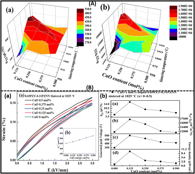 | ||
| Fig. 22 (A) and (B) Fluctuation of the piezoelectric properties with respect to the sintering temperature and CuO dopant percentage in PNN–PZT using a 3D model, S–E loop, and 2D plot. A(a and b) 3D plots of d33 and d33 × g33 with CuO content and sintering temperature. B(a) Deviation of the S–E loop with CuO proportion in the PNN–PZT composite; and (b) variation of the voltage output, d33, d33 × g33, and energy density with CuO doping; reproduced with permission from ref. 307. Copyright Elsevier publications. | ||
Ng et al.308 analysed the PZT–P(VDF-TrFE) composite through a stepwise poled technique for three different situations: ceramic part differently at 70 °C; both the ceramic–polymer in the similar direction; and both phases poled in a reverse direction at 50 °C, E = 100 kV cm−1 for 30 min. The signals produced were verified using the laser-induced pressure pulse (LIPP) method. In a later study Vineet et al.274 investigated 0–3 PZT–PVDF composite structures by varying the PZT percentage in the PVDF matrix. Poled PZT-PVDF films (80 °C, field of 100 kV cm−1 for 24 h) with higher PZT filler ratio enhances the electro-active β-phase content, which results in higher piezoelectric/dielectric performance.
In contrast to PZT and PVDF composite PENGs, Zhong et al. prepared an advanced wearable and flexible polyethylene terephthalate or ethylene-vinyl acetate (PET/EVA) based PENG, which has a higher d33 of ∼6300 pC N−1 and can be operated under adverse environmental conditions such as higher moisture and temperature (∼70 °C). The device was corona poled with a field of 20 kV for 3 min and generated a current of ∼29.6 μA and a power of ∼0.444 mW via conventional hand tapping (Fig. 23).309 Similarly, Karlsson et al.,193 used the periodic poling process to produce the Rubidium Titanyle Phosphate (RbTiOPO4) bulk crystal (dimension of length 3 mm and width 0.7 mm) with high quality domain grating for the improved frequency magnification to generate blue light. Here, the periodic poling process is depends on the electro-optic technique with a high poling voltage of 2.3 kV spotted with a cyclic electrode of 50% repetition cycle, which results the d33 nonlinearity of 12.8 pm V−1.193 Recently Jia et al. fabricated a piezoelectric PZT-epoxy fibre-based high-frequency ultrasonic transducer with a high d33 value of 670 pC N−1, and a comparative study of d33 and g33 with the PZT content confirmed that the d33 value increases and the g33 value decreases with the PZT content.310 Energy-harvesting and self-powering techniques are auspicious and significant investigations. Because of the optimized poling conditions with a higher piezoelectric constant (d33) there has been an incredible development for energy-harvesting materials. In addition, integrating with various advanced materials is of great benefit concerning their translation capacity.
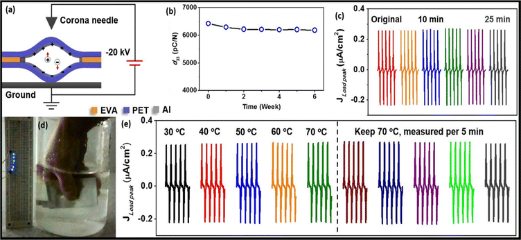 | ||
| Fig. 23 Verification of PET/EVA PENG sample via (a) corona poling, and (b) d33 coefficient consistency over a six-week period; (c) stability of the generator under high moisture conditions; (d) illumination of six LEDs by pressing the device underwater; and (e) current output of the flexible PENG at high temperature (70 °C); reproduced with permission from ref. 309. Copyright 2017, Elsevier publication. | ||
Conclusion and future aspects
This report examined the latest research progress on the poling effect of lead-based and lead-free non-toxic piezoelectric materials and composites. From this, we conclude that the poling procedure and its optimised conditions are probably the best paths for tailoring or enhancing the piezoelectric response in materials. The poling field strength, temperature, time period, dimensions and other numerous factors have shown noteworthy outcomes in the performance of piezoelectric materials and composites. When the supplied electric field is raised towards the saturation point, the direct piezoelectric effect and the piezoelectric strain coefficient d33 increase sharply. Thus, creating a suitable d33 unimorph piezoelectric device will improve energy-harvesting efficiency and will be completely reliant on the appropriate poling conditions. As a result, the current research opens the way for further feasibility of achieving these poling conditions in the form of vibration-based energy harvesters, sensing devices, and vibration controllers. It should be noted that, despite the numerous advantages, optimum poling situations for device functioning and the scientific acceptance of poling parameters is a tedious job; this is because poling techniques depend upon numerous factors such as the filler content, synthesis procedure, poling field, temperature, time, frequency, dimensions of the element, domain orientation, voids, defects, and chemical composition of the materials. So, several investigations have been adopted for complete knowledge of the domain orientation at the microscopic level in the poling process. The in situ monitoring of domain-configuration evolution during ACP appears to be effective for identifying the abnormality of domain-structure modification and identifying the mechanism of enhancement of the piezoelectric properties. Introducing novel and effective poling methods such as self-poling, graded poling, advanced manufacturing technology and computer simulation procedures motivates researchers to shift attention so that piezoelectric materials can be employed in real-life applications.The strategy of this investigation is to establish a complete knowledge of different poling techniques and their impact on the piezoelectric strain coefficient, and specifically in the d33 mode, in order to fabricate enhanced engineered material and device attributes. The experimental outcomes reveal that the electromechanical performance of the material dramatically changes based on the poling parameters. The above findings shed light on the ideal projection of materials and equipment with superior execution, greater efficiency and reduced deterioration through the application of optimized poling procedures.
Conflicts of interest
There are no conflicts to declare.Acknowledgements
The authors would like to acknowledge the Department of Science and Technology (DST), New Delhi, India, for a research funding under the Scheme for Young Scientists & Technologists (Ref. No. SP/YO/2019/1432).References
- S.-G. Kim, S. Priya and I. Kanno, Piezoelectric MEMS for energy harvesting, MRS Bull., 2012, 37(11), 1039–1050 CrossRef CAS.
- J. Fang, et al., Enhanced mechanical energy harvesting using needleless electrospun poly(vinylidene fluoride) nanofibre webs, Energy Environ. Sci., 2013, 6(7), 2196–2202 RSC.
- G. Tang, et al., Development of high performance piezoelectric d33 mode MEMS vibration energy harvester based on PMN–PT single crystal thick film, Sens. Actuators, A, 2014, 205, 150–155 CrossRef CAS.
- J. Liang and W.-H. Liao, Energy flow in piezoelectric energy harvesting systems, Smart Mater. Struct., 2010, 20(1), 015005 CrossRef.
- G. K. Ottman, et al., Adaptive piezoelectric energy harvesting circuit for wireless remote power supply, IEEE Trans. Power Electron., 2002, 17(5), 669–676 Search PubMed.
- Y. Tang, et al., Primary and secondary pyroelectric coefficients of rhombohedral and tetragonal single-domain relaxor-PbTiO3 single crystals, J. Appl. Phys., 2013, 114(8), 084105 CrossRef.
- H. Tao and J. Wu, New poling method for piezoelectric ceramics, J. Mater. Chem. C, 2017, 5(7), 1601–1606 RSC.
- H. Du, et al., An approach to further improve piezoelectric properties of (K0.5Na0.5)NbO3-based lead-free ceramics, Appl. Phys. Lett., 2007, 91(20), 202907 CrossRef.
- L. Luo, X. Zhao and H. Luo, Single Crystal PZN–PT, PMN–PT, PSN–PT, and PIN–PT-Based Piezoelectric Materials, Adv. Piezoelectr. Mater., 2010, 271–318 Search PubMed.
- A. Arnau and D. Soares, Fundamentals of piezoelectricity, Piezoelectric transducers and applications, 2009, Springer, pp. 1–38 Search PubMed.
- H. GuO, et al., Electrical poling below coercive field for large piezoelectricity, Appl. Phys. Lett., 2013, 102, 092902 CrossRef.
- E. Subbarao, et al., Domain switching and microcracking during poling of lead zirconate titanate ceramics, Ferroelectrics, 1993, 145(1), 271–281 CrossRef CAS.
- A. B. Kounga, et al., High-temperature poling of ferroelectrics, J. Appl. Phys., 2008, 104(2), 024116 CrossRef.
- V. Bijalwan, I. Sokolov and P. Tofel, Poling procedures and piezoelectric response of (Ba0.85Ca0.15Zr0.1T0.9)O3 ceramics, J. Asian Ceram. Soc., 2021, 9(1), 229–236 CrossRef.
- G. Fan, Morphotropic phase boundary and piezoelectric properties of (Bi1/2Na1/2)TiO3–(Bi1/2K1/2)TiO3–KNbO3(Bi1/2Na1/2)TiO3–(Bi1/2K1/2)TiO3–KNbO3 lead-free piezoelectric ceramics, Appl. Phys. Lett., 2007, 91, 202908 CrossRef.
- S. Fedosov, et al., Application of corona discharge for poling ferroelectric and nonlinear optical polymers varXiv preprint arXiv:0705.0177.
- A. Hartono, et al., Electric field poling 2 GV m−1 to improve piezoelectricity of PVDF thin film, AIP Conf. Proc., 2016, 1719, 030021 CrossRef.
- W. Jo and J. Rödel, Electric-field-induced volume change and room temperature phase stability of (Bi1/2Na1/2)TiO3−x mol% BaTiO3 piezoceramics, Appl. Phys. Lett., 2011, 99(4), 042901 CrossRef.
- S. R. Anton and H. A. Sodano, A review of power harvesting using piezoelectric materials (2003–2006), Smart Mater. Struct., 2007, 16(3), R1 CrossRef CAS.
- S. P. Beeby, M. J. Tudor and N. White, Energy harvesting vibration sources for microsystems applications, Meas. Sci. Technol., 2006, 17(12), R175 CrossRef CAS.
- T. Ogawa, et al., Giant electromechanical coupling factor of k31 mode and piezoelectric d31 constant in Pb[(Zn1/3Nb2/3)0.91Ti0.09]O3 piezoelectric single crystal, Jpn. J. Appl. Phys., 2002, 41(1A), L55 CrossRef CAS.
- Y. Tan, et al., High-performance textile piezoelectric pressure sensor with novel structural hierarchy based on ZnO nanorods array for wearable application, Nano Res., 2021, 14(11), 3969–3976 CrossRef CAS.
- R. Kiran, et al., Effect of poling orientation on piezoelectric materials operating in longitudinal mode, Mater. Res. Express, 2019, 6(6), 065711 CrossRef CAS.
- S.-B. Kim, et al., Comparison of MEMS PZT cantilevers based on d31 and d33 modes for vibration energy harvesting, J. Microelectromech. Syst., 2012, 22(1), 26–33 Search PubMed.
- Y. Liao and H. A. Sodano, Model of a single mode energy harvester and properties for optimal power generation, Smart Mater. Struct., 2008, 17(6), 065026 CrossRef.
- Y. Yao, et al., Large piezoelectricity and dielectric permittivity in BaTiO3–xBaSnO3 system: the role of phase coexisting, EPL, 2012, 98(2), 27008 CrossRef.
- N. Pertsev, A. Zembilgotov and R. Waser, Aggregate linear properties of ferroelectric ceramics and polycrystalline thin films: calculation by the method of effective piezoelectric medium, J. Appl. Phys., 1998, 84(3), 1524–1529 CrossRef CAS.
- R. Kiran, et al., Deciphering the importance of graded poling in piezoelectric materials: a numerical study, Eng. Rep., 2020, 2(11), e12266 CAS.
- A. Kumar, et al., Optimization of poling parameters of mechanically processed PLZT 8/60/40 ceramics based on dielectric and piezoelectric studies, Eur. Phys. J. B, 2015, 88(11), 1–9 CrossRef.
- M. H. Malakooti and H. A. Sodano, Direct measurement of piezoelectric shear coefficient, J. Appl. Phys., 2013, 113(21), 214106 CrossRef.
- I. Kanno, et al., Evaluation of intrinsic shear piezoelectric coefficient d15 of c-axis oriented Pb(Zr,Ti)O3 films, Appl. Phys. Express, 2009, 2(9), 091402 CrossRef.
- C. Bowen, et al., Optimisation of interdigitated electrodes for piezoelectric actuators and active fibre composites, J. Electroceram., 2006, 16(4), 263–269 CrossRef.
- C. Wang, et al., A Micromachined Piezoelectric Ultrasonic Transducer Operating in d33 Mode Using Square Interdigital Electrodes, IEEE Sens. J., 2007, 7(7), 967–976 Search PubMed.
- M. Stewart and M. G. Cain, Direct piezoelectric measurement: the berlincourt method, Characterisation of Ferroelectric Bulk Materials and Thin Films, 2014, Springer, pp. 37–64 Search PubMed.
- G. Claire, Health monitoring of polymer composite structures using piezoelectric nanofibres, PhDT, Cranfield University, 2017 Search PubMed.
- Y. Qi and M. C. McAlpine, Nanotechnology-enabled flexible and biocompatible energy harvesting, Energy Environ. Sci., 2010, 3(9), 1275–1285 RSC.
- P. Dineva, et al., Piezoelectric materials, Dynamic fracture of piezoelectric materials. 2014, Springer. pp. 7–32 Search PubMed.
- M. K. Adak and D. Dhak, Hysteresis and energy storage properties study of Ba, J. Indian Chem. Soc, 2019, 96, 563–568 CAS.
- S. Sharma, et al., Design of spatially varying electrical poling for enhanced piezoelectricity in Pb(Mg1/3Nb2/3)O3–0.35PbTiO3, Int. J. Mech. Mater. Des., 2021, 17(1), 99–118 CrossRef CAS.
- T. Ng and W. Liao, Sensitivity analysis and energy harvesting for a self-powered piezoelectric sensor, J. Intell. Mater. Syst. Struct., 2005, 16(10), 785–797 CrossRef.
- J. Sun, et al., Morphing aircraft based on smart materials and structures: a state-of-the-art review, J. Intell. Mater. Syst. Struct., 2016, 27(17), 2289–2312 CrossRef CAS.
- A. Q. Jiang and Y. Zhang, Next-generation ferroelectric domain-wall memories: principle and architecture, NPG Asia Mater., 2019, 11(1), 1–5 CrossRef.
- J. Li, et al., Domain switching in polycrystalline ferroelectric ceramics, Nat. Mater., 2005, 4(10), 776–781 CrossRef CAS PubMed.
- G. Viola, et al., Contribution of piezoelectric effect, electrostriction and ferroelectric/ferroelastic switching to strain–electric field response of dielectrics, J. Adv. Dielectr., 2013, 3(01), 1350007 CrossRef.
- D. Damjanovic, Ferroelectric, dielectric and piezoelectric properties of ferroelectric thin films and ceramics, Rep. Prog. Phys., 1998, 61(9), 1267 CrossRef CAS.
- D. Damjanovic, Chapter 4-Hysteresis in Piezoelectric and Ferroelectric Materials, Sci. Hysteresis, 2006, 3, 337–465 Search PubMed.
- T. W. Cornelius, et al., Piezoelectric response and electrical properties of Pb(Zr1−xTix)O3 thin films: the role of imprint and composition, J. Appl. Phys., 2017, 122(16), 164104 CrossRef.
- C. Park, et al., In situ poling and imidization of amorphous piezoelectric polyimides, Polymer, 2004, 45(16), 5417–5425 CrossRef CAS.
- N. Bhardwaj and S. C. Kundu, Electrospinning: a fascinating fiber fabrication technique, Biotechnol. Adv., 2010, 28(3), 325–347 CrossRef CAS PubMed.
- I. Tanahashi, et al., Optical nonlinearities of Au/SiO2 composite thin films prepared by a sputtering method, J. Appl. Phys., 1996, 79(3), 1244–1249 CrossRef CAS.
- G. D. Jones, et al., Characterization, performance and optimization of PVDF as a piezoelectric film for advanced space mirror concepts. 2005, Citeseer Search PubMed.
- M. Duggina and N. Jackson, Converting Parylene C into a Thin Film Piezoelectric Material, 2021 IEEE 16th Nanotechnology Materials and Devices Conference (NMDC), 2021, IEEE.
- C. Li, et al., Flexible dome and bump shape piezoelectric tactile sensors using PVDF–TrFE copolymer, J. Microelectromech. Syst., 2008, 17(2), 334–341 CAS.
- H. Kim, et al., Increased piezoelectric response in functional nanocomposites through multiwall carbon nanotube interface and fused-deposition modeling three-dimensional printing, MRS Commun., 2017, 7(4), 960–966 CrossRef CAS.
- C. Groner and M. Hirsh, Comparison of poling techniques for inducing piezoelectric behavior in PVF2, 1985 5th International Symposium on Electrets (ISE 5), IEEE, 1985, pp. 912–917 Search PubMed.
- Z. Weinberg, W. Johnson and M. Lampert, High-field transport in SiO2 on silicon induced by corona charging of the unmetallized surface, J. Appl. Phys., 1976, 47(1), 248–255 CrossRef CAS.
- K. S. Ramadan, D. Sameoto and S. Evoy, A review of piezoelectric polymers as functional materials for electromechanical transducers, Smart Mater. Struct., 2014, 23(3), 033001 CrossRef CAS.
- N. Yamamoto, Y. Yamashita and Y. Hosono, et al., Ultrasonic probe, piezoelectric transducer, method of manufacturing ultrasonic probe, and method of manufacturing piezoelectric transducer. U.S. Patent 9966524, 2018 Search PubMed.
- Y. Yamashita, N. Yamamoto and Y. Hosono, et al., Piezoelectric transducer, ultrasonic probe, and piezoelectric transducer manufacturing method. U.S. Patent 9972766, 2018 Search PubMed.
- J. Liu, et al., Impact of alternating current electric field poling on piezoelectric and dielectric properties of Pb(In1/2Nb1/2)O3–Pb(Mg1/3Nb2/3)O3–PbTiO3 ferroelectric crystals, J. Appl. Phys., 2020, 128(9), 094104 CrossRef CAS.
- L. Jin, F. Li and S. Zhang, Decoding the fingerprint of ferroelectric loops: comprehension of the material properties and structures, Progress in Advanced Dielectrics, 2020, World Scientific, pp. 21–104 Search PubMed.
- W.-Y. Chang, et al., Dielectric and piezoelectric properties of 0.7Pb(Mg1/3Nb2/3)O3–0.3PbTiO3 single crystal poled using alternating current, Mater. Res. Lett., 2018, 6(10), 537–544 CrossRef CAS.
- J. Xu, et al., Piezoelectric performance enhancement of Pb(Mg1/3Nb2/3)O3–0.25PbTiO3 crystals by alternating current polarization for ultrasonic transducer, Appl. Phys. Lett., 2018, 112(18), 182901 CrossRef.
- C. Qiu, et al., Thickness dependence of dielectric and piezoelectric properties for alternating current electric–field-poled relaxor-PbTiO3 crystals, J. Appl. Phys., 2019, 125(1), 014102 CrossRef.
- C. He, et al., Dielectric and piezoelectric properties of Pb[(Mg1/3Nb2/3)0.52(Yb1/2Nb1/2)0.15Ti0.33]O3 single-crystal rectangular plate and beam mode transducers poled by alternate current poling, Jpn. J. Appl. Phys., 2019, 58(SL), SLLD06 CrossRef CAS.
- C. Qiu, et al., Transparent ferroelectric crystals with ultrahigh piezoelectricity, Nature, 2020, 577(7790), 350–354 CrossRef CAS PubMed.
- C. Luo, et al., High temperature and low voltage AC poling for 0.24Pb(In1/2Nb1/2)O3-0.46Pb(Mg1/3Nb2/3)O3–0.30PbTiO3 piezoelectric single crystals manufactured by continuous-feeding Bridgman method, J. Materiomics, 2021, 7(3), 621–628 CrossRef.
- Y. Sun, et al., Spurious-mode vibrations caused by alternating current poling and their solution process for Pb(Mg1/3Nb2/3)O3–0.30PbTiO3 single crystals, J. Materiomics, 2022, 8(1), 96–103 CrossRef.
- B. Gross, et al., Electron-beam poling of piezoelectric polymer electrets, J. Appl. Phys., 1987, 62(4), 1429–1432 CrossRef CAS.
- Y. Glickman, et al., Electron-beam-induced domain poling in LiNbO3 for two-dimensional nonlinear frequency conversion, Appl. Phys. Lett., 2006, 88(1), 011103 CrossRef.
- K. A. Mirica, et al., Mechanical drawing of gas sensors on paper, Angew. Chem., 2012, 124(43), 10898–10903 CrossRef.
- H. Asai, et al., Effect of melt and solution electrospinning on the formation and structure of poly(vinylidene fluoride) fibres, RSC Adv., 2017, 7(29), 17593–17598 RSC.
- P. D. Dalton, et al., Electrospinning and additive manufacturing: converging technologies, Biomater. Sci., 2013, 1(2), 171–185 RSC.
- B. Zaarour, L. Zhu and X. Jin, Direct fabrication of electrospun branched nanofibers with tiny diameters for oil absorption, J. Dispersion Sci. Technol., 2021, 42(14), 2085–2091 CrossRef CAS.
- F. Carpi, Electromechanically active polymers: a concise reference, 2016, Springer Search PubMed.
- P. Martins, A. C. Lopes and S. Lanceros-Mendez, Electroactive phases of poly(vinylidene fluoride): determination, processing and applications, Prog. Polym. Sci., 2014, 39, 683–706 CrossRef CAS.
- G. Haertling and C. Land, Recent improvements in the optical and electrooptic properties of PLZT ceramics, Ferroelectrics, 1972, 3(1), 269–280 CrossRef CAS.
- A. Kumar, et al., Ultra high strain properties of lanthanum substituted PZT electro-ceramics prepared via mechanical activation, J. Alloys Compd., 2014, 599, 53–59 CrossRef CAS.
- A. James, M. L. V. Mahesh and V. V. Bhanu Prasad, J. Mater. Sci.: Mater. Electron., 2013, 24, 4684–4692 CrossRef.
- Y. Wan, et al., Phase transition characteristics of the relaxor-based 0.24PIN–0.51PMN–0.25PT single crystals, J. Alloys Compd., 2013, 558, 244–247 CrossRef CAS.
- T. Liu, et al., Analysis of PZT/PVDF composites performance reinforced by aramid fibers, Mater. Res. Express, 2019, 6(6), 066303 CrossRef CAS.
- A. B. K. Njiwa, et al., Influence of radial stress on the poling behaviour of lead zirconate titanate ceramics, Acta Mater., 2007, 55(2), 675–680 CrossRef.
- H. Du, et al., Effect of poling condition on piezoelectric properties of (K0.5Na0.5)NbO3–LiNbO3 lead-free piezoelectric ceramics, Mater. Sci. Eng., B, 2007, 137(1–3), 175–179 CrossRef CAS.
- E. Chandrakala, J. P. Praveen and D. Das, Effect of poling process on piezoelectric properties of BCZT–0.08 wt% CeO2 lead-free ceramics, AIP Conference Proceedings, 2016. AIP Publishing LLC Search PubMed.
- H.-L. Du, et al., Effect of poling condition on piezoelectric properties of (K0.5Na0.5)NbO3 ceramics, Trans. Nonferrous Met. Soc. China, 2006, 16, s462–s465 CrossRef.
- H. Kim, et al., Integrated 3D printing and corona poling process of PVDF piezoelectric films for pressure sensor application, Smart Mater. Struct., 2017, 26(8), 085027 CrossRef.
- D. A. Porter, T. V. Hoang and T. A. Berfield, Effects of in-situ poling and process parameters on fused filament fabrication printed PVDF sheet mechanical and electrical properties, Addit. Manuf., 2017, 13, 81–92 CAS.
- R. Tao, et al., Fused filament fabrication of PVDF films for piezoelectric sensing and energy harvesting applications, Mater. Adv., 2022, 3, 4851–4860 RSC.
- H. Tao, et al., Poling temperature-insensitive piezoelectric constant of high-performance potassium sodium niobate piezoceramics, J. Am. Ceram. Soc., 2020, 103(8), 4402–4410 CrossRef CAS.
- H. Tao, et al., Ultrahigh performance in lead-free piezoceramics utilizing a relaxor slush polar state with multiphase coexistence, J. Am. Ceram. Soc., 2019, 141(35), 13987–13994 CAS.
- Y. Huan, et al., Effect of poling temperature on piezoelectric coefficient in (Na0.52K0.4425Li0.0375)(Nb0.86Ta0.06Sb0.08)O3 ceramics, Phys. Status Solidi A, 2013, 210(12), 2579–2582 CrossRef CAS.
- J. Rödel, et al., Perspective on the development of lead-free piezoceramics, J. Am. Ceram. Soc., 2009, 92(6), 1153–1177 CrossRef.
- P. Panda, Environmental friendly lead-free piezoelectric materials, J. Mater. Sci., 2009, 44(19), 5049–5062 CrossRef CAS.
- T. R. Shrout and S. J. Zhang, Lead-free piezoelectric ceramics: alternatives for PZT?, J. Electroceram., 2007, 19(1), 113–126 CrossRef.
- D. Damjanovic, et al., What can be expected from lead-free piezoelectric materials?, Funct. Mater. Lett., 2010, 3(01), 5–13 CrossRef CAS.
- S. Yoshikawa, Pb(ZrTi)O3 [PZT] fibers: Fabrication and measurement methods, J. Intell. Mater. Syst. Struct., 1995, 6(2), 152–158 CrossRef CAS.
- A. Safari and V. F. Janas, Processing of fine-scale piezoelectric ceramic/polymer composites for transducer applications, Ferroelectrics, 1997, 196(1), 187–190 CrossRef CAS.
- R. J. Meyer Jr, High-frequency (15–70 MHz) 1–3 PZT fiber/polymer composites: fabrication and characterization, PhDT, 1998, The Pennsylvania State University Search PubMed.
- D. Sporn, et al., Smart structures by integrated piezoelectric thin fibers, Piezoelectric Materials: Advances in Science, Technology and Applications, Springer, 2000, vol. 76, pp. 87–97 Search PubMed.
- R. Steinhausen, et al., Properties of fine scale piezoelectric PZT fibers with different Zr content, J. Eur. Ceram. Soc., 2001, 21(10–11), 1459–1462 CrossRef CAS.
- R. Steinhausen, et al., Finescaled piezoelectric 1–3 composites: properties and modeling, J. Eur. Ceram. Soc., 1999, 19(6–7), 1289–1293 CrossRef CAS.
- K. Li, et al., Studies of Li, Nb and Mn doped PZT ceramic fibers and ceramic fiber/epoxy 1–3 composites, PRICM 4: Forth Pacific Rim International Conference on Advanced Materials and Processing, Vols I and II, Japan Institute Metals, Honolulu, HI, 2001, pp. 1583–1586 Search PubMed.
- K. Li, H. L.-W. Chan and C.-L. Choy, Study of Zinc and Niobium Modified Lead Zirconate Titanate Fiber/Epoxy 1–3 Composites, Jpn. J. Appl. Phys., 2002, 41(11S), 6989 CrossRef CAS.
- S. Yoshikawa, et al., Piezoelectric PZT tubes and fibers for passive vibrational damping, in ISAF'92: Proceedings of the Eighth IEEE International Symposium on Applications of Ferroelectrics, IEEE, 1992, pp. 269–272.
- A. D. Prewitt and J. L. Jones, Effects of the poling process on piezoelectric properties in lead zirconate titanate ceramics, Ferroelectrics, 2011, 419(1), 39–45 CrossRef CAS.
- N. Jaitanong and A. Chaipanich, Effect of poling temperature on piezoelectric properties of 0–3 PZT-Portland cement composites, Ferroelectr., Lett. Sect., 2008, 35(1–2), 17–23 CrossRef CAS.
- H. Shifeng, et al., Poling process and piezoelectric properties of lead zirconate titanate/sulphoaluminate cement composites, J. Mater. Sci., 2004, 39(23), 6975–6979 CrossRef.
- J. Nuffer, D. Lupascu and J. Rödel, Damage evolution in ferroelectric PZT induced by bipolar electric cycling, Acta Mater., 2000, 48(14), 3783–3794 CrossRef CAS.
- Y. Guo, et al., Effect of composition and poling field on the properties and ferroelectric phase-stability of Pb(Mg1/3Nb2/3)O3–PbTiO3 crystals, J. Appl. Phys., 2002, 92(10), 6134–6138 CrossRef CAS.
- L. Bian, et al., High-performance [001] c-textured PNN–PZT relaxor ferroelectric ceramics for electromechanical coupling devices, Adv. Funct. Mater., 2020, 30(25), 2001846 CrossRef CAS.
- D. V. Taylor and D. Damjanovic, Piezoelectric properties of rhombohedral Pb(Zr,Ti)O3 thin films with (100), (111), and “random” crystallographic orientation, Appl. Phys. Lett., 2000, 76(12), 1615–1617 CrossRef CAS.
- M. Alguero, et al., Degradation of the d33 piezoelectric coefficient for PZT ceramics under static and cyclic compressive loading, J. Eur. Ceram. Soc., 2001, 21(10–11), 1437–1440 CrossRef CAS.
- J. G. L. Costa, et al., 1–3 Castor Oil-Based Polyurethane/PZT Piezoelectric Composite as a Possible Candidate for Structural Health Monitoring, Mater. Res., 2020, 23(5), e20200205 CrossRef CAS.
- D. Damjanovic, et al., Monodomain versus polydomain piezoelectric response of 0.67Pb(Mg1/3Nb2/3)O3–0.33PbTiO3 single crystals along nonpolar directions, Appl. Phys. Lett., 2003, 83(3), 527–529 CrossRef CAS.
- Z. Xu, et al., Strain anisotropy and piezoelectric response along 〈001〉 and 〈110〉 directions in PMN–38PT single crystal, Mater. Lett., 2005, 59(13), 1653–1655 CrossRef CAS.
- Y. Yamashita and Y. Hosono, High Curie temperature piezoelectric single crystals of the Pb(In1/2Nb1/2)O3–Pb(Mg1/3Nb2/3)O3–0.30PbTiO3 ternary materials system, Handb. Adv. Dielectr., Piezoelectr. Ferroelectr. Mater., 2008, 205–231 CAS.
- X. Chen, et al., 1.6 V nanogenerator for mechanical energy harvesting using PZT nanofibers, Nano Lett., 2010, 10(6), 2133–2137 CrossRef CAS PubMed.
- J. H. Liao, et al., Microstructure and properties of modified PbTiO3 ceramics, Ferroelectrics, 1992, 127(1), 101–106 CrossRef.
- M. Marsilius, T. Granzow and J. L. Jones, Effect of electrical and mechanical poling history on domain orientation and piezoelectric properties of soft and hard PZT ceramics, Sci. Technol. Adv. Mater., 2011, 12(1), 015002 CrossRef PubMed.
- W. Wu, et al., Lead zirconate titanate nanowire textile nanogenerator for wearable energy-harvesting and self-powered devices, ACS Nano, 2012, 6(7), 6231–6235 CrossRef CAS PubMed.
- N. Cui, et al., Magnetic force driven nanogenerators as a noncontact energy harvester and sensor, Nano Lett., 2012, 12(7), 3701–3705 CrossRef CAS PubMed.
- J. Khaliq, et al., Effect of the piezoelectric ceramic filler dielectric constant on the piezoelectric properties of PZT-epoxy composites, Ceram. Int., 2017, 43(2), 2774–2779 CrossRef CAS.
- D. Kuscer, et al., Integrated piezoelectric vibration system for fouling mitigation in ceramic filtration membranes, J. Membr. Sci., 2017, 540, 277–284 CrossRef CAS.
- F. Eichhorn, et al., Porous piezoelectric ceramics with 3-3-connectivity fabricated by impregnation of cellulose paper structures, Mater. Lett., 2017, 206, 158–161 CrossRef CAS.
- C. Huang, et al., Effect of preparation process on properties of PLZT (9/65/35) transparent ceramics, J. Alloys Compd., 2017, 723, 602–610 CrossRef CAS.
- X. Luo, et al., Dielectric, ferroelectric and piezoelectric properties of MnO2-doped Pb(Yb1/2Nb1/2)O3–Pb(Zr,Ti)O3 ceramics, Ceram. Int., 2018, 44(7), 8456–8460 CrossRef CAS.
- V. Kalem, W. Y. Shih and W.-H. Shih, Dielectric and piezoelectric properties of PMN–PT ceramics doped with strontium, Ceram. Int., 2018, 44(3), 2835–2842 CrossRef CAS.
- R. Zhu, et al., Enhancing piezoelectric properties of high-Curie temperature PMN–PH–PT piezoelectric ceramics by citrate method, J. Alloys Compd., 2018, 735, 496–509 CrossRef CAS.
- A. Tawfik, et al., High piezoelectric properties of modified nano lead titanate zirconate ceramics, Mater. Chem. Phys., 2018, 211, 1–8 CrossRef CAS.
- E. Mensur-Alkoy, et al., Mechanical and electromechanical properties of piezoelectric ceramic fibers drawn by the alginate gelation method, Int. J. Appl. Ceram. Technol., 2020, 17(3), 1371–1381 CrossRef CAS.
- K. K. Sappati and S. Bhadra, Flexible piezoelectric 0–3 PZT-PDMS thin film for tactile sensing, IEEE Sens. J., 2020, 20(9), 4610–4617 CAS.
- Y. Yan, et al., Improving piezoelectric properties of Pb(Ni,Nb)O3–Pb(Hf,Ti)O3 ceramics by LiF addition, Ceram. Int., 2018, 44(5), 5790–5793 CrossRef CAS.
- C. Dagdeviren, et al., Conformal piezoelectric energy harvesting and storage from motions of the heart, lung, and diaphragm, Proc. Natl. Acad. Sci. U. S. A., 2014, 111(5), 1927–1932 CrossRef CAS PubMed.
- B. Lu, et al., Ultra-flexible piezoelectric devices integrated with heart to harvest the biomechanical energy, Sci. Rep., 2015, 5(1), 1–9 Search PubMed.
- S. Liu, et al., Transfer-free PZT thin films for flexible Nanogenerators derived from a single-step modified sol–gel process on 2D mica, ACS Appl. Mater. Interfaces, 2020, 12(49), 54991–54999 CrossRef CAS PubMed.
- E. JungáLee, T. YunáKim and S. YeonáLee, High-performance piezoelectric nanogenerators based on chemically-reinforced composites, Energy Environ. Sci., 2018, 11(6), 1425–1430 RSC.
- K. I. Park, et al., Highly-efficient, flexible piezoelectric PZT thin film nanogenerator on plastic substrates, Adv. Mater., 2014, 26(16), 2514–2520 CrossRef CAS PubMed.
- P. Panda, et al., High d33 Lead-Free Piezoceramics: A Review, J. Electron. Mater., 2022, 51, 938–952 CrossRef CAS.
- J. H. Jung, et al., Lead-free NaNbO3 nanowires for a high output piezoelectric nanogenerator, ACS Nano, 2011, 5(12), 10041–10046 CrossRef CAS PubMed.
- J. Liu, et al., Flexible and lead-free piezoelectric nanogenerator as self-powered sensor based on electrospinning BZT–BCT/P(VDF-TrFE) nanofibers, Sens. Actuators, A, 2020, 303, 111796 CrossRef CAS.
- E. L. Tsege, et al., A flexible lead-free piezoelectric nanogenerator based on vertically aligned BaTiO3 nanotube arrays on a Ti-mesh substrate, RSC Adv., 2016, 6(84), 81426–81435 RSC.
- N. P. M. J. Raj, et al., Lead-free piezoelectric nanogenerator using lightweight composite films for harnessing biomechanical energy, Composites, Part B, 2019, 161, 608–616 CrossRef.
- M. Sahu, et al., Piezoelectric nanogenerator based on lead-free flexible PVDF-barium titanate composite films for driving low power electronics, Crystals, 2021, 11(2), 85 CrossRef CAS.
- Z. Hanani, et al., Lead-free nanocomposite piezoelectric nanogenerator film for biomechanical energy harvesting, Nano Energy, 2021, 81, 105661 CrossRef CAS.
- M. Mahesh, V. Bhanu Prasad and A. James, Effect of sintering temperature on the microstructure and electrical properties of zirconium doped barium titanate ceramics, J. Mater. Sci.: Mater. Electron., 2013, 24(12), 4684–4692 CrossRef CAS.
- J. Gao, et al., Recent progress on BaTiO3-based piezoelectric ceramics for actuator applications, Actuators, 2017, 6, 24 CrossRef.
- K.-i Kakimoto, K. Fukata and H. Ogawa, Fabrication of fibrous BaTiO3-reinforced PVDF composite sheet for transducer application, Sens. Actuators, A, 2013, 200, 21–25 CrossRef CAS.
- F. Wang, et al., High quality barium titanate nanofibers for flexible piezoelectric device applications, Sens. Actuators, A, 2015, 233, 195–201 CrossRef CAS.
- L. Dong, D. S. Stone and R. S. Lakes, Enhanced dielectric and piezoelectric properties of xBaZrO3–(1 − x)BaTiO3 ceramics, J. Appl. Phys., 2012, 111(8), 084107 CrossRef.
- S. Shao, et al., High piezoelectric properties and domain configuration in BaTiO3 ceramics obtained through the solid-state reaction route, J. Phys. D: Appl. Phys., 2008, 41(12), 125408 CrossRef.
- A. K. Kalyani, et al., Orthorhombic-tetragonal phase coexistence and enhanced piezo-response at room temperature in Zr, Sn, and Hf modified BaTiO3, Appl. Phys. Lett., 2014, 104(25), 252906 CrossRef.
- W. Liu and X. Ren, Large piezoelectric effect in Pb-free ceramics, Phys. Rev. Lett., 2009, 103(25), 257602 CrossRef PubMed.
- M. Deluca, et al., High-field dielectric properties and Raman spectroscopic investigation of the ferroelectric-to-relaxor crossover in BaSnxTi1−xO3 ceramics, J. Appl. Phys., 2012, 111(8), 084102 CrossRef.
- A. Z. Simoes, et al., Ferroelectric and piezoelectric properties of bismuth titanate thin films grown on different bottom electrodes by soft chemical solution and microwave annealing, Mater. Res. Bull., 2007, 42, 975–981 CrossRef CAS.
- L.-F. Zhu, et al., High piezoelectricity of BaTiO3–CaTiO3–BaSnO3 lead-free ceramics, J. Mater. Chem. C, 2014, 2(24), 4764–4771 RSC.
- M. Mahesh, V. B. Prasad and A. James, Enhanced dielectric and ferroelectric properties of lead-free Ba(Zr0.15Ti0.85)O3 ceramics compacted by cold isostatic pressing, J. Alloys Compd., 2014, 611, 43–49 CrossRef CAS.
- Z.-Y. Shen and J.-F. Li, Enhancement of piezoelectric constant d33 in BaTiO3 ceramics due to nano-domain structure, J. Ceram. Soc. Jpn., 2010, 118(1382), 940–943 CrossRef CAS.
- X. N. Zhu, W. Zhang and X. M. Chen, Enhanced dielectric and ferroelectric characteristics in Ca-modified BaTiO3 ceramics, Aip Adv., 2013, 3(8), 082125 CrossRef.
- W. Xiaoyong, F. Yujun and Y. Xi, Dielectric relaxation behavior in barium stannate titanate ferroelectric ceramics with diffused phase transition, Appl. Phys. Lett., 2003, 83(10), 2031–2033 CrossRef.
- S. Lu, Z. Xu and H. Chen, Tunability and relaxor properties of ferroelectric barium stannate titanate ceramics, Appl. Phys. Lett., 2004, 85(22), 5319–5321 CrossRef CAS.
- K. C. Singh, et al., Structural, electrical and piezoelectric properties of nanocrystalline tin-substituted barium titanate ceramics, J. Alloys Compd., 2011, 509(5), 2597–2601 CrossRef CAS.
- W. Cai, et al., Microstructure, dielectric properties and diffuse phase transition of barium stannate titanate ceramics, J. Mater. Sci.: Mater. Electron., 2011, 22(3), 265–272 CrossRef CAS.
- N. Horchidan, et al., Multiscale study of ferroelectric–relaxor crossover in BaSnxTi1−xO3 ceramics, J. Eur. Ceram. Soc., 2014, 34(15), 3661–3674 CrossRef CAS.
- N. Yasuda, H. O. H. Ohwa and S. A. S. Asano, Dielectric properties and phase transitions of Ba(Ti1−xSnx)O3 solid solution, Jpn. J. Appl. Phys., 1996, 35(9S), 5099 CrossRef CAS.
- W. Cook and H. Jaffe, Ferroelectric and piezoelectric materials, Digest of Literature on Dielectrics, IEEE, 1964, vol. 28, pp. 179–230 Search PubMed.
- B. G. Baraskar, et al., BaTiO3-based lead-free electroceramics with their ferroelectric and piezoelectric properties tuned by Ca2+, Sn4+ and Zr4+ substitution useful for electrostrictive device application, Ferroelectr. Their Appl., 2018, 113–132 CAS.
- P. Zheng, et al., Grain-size effects on dielectric and piezoelectric properties of poled BaTiO3 ceramics, Acta Mater., 2012, 60(13–14), 5022–5030 CrossRef CAS.
- S. Su, et al., Poling dependence and stability of piezoelectric properties of Ba(Zr0.2Ti0.8)O3–(Ba0.7Ca0.3)TiO3 ceramics with huge piezoelectric coefficients, Curr. Appl. Phys., 2011, 11(3), S120–S123 CrossRef.
- J. Mayamae, et al., High piezoelectric response in lead free 0.9BaTiO3–(0.1 − x)CaTiO3–xBaSnO3 solid solution, Ceram. Int., 2017, 43, S121–S128 CrossRef CAS.
- Z.-h Chen, et al., Y2O3 doped Ba0.9Ca0.1Ti0.9Sn0.1O3 ceramics with improved piezoelectric properties, J. Eur. Ceram. Soc., 2018, 38(4), 1349–1355 CrossRef CAS.
- G. d'Ambrogio, et al., Structuring BaTiO3/PDMS nanocomposite via dielectrophoresis for fractional flow reserve measurement, Adv. Eng. Mater., 2021, 23(10), 2100341 CrossRef.
- S. Sharma, et al., NOx Sensing properties of Barium Titanate thin films, Proc. Eng., 2014, 87, 1067–1070 CrossRef CAS.
- H. Shokrollahi, F. Salimi and A. Doostmohammadi, The fabrication and characterization of barium titanate/akermanite nano-bio-ceramic with a suitable piezoelectric coefficient for bone defect recovery, J. Mech. Behav. Biomed. Mater., 2017, 74, 365–370 CrossRef CAS PubMed.
- S. Priya, et al., Recent advances in piezoelectric and magnetoelectric materials phenomena, in Composite Magnetoelectrics, ed. G. Srinivasan, S. Priya and N. X. Sun, Woodhead Publishing, 2015, pp. 103–157 Search PubMed.
- W. Li, et al., High piezoelectric d33 coefficient of lead-free (Ba0.93Ca0.07)(Ti0.95Zr0.05)O3 ceramics sintered at optimal temperature, Mater. Sci. Eng., B, 2011, 176(1), 65–67 CrossRef CAS.
- W. Li, et al., High piezoelectric d33 coefficient in (Ba1−xCax)(Ti0.98Zr0.02)O3 lead-free ceramics with relative high Curie temperature, Mater. Lett., 2010, 64(21), 2325–2327 CrossRef CAS.
- A. Jain, A. K. Panwar and A. Jha, Significant improvement in morphological, dielectric, ferroelectric and piezoelectric characteristics of Ba0.9Sr0.1Ti0.9Zr0.1O3–BaNb2O6 nanocomposites, J. Mater. Sci.: Mater. Electron., 2018, 29(22), 19086–19098 CrossRef CAS.
- J.-P. Ma, et al., Microstructure, dielectric, piezoelectric, and ferroelectric properties of fine-grained 0.94Na0.5Bi0.5TiO3–0.06BaTiO3 ceramics, J. Eur. Ceram. Soc., 2019, 39(2–3), 264–268 CrossRef CAS.
- W. Bai, et al., Electromechanical response and piezoelectric properties in (Ba0.85Ca0.15)(Zr0.1Ti0.9)O3 piezoceramics using nano-sized AlN modification, Ceram. Int., 2018, 44(13), 16040–16050 CrossRef CAS.
- D.-J. Shin, J. Kim and J.-H. Koh, Piezoelectric properties of (1 − x)BZT–xBCT system for energy harvesting applications, J. Eur. Ceram. Soc., 2018, 38(13), 4395–4403 CrossRef CAS.
- M. Zhou, et al., Enhanced Curie temperature and piezoelectric properties of (Ba0.85Ca0.15)(Zr0.10Ti0.90)O3 lead-free ceramics after the addition of LiTaO3, Mater. Res. Bull., 2018, 106, 213–219 CrossRef CAS.
- E. W. Yap, et al., Effect of porosity on the ferroelectric and piezoelectric properties of (Ba0.85Ca0.15)(Zr0.1Ti0.9)O3 piezoelectric ceramics, Scr. Mater., 2018, 145, 122–125 CrossRef CAS.
- X. Ren, Large electric-field-induced strain in ferroelectric crystals by point-defect-mediated reversible domain switching, Nat. Mater., 2004, 3(2), 91–94 CrossRef CAS PubMed.
- D. Xu, et al., Role of A-and B-site excess doping on the improvement of the piezoelectric properties of BaTiO3 lead-free piezoceramics, J. Mater. Sci.: Mater. Electron., 2020, 31(10), 7831–7838 CrossRef CAS.
- C. M. Fancher, J. E. Blendell and K. J. Bowman, Poling effect on d33 in textured Bi0.5Na0.5TiO3-based materials, Scr. Mater., 2013, 68(7), 443–446 CrossRef CAS.
- J. Camargo, et al., Piezoelectric and structural properties of bismuth sodium potassium titanate lead-free ceramics for energy harvesting, J. Mater. Sci.: Mater. Electron., 2021, 32(14), 19117–19125 CrossRef CAS.
- Y. Saito and H. Takao, Synthesis of plate-like (Bi0.5Na0.5)TiO3 particles by using a topochemical microcrystal conversion method and grain-oriented ceramics, J. Korean Phys. Soc., 2007, 51(9), 790–797 CrossRef CAS.
- J. Zeng, et al., Plate-like Na0.5Bi0.5TiO3 template synthesized by a topochemical method, J. Am. Ceram. Soc., 2006, 89(12), 3850–3853 CrossRef CAS.
- X. Wang, et al., Dielectric behavior and microstructure of (Bi1/2Na1/2)TiO3–(Bi1/2K1/2)TiO3–BaTiO3 lead-free piezoelectric ceramics, J. Appl. Phys., 2005, 97(10), 104101 CrossRef.
- S. Choy, et al., Study of compressive type accelerometer based on lead-free BNKBT piezoceramics, Appl. Phys. A, 2006, 82(4), 715–718 CrossRef CAS.
- Y.-R. Zhang, et al., Piezoelectric and ferroelectric properties of Bi-compensated (Bi1/2Na1/2)TiO3–(Bi1/2K1/2)TiO3 lead-free piezoelectric ceramics, J. Appl. Phys., 2008, 103(7), 074109 CrossRef.
- Y. Li, et al., Piezoelectric and dielectric properties of CeO2-doped Bi0.5Na0.44K0.06TiO3 lead-free ceramics, Ceram. Int., 2007, 33(1), 95–99 CrossRef CAS.
- H. Karlsson, F. Laurell and L. Cheng, Periodic poling of RbTiOPO4 for quasi-phase matched blue light generation, Appl. Phys. Lett., 1999, 74(11), 1519–1521 CrossRef CAS.
- C. Zhou, et al., Dielectric and piezoelectric properties of Bi0.5Na0.5TiO3–Bi0.5K0.5TiO3–BiCrO3 lead-free piezoelectric ceramics, J. Alloys Compd., 2009, 478(1–2), 381–385 CrossRef CAS.
- D. Lin, et al., Piezoelectric and ferroelectric properties of [Bi0.5(Na1−x−yKxLiy)0.5]TiO3 lead-free piezoelectric ceramics, Appl. Phys. Lett., 2006, 88(6), 062901 CrossRef.
- H. Nagata, et al., Piezoelectric properties of bismuth sodium titanate ceramics, Dev. Dielectr. Mater. Electron. Dev., 2012, 167, 213–221 Search PubMed.
- S. Li, et al., Piezoelectricity and flexoelectricity of sodium bismuth titanate-based ceramics, Ceram. Int., 2020, 46(2), 2049–2054 CrossRef CAS.
- T. Takeuchi, T. Tani and Y. Saito, Piezoelectric properties of bismuth layer-structured ferroelectric ceramics with a preferred orientation processed by the reactive templated grain growth method, Jpn. J. Appl. Phys., 1999, 38(9S), 5553 CrossRef CAS.
- Y. Saito, et al., Lead-free piezoceramics, Nature, 2004, 432(7013), 84–87 CrossRef CAS PubMed.
- J. F. Li, et al., (K,Na)NbO3-Based Lead-Free Piezoceramics: Fundamental Aspects, Processing Technologies, and Remaining Challenges, J. Am. Ceram. Soc., 2013, 96(12), 3677–3696 CrossRef CAS.
- M. D. Maeder, D. Damjanovic and N. Setter, Lead free piezoelectric materials, J. Electroceram., 2004, 13(1), 385–392 CrossRef CAS.
- P. Xue, et al., Recent progress in molten salt synthesis of low-dimensional perovskite oxide nanostructures, structural characterization, properties, and functional applications: a review, J. Mater. Sci. Technol., 2018, 34(6), 914–930 CrossRef CAS.
- M. Morozov, H. Kungl and M. Hoffmann, Effects of poling over the orthorhombic-tetragonal phase transition temperature in compositionally homogeneous (K,Na)NbO3-based ceramics, Appl. Phys. Lett., 2011, 98(13), 132908 CrossRef.
- K. Wang and J. F. Li, Domain engineering of lead-free Li-modified (K,Na)NbO3 polycrystals with highly enhanced piezoelectricity, Adv. Funct. Mater., 2010, 20(12), 1924–1929 CrossRef CAS.
- X. Wang, et al., Giant piezoelectricity in potassium–sodium niobate lead-free ceramics, J. Am. Chem. Soc., 2014, 136(7), 2905–2910 CrossRef CAS PubMed.
- K. Xu, et al., Superior piezoelectric properties in potassium–sodium niobate lead-free ceramics, Adv. Mater., 2016, 28(38), 8519–8523 CrossRef CAS PubMed.
- A. Li, et al., Improved electrical properties of potassium-sodium niobate piezoceramics owing to micron-sized non-uniform structure, J. Alloys Compd., 2021, 889, 161688 CrossRef.
- A. Song, et al., Simultaneous enhancement of piezoelectricity and temperature stability in KNN-based lead-free ceramics via layered distribution of dopants, Adv. Funct. Mater., 2022, 32, 2204385 CrossRef CAS.
- N. Balke, et al., Fatigue of lead zirconate titanate ceramics. I: unipolar and DC loading, J. Am. Ceram. Soc., 2007, 90(4), 1081–1087 CrossRef CAS.
- M. C. Ehmke, et al., The Effect of Electric Poling on the Performance of Lead-Free (1 − x)Ba(Zr0.2Ti0.8)O3−x(Ba0.7Ca0.3)TiO3 Piezoceramics, J. Am. Ceram. Soc., 2013, 96(12), 3805–3811 CrossRef CAS.
- F.-Z. Yao, et al., Enhanced bipolar fatigue resistance in CaZrO3-modified (K,Na)NbO3 lead-free piezoceramics, Appl. Phys. Lett., 2014, 104(24), 242912 CrossRef.
- J. Glaum, et al., Temperature and driving field dependence of fatigue processes in PZT bulk ceramics, Acta Mater., 2011, 59(15), 6083–6092 CrossRef CAS.
- T. Shao, et al., Potassium–sodium niobate based lead-free ceramics: novel electrical energy storage materials, J. Mater. Chem. A, 2017, 5(2), 554–563 RSC.
- Y. Qin, et al., Domain structure of potassium-sodium niobate ceramics before and after poling, J. Am. Ceram. Soc., 2015, 98(3), 1027–1033 CrossRef CAS.
- J. Xing, et al., Potassium sodium niobate based lead-free ceramic for high-frequency ultrasound transducer applications, J. Materiomics, 2020, 6(3), 513–522 CrossRef.
- S. Kawada, et al., Potassium sodium niobate-based lead-free piezoelectric multilayer ceramics co-fired with nickel electrodes, Materials, 2015, 8(11), 7423–7438 CrossRef CAS PubMed.
- H. Takao, et al., Microstructural evolution of crystalline-oriented (K0.5Na0.5)NbO3 piezoelectric ceramics with a sintering aid of CuO, J. Am. Ceram. Soc., 2006, 89(6), 1951–1956 CrossRef CAS.
- Y. Chang, et al., Microstructure development and piezoelectric properties of highly textured CuO-doped KNN by templated grain growth, J. Mater. Res., 2010, 25(4), 687–694 CrossRef CAS.
- Y. Chang, et al., 〈001〉 textured (K0.5Na0.5)(Nb0.97Sb0.03)O3 piezoelectric ceramics with high electromechanical coupling over a broad temperature range., Appl. Phys. Lett., 2009, 95(23), 232905 CrossRef.
- L. Wu and H. Ning, Preparation and piezoelectric properties of CuO-added (Ag0.75Li0.1Na0.1K0.05)NbO3 lead-free ceramics, J. Wuhan Univ. Technol., Mater. Sci. Ed., 2015, 30(4), 724–728 CrossRef CAS.
- L. Ramajo, et al., Mechanical properties enhancement in potassium-sodium niobate lead-free piezoceramics: the impact of chemical modifications, J. Mater. Sci.: Mater. Electron., 2017, 28(7), 5128–5134 CrossRef CAS.
- N. Soin, et al., Novel “3-D spacer” all fibre piezoelectric textiles for energy harvesting applications, Energy Environ. Sci., 2014, 7(5), 1670–1679 RSC.
- H. Li, C. Tian and Z. D. Deng, Energy harvesting from low frequency applications using piezoelectric materials, Appl. Phys. Rev., 2014, 1(4), 041301 Search PubMed.
- S. Khadtare, et al., A flexible piezoelectric nanogenerator using conducting polymer and silver nanowire hybrid electrodes for its application in real-time muscular monitoring system, Sens. Actuators, A, 2019, 299, 111575 CrossRef CAS.
- Q. Pan, et al., Recent progress in the piezoelectricity of molecular ferroelectrics, Mater. Chem. Front., 2021, 5(1), 44–59 RSC.
- M. T. Chorsi, et al., Piezoelectric biomaterials for sensors and actuators, Adv. Mater., 2019, 31(1), 1802084 CrossRef PubMed.
- Q. Jing and S. Kar-Narayan, Nanostructured polymer-based piezoelectric and triboelectric materials and devices for energy harvesting applications, J. Phys. D: Appl. Phys., 2018, 51(30), 303001 CrossRef.
- S. Mishra, et al., Advances in piezoelectric polymer composites for energy harvesting applications: a systematic review, Macromol. Mater. Eng., 2019, 304(1), 1800463 CrossRef.
- K. K. Sappati and S. Bhadra, Piezoelectric polymer and paper substrates: a review, Sensors, 2018, 18(11), 3605 CrossRef PubMed.
- V. Sencadas, R. Gregorio Jr and S. Lanceros-Méndez, α to β phase transformation and microestructural changes of PVDF films induced by uniaxial stretch, J. Macromol. Sci., 2009, 48(3), 514–525 CAS.
- M. C. Branciforti, et al., New technique of processing highly oriented poly(vinylidene fluoride) films exclusively in the β phase, J. Polym. Sci., Part B: Polym. Phys., 2007, 45(19), 2793–2801 CrossRef CAS.
- A. Lovinger, Developments in crystalline polymers, Appl. Sci., 1982, 1, 195–273 Search PubMed.
- H. S. Nalwa, Ferroelectric polymers: chemistry: physics, and applications, 1995, CRC Press Search PubMed.
- K. Nakamura, et al., Effect of annealing on the structure and properties of poly(vinylidene fluoride) β-form films, J. Polym. Sci., Part B: Polym. Phys., 2003, 41(14), 1701–1712 CrossRef CAS.
- S. Lanceros-Mendez, et al., Dielectric behavior in an oriented β-PVDF film and chain reorientation upon transverse mechanical deformation, Ferroelectrics, 2002, 273(1), 15–20 CrossRef CAS.
- D. Yang and Y. Chen, β-phase formation of poly(vinylidene fluoride) from the melt induced by quenching, J. Mater. Sci. Lett., 1987, 6(5), 599–603 CrossRef CAS.
- W. Doll and J. Lando, The polymorphism of poly(vinylidene fluoride) IV. The structure of high-pressure-crystallized poly(vinylidene fluoride), J. Macromol. Sci., Part B: Phys., 1970, 4(4), 889–896 CrossRef CAS.
- L. Ruan, et al., Properties and Applications of the β Phase Poly(vinylidene fluoride), Polymers, 2018, 10(3), 228 CrossRef PubMed.
- N. L. Meereboer, et al., Nanoconfinement-induced β-phase formation Inside poly(vinylidene fluoride)-based block copolymers, ACS Macro Lett., 2018, 7(7), 863–867 CrossRef CAS PubMed.
- M. Mrlík, et al., Comparative Study of PVDF Sheets and Their Sensitivity to Mechanical Vibrations: The Role of Dimensions, Molecular Weight, Stretching and Poling, Nanomaterials, 2021, 11(7), 1637 CrossRef PubMed.
- J. Luongo, Far-infrared spectra of piezoelectric polyvinylidene fluoride, J. Polym. Sci., Part A-2, 1972, 10(6), 1119–1123 CrossRef CAS.
- P. Ueberschlag, PVDF piezoelectric polymer, Sens. Rev., 2001, 21(2), 118–125 CrossRef.
- E. Kabir, et al., Pure β-phase formation in polyvinylidene fluoride (PVDF)-carbon nanotube composites, J. Phys. D: Appl. Phys., 2017, 50(16), 163002 CrossRef.
- H. A. Sodano, D. J. Inman and G. Park, A review of power harvesting from vibration using piezoelectric materials, Shock Vibration Digest, 2004, 36(3), 197–206 CrossRef.
- M. Kitsara, et al., Permanently hydrophilic, piezoelectric PVDF nanofibrous scaffolds promoting unaided electromechanical stimulation on osteoblasts, Nanoscale, 2019, 11(18), 8906–8917 RSC.
- H. Shaik, et al., Towards β-phase formation probability in spin coated PVDF thin films, J. Polym. Res., 2017, 24(3), 1–6 CAS.
- V. Cardoso, et al., Micro and nanofilms of poly(vinylidene fluoride) with controlled thickness, morphology and electroactive crystalline phase for sensor and actuator applications, Smart Mater. Struct., 2011, 20(8), 087002 CrossRef.
- S. J. Kang, et al., Spin cast ferroelectric beta poly(vinylidene fluoride) thin films via rapid thermal annealing, Appl. Phys. Lett., 2008, 92(1), 012921 CrossRef.
- C. Ribeiro, et al., Influence of processing conditions on polymorphism and nanofiber morphology of electroactive poly(vinylidene fluoride) electrospun membranes, Soft Mater., 2010, 8(3), 274–287 CrossRef CAS.
- S. Ramakrishna, et al., An Introduction to Electrospinning And Nanofibers, World Scientific Publishing, Singapore, 2005 Search PubMed.
- K. Pramod and R. Gangineni, Influence of solvent evaporation rate on crystallization of poly(vinylidene fluoride) thin films, Bull. Mater. Sci., 2015, 38(4), 1093–1098 CrossRef CAS.
- X. Ren and Y. Dzenis, Novel continuous poly(vinylidene fluoride) nanofibers, MRS Online Proc. Libr., 2006, 920, 303 Search PubMed.
- J. Andrew, J. Mack and D. Clarke, Electrospinning of polyvinylidene difluoride-based nanocomposite fibers, J. Mater. Res., 2008, 23(1), 105–114 CrossRef CAS.
- C. Chang, Y.-K. Fuh and L. Lin, A direct-write piezoelectric PVDF nanogenerator, TRANSDUCERS 2009-2009 International Solid-State Sensors, Actuators and Microsystems Conference, IEEE, 2009, pp. 1485–1488.
- C. Lee and J. A. Tarbutton, Electric poling-assisted additive manufacturing process for PVDF polymer-based piezoelectric device applications, Smart Mater. Struct., 2014, 23(9), 095044 CrossRef CAS.
- T. Corbett, Identification of mechanical and fatigue characteristics of polymers fabricated by additive manufacturing process, ASPE Spring Topical Meeting, 2014, vol. 57, pp. 186–189 Search PubMed.
- D. L. Bourell, M. C. Leu and D. W. Rosen, Roadmap for additive manufacturing: identifying the future of freeform processing, The University of Texas at Austin, Austin, TX, 2009, pp. 11–15 Search PubMed.
- M. Pusty, L. Sinha and P. M. Shirage, A flexible self-poled piezoelectric nanogenerator based on a rGO–Ag/PVDF nanocomposite, New J. Chem., 2019, 43(1), 284–294 RSC.
- J. Gomes, et al., Influence of the β-phase content and degree of crystallinity on the piezo-and ferroelectric properties of poly(vinylidene fluoride), Smart Mater. Struct., 2010, 19(6), 065010 CrossRef.
- C. Bowen, et al., Piezoelectric and ferroelectric materials and structures for energy harvesting applications, Energy Environ. Sci., 2014, 7(1), 25–44 RSC.
- W. Zeng, et al., Fiber-based wearable electronics: a review of materials, fabrication, devices, and applications, Adv. Mater., 2014, 26(31), 5310–5336 CrossRef CAS PubMed.
- A. Safari and E. K. Akdogan, Piezoelectric and acoustic materials for transducer applications, Springer, New York, NY, 2008 Search PubMed.
- J. Tichý, et al., Fundamentals of piezoelectric sensorics: mechanical, dielectric, and thermodynamical properties of piezoelectric materials, Springer Berlin, Heidelberg, 2010 Search PubMed.
- D. Berlincourt, Piezoelectric crystals and ceramics, Ultrasonic transducer materials, Springer, Boston, MA, 1971, pp. 63–124 Search PubMed.
- D. Crisler, J. Cupal and A. Moore, Dielectric, piezoelectric, and electromechanical coupling constants of zinc oxide crystals, Proc. IEEE, 1968, 56(2), 225–226 CAS.
- N. Soin, S. Anand and T. Shah, Energy harvesting and storage textiles, Handbook of Technical Textiles, Elsevier, 2016, pp. 357–396 Search PubMed.
- S.-H. Shin, et al., Solvent-assisted optimal BaTiO3 nanoparticles–polymer composite cluster formation for high performance piezoelectric nanogenerators, Nanotechnology, 2014, 25(48), 485401 CrossRef PubMed.
- R. Li, et al., Novel BaTiO3/PVDF composites with enhanced electrical properties modified by calcined BaTiO3 ceramic powders, Mater. Express, 2017, 7(6), 536–540 CrossRef CAS.
- X. Chen, et al., High-performance piezoelectric nanogenerators with imprinted P(VDF-TrFE)/BaTiO3 nanocomposite micropillars for self-powered flexible sensors, Small, 2017, 13(23), 1604245 CrossRef PubMed.
- R. Bhunia, et al., Flexible nano-ZnO/polyvinylidene difluoride piezoelectric composite films as energy harvester, Appl. Phys. A, 2016, 122(7), 1–13 CrossRef CAS.
- D. Rouxel, et al., Influence of cluster size and surface functionalization of ZnO nanoparticles on the morphology, thermomechanical and piezoelectric properties of P(VDF-TrFE) nnocomposite films, Appl. Surf. Sci., 2013, 279, 204–211 CrossRef.
- M. Choi, et al., Mechanical and electrical characterization of PVDF–ZnO hybrid structure for application to nanogenerator, Nano Energy, 2017, 33, 462–468 CrossRef CAS.
- I. Chinya, et al., Flexible piezoelectric energy harvesters using different architectures of ferrite based nanocomposites, CrystEngComm, 2019, 21(22), 3478–3488 RSC.
- V. Tiwari and G. Srivastava, Structural, dielectric and piezoelectric properties of 0–3 PZT/PVDF composites, Ceram. Int., 2015, 41(6), 8008–8013 CrossRef CAS.
- P. Martins, et al., Role of nanoparticle surface charge on the nucleation of the electroactive β-poly(vinylidene fluoride) nanocomposites for sensor and actuator applications, J. Phys. Chem. C, 2012, 116(29), 15790–15794 CrossRef CAS.
- Z.-W. Ouyang, E.-C. Chen and T.-M. Wu, Enhanced piezoelectric and mechanical properties of electroactive polyvinylidene fluoride/iron oxide composites, Mater. Chem. Phys., 2015, 149, 172–178 CrossRef.
- G. H. Kim, S. M. Hong and Y. Seo, Piezoelectric properties of poly(vinylidene fluoride) and carbon nanotube blends: β-phase development, Phys. Chem. Chem. Phys., 2009, 11(44), 10506–10512 RSC.
- Z. Liu, et al., Piezoelectric properties of PVDF/MWCNT nanofiber using near-field electrospinning, Sens. Actuators, A, 2013, 193, 13–24 CrossRef CAS.
- J. Pu, et al., Piezoelectric actuation of direct-write electrospun fibers, Sens. Actuators, A, 2010, 164(1–2), 131–136 CrossRef CAS.
- L. Yang, et al., Dramatically improved piezoelectric properties of poly(vinylidene fluoride) composites by incorporating aligned TiO2@MWCNTs, Compos. Sci. Technol., 2016, 123, 259–267 CrossRef CAS.
- C. Baur, et al., Enhanced piezoelectric performance from carbon fluoropolymer nanocomposites, J. Appl. Phys., 2012, 112(12), 124104 CrossRef.
- L. Wu, et al., Power generation by PVDF-TrFE/graphene nanocomposite films, Composites, Part B, 2019, 164, 703–709 CrossRef CAS.
- Y. Zhang, et al., Piezoelectric formation mechanisms and phase transformation of poly(vinylidene fluoride)/graphite nanosheets nanocomposites, J. Mater. Sci.: Mater. Electron., 2013, 24(3), 927–932 CrossRef CAS.
- M. A. Rahman and G.-S. Chung, Synthesis of PVDF-graphene nanocomposites and their properties, J. Alloys Compd., 2013, 581, 724–730 CrossRef.
- B. K. Panigrahi, et al., Dielectric and ferroelectric properties of PVDF thin film for biomechanical energy harvesting, Mater. Today: Proc., 2021, 41, 335–339 CAS.
- L. Yang, et al., Tunable piezoelectric performance of flexible PVDF based nanocomposites from MWCNTs/graphene/MnO2 three-dimensional architectures under low poling electric fields, Composites, Part A, 2018, 107, 536–544 CrossRef CAS.
- Y. Zhang, C. R. Bowen and S. Deville, Ice-templated poly(vinylidene fluoride) ferroelectrets, Soft Matter, 2019, 15(5), 825–832 RSC.
- Z. Li, Y. Wang and Z.-Y. Cheng, Electromechanical properties of poly(vinylidene-fluoride-chlorotrifluoroethylene) copolymer, Appl. Phys. Lett., 2006, 88(6), 062904 CrossRef.
- B. Bagchi, et al., Re-usable self-poled piezoelectric/piezocatalytic films with exceptional energy harvesting and water remediation capability, Nano Energy, 2020, 78, 105339 CrossRef CAS PubMed.
- Y. Huang, et al., Enhanced piezoelectricity from highly polarizable oriented amorphous fractions in biaxially oriented poly(vinylidene fluoride) with pure β crystals, Nat. Commun., 2021, 12(1), 1–8 CrossRef PubMed.
- J. Fan, The Effects of Additive Manufacturing and Electric Poling Techniques on PVdF Thin Films: Towards 3D Printed Functional Materials, Smart Materials, Adaptive Structures and Intelligent Systems, American Society of Mechanical Engineers, 2020, 84027, V001T04A010 Search PubMed.
- E. Nilsson, et al., Poling and characterization of piezoelectric polymer fibers for use in textile sensors, Sens. Actuators, A, 2013, 201, 477–486 CrossRef CAS.
- J. Yip and S.-P. Ng, Study of three-dimensional spacer fabrics: physical and mechanical properties, J. Mater. Process. Technol., 2008, 206(1–3), 359–364 CrossRef CAS.
- X. Hou, H. Hu and V. V. Silberschmidt, A study of computational mechanics of 3D spacer fabric: factors affecting its compression deformation, J. Mater. Sci., 2012, 47(9), 3989–3999 CrossRef CAS.
- K. Magniez, et al., Effect of drawing on the molecular orientation and polymorphism of melt-spun polyvinylidene fluoride fibers: toward the development of piezoelectric force sensors, J. Appl. Polym. Sci., 2013, 129(5), 2699–2706 CrossRef CAS.
- A. Aliane, et al., Impact of crystallization on ferro-, piezo-and pyro-electric characteristics in thin film P(VDF–TrFE), Org. Electron., 2015, 25, 92–98 CrossRef CAS.
- U. Yaqoob, A. I. Uddin and G.-S. Chung, A novel tri-layer flexible piezoelectric nanogenerator based on surface-modified graphene and PVDF-BaTiO3 nanocomposites, Appl. Surf. Sci., 2017, 405, 420–426 CrossRef CAS.
- N. Jahan, et al., Synergistic improvement of piezoelectric properties of PVDF/CaCO3/montmorillonite hybrid nanocomposites, Appl. Clay Sci., 2018, 152, 93–100 CrossRef CAS.
- Y. Liu, et al., Ferroelectric P(VDF-TrFE)/POSS nanocomposite films: compatibility, piezoelectricity, energy harvesting performance, and mechanical and atomic oxygen erosion, RSC Adv., 2020, 10(29), 17377–17386 RSC.
- Y. Yang, et al., Flexible piezoelectric pressure sensor based on polydopamine-modified BaTiO3/PVDF composite film for human motion monitoring, Sens. Actuators, A, 2020, 301, 111789 CrossRef CAS.
- Q. Wu, et al., Flexible piezoelectric energy harvesters with graphene oxide nanosheets and PZT-incorporated P(VDF-TrFE) matrix for mechanical energy harvesting, Ceram. Int., 2021, 47(14), 19614–19621 CrossRef CAS.
- A. Chaipanich and N. Jaitanong, Effect of poling time on piezoelectric properties of 0–3 PZT-portland cement composites, Ferroelectr. Lett., 2008, 35(3–4), 73–78 CrossRef CAS.
- M. Eid, et al., Can nano PZT-OPC composites be used as a smart γ-ray attenuator?, J. Phys. Chem. Solids, 2021, 159, 110254 CrossRef CAS.
- S. Xu, et al., Flexible piezoelectric PMN–PT nanowire-based nanocomposite and device, Nano Lett., 2013, 13(6), 2393–2398 CrossRef CAS PubMed.
- K. Liu, et al., 4D Printing of Lead Zirconate Titanate Piezoelectric Composites Transducer Based on Direct Ink Writing, Front. Mater., 2021, 8, 659441 CrossRef.
- Z. Wang, et al., 3D-printed flexible, Ag-coated PNN–PZT ceramic-polymer grid-composite for electromechanical energy conversion, Nano Energy, 2020, 73, 104737 CrossRef CAS.
- B. S. Kim, J.-H. Ji and J.-H. Koh, Improved strain and transduction values of low-temperature sintered CuO-doped PZT–PZNN soft piezoelectric materials for energy harvester applications, Ceram. Int., 2021, 47(5), 6683–6690 CrossRef CAS.
- K. L. Ng, H. L. W. Chan and C. L. Choy, Piezoelectric and pyroelectric properties of PZT/P(VDF-TrFE) composites with constituent phases poled in parallel or antiparallel directions, IEEE Trans. Ultrason. Eng., 2000, 47(6), 1308–1315 CAS.
- J. Zhong, et al., Flexible PET/EVA-based piezoelectret generator for energy harvesting in harsh environments, Nano Energy, 2017, 37, 268–274 CrossRef CAS.
- H. Jia, et al., Fine scale 2-2 connectivity PZT/epoxy piezoelectric fiber composite for high frequency ultrasonic application, Sens. Actuators, A, 2021, 324, 112672 CrossRef CAS.
| This journal is © The Royal Society of Chemistry 2022 |


