 Open Access Article
Integration of carbon nanotubes and azo-coupled redox-active polymers into core–shell structured cathodes with favorable lithium storage†
Xiaolan
Ma
a,
Yanying
Dong
a,
Chengen
He
*b,
Nan
Jiang
a and
Yingkui
Yang
 *a
*a
aHubei Engineering Technology Research Centre of Energy Polymer Materials, School of Chemistry and Materials Science, South-Central Minzu University, Wuhan, 430074, China. E-mail: ykyang@mail.scuec.edu.cn
bState Key Laboratory Cultivation Base for New Textile Materials and Advanced Processing Technology, School of Materials Science and Engineering, Wuhan Textile University, Wuhan 430200, China. E-mail: cehe@wtu.edu.cn
First published on 30th May 2022
Abstract
Organic redox-active polymers as sustainable and inexpensive alternatives to inorganic electrode materials still suffer from poor intrinsic conductivity and low practical capacity when used in rechargeable batteries. Herein carbon nanotubes (CNTs) are fully encapsulated in azo-coupled hyperbranched polymers (NHP) by an in situ copper(I)-catalyzed oxidative coupling condensation between tris(4-aminophenyl)amine and p-phenylenediamine in the presence of CNTs. The resulting core–shell heterostructures (NHP@CNTs) consist of highly conductive cores and electrochemically-active NHP shells with tailored thickness. Remarkably, when used as organic cathodes, NHP@CNTs deliver a higher reversible capacity (145 mA h g−1 at 0.05 A g−1), better rate capability (68.1 mA h g−1 at 1.0 A g−1), and stronger cycling stability (retaining 85 mA h g−1 over 160 cycles) compared to pure NHP cathodes. The excellent lithium storage performance of NHP@CNTs can be corroborated by their unique core–shell hetero-architectures, which are favorable for fast electron transportation, efficient exposure of active sites, and porous channels accessible to electrolytes. This work may craft an unconventional approach to unlock the barrier of high-rate energy storage for organic batteries.
1. Introduction
Lithium-ion batteries (LIBs) have been widely used in portable electronics, electric vehicles, and smart grids.1–3 The constituent materials for LIBs typically include electrolyte, separator, cathode, and anode materials. In particular, the cathode materials of commercial LIBs mainly use transition metal oxides and phosphates such as LiCoO2, LiMn2O4, LiFePO4, and LiNixMnyCozO2.4,5 However, transition metal oxides and phosphates have relatively low theoretical capacities (e.g., 170 mA h g−1 for LiFePO4) and hence limited energy density.6 Meanwhile, such transition metal-containing electrode materials usually come from scarce natural resources, and their production processes involve great energy consumption while emitting greenhouse gases such as CO2.7–9 This does not meet the future demands of sustainable development.10–12 Therefore, it is necessary to develop innovative electrode materials with high capacities, low cost, and abundant resources for next-generation LIBs.13,14Compared to inorganic cathode materials, organic polymers as electrode materials possess advantages including high theoretical capacities, abundant resources, devisable structures, low cost, and convenient recyclability.15,16 In the past years, a variety of polymers containing redox-active groups such as disulfides,17,18 organic radicals,19,20 carbonyl,21–24 imine,25–27 and azo groups28 have been frequently explored as organic electrodes for LIBs. However, redox-active polymers commonly exhibit low electronic conductivities, resulting in the electrode polarization and sluggish reaction kinetics associated with an inferior rate and power capabilities.29 Moreover, the poor electronic transport generally inhibits the full utilization of active sites, thus delivering low practical capacity.30 To date, three strategies have been proposed to address the issue of low conductivity. Firstly, π-conjugation core units are covalently coupled into linear chains to improve the electronic delocalization ability.31,32 This way is usually restricted by the finite π-conjugation extension and complex synthesis.33 Secondly, extra conductive additives (up to 85% in weight) are mixed with organic active materials during the electrode fabrication process, resulting in low energy density of the whole batteries due to the negligible capacity contribution of conductive additives to the cathodes.34 The third strategy is therefore dominated by incorporating conductive fillers into the polymer matrix through in situ polymerization techniques during the synthesis process.35 In this context, conductive fillers with the least possible loading can be homogeneously dispersed to construct efficient electron transport paths throughout the whole electrode. Of note, with high electronic conductivity and electrochemical stability, carbon nanotubes (CNTs), and graphene have been extensively reported to fabricate polymer-based electrode materials.15 However, the coexistence modes of conductive fillers and polymers in the composites are often random, resulting in limited improvements in the electrochemical performance.
Herein, azo-containing hyperbranched polymer coated CNT (NHP@CNT) composites were fabricated by an in situ copper(I)-catalyzed oxidative coupling condensation between tris(4-aminophenyl)amine (TAPA) and p-phenylenediamine (PDA) in the presence of CNTs, as shown in Fig. 1. Accordingly, CNT cores are well encapsulated in NHPs with tailored thickness of the redox-active outer shell. When used as the cathode materials for LIBs, NHP@CNTs deliver larger specific capacities, higher rate and cycling capabilities in comparison with pure NHP cathodes due to the high accessibility of azo-based active sites in the hyperbranched skeleton and highly conductive networks created by CNTs.
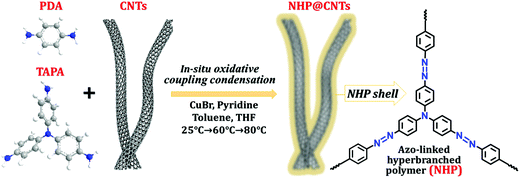 | ||
| Fig. 1 Chemical structures and synthesis route of NHP@CNTs by using a copper(I)-catalyzed oxidative coupling reaction. | ||
2. Experimental
2.1. Synthesis of NHP@CNTs
Azo-coupled polymers were synthesized by amino-containing monomers as reported in the literature.36,37 Typically, CuBr (40 mg, 0.279 mmol) and pyridine (160 mg, 2.023 mmol) were added to toluene (11 mL), and stirred for 3 h at room temperature. To the above solution was then added a mixture of tris(4-aminophenyl)amine (TAPA) (40 mg, 0.138 mmol), p-phenylenediamine (PDA) (23 mg, 0.206 mmol), and CNTs in tetrahydrofuran (11 mL) under stirring. The resulting suspension was further stirred under an air atmosphere at 25 °C for 24 h, 60 °C for 12 h, and 80 °C for 12 h, respectively. Afterward, the reaction mixture was separated by filtration and washing with water and tetrahydrofuran. The resulting brown solid was further stirred in HCl (100 mL, 2 M) for 12 h followed by washing with NaOH (100 mL, 2 M), water, ethanol, tetrahydrofuran, and chloroform. The final product was obtained by vacuum drying overnight at 120 °C. The loading amount of CNTs in NHP@CNTs was controlled by using the initial addition of 7, 16, and 27 mg, respectively. The resultant composites were accordingly designated as NHP@CNT-1, NHP@CNT-2, and NHP@CNT-3, respectively. As a control experiment, pure NHP was also synthesized under the same synthesis process in the absence of CNTs.2.2. Materials characterization
The US Thermo Nicolet NEXUS 470 Fourier Transform Infrared (FT-IR) Spectroscopy was used to characterize the chemical structures of new materials in the wavelength range of 450 to 4000 nm. Raman spectroscopy was performed on a Thermo Scientific DXR microscope Raman spectrometer with an excitation laser λ = 532 nm. X-ray photoelectron spectroscopy (XPS) was conducted on a Thermo Multi Lab 2000 spectrometer. Thermogravimetric analysis (TGA) was performed on a NETZSCH (TG209F3) analyzer under a nitrogen atmosphere with a heating rate of 10 °C min−1. The nitrogen adsorption/desorption isotherms were measured with a ASAP 2020 Plus surface analyzer (Micrometrics) after degassing the samples under vacuum at 120 °C for 15 h. A transmission electron microscope (TEM, Tecnai G220 S-TWIN, FEI, USA) and scanning electron microscope (SEM, SU8010, Hitachi, Japan) were used to determine material morphologies and microstructures.2.3. Electrochemical measurements
The cathode slurry was fabricated by grinding active materials (NHP or NHP@CNTs) with conductive carbon black (Super P) and polyvinylidene fluoride (PVDF) with a weight ratio of 6![[thin space (1/6-em)]](https://www.rsc.org/images/entities/char_2009.gif) :
:![[thin space (1/6-em)]](https://www.rsc.org/images/entities/char_2009.gif) 3
3![[thin space (1/6-em)]](https://www.rsc.org/images/entities/char_2009.gif) :
:![[thin space (1/6-em)]](https://www.rsc.org/images/entities/char_2009.gif) 1 in N-methyl-2-pyrrolidone (NMP). The resulting slurry was then cast uniformly onto aluminum foil followed by drying in a vacuum oven at 80 °C overnight. The mass loading of active materials is about 0.8 mg cm−2 on each circular electrode slice with a diameter of 10 mm. A CR2032-type half-cell using the lithium foil as the counter electrode was manufactured in a glove box filled with argon. The 1.0 M LiTFSI in 1,3-dioxolane (DOL) and dimethoxymethane (DME) (v/v = 2
1 in N-methyl-2-pyrrolidone (NMP). The resulting slurry was then cast uniformly onto aluminum foil followed by drying in a vacuum oven at 80 °C overnight. The mass loading of active materials is about 0.8 mg cm−2 on each circular electrode slice with a diameter of 10 mm. A CR2032-type half-cell using the lithium foil as the counter electrode was manufactured in a glove box filled with argon. The 1.0 M LiTFSI in 1,3-dioxolane (DOL) and dimethoxymethane (DME) (v/v = 2![[thin space (1/6-em)]](https://www.rsc.org/images/entities/char_2009.gif) :
:![[thin space (1/6-em)]](https://www.rsc.org/images/entities/char_2009.gif) 1) was used as the electrolyte. Galvanostatic charge/discharge (GCD) tests at various current densities were determined on a LAND CT2001A battery system (Wuhan, China) in the voltage range of 1 to 3.5 V. Cyclic voltammetry (CV) and electrochemical impedance spectroscopy (EIS) were performed on a CHI660 electrochemical workstation at room temperature.
1) was used as the electrolyte. Galvanostatic charge/discharge (GCD) tests at various current densities were determined on a LAND CT2001A battery system (Wuhan, China) in the voltage range of 1 to 3.5 V. Cyclic voltammetry (CV) and electrochemical impedance spectroscopy (EIS) were performed on a CHI660 electrochemical workstation at room temperature.
3. Results and discussion
3.1. Structural characteristics
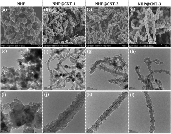
Azo compounds were readily synthesized by a copper(I)-catalyzed oxidative coupling condensation between aniline-like molecules.36,37Fig. 1 shows the route to prepare azo-coupled hyperbranched polymers (NHPs) in the absence of CNTs and the composites (NHP@CNTs) in the presence of CNTs. Two phenyl-enriched monomers of TAPA and PDA are favorable for uniform dispersing π-conjugated CNTs into the reaction solution.38 Accordingly, the subsequent in situ polymerization process allows for intimate contact between CNTs and the synchronously-generated NHP chains, forming core–shell nanostructures due to strong π–π noncovalent interactions between the two.39 The shell thickness of outer NHPs and loading amount of inside CNTs were also tailored by changing the feed ratio of CNTs to monomers.Both morphologies and microstructures of NHPs and NHP@CNTs were determined using both SEM and TEM techniques. As shown in Fig. 2(a, e and f), pure NHP exhibits a near-spherical morphology with an average diameter of 250 nm. In contrast to bare CNTs (Fig. S1, ESI†), all NHP@CNTs exhibit a very rough surface, and CNTs are fully encapsulated in the NHP shell to form core–shell nanostructures. The average thickness of the NHP shell around the surface of CNTs is about 67.7 nm for NHP@CNT-1 [Fig. 2(f and j)], 55.4 nm for NHP@CNT-2 [Fig. 2(g and k)], and 41.8 nm for NHP@CNT-3 [Fig. 2(h and l)], respectively. The thicker NHP shell and hence the larger diameter of NHP@CNTs [Fig. 2(b–d)] are attributable to the lower loading of CNTs and the higher amount of TAPA and PDA monomers during the in situ polymerization process. Apparently, the 1D surface-confined space of CNTs significantly reduces the size of NHP in NHP@CNTs, thus affording the high accessibility and electrochemical utilization of active sites.
Chemical structures of pure NHP and NHP@CNTs were further examined by spectroscopy techniques. NHP@CNT-2 was selected as an example to qualitatively verify its structural evolution. As shown in the FT-IR spectra, typical horseshoe-shaped double peaks for –NH2 (3100–3500 cm−1) in PDA and TAPA (Fig. 3a) are clearly observed that almost disappear after polymerization. A characteristic vibration peak of –N![[double bond, length as m-dash]](https://www.rsc.org/images/entities/char_e001.gif) N– at 1405 cm−1 appears in NHP and NHP@CNT-2, revealing the successful polymerization of monomers via an oxidative coupling reaction.28,29,40 Furthermore, the strong –N
N– at 1405 cm−1 appears in NHP and NHP@CNT-2, revealing the successful polymerization of monomers via an oxidative coupling reaction.28,29,40 Furthermore, the strong –N![[double bond, length as m-dash]](https://www.rsc.org/images/entities/char_e001.gif) N– peaks also occur at 1448 cm−1 in the Raman spectra of NHP and NHP@CNT-2 (Fig. 3b).28,41,42 Moreover, CNTs show two strong D (1340 cm−1) and G (1578 cm−1) bands corresponding to the disordered structure and sp2-hybridized configuration, respectively. The Raman spectrum of NHP@CNT-2 presents the higher intensities in both D and G bands compared to NHP due to the presence of CNTs.30
N– peaks also occur at 1448 cm−1 in the Raman spectra of NHP and NHP@CNT-2 (Fig. 3b).28,41,42 Moreover, CNTs show two strong D (1340 cm−1) and G (1578 cm−1) bands corresponding to the disordered structure and sp2-hybridized configuration, respectively. The Raman spectrum of NHP@CNT-2 presents the higher intensities in both D and G bands compared to NHP due to the presence of CNTs.30
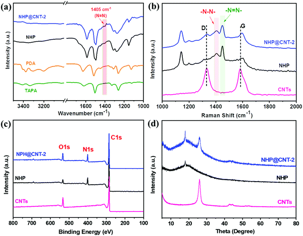 | ||
| Fig. 3 (a) FT-IR spectra, (b) Raman spectra, (c) XPS spectra, and (d) XRD patterns of NHP, NHP@CNTs, and CNTs. | ||
The chemical compositions of NHP and NHP@CNTs can be further verified by XPS. As shown in Fig. 3c, pure CNTs shows two main peaks of C 1s and O 1s. In comparison, NHP and NHP@CNT-2 exhibit additional N 1s peaks at around 400 eV due to the formation of azo bonds as a result of a copper(I)-catalyzed oxidative coupling condensation.26,29 The N 1s spectrum (Fig. S2, ESI†) was further resolved into two peaks centered at 400.2 eV, and 399.8 eV respectively, corresponding to the C–N and N![[double bond, length as m-dash]](https://www.rsc.org/images/entities/char_e001.gif) N groups in the NHP chains. In addition, the XRD pattern of NHP@CNT-2 (Fig. 3d) combines the characteristic diffraction peaks of pure NHP (2θ = 18°) and CNTs (2θ = 25.5°),43,44 in good accordance with the Raman and XPS results mentioned above.
N groups in the NHP chains. In addition, the XRD pattern of NHP@CNT-2 (Fig. 3d) combines the characteristic diffraction peaks of pure NHP (2θ = 18°) and CNTs (2θ = 25.5°),43,44 in good accordance with the Raman and XPS results mentioned above.
The loading amount of NHP in NHP@CNTs can be estimated by TGA in combination with the elemental analysis. As shown in Fig. 4a, CNTs show a mass loss above 500 °C due to thermal decomposition of oxygen-containing groups, and maintain a residual weight of 86.1% at 700 °C. NHP gives an initial weight loss of about 4.5% below 100 °C attributable to the removal of physically-adsorbed water, and then decomposes gradually after 200 °C and finally retains a weight of 64.1% at 700 °C due to the dissociation and carbonization of polymer chains. In contrast, NHP@CNT-1, NHP@CNT-2, and NHP@CNT-3 retain 71.4%, 75.2%, and 77.3% of their weight respectively, due to the high thermal stability enabled by CNTs. The accurate composition was further estimated by elemental analysis (Table S1, ESI†). The N content measured in pure NHP is 15.7% in weight, lower than the theoretical content of 17.7% calculated by the repeated structure units. However, the N signal is almost undetectable in bare CNTs. The actual N fractions are 13.0% in NHP@CNT-1, 11.5% in NHP@CNT-2, and 8.3% in NHP@CNT-3, respectively. Therefore, the loading amounts of CNTs are calculated to be about 17.4% in NHP@CNT-1, 26.8% in NHP@CNT-2, and 47.6% in NHP@CNT-3, respectively, by assuming that all N moieties come from the azo-coupled NHP moieties.
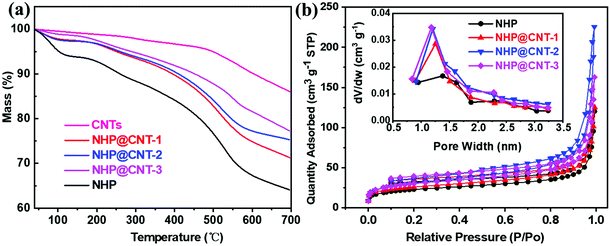 | ||
| Fig. 4 (a) TGA curves and (b) N2 adsorption/desorption isotherms (the insert showing pore diameter distribution diagrams) of NHP, NHP@CNTs, and CNTs. | ||
The N2 adsorption/desorption measurements were conducted to investigate the pore structures. As shown in Fig. 4b, all the isotherms of NHP and NHP@CNTs have an increased N2 uptake at a relatively high pressure, ascribed to the existence of a small amount of mesopores.28 Pore size distributions were estimated from the adsorption branch of isotherms by nonlocal density functional theory (NLDFT). The dominant peaks are centered at 1.25 nm associated with small peaks between 1.5–3 nm, indicating the predominance of micropores and the presence of a few mesopores in the hyperbranched topological structures of NHP moieties. Specific surface area was calculated based on the Brunauer–Emmett–Teller (BET) model. NHP@CNT-3 achieves a specific surface area of 110.2 m2 g−1, which is higher than those of NHP@CNT-2 (105.9 m2 g−1), NHP@CNT-1 (91.9 m2 g−1), and pure NHP (80.2 m2 g−1) due to the incorporation of more CNTs and the smaller diameter of the resulted NHP@CNTs. Accordingly, the pore volume is gradually increased from 0.19 cm3 g−1 for NHP to 0.21 cm3 g−1 for NHP@CNT-1, 0.25 cm3 g−1 for NHP@CNT-1, and 0.35 cm3 g−1 for NHP@CNT-3. In principle, the higher specific surface area and the greater pore volume would be more favorable for the electrolyte penetration and ion diffusion and hence, achieving high-rate lithium storage capability.30
3.2. Lithium-storage performance
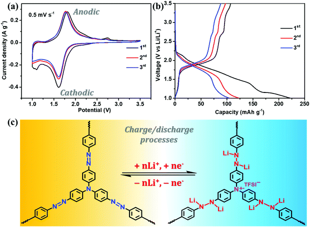
The electrochemical performance of NHP-based cathodes was studied using coin-type batteries in which the lithium foil served as the counter electrode. As shown in Fig. 5a, NHP@CNT-2 shows an irreversible shoulder peak at ca. 1.05 V in the first cathodic scan, possibly owing to the cathode activation and the formation of a solid electrolyte interface film.28 In the subsequent redox cycles, the nearly-overlapped CV profiles retain a strong and broad anodic peak centered at 1.78 V and a cathodic peak at 1.62 V, corresponding to the reversible oxidation/reduction reactions of azo units,28,29,45–48 as proposed in Fig. 5c. Another weak oxidation peak at ∼2.75 V is possibly ascribed to the cation radical state (Fig. 5c) of tertiary amine units in the NHP skeleton.49 It is generally difficult to distinguish the oxidizing nitrogen cation radicals during the charge process. However, tertiary amine sites derived from TAPA are covalently bridged by triphenyl groups and accordingly located in the center of the NHP backbone. Meanwhile, in such micropore-dominated hyperbranched topological structures, electrolyte salts are easily allowed for approaching the electroactive surfaces of NHP moieties.50 These accordingly enable the generation of nitrogen radical cations which could be subsequently stabilized by conjugated aromatic units, and electrostatically balanced by the neighboring anions (TFSI−) in the electrolyte.51,52 Such CV profiles can also be clearly identified in the NHP (Fig. S3a, ESI†), NHP@CNT-1 (Fig. S3b, ESI†), and NHP@CNT-3 (Fig. S3c, ESI†) cathodes. All the NHP@CNTs cathodes exhibit stronger redox peaks at the same rate compared to pure NHP in the same voltage window (Fig. S3d, ESI†), due to the conductive core and redox-active shell heterostructures capable of boosting redox kinetics and ion diffusion.53In their GCD profiles, NHP@CNT-2 (Fig. 5b) and their counterparts of NHP (Fig. S4a, ESI†), NHP@CNT-1 (Fig. S4b, ESI†), and NHP@CNT-3 (Fig. S4c, ESI†) cathodes show the primary discharge/charge plateau voltages in the range of 1.41 V to 2.05 V due to the reversible lithiation/delithiation processes of azo groups. A slight sloping charge platform above 2.6 V can be also observed (Fig. 5b) that agrees well with the CV results. The encapsulation of CNTs endows NHP@CNTs with higher stable capacities (over 80 mA h g−1) compared to NHP (below 70 mA h g−1, Fig. S4d, ESI†), due to the improved redox activity and electrochemical utilization rate of organic NHP shell layers.54
Rate and cycling performances of NHP-based cathode materials were further evaluated by GCD. As shown in Fig. 6a, all the NHP@CNTs cathodes deliver higher reversible capacities at each rate compared to pure NHP, suggesting their higher rate capabilities. The reversible capacity of the pure NHP cathode decreases significantly from 80 mA h g−1 to 10 mA h g−1 (much lower than its theoretical capacity of 243.6 mA h g−1, see the ESI†) when the current density increases from 0.05 A g−1 to 1.0 A g−1, with a capacity retention as low as 12.5%. By comparison, NHP@CNT-2 delivers high reversible capacities of 145, and 68 mA h g−1 at 0.05 A g−1 and 1.0 A g−1, respectively, and gives a higher capacity retention (46.9%) compared to pure NHP. Furthermore, after returning to 0.05 A g−1, NHP@CNT-2 still retains a capacity of 112 mA h g−1, which is also much larger than that of NHP (70 mA h g−1). Similarly, all the NHP@CNTs cathodes deliver higher reversible capacities after 160 cycles at the same rate of 0.05 A g−1 compared to pure NHP. As shown in Fig. 6b, the NHP cathode presents a relatively low initial charge capacity of 85 mA h g−1, and gradually decays to 25 mA h g−1 after 160 cycles. In contrast, NHP@CNT-1, NHP@CNT-2, and NHP@CNT-3 cathodes deliver specific capacities of 95, 145, and 120 mA h g−1 in the first cycle, and maintain reversible capacities of 70, 85, and 75 mA h g−1 after 160 cycles, respectively.
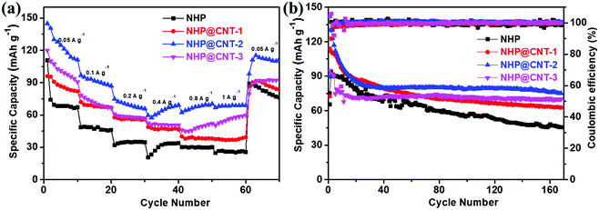 | ||
| Fig. 6 (a) Rate performance at different current densities, and (b) cycling stability measured at 0.05 A g−1 for NHP and NHP@CNTs cathodes. | ||
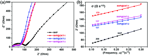
An EIS test was conducted to evaluate the electrochemical kinetics of NHP and NHP@CNTs electrodes. As shown in Fig. 7a, all the NHP@CNTs cathodes exhibit smaller diameters of semicircles in the high frequency range compared to pure NHP, suggesting their lower charge transfer resistances due to the enhanced electronic conductivity by CNTs. Typically, the NHP@CNT-2 cathode possesses the lowest charge transfer resistance (63.5 Ω). In the low frequency range, the slopes of approximately 45° inclined line are much greater than that of NHP, indicative of the lower ion diffusion resistance (σ) in NHP@CNTs.55 The fitted ion diffusion resistance values (Fig. 7b) for NHP@CNT-1, NHP@CNT-2, and NHP@CNT-3 cathodes are about 170, 127, and 137 Ω s−1/2, respectively, much lower than that of NHP (208 Ω s−1/2).
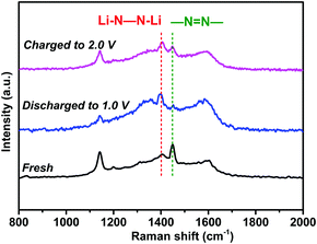
To verify the lithium storage mechanism, the chemical structure evolution was identified using ex situ spectroscopic techniques. As shown in Fig. 8, the characteristic Raman peak of azo groups (–N![[double bond, length as m-dash]](https://www.rsc.org/images/entities/char_e001.gif) N–) in the NHP moieties at 1448 cm−1 almost disappeared when the fresh electrode was fully discharged to 1.0 V. Instead, a new peak appears at 1395 cm−1, corresponding to the lithiated azo groups (Li–N–N–Li) due to the coordination of azo groups with Li ions during the discharge process.29,42 During the charging process from 1.0 V to 2.0 V, the characteristic peak of –N
N–) in the NHP moieties at 1448 cm−1 almost disappeared when the fresh electrode was fully discharged to 1.0 V. Instead, a new peak appears at 1395 cm−1, corresponding to the lithiated azo groups (Li–N–N–Li) due to the coordination of azo groups with Li ions during the discharge process.29,42 During the charging process from 1.0 V to 2.0 V, the characteristic peak of –N![[double bond, length as m-dash]](https://www.rsc.org/images/entities/char_e001.gif) N– recovers gradually, suggesting the reversible redox reactions between azo groups and Li ions.
N– recovers gradually, suggesting the reversible redox reactions between azo groups and Li ions.
As demonstrated above, the NHP@CNTs cathodes exhibit larger reversible capacities, better rate capability, and stronger cycling stability as well as lower charge transfer and ion diffusion resistances compared to its counterpart in the pure NHP cathode. Such excellent electrochemical performance can be rationally corroborated by the core–shell hetero-architectures of NHP@CNTs. Conductive CNTs are intimately encapsulated in the nano-sized redox-active NHP shell while significantly reducing the bulk dimension of pure NHP particles. Meanwhile, quasi 1D NHP@CNTs are interconnected to build 3D hierarchical networks, thus boosting the exposure of N-containing active sites in the hyperbranched configuration.56,57 Such synergetic characteristics are highly favorable for accelerating electron transport, facilitating electrolyte percolation and accessibility, reducing ion diffusion distances, and lowering the lithiation/delithiation barrier,58,59 and rationally account for significant improvements in lithium-storage performance for NHP@CNTs. Interestingly, NHP@CNT-2 shows the optimal performance among NHP@CNTs, possibly due to the appropriate loading of CNTs that inherit the inherent electron transport merits while preserving as much electrochemically-accessible sites of NHP shell as possible in the composites.58,60
4. Conclusions
Azo-coupled hyperbranched polymer-encapsulated CNTs were prepared by facile in situ polymerization to form core–shell nanostructures with tailored shell thickness. When used as cathodes for LIBs, the as-fabricated NHP@CNT electrodes deliver a high reversible capacity of 145 mA h g−1 at 0.05 A g−1, and retain 68.1 mA h g−1 at 1.0 A g−1, and 85 mA h g−1 after 160 cycles, respectively. The excellent electrochemical performance can be attributed to the synergistic merits of highly-conductive CNT cores and redox-active hyperbranched configurations of NHP shells. Remarkably, the robust contact between CNTs and NHP builds 3D networks, which ensure fast electron transport, abundant porous channels accessible to electrolytes, and efficient exposure of N-containing active sites for reversible lithiation/delithiation. This work would provide new insights into crafting inorganic/organic building blocks into sustainable metal-free electrodes for the next-generation of low cost and high-performance rechargeable batteries.Conflicts of interest
There are no conflicts to declare.Acknowledgements
This work was supported by the National Natural Science Foundation of China (52173091, and 51973235), the Program for Leading Talents of National Ethnic Affairs Commission of China (MZR21001), the Hubei Provincial Natural Science Foundation of China (2021CFA022), and the Wuhan Science and Technology Bureau (2020010601012198).References
- R. Van Noorden, Nature, 2014, 507, 26–28 CrossRef CAS PubMed.
- M. Li, J. Lu, Z. Chen and K. Amine, Adv. Mater., 2018, 30, 1800561 CrossRef PubMed.
- Y. Lu and J. Chen, Nat. Rev. Chem., 2020, 4, 127–142 CrossRef CAS.
- M. S. Whittingham, Chem. Rev., 2014, 114, 11414–11443 CrossRef CAS PubMed.
- K. Zhang, X. Han, Z. Hu, X. Zhang, Z. Tao and J. Chen, Chem. Soc. Rev., 2015, 44, 699–728 RSC.
- X. Cui, S. Lei, A. C. Wang, L. Gao, Q. Zhang, Y. Yang and Z. Lin, Nano Energy, 2020, 70, 104525 CrossRef CAS.
- X. Cui, L. Gao, R. Ma, Z. Wei, C.-H. Lu, Z. Li and Y. Yang, J. Mater. Chem. A, 2021, 9, 20985–21004 RSC.
- G. Lin, Y. Jiang, C. He, Z. Huang, X. Zhang and Y. Yang, Dalton Trans., 2019, 48, 5773–5778 RSC.
- C. He, Z. Liu, H. Peng, Y. Yang, D. Shi and X. Xie, Electrochim. Acta, 2016, 222, 1393–1401 CrossRef CAS.
- R. Li, C. He, L. Cheng, G. Lin, G. Wang, D. Shi, R. K.-Y. Li and Y. Yang, Composites, Part B, 2017, 121, 75–82 CrossRef CAS.
- C. He, S. Qiu, S. Sun, Q. Zhang, G. Lin, S. Lei, X. Han and Y. Yang, Energy Environ. Mater., 2018, 1, 88–95 CrossRef CAS.
- Y. Lu, C. He, P. Gao, S. Qiu, X. Han, D. Shi, A. Zhang and Y. Yang, J. Mater. Chem. A, 2017, 5, 23513–23522 RSC.
- D. Larcher and J. M. Tarascon, Nat. Chem., 2015, 7, 19–29 CrossRef CAS PubMed.
- J. Xie and Q. Zhang, Mater. Today Energy, 2020, 18, 100547 CrossRef CAS.
- Q. Zhang, X. Cui, S. Hao, Q. Zhang, Z. Guo, H. Li, Z. Lin and Y. Yang, Mater. Today, 2021, 50, 170–198 CrossRef CAS.
- Q. Zhang, Q. Huang, S.-M. Hao, S. Deng, Q. He, Z. Lin and Y. Yang, Adv. Sci., 2022, 9, 2103798 CrossRef CAS PubMed.
- N. Oyama, T. Tatsuma, T. Sato and T. Sotomura, Nature, 1995, 373, 598–600 CrossRef CAS.
- S.-R. Deng, L.-B. Kong, G.-Q. Hu, T. Wu, D. Li, Y.-H. Zhou and Z.-Y. Li, Electrochim. Acta, 2006, 51, 2589–2593 CrossRef CAS.
- T. Janoschka, M. D. Hager and U. S. Schubert, Adv. Mater., 2012, 24, 6397–6409 CrossRef CAS PubMed.
- T. Jähnert, M. D. Hager and U. S. Schubert, J. Mater. Chem. A, 2014, 2, 15234–15251 RSC.
- M. Park, D.-S. Shin, J. Ryu, M. Choi, N. Park, S. Y. Hong and J. Cho, Adv. Mater., 2015, 27, 5141–5146 CrossRef CAS PubMed.
- S. Wang, L. Wang, K. Zhang, Z. Zhu, Z. Tao and J. Chen, Nano Lett., 2013, 13, 4404–4409 CrossRef CAS PubMed.
- C. Luo, R. Huang, R. Kevorkyants, M. Pavanello, H. He and C. Wang, Nano Lett., 2014, 14, 1596–1602 CrossRef CAS PubMed.
- X. Han, C. Chang, L. Yuan, T. Sun and J. Sun, Adv. Mater., 2007, 19, 1616–1621 CrossRef CAS.
- M. Wu, Y. Zhao, B. Sun, Z. Sun, C. Li, Y. Han, L. Xu, Z. Ge, Y. Ren, M. Zhang, Q. Zhang, Y. Lu, W. Wang, Y. Ma and Y. Chen, Nano Energy, 2020, 70, 104498 CrossRef CAS.
- M. Lee, J. Hong, D.-H. Seo, D. H. Nam, K. T. Nam, K. Kang and C. B. Park, Angew. Chem., Int. Ed., 2013, 52, 8171 CrossRef CAS.
- H. Wu, J. Zhang, X. Du, M. Zhang, J. Yang, J. Zhang, T. Luo, H. Liu, H. Xu and G. Cui, Chem. Commun., 2019, 55, 11370–11373 RSC.
- C. Wu, M. Hu, X. Yan, G. Shan, J. Liu and J. Yang, Energy Storage Mater., 2021, 36, 347–354 CrossRef.
- K. S. Weeraratne, A. A. Alzharani and H. M. El-Kaderi, ACS Appl. Mater. Interfaces, 2019, 11, 23520–23526 CrossRef CAS PubMed.
- Q. Liu, Z. Xiao, X. Cui, S. Deng, Q. He, Q. Zhang, Z. Lin and Y. Yang, J. Mater. Chem. A, 2021, 9, 6962–6970 RSC.
- C.-J. Yao, Z. Wu, J. Xie, F. Yu, W. Guo, Z. J. Xu, D.-S. Li, S. Zhang and Q. Zhang, ChemSusChem, 2020, 13, 2457–2463 CrossRef CAS PubMed.
- T. Sun, J. Xie, W. Guo, D.-S. Li and Q. Zhang, Adv. Energy Mater., 2020, 10, 1904199 CrossRef CAS.
- Q. Zhang, G. Lin, Y. He, X. Cui and Y. Yang, Mater. Today Chem., 2020, 17, 100341 CrossRef CAS.
- X. Liu, S. Qiu, P. Mei, Q. Zhang and Y. Yang, J. Mater. Sci., 2021, 56, 3900–3910 CrossRef CAS.
- Z. Sha, S. Qiu, Q. Zhang, Z. Huang, X. Cui, Y. Yang and Z. Lin, J. Mater. Chem. A, 2019, 7, 23019–23027 RSC.
- P. Arab, E. Parrish, T. İslamoğlu and H. M. El-Kaderi, J. Mater. Chem. A, 2015, 3, 20586–20594 RSC.
- P. Arab, M. G. Rabbani, A. K. Sekizkardes, T. İslamoğlu and H. M. El-Kaderi, Chem. Mater., 2014, 26, 1385–1392 CrossRef CAS.
- Y. Dou, J. Zhang, X. Han, Q. He and Y. Yang, Nanotechnol. Rev., 2022, 11, 824–833 CrossRef CAS.
- Y. Dou, H. Li, Y. Dong, X. Zhang, K. Chen and Y. Yang, ACS Appl. Energy Mater., 2022, 5, 1331–1340 CrossRef CAS.
- Q. Li, H. Wang, H.-G. Wang, Z. Si, C. Li and J. Bai, ChemSusChem, 2020, 13, 2449–2456 CrossRef CAS PubMed.
- C. Luo, X. Ji, S. Hou, N. Eidson, X. Fan, Y. Liang, T. Deng, J. Jiang and C. Wang, Adv. Mater., 2018, 30, 1706498 CrossRef PubMed.
- G. Zhao, Y. Zhang, Z. Gao, H. Li, S. Liu, S. Cai, X. Yang, H. Guo and X. Sun, ACS Energy Lett., 2020, 5, 1022–1031 CrossRef CAS.
- T. A. Saleh, M. A. Gondal, Q. A. Drmosh, Z. H. Yamani and A. Al-yamani, Chem. Eng. J., 2011, 166, 407–412 CrossRef CAS.
- C. Lu, F. Su and S. Hu, Appl. Surf. Sci., 2008, 254, 7035–7041 CrossRef CAS.
- C. Luo, O. Borodin, X. Ji, S. Hou, K. J. Gaskell, X. Fan, J. Chen, T. Deng, R. Wang, J. Jiang and C. Wang, Proc. Natl. Acad. Sci. U. S. A., 2018, 115, 2004–2009 CrossRef CAS PubMed.
- Y. Liang, C. Luo, F. Wang, S. Hou, S.-C. Liou, T. Qing, Q. Li, J. Zheng, C. Cui and C. Wang, Adv. Energy Mater., 2019, 9, 1802986 CrossRef.
- C. Luo, G.-L. Xu, X. Ji, S. Hou, L. Chen, F. Wang, J. Jiang, Z. Chen, Y. Ren, K. Amine and C. Wang, Angew. Chem., Int. Ed., 2018, 57, 2879–2883 CrossRef CAS PubMed.
- C. Luo, X. Ji, J. Chen, K. J. Gaskell, X. He, Y. Liang, J. Jiang and C. Wang, Angew. Chem., Int. Ed., 2018, 57, 8567–8571 CrossRef CAS PubMed.
- C. Zhang, X. Yang, W. Ren, Y. Wang, F. Su and J.-X. Jiang, J. Power Sources, 2016, 317, 49–56 CrossRef CAS.
- J. K. Feng, Y. L. Cao, X. P. Ai and H. X. Yang, J. Power Sources, 2008, 177, 199–204 CrossRef CAS.
- M. Wu, Y. Zhao, R. Zhao, J. Zhu, J. Liu, Y. Zhang, C. Li, Y. Ma, H. Zhang and Y. Chen, Adv. Funct. Mater., 2022, 32, 2107703 CrossRef CAS.
- W. Huang, T. Jia, G. Zhou, S. Chen, Q. Hou, Y. Wang, S. Luo, G. Shi and B. Xu, Electrochim. Acta, 2018, 283, 1284–1290 CrossRef CAS.
- J. Li, F. Huo, T. Chen, H. Yan, Y. Yang, S. Zhang and S. Chen, Energy Storage Mater., 2021, 40, 394–401 CrossRef.
- N. Patil, A. Aqil, F. Ouhib, S. Admassie, O. Inganäs, C. Jérôme and C. Detrembleur, Adv. Mater., 2017, 29, 1703373 CrossRef PubMed.
- F. Jiang, S. Li, P. Ge, H. Tang, S. A. Khoso, C. Zhang, Y. Yang, H. Hou, Y. Hu, W. Sun and X. Ji, Front. Chem., 2018, 6, 389 CrossRef PubMed.
- M. Lee, J. Hong, H. Kim, H.-D. Lim, S. B. Cho, K. Kang and C. B. Park, Adv. Mater., 2014, 26, 2558–2565 CrossRef CAS PubMed.
- D. Tang, W. Zhang, Z.-A. Qiao, Y. Liu and D. Wang, Mater. Lett., 2018, 214, 107–110 CrossRef CAS.
- Z. Lei, Q. Yang, Y. Xu, S. Guo, W. Sun, H. Liu, L.-P. Lv, Y. Zhang and Y. Wang, Nat. Commun., 2018, 9, 576 CrossRef PubMed.
- S. Kong, J. Xu, G. Lin, S. Zhang, W. Dong, J. Wang and F. Huang, Chem. Commun., 2020, 56, 10289–10292 RSC.
- Z. Zhang, Y. Zhou, P. Chen, S. Zeng, W. Nie and Y. Xu, ACS Appl. Energy Mater., 2021, 4, 12882–12891 CrossRef CAS.
Footnote |
| † Electronic supplementary information (ESI) available. See DOI: https://doi.org/10.1039/d2ma00330a |
| This journal is © The Royal Society of Chemistry 2022 |

