
 Open Access Article
 This Open Access Article is licensed under a
 Creative Commons Attribution 3.0 Unported Licence
Recent progress and prospects of random lasers using advanced materials
Nideesh
Padiyakkuth
a,
Sabu
Thomas
 b,
Rodolphe
Antoine
*c and
Nandakumar
Kalarikkal
*a
b,
Rodolphe
Antoine
*c and
Nandakumar
Kalarikkal
*a
aSchool of Pure and Applied Physics, Mahatma Gandhi University, Priyadarsini Hills P O, Kottayam-686560, India. E-mail: nkalarikkal@mgu.ac.in
bSchool of Energy Materials, Mahatma Gandhi University, Priyadarsini Hills P O, Kottayam-686560, India
cInstitut Lumière Matière UMR 5306, Univ Lyon, Université Claude Bernard Lyon 1, CNRS, F-69100 Villeurbanne, France. E-mail: rodolphe.antoine@univ-lyon1.fr
First published on 6th July 2022
Abstract
Random lasers (RLs) are a particular class of optical devices. In a random laser, the optical feedback is provided by scattering media rather than by an optical cavity, as for traditional lasers. Such unique configuration leads to lasers with low spatial coherence and renders RLs attractive in the fields such as speckle-free imaging, sensing, and light therapy. The random laser generation depends on the gain and disordered scattering medium to obtain feedback and optical amplification. Therefore, the properties of the gain and scattering materials had particular importance for random lasers. The advancement of disordered nanostructure-based optical devices for photonic applications may further facilitate distinct and novel functionalities in RLs. However, the applicability of RLs has been restricted due to emission in random directions, polarization and wavelength tunability difficulties, and intense competition of modes. This review will discuss the recent progress and prospects of random lasers using advanced materials to address these limitations for RLs. Finally, some applications of RLs, including medical and diagnostics, photonic devices, sensors, and display technology, will be briefly reviewed.
 Nideesh Padiyakkuth | Mr Nideesh PK is a DST inspire Senior research fellow (a prestigious award from Department of Science and Technology, Govt. of India) at the School of Pure and Applied Physics, Mahatma Gandhi University. He is a student member of the international society for optics and photonics (SPIE) and the Optical Society of America (OSA). He qualified National level GATE examination in 2019. He has been a DST inspire scholar from 2013 onwards. He completed his Masters in Physics from Govt. College, Kottayam, affiliated with Mahatma Gandhi University. His research interest involves mesoscopic optics, non-linear optics, nanophotonics and random lasers. |
 Sabu Thomas | Professor Sabu Thomas is currently the Vice-Chancellor of Mahatma Gandhi University and the Founder Director of the International and Interuniversity Centre for Nanoscience and Nanotechnology. Prof. Thomas research interests comprises of Nanoscience, Polymer Science and Engineering. In collaboration with India's premier tyre company, Apollo Tyres, Professor Thomas's group invented new high performance barrier rubber nanocomposite membranes for inner tubes and inner liners for tyres. Prof. Thomas has published over 1500+ peer-reviewed research papers, including reviews and book chapters. He is the inventor of 5 patents. The H index of Prof. Thomas is 122 and has more than 70000+ citations. |
 Rodolphe Antoine | Rodolphe Antoine received his PhD in Molecular Physics from The University of Lyon. He was a postdoctoral researcher at the Swiss Federal Institute of Technology Lausanne, in non-linear optics at interfaces. His background spans atomic and molecular physics, laser spectroscopy, and physical chemistry. He has broad, multi-disciplinary interests in both experimental and computational avenues of research related to nanoclusters. He is currently a research group leader at the Institut Lumière Matière. The co-authors have been collaborating since 5 years in the field of light conversion (in particular non-linear optical materials and random lasers) through the bi-lateral International Emerging Actions funded by CNRS. |
 Nandakumar Kalarikkal | Prof. Nandakumar Kalarikkal is currently a Senior Professor at the School of Pure and Applied Physics, Mahatma Gandhi University, Kottayam, Kerala, India. His areas of interest are nanostructured materials and applications. He is the receipt of several national and international research grants. He was Professor@Lorraine, France, CNRS Professor@ILM Lyon, Claude Bernard University Lyon 1, France and Visiting Professor at various international institutions in Europe. He has 6 patents and 30+ books to his credit. In addition, he has about 400+ publications and over 6000+ citations, with an h-index of 43. He received his MSc degree in Industrial Physics and PhD in semiconductor physics from Cochin University of Science and Technology, Kerala, India. |
1. Introduction
Laser technology is one of the most inventive innovations1 and was a milestone for scientific research. The key to such kinds of optical devices is light amplification. A conventional laser requires two significant constituents (Fig. 1a): (i) an active material for light amplification and (ii) a feedback mechanism for confining the light to make the amplification much more effective. However, think of a laser without a conventional feedback mechanism that uses mirrors. Here the concept of “mirrorless lasing” emerges,2,3 which Letokhov initially proposed. Generally, scattering causes cavity loss and is treated as a harmful ingredient that should be circumvented. However, the latest findings established astonishing benefits of strong scattering in generating lasing-like phenomena.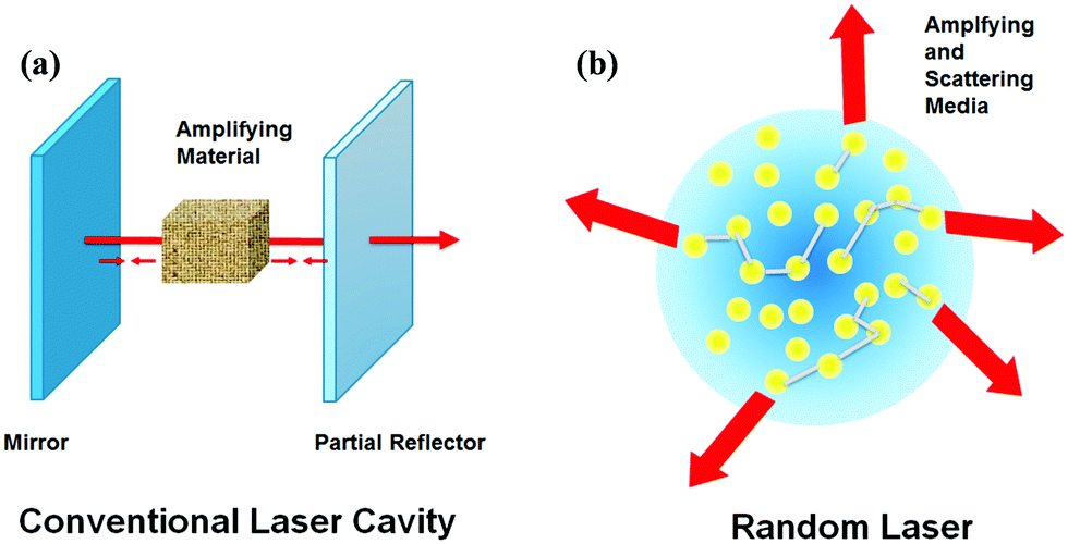 | ||
| Fig. 1 Schematic of Conventional laser (a) having two mirrors (the optical cavity) and an active medium. (b) Random laser having multiple scattering between disordered particles confining the light in the medium. | ||
Imagine a gain medium with numerous scattering centers. When the light passes through such a medium, photons encounter multiple scattering before they get off from the system, thereby increasing the dwell time of photons in the medium. It, in turn, raises the amplification efficiency of light. So instead of using additional reflectors in the medium, scattering will entrap the light. The term “Random media” defines this kind of a disordered medium. The basic principle behind random lasing is shown in Fig. 1. The term random lasing was initially published and introduced in 1994.4,5 The random laser (RL) generation depends only on the gain medium and the disordered scattering medium to obtain feedback and optical amplification.
Depending on the feedback mechanism, random lasers can be classified into two types: (1) incoherent energy feedback6 and (2) coherent field or amplitude feedback.7,8 Over the last several years, different random nanostructured materials9 have been developed and designed to offer gain, scattering, and sometimes both for RLs. Such unique configuration leads to lasers with low spatial coherence. Therefore, it renders RLs as an attractive platform for many applications such as cancer diagnostic,10,11 Photonic barcodes,12 a random spectrometer on a chip,13 speckle-free bio-imaging,14 speckle-free pulsed imaging technique,15 sensing,16,17 optical batteries18 and optomicrofluidics.19–21
The first type of RLs were dye-based colloidal systems4,22 and then on many other systems like photonic crystals,23,24 semiconductors,25–27 quantum dots (QDs),28,29 polymeric matrices,30,31 biological tissues,32 rare-earth-doped nanopowders,33 cold atoms,34etc. were introduced in the field. Several other phenomena, such as surface plasmon resonance, upconversion, and Raman scattering, have been exploited to enrich the random lasing capabilities. However, controlling directions tunability in polarization and wavelength are challenging issues.
In this review paper, we will provide an updated vision of advanced materials developed for RLs after a basic theoretical framework. In particular, we will discuss the recent progress and prospects of advanced materials developed to address current limitations for RLs (as summarized in Fig. 2). Furthermore, we also highlight technological applications that include sensing, optical amplification, and biomedical imaging. The review concludes by pointing out new directions in materials development in the field of RLs. This review aims to update the literature (since a comprehensive review on the subject was published in 20159 to which the readers are referred) and recent advances in materials for elaborating RLs beyond 2015.
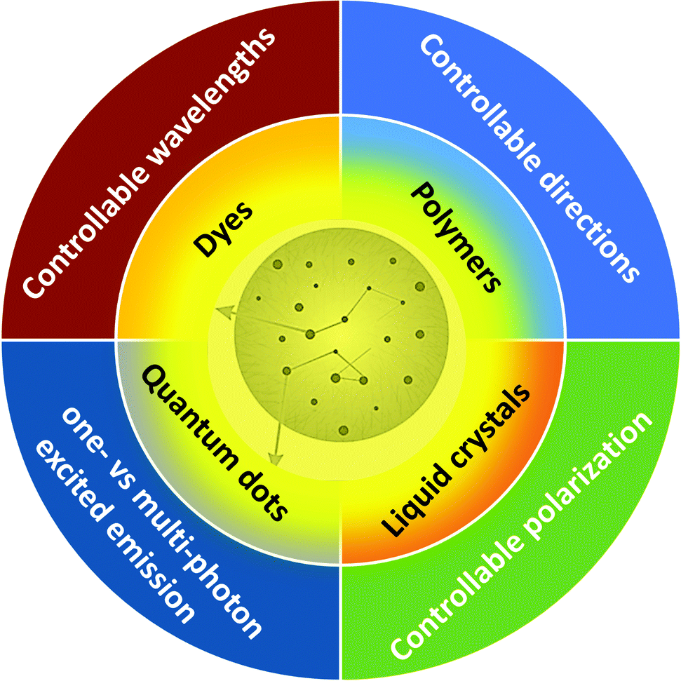 | ||
| Fig. 2 Schematic diagram of advanced materials and strategies used to tailor random lasing devices. | ||
2. Basic terminologies and concepts
In addition to random lasing systems detailed in this review, there are other optically pumped mirrorless lasing systems such as photonic structures, surface nanoplasmonic structures, and microcavities.24For example, a selective Bragg reflection phenomenon is used in photonic crystals. Likewise, in metal nanoparticles (NPs), surface plasmons, and in microcavities, total internal reflection is used as the working principle mechanism. Mode structures are critical aspects of lasers, and in conventional lasers, modes are determined by the cavity. Confinement of light in a random laser solely depends on multiple random scattering rather than resonant optical cavities, and it utilizes highly disordered materials to achieve laser-like action. The working principle of a random laser is similar to that of a conventional laser, there is a threshold value, and the laser will be emitted when the total gain of the system is greater than the loss. However, the mode of the random laser is also very different from that of a conventional laser in that it is determined by multiple scattering rather than by the laser cavity. Random lasers can be produced in both weakly scattering and strongly scattering systems.
Nevertheless, there is no need for precision arrangement and alignment of optical components in RLs. Instead, the interference effects are crucial in describing the structure of modes. The term speckle implies a granular intensity distribution due to interference in multiple scattering. Laser speckle is the signature symbol of interference in randomly scattered light waves. When light encounters a random medium, the multi-scattered light wave and the newly generated light will interfere. But according to lethokov's theory, he did not consider these effects. Instead, he took a diffusive model with gain (Random walk).
In some disordered materials, interference causes light localization, an optical analogue of Anderson localization of electrons. The phenomenon of light/photon localization can be explained in terms of randomly formed closed modes. The amplitude of this mode will decay exponentially. Localization length is the average spatial range of these confined modes, and this kind of localization occurs particularly in optical materials with high disorder or randomness. It, in turn, led to strong scattering processes. For a quantitative description, it is essential to get acquainted with another length scale called mean free path. It is the average step size in a random walk. Two different mean free paths have to be considered to describe the transport of light in disordered media (i) Scattering mean free path and (ii) transport mean free path (Fig. 3c). Scattering mean free path is the length between two consecutive scattering events, at which the photon flux intensity decreases by a factor of 1/e and is denoted by LS. We can show this as LS = 1/ρσS, where ρ is the density of the particles and σS is the scattering cross-section. The average distance beyond which the scattered light is randomized is termed as transport mean free path and is expressed as LT (as shown in Fig. 3c). It can be written as LT = 1/ρσt, where σt is the transport scattering cross-section. Theoretically, scattering events are of two sorts: (i) Isotropic and (ii) anisotropic scattering. For these two cases, a mathematical relationship can be established between scattering and transport mean free paths, i.e., LS ∼LT for isotropic scattering and LT = LS/1 − 〈cos![[thin space (1/6-em)]](https://www.rsc.org/images/entities/char_2009.gif) θ〉 for anisotropic case, where 〈cosθ〉 is the average cosine of the scattering angle.
θ〉 for anisotropic case, where 〈cosθ〉 is the average cosine of the scattering angle.
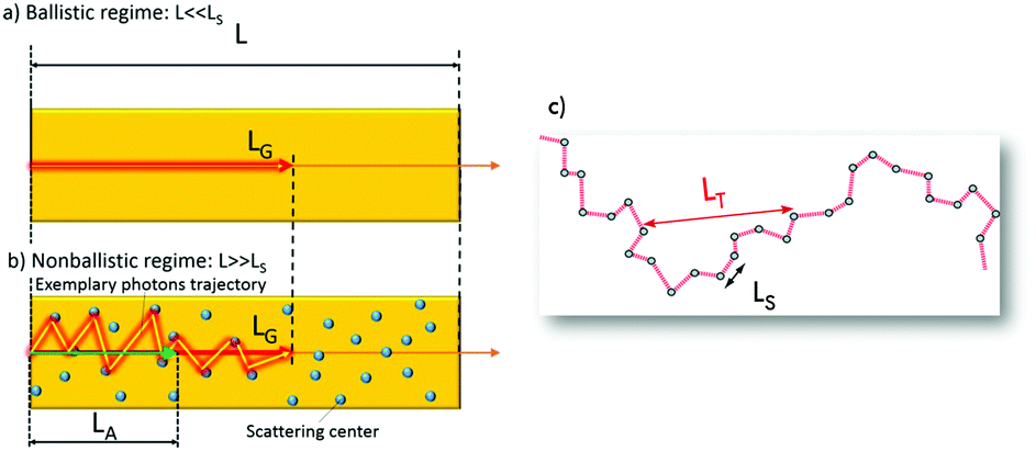 | ||
| Fig. 3 Schematic of (a) ballistic and (b) non-ballistic regime (L is the size of the random medium (for example its length in 1D), LG and LA are the gain and amplification lengths receptively). (c) Representation of length scales (LT and LS are transport and scattering mean free paths respectively). ((a) and (b) is reproduced from ref. 31, with permission from [John Wiley and Sons]). | ||
Amplification of light via stimulated emission process can be characterised by defining two other length scales35 (Fig. 3a and b). (a) The gain length (LG) and (b) the amplification length (LA). These quantities are employed to specify how the stimulated emission led to the amplification of light (Fig. 3). When light passes through a gain medium with scatterers, the light is amplified by ‘e’ following a certain distance, identified as the LG. The LA is defined by taking root mean square of the distance connecting the beginning and final points of LG. If there is no scatterer in the medium, the light will not experience scattering events and follow a straight or horizontal-line trajectory. Then the LG is equal to the LA Absorption length is yet another length scale. To describe this parameter, defining a quantity analogue to LG called inelastic length LI is needed. The length of the path travelled by a photon above which intensity is decreased to 1/e because of absorption. Similarly, a quantity that is analogue to LA exists as well, and this length parameter is called absorption length, calculated as 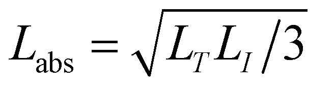 . For localizing photons, the mean free path must be smaller than the reciprocal wave vector, i.e., kLS ≤ 1, and this condition is called Ioffe–Regel criterion.36
For a 3D disordered medium, three major regimes are of great interest, and this can be characterized by the system properties such as, LT, the wavelength of light, λ and system size, L.
(1) The ballistic regime LT ≥ L
(2) Diffusive regime λ < LT < L
(3) Localization regime LS ≤ λ
If the light is forced to change the propagation direction by putting scatterers in the random media, scattering occurs in the system. Scattering can be of two types, elastic and inelastic scattering. Depending on the size of the scatterer, elastic scattering can be explained via different models. For example, if the particle size is much lower than the light wavelength, it refers to Rayleigh scattering. LT is equal to the scattering mean free path for this scattering. On the other hand, if the scatterer's size (consider the shape as a sphere) is close to the light wavelength, the model that accurately explains the scattering properties is Mie scattering.
Several time scales are also involved in the phenomenon of random lasing. A photon in the diffusive regime with diffusion constant, D, spends some time in the medium. It is called photon transport time τD and can be expressed mathematically as τD = L2/D whereas the decay time of spontaneous emission generally falls under the nanosecond time regime. The decay time related to stimulated emission is much smaller (about 1–10 ps time scales). Lasing is also characterized by the period over which fast relaxation oscillations occur.
Depending on the feedback mechanism, random lasers can be classified into two types: (1) incoherent energy feedback and (2) coherent field or amplitude feedback. Incoherent random lasers are based on energy density or energy feedback and are often produced in weak scattering regimes. For such a scattering regime, the light is scattered several times and the direction of light propagation changes at each scattering. Here the light in the scattering medium cannot return to its original position or, in terms of mode theory, the scattered light causes a large number of resonances of low Q values that overlap in the spectrum to form a continuous spectrum (i.e., a random laser with nonresonant feedback). On the other hand, Cao et al. first observed a coherent RL in semiconductor powder.37 Various anisotropic random laser emission spectra were observed after pumping ZnO powders and polycrystalline films with a pulsed laser and pumping light intensity above a threshold value. This demonstrated the existence of coherent resonance feedback, i.e., interference, and showed that the consideration of the optical field phase is important. Due to the small scattering mean free-range Ls, the emitted light scatters so strongly that a closed toroidal cavity is formed in different regions, which in turn forms an interference. And different peaks of laser emission are observed when pumped in different regions or received in different regions. However, the theory and examples of coherent field-based random lasers have not been fully demonstrated.
3. General considerations and examples for active platforms of RL
Generally, gain media plays a crucial role in the context of lasers. Achievement of gain in lasers is complicated as well as a difficult task. Regarding mirrorless lasing, gain media mainly falls into the following categories: random optical media, photonic media, and microcavities.38 Laser dyes and QDs are the most popularly used gain materials. In RLs, some experiments utilise semiconductors (ZnO,39–41 ZnS,42–44 GaAs45,46etc.) and with some doped semiconductors (Cr2+: ZnSe and Cr2+: ZnS,47etc.) as the gain media because of their reasonably large bandgap. Interestingly these materials have also been utilized as the active media, which provide both gain and scattering. Usually, sub-micrometre size nanoparticles are efficient light scatterers. A large refractive index and transparency from the visible to near-infrared are key properties for efficient scattering particles. Such criteria are completely fulfilled with TiO2 NPs, the most utilised ingredient for colloidal RLs. Unfortunately the TiO2 NPs solutions present poor stability due to the fast precipitation of the NPs, and their deposition on the cuvette walls that degrade the RL emission. Therefore several other scatterers include particles composed of zinc oxide, silica, TiO2–silica core–shell, alumina, tungsten oxide and nanoclays, ferromagnetic particles, polymeric fiber networks an even liquid crystals in ordered phases have been used to efficiently scatter light in colloidal RLs.Laser dyes, the most commonly used gain media, are incorporated with nanomaterials scatterers such as ZnO, TiO2, WO3, biological tissues,48 nematic liquid crystals49–55etc. When the dyes are injected into biologically active tissues, RL is generated in the system, which can be applied to separate cancerous and normal tissues.48,56 Hongbo Lu et al. introduced a dye-doped polymer-stabilised cholesteric liquid crystal used as the RL system.57 The output emission is obtained at the band edge of the photonic bandgap, and the wavelength of this RL can be tuned accordingly with the electric field.
As already mentioned, the refractive index plays a substantial role while considering photon scattering. The refractive index must be greater than that of the gain medium. Pores in the system structure can also scatter the light due to index mismatch. In 2021, Yukari Sakurayama et al. used porous zirconia media with rhodamine B as the gain medium.58 Here the pores act as the scatterer. Likewise, Xiang Meng et al. demonstrated a tunable RL with dye-doped poly ethylene glycol diacrylate (PEG–DA) hydrogel.59 The system is highly flexible and characterized by low threshold energy. The porous structure inside the hydrogel served as light scattering center. The wavelength of this RL system can be tuned by varying the temperature, and also, they have explored the possibility of phototherapy, as depicted in Fig. 4. This opens up new exciting areas of further research. Designing the RL platforms is an important aspect that will give optimum conditions for the scatterers for excellent scattering. A recent article discussed the random lasing behaviour of several metals and dielectric particles with different shapes (triangle and sphere) via the calculation of scattering cross-section.60 ZnO nanorod arrays (NA) can be utilized as one of the good scatterers in random lasing. Instead, Abdullah Taha Ali et al. employed SiO2 with different thicknesses, capped by the ZnO NA.61 As a result spontaneous emission peak is entirely suppressed by 100 nm SiO2, where the random lasing peaks completely dominate.
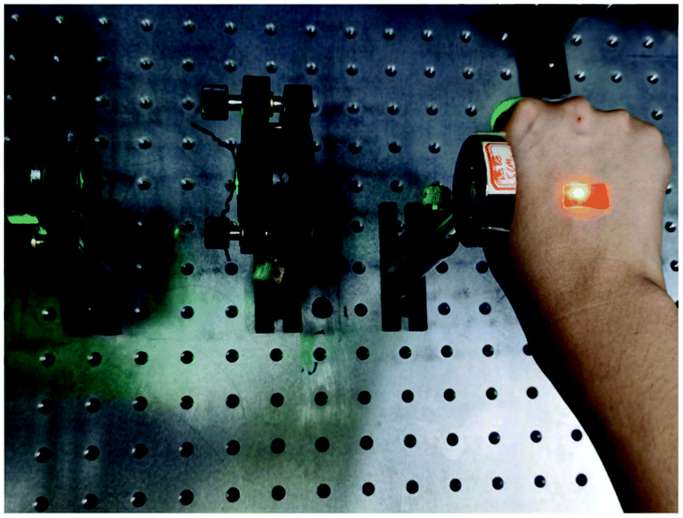 | ||
| Fig. 4 Laser pumping experiment of hydrogel attached to the hand (Reproduced from ref. 59, with permission from [Elsevier]). | ||
Because of higher biocompatibility and less toxicity, metal nanoclusters (MNCs)62 are now turning out to be an emerging field of research, and they can serve as a platform for RLs. Integrating highly luminescent MNCs with hyperbolic metamaterials (HMM) gives strong random lasing action with low threshold energy, as shown in Fig. 5. Silver metal nanoclusters (Ag–TSA MNC) films act as the gain medium, and HMM forms the possibility of trapping the light for the necessary RL action.63
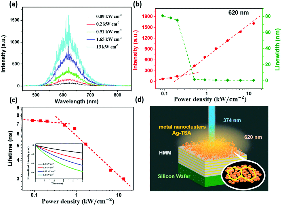 | ||
| Fig. 5 (a) Emission spectra of the solid-state assembly of Ag–TSA MNCs over HMM under different pumping power densities of 374 nm pulsed pump excitation. (b) Emission intensity and line width as a function of the pumping power density showcasing the low threshold value (0.5 kW cm−2) of pump power density for the solid-state assembly of Ag–TSA MNCs over HMM. (c) Carrier lifetime as a function of the pumping power density for the solid-state assembly of Ag–TSA MNCs over HMM (inset: time-resolved photoluminescence (TRPL) measurements for the solid-state assembly of Ag–TSA MNCs over HMM under different pumping power densities of 374 nm pulsed pump excitation). (d) Schematic illustration of the stimulated emissions from the solid-state assembly of Ag–TSA MNCs over HMM under 374 nm pulsed pump excitation (Reproduced from ref. 63, with permission from [American Chemical Society]). | ||
Another interesting work is done by E. Mendicuti et al. in which RL output emission is achieved from whole blood as the gain medium and SiO2 suspended in an isotonic solvent as the scatterer.64 This introduces numerous prospects for further complex biological systems research in the field of RLs. Rare-earth doped glasses or crystals are yet another gain medium, e.g., Neodymium doped powders.65 QDs are an interesting active medium with the property of size-dependent emission wavelengths over a broad spectral range. It can offer scattering since it has a reasonably higher refractive index than the surrounding medium. Another effective medium is based on polymer matrices.6,42,66,67 They can serve as a scatterer, gain, or sometimes both. Polymer matrices are inert in several cases, so some active scatterers like ZnO provide scattering and gain, and in this case, the polymer acts as a host material for ZnO.
Some recent results using different materials for scatterers and gain media are listed in Table 1.
| Gain medium | Scatterer | Remarks | Threshold | Ref. |
|---|---|---|---|---|
| GaAs | AlGaAs shell | Resonant and Nonresonant Lasing Modes | 617 μJ cm−2 for ASE and emergence of lasing above 1194 μJ cm−2 | 45 |
| Rhodamin B dye in ethylene glycol | Graphene quantum dots (GQDs) | Resonant RL emission | — | 68 |
| Rhodamine 6g | Kaolinite nanoclay | Introduced a new non toxic scatterer material for RL | 40 μJ per pulse | 69 |
| Ba (NO3)2 | Ba (NO3)2 | Resonant Raman random lasing | 18 MW cm−2 | 70 |
| Rhodamine 6G in the chitosan–glycerin mixture | Silver nanoflowers | A humidity-tailored film RL | 0.095 MWcm−2 and 0.750 MW cm−2 at humidity 22.8% and 72% respectively | 71 |
| PFO membrane(polymer) | Ag NPs | Coherent feedback | 30.5 μJ cm−2 | 17 |
| DCM laser dye | Nematic liquid crystals[NLCs] with TiN NPs | ASE and coherent peaks are observed | 0.2 mJ cm−2 | 50 |
| CdSe/ZnS QDs | Silver NPs | Coherent feedback | 5.95 W cm−2 | 72 |
| Rhodamine B-doped PMMA (polymethyl methacrylate) nanofibers | Electrospun fiber structures | Coherent and incoherent peaks observed | 1 μJ per pulse energy and 2.5 μJ for 1 wt% and 5 wt% of dye concentration, respectively | 73 |
| Rhodamine B (RhB) | Silica NPs | Incoherent peaks | 15 mJ cm−2 in air, 41 mJ cm−2 in water, 95 mJ cm−2 in skin | 74 |
| Intramolecular charge transfer (ICT) laser dyes | Nanoporous channels of metal–organic framework particles | Coherent peaks | 0.67 mJ cm−2 | 75 |
| Dyes | Au–Ag nanowires | Coherent RL | 0.013 MW cm−2, 0.029 MW cm−2, and 0.017 MW cm−2 for blue, green, and red RLs | 21 |
| DCJTB (laser dye) in ethanol | Micropapilla structure similar to a lotus leaf (Poly (dimethylsiloxane) is shaped by the soft lithography from a lotus leaf.) | Coherent emission | 1.15 mJ cm−2 | 76 |
| Rhodamine B | electrospun polymer fiber doped with TiO2 | Incoherent RL output | 10−5–10−4 mJ cm−2 | 77 |
| Formamidinium lead halide (FAPbX3) QDs | Silica spheres | Upconversion random lasing | 413.7 μJ cm−2 | 78 |
| Rhodamine-6G | Electrospun single-mode polymer nanofibre | Multi-mode emission with sharp peaks was observed, and Modelled random lasing modes were by solving maxwell's equations on a graph | 120–325 nJ | 79 |
| Pyrromethene 597 | Ferromagnetic nematic liquid crystals | Coherent RL emission | 10 nJ | 49 |
| ZnOnanopowders | ZnOnanopowders | Incoherent RL emission | Different thresholds are reported corresponding to different excitation(pump) wavelengths | 80 |
| F8BT polymer | Silver nanoflowers | Incoherent RL output | 6.1 μJ cm−2 | 81 |
| Colloidal QDs (CdSe/CdS/ZnS) | Silicon nanowire array | A shift from incoherent to coherent random lasing is observed | The threshold depends on the resistivity of silicon wafers and the length of silicon nanowires | 82 |
| Rhodamine B | GQDs | Coherent peaks | 70, 56, and 39 mJ cm−2 for different combinations of samples | 83 |
| DCJTB dye | Biological tissues | coherent and incoherent random lasing | The threshold is different for several specimens | 10 |
| Rhodamin 6G | Fat, muscle, nerve, and skin of domestic pig heads | Proposed an idea to differentiate nerve from the rest of the tissues | — | 84 |
| pyrromethene 597 | Liquid crystal | High spatial incoherence is utilized for speckle-free imaging | 1.1 μJ per pulse | 85 |
| Electrospun DCJTB polymer doped with PVP in ethanol | Ag NPs | Narrow multimode peaks arise in the emission spectrum | 0.55 mW cm−2 | 86 |
| Rhodamine 6G | Electrospun polymer fibers with dual size diameter distribution | Incoherent output | 97 μJ | 87 |
| Yttrium vanadate crystal powder doped with Neodymium | Yttrium vanadate crystal powder doped with Neodymium | The slope efficiency of more than 50% was obtained | 0.24 mJ cm−2 | 88 |
| Perovskite QDs | Vertical-graphene–nanowalls | Coherent emission and ultralow values of threshold energy density were observed | 10 nJ cm−2 | 89 |
| Rhodamine 6G | Alumina particles | Incoherent output | 57 μJ | 90 |
| Carotene (from carrot) | Natural fibrous cellulose of the carrot structure | Raman random lasingis observed for the first time with Continuous-wave excitation | 130 W cm−2 | 91 |
4. Different types of random lasers
Random lasers can be classified into different types according to their working principles. Indeed, one-photon excited emission (fluorescence or Raman processes) and multiphoton excited (upconversion) emission processes can be used in dye gain media. While passive scatterers with separated gain media and active scatterers, which acts simultaneously as scatter and gain, can be used. This section reviews materials and strategies for developing different types of random lasers.4.1. RL based on one-photon excited emission
Dye-based RLs is the one in which organic dyes provide gain. Dye-based RLs belong to the family of ‘‘organic’’ optical feedback structures. Dyes can be utilized for lasing in solids, liquids, and gas phases. However, because of the degradation of dyes during pumping, it is appropriate to use dye in an organic solvent. Wide bandgap scatterers are used to resolve the issue of photodegradation. Laser dyes with TiO2 particles as scatterers are the most widely used active medium due to their relatively higher refractive index than the dye solution. In 2013 Ernesto Jimenez-Villar et al. reported random lasing action in a scattering medium, a novel core–shell structure made of TiO2@silica embedded in an ethanol solution containing Rhodamine 6G (R6G) indicated in (Fig. 6).96 Also, in 2017, the same group investigated the RL action at localization transition.97 They observed spectral signatures like gain narrowing and spikes over a broad range of scattering strengths. This random media gives enhanced results than the usual pure rutile particles.
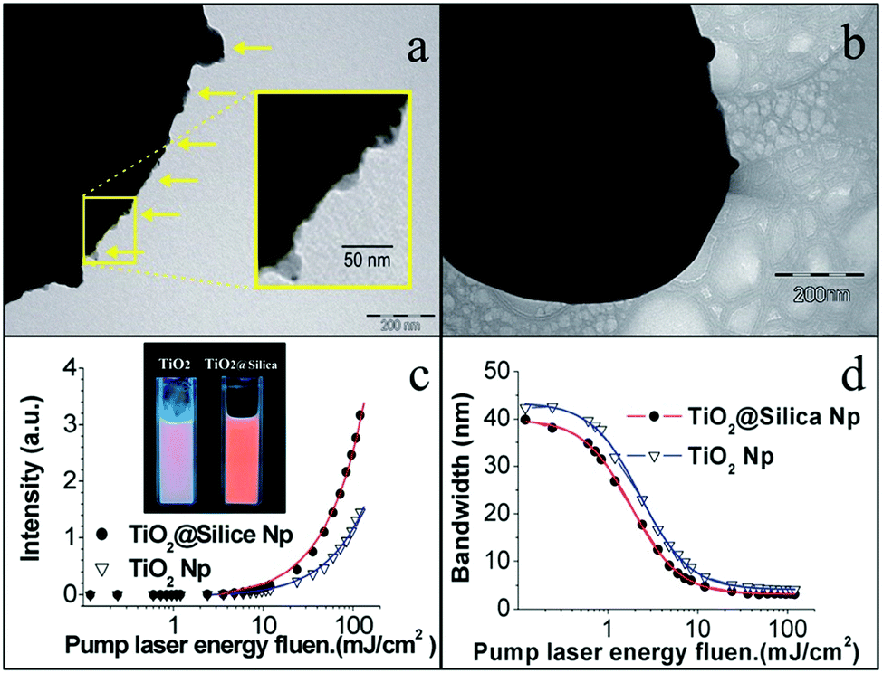 | ||
| Fig. 6 (a) TEM images of silica coating on the TiO2@Silica surface and (b) the surface of the TiO2 nanoparticle. The scale bars represent 200 nm. Yellow arrows (a) indicate the silica coating, and the inset in (a) is a magnification of the particle surface, framed with the yellow square. (c and d) Influence of the pumping energy fluence: (c) the emitted peak intensity and (d) spectral FWHM emission of the RL for the two kinds of nanoparticles (TiO2 and TiO2@Silica). Inset of (c): photograph of ethanol solutions of R6G containing nanoparticles of TiO2 and TiO2@Silica. The calculated particle density was 5.6 × 10¹⁰ Np ml−1 and [1 × 10⁻⁴ M] of R6G. The solid lines represent the fitting with experiments points. (Reproduced from ref. 96, with permission from [RSC Pub]). | ||
Dyes, doped with polymers, are an interesting active media. For example, PMMA is a ubiquitous and extensively used polymer. Versatile designs of dye-doped polymers, their synthesis, and device fabrication do not need advanced or new technological assistance, and it is a fascinating subject. However, polymers may have an inherent disorder due to their molecular structure or defects during processing. It is responsible for the multiple scattering of light.
Albuquerque De Oliveira et al. Studied the RL emission in electrospun polymeric nanofibers with R6G as the gain medium.87 The emission spectrum, SEM image, and schematic of different ways of incorporating dye are shown in Fig. 7. Choosing the polyvinylidene fluoride (PVDF) as RL flexible substrate, a thresholds tunable and stretchable polymer film RL was demonstrated by Dai et al.98 Compared with the flexible substrates used in previous works, the polymeric matrix PVDF possesses excellent thermal and hydrophobic stability and an increased break elongation index.
 | ||
| Fig. 7 Schematics of incorporating R6G, the gain medium of the studied RL, into the nanofiber matrix. (a) Conventional strategy: R6G solution is added to the polymeric mixture before performing electrospinning, leading to the molecules to be mainly inside the resulting nanofibers. The inset shows the RL emission spectrum for a pump energy of 100 μJ (blue line). (b) Drop-casting the R6G solution on the previously electrospun nanofibers, which causes the R6G molecules to be mainly adsorbed on the already existing nanofibers. The resulting emission spectrum for a pump energy of 100 μJ can also be seen in the inset of (a) (red line), which shows no RL action. (c) Sketch of the RL feedback mechanism in the case of the R6G molecules adsorbed on the surface of the nanofibers. The inset shows the resulting emission when the system is excited with 1200 μJ (more than 12× larger than the pump energy threshold), still showing some fluorescent background together with a RL emission peak. The results are for the sample CA + 10% PEO. (Reproduced from ref. 87, with permission from [RSC Pub]). | ||
Also, it is possible to add scattering particles deliberately if the polymer is inert. Polydimethylsiloxane (PDMS) and Tetraethylorthosilicate (TEOS) are two of them. The introduction of such randomness will result in enhanced scattering, and the group of Demetrios Anglos in 2004 experimentally demonstrated RL action in a system consisting of ZnO NPs dispersed in a polymer matrix that is optically inactive.99 Various sized Silver NPs were added to dye-doped polymer films for attaining enhanced random lasing by Shuya Ning et al.100 Lech Sznitko et al. published a great review of polymers’ importance on random lasing action in 2015.31
Carbon dots are materials that have a plethora of applications. They exhibit the surface plasmon effect, and Wei-Cheng Liao et al. exhibited the first controllable RL aided by the same.26 Gallium Nitride (GaN) nanorods are used as the gain medium, and Coherent feedback is provided by carbon dots derived from candle soot. Here carbon dots are produced via a conventional combustion oxidation method with oxidative acid treatment. Under optical pumping, vertically aligned nanorods show amplified spontaneous emission (ASE). Optical modes are controlled and realized by modifying the amounts of carbon dots. Moreover, the lasing threshold could also be tunable. These several exciting functionalities find application in optical communications.
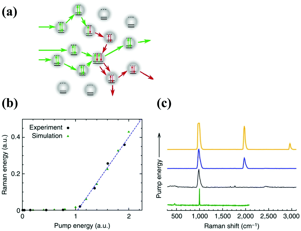 | ||
| Fig. 8 (a) Conceptual drawing illustrating random Raman lasing that is built up from spontaneous Raman scattering. Several pump photons are shown entering the medium. One undergoes spontaneous Raman scattering, whereas the other two are simply elastically scattered. An additional Raman photon is created via stimulated Raman scattering between the two elastically scattered pump photons and the Raman photon. This is the mechanism that drives random Raman lasing. (b) Output Raman pulse energy versus incident pump pulse energy indicating a clear threshold where random Raman lasing begins. Black circles are the experimental data points, dashed blue line is a linear fit of the last four experimental data points and green triangles are the results of Monte Carlo simulations. (c) SRS spectra of BaSO4 powder at various pump powers illustrating the presence of higher-order Raman transitions. The spontaneous Raman spectrum of BaSO4 is shown for comparison, but was taken with a much higher resolution spectrometer. All spectra have been normalized to fit on the same scale, and the widths of the SRS spectral peaks were limited by the resolution of the spectrometer used. a.u., arbitrary unit. (Reproduced from ref. 101, with permission from [Springer Nature]). | ||
In 2017, they established it as the light source with a narrowband for speckle-free imaging. It is one of the most remarkable applications of RL. They also image cavitation dynamics from water in the nanosecond regime.102
4.2. RL based on multiphoton excited emission
Multiphoton absorption and energy transfer mechanism are utilised to investigate upconversion RLs. Two or more photons are absorbed together or sequentially in a multiphoton upconversion. It causes spectral emission with higher energy than the pumping energy. The multiphoton absorption occurs sequentially. The pump photon absorbs the energy linearly and goes to a metastable state. Then this is accompanied by more absorption or excitation through the transfer of energy. It will make the ion reach even higher excited states and emit upconverted anti-stokes photons. In 2014 Gomes et al. studied three-photon assisted upconversion RL in a regime with very weak scattering. This paper is the first reported RL emission in a colloidal dye solution by direct three-photon excitation in the NIR.103They used an excitation wavelength of 1350 nm (near IR), and the emission at 560 nm. The emission spectrum contains spikes of linewidths approximately equal to .4 nm. In 2009 Marcos A. S. de Oliveira et al. reported an ultraviolet RL action in the neodymium-doped powder of fluroindate glass.104 They used an excitation wavelength of 575 nm, which is in resonance with the transition of Nd3+ (4I9/2 to 2G7/2) and achieved an RL threshold of 30 kW cm−2. Two-photon Antistokes upconverted RLs were experimentally demonstrated in various media such as ZnO,105 GaAs46 powders, and colloidal dye solutions. A. Burin et al. explained that a two-photon excitation mechanism is theoretically an efficient and effective pumping or excitation mechanism for random lasing action.106 In 2019, Jiao Tian et al. published an article107 in which they described the ultraviolet RL emission in ZnO nanopowders depending on multiphoton absorption. They obtained upconversion random lasing when the excitation wavelength changes from 600 nm to 1800 nm, corresponding to five photon excitations. They have attained a pulse with a decay life and width of 1.9 and 2.6 picoseconds. These all indicate a quality upconversion random lasing, which could be employed in ultrafast upconversion lasing devices.
5. Advanced materials for enhancing the performance and properties of RLs
The applicability of RLs has been restricted due to emission in random directions, difficulties in tuning polarization and wavelength, and intense competition of modes with chaotic fluctuations due to inadequate mode confinement. This section will discuss the recent progress and prospects of using advanced materials to address these limitations with random lasers.5.1. RL with Controllable wavelengths. Multi-colour random lasers: from dye to monochromatic polymer film mixtures
Xueyang Li et al. Recently reported a tunable and flexible RL using a substrate called PDMS.76 The structure of the lotus leaf is the inspirational factor of this work. They cast structures by a method named soft lithography. The substrate had a micropapilla structure, and the Lotus leaf has almost a similar framework. Mengnan Hu et al. recently Published a new RL that could be tailored with humidity.71 In this article, they used materials such as glycerine and chitosan as water absorbers. Here the gain is provided by R6G, and optimum feedback is given by silver Nanoflowers (scatterers). All the materials mentioned above house in a film on a substrate (glass). The emission spectra are regulated by a humidity modification, which in turn, through water adsorption. This type of RL can be used as a humidity sensor since humidity can control its output.White light generation is a remarkable trend in replacing conventional incandescent and fluorescent lamps. Shujingchen et al. in 2012 reported an intensity feedback emission of white light from a disordered medium. They use a mixture of three dyes in ethanol as gain material and TiO2 NPs as scatterers. The energy transfer mechanism occurred between the dyes during the excitation with a wavelength of 355 nm. The pump Beam excited two dyes (Coumarin 440 and coumarin 6), and the third dye (Oxazine) was excited by a part of the peak of coumarin 6.108 Moreover, Shu-Wei Chang et al. in 2018 manifested a mixture of three organic dyes and flexible polymers to realize white RL.109 Here the authors used self-assembled approaches to fabricate monochromatic polymer films (MPFs).
They synthesized red, green, and blue MPFs, and random lasing measurements were taken using a pulsed Nd: YAG laser with a wavelength of 266 nm. This work as white RL attributed to more excellent stability and purity. The construction of self-assembled laser resonators with different sizes and distributions presents RLs’ further possibilities for large-scale fabrication and roll-to-roll printing. Notably, the lasing characteristics of White-RL are independent of the angle of observations, which is an incredible feature of the white RL scheme. S F Haddawi et al. recently introduced the first tunable and low-power RL based on piezo plasmonic NPs.110 The core/shell structure consists of lead zirconate titanate and gold combined with various dye concentrations (rhodamine B). Coherent random lasing was observed when applying an external voltage, and emission intensity enhancement was witnessed at a lower threshold pump power.
5.2. RL with Controllable directions
A recent article demonstrates a directional RL emission using GQDs as scattering particles.68 A thin layer of liquid dye (Rhodamine B) with GQDs is placed between two microscope glass slides indicated in Fig. 9.
 | ||
| Fig. 9 A thin layer of liquid dye (Rhodamine B) with GQDs is placed between two microscope glass slides. (a), (b) A double sided tape is stuck to a microscope glass slide; (c) Several droplets of dye solution containing GQDs with certain volume are deposited in the middle of double sided tape; (d) The solution is distributed uniformly in the empty space at the middle of the double sided tape; (e), (f) Finally, another microscope slide is placed on the double sided tape and by pressing of it the RL cell is obtained. (Reproduced from ref. 68, with permission from [Elsevier]). | ||
This structure of RL serves the purpose of waveguiding. This article provides an easy and cost-effective resonant RL system. Paul Bouteyre et al. observed Directional RLs from a polycrystalline thin film of perovskite embedded in PMMA. It can control the emission by coupling it with cavity polaritonic resonance.120 Hee-Won Shin et al. published a directional RL employing porous alumina membrane loaded in the nanochannels with hybrid polymer nanowires.121 The group used R6G as the gain medium and TiO2 as scatterers, and the entire structural peculiarities of the active material make it explore a directional RL. The angle-resolved photoluminescence analysis implied that lasing had a remarkable directionality along the hybrid polymer nanowires buried within the membrane's nanochannels.
Directional coherent random lasing was achieved by Eunice S. P. Leong group from p-GaN/i-ZnO–SiO2 nanocomposite/n-ZnO heterojunction diodes.122 Generally, low refractive indexed material is utilized for cladding layers and relatively high refractive indexed for the core layer, with stripes of ZnO clusters providing transverse confinement. The output emission of the RL could be realized from the edges of the diode. Random fiber lasers were introduced due to their unique attributes of high lasing efficiency and directional output emission.123–127 Songtao Li et al. utilized a polymer fiber waveguide and silver plasmonic feedback for exploring a low threshold directional RL.128 Here they used a straightforward and effective fabrication method devoid of spin-coating and annealing. The length of the polymer fiber affected the output's intensity, opening up a new avenue of miniaturization of laser devices. A directional random lasing emission exhibited by Behnam Abaie et al. works in the Anderson localization regime.129 The disorder-induced localized states of glass optical fiber form isolated local channels that produce extremely directional and stable output laser beams.
In recent years, random lasers have been developed using liquid crystals as a scattering material. As a typical anisotropic material, they present unique opto-electronic properties. In particular, nematic liquid crystals (NLCs) allow a convenient scattering medium for RL emission. Combining solitons and collinear pumping in dye-doped NLCs can establish random lasing with enhanced characteristics. One of the most significant benefits of NLCs is their response to external stimuli operating on director distribution. Hence, tuning optical properties such as refractive index, anisotropy, etc., can be done using electromagnetic perturbations,130 which affect the propagation of nematicon. The stimuli comprised of applied voltage,131–135 magnetic field,136 refractive index perturbations130 and external light beams.137–139 Sreekanth Perumbilavil et al. reported the nematicon-aided random lasing in liquid crystals.140 They used nematic Liquid Crystal based planar cells [PC] with 0.3 wt% dye to achieve random lasing (Fig. 10). Fig. 10a and b exhibit the geometry of the sample and set-up of the experiment. To create a soliton in a PC carrying NLC doped with dye, a near-infrared (NIR) beam was propelled through the z-axis, including a linearly polarized field in the yz plane; To maximize the optical nonlinearity, n (molecular director distribution, also called optic axis) was arranged at 45° in the same plane with the z-axis. An ordinary green wave at 532 nm with an electric field parallel to the x-axis was used and injected along the z-axis to pump the medium. Two rays (Green, NIR) were directed and converged in the same place with more or less equivalent waists (∼3 μm), and the resulting fluorescence and stimulated output are co-polarized and trapped by the nematicon.
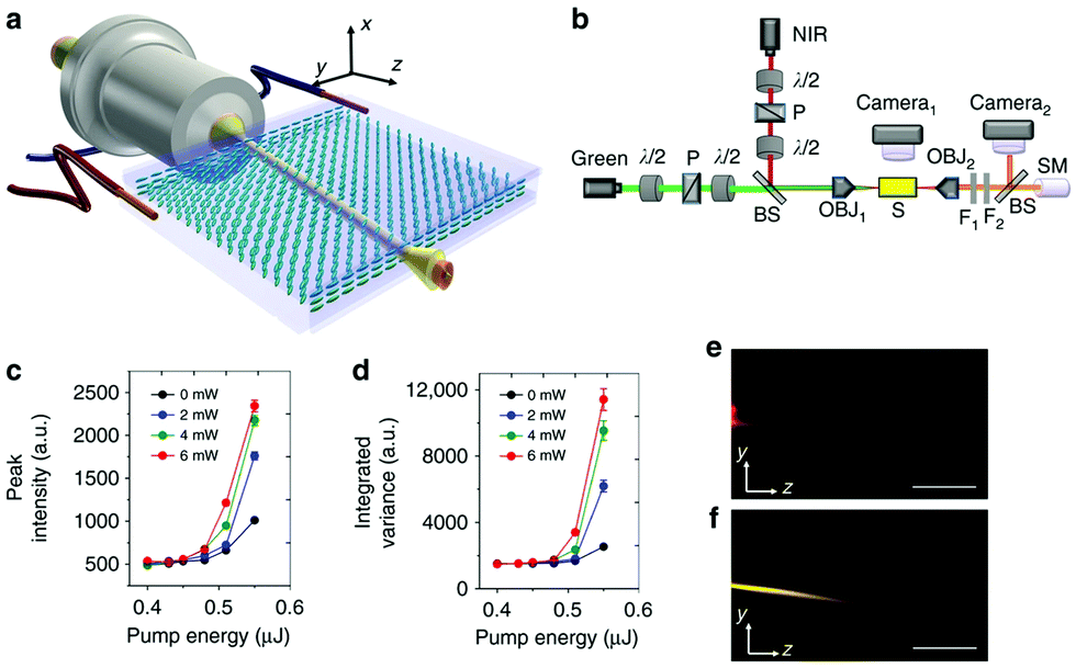 | ||
| Fig. 10 Configuration and basic features of nematicon-assisted random laser. (a) Planar cell configuration and orientation. Here, the two wires allude to the application of a bias voltage across the cell thickness (see Methods). The molecular director distribution n (optic-axis) is represented by blue ellipses. (b) Sketch of the basic experimental set-up, with green pulsed pump and continuous-wave near-infrared (NIR) lasers, microscope objectives (OBJ) to inject and collect light, beam splitters (BS), polarisers (P), waveplates (λ/2), notch filters (F1 and F2), spectrometer (SM). (c) Typical input–output random laser characteristics for various soliton powers and an ordinary-wave pump, from the mean peak intensity. The legend indicates the input power of the near-infrared nematicon. (d) As in (c) but from the integrated variance σI2 of the averaged spectra over 200 gated acquisitions (in 100 ms windows), carrying out the analysis. The error bars in (c) and (d) correspond to standard deviation over 200 acquisitions. (e) Photograph of emitted random laser light in the yz plane for a pump energy E = 0.55 μJ, without nematicon. (f) As in (e) but in the presence of a 6 mW nematicon (the near-infrared was filtered out). The scale bars indicate a length of 500 μm (Reproduced from ref. 140, with permission from [Springer Nature]). | ||
Fig. 10f indicated the nematicon propagation at an angle of 7° off z due to birefringent walk-off; Thus, the soliton could collect, guide, and influence the development of lasing modes in the extended volume along the longitudinal direction, enhancing RL directionality and profile. However, RL steering for large angles is quite challenging. So, they found an alternate way by using the NLC's response towards external magnetic fields. This applied magnetic field can efficiently reorient the molecular director and regulate the soliton trajectories. Here the field given is sufficient to align the NLC to the entire volume of interest. Output emission of RL can be directed utilizing external low-frequency voltage and a moderate magnetic field. However, RL output's magneto-optic steering was more effective than voltage-controlled steering since emission efficiency depends less on the applied field.
Fig. 11 Indicates the direction of n with and without a magnetic field. Under zero magnetic field (B = 0 mT), ‘n’ is in the direction of rubbing of LC cell (R). With an application of B ∼ 50 mT along with R, ferromagnetic domain walls could be recognized because of the magnetic rearrangement of the nematic director.
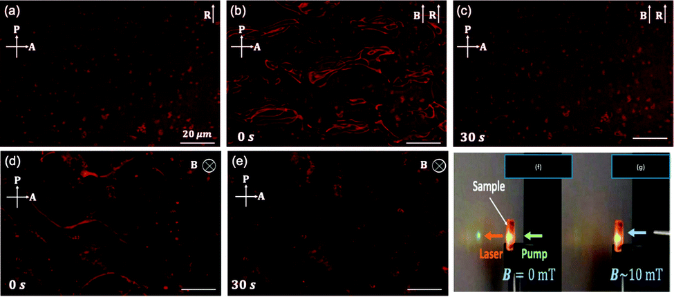 | ||
| Fig. 11 Switching of ferromagnetic domains in pDFNLC (DFNLCs in a PAC)in external magnetic fields as seen by polarizing microscopy. The images seem to be bright because of the fluorescence of the dye. (a) Without a magnetic field (B = 0 mT). Polarizing micrographs were taken under a magnetic field (B ∼ 50 mT) along R from (b) 0 s to (c) 30 s after application of the field. Polarizing micrographs under a magnetic field (B ∼ 50 mT) normal to the cell plane from (d) 0 s to (e) 30 s after application of the field. Magnetic switching of random laser action in pDFNLC. (f) The random laser emission is spotted on the screen. (g) The random laser emission was extinguished when the magnetic field was applied normal to the cell plane. (Reproduced from ref. 49, with permission from [Optica Publishing Group]). | ||
It signifies that an external magnetic field can control the RL action in FNLCs. Fig. 11a depicts RL output on the screen without any magnetic fields. The spotted RL emission was immediately destroyed when a B field of approximately 10 mT was used normal to the plane of the cell, as presented in Fig. 11f and g. This article explores switching off the RL action between normally open and closed modes. Cheng-Yen Tsai et al. invented, built, and demonstrated magnetically controllable RL (MCRLs),141 and it is made of a laser dye and scatterers (TiO2 + Fe3O4 NPs) that can be controlled magnetically. Other exotic works also use magnetic nanoparticle scatterers to control and observe random lasing emission.142,143
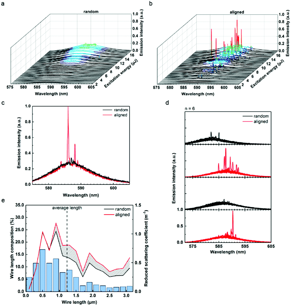 | ||
| Fig. 12 Reconfigurable lasing response. Emission spectra and calculated reduced scattering coefficients of randomly oriented nanowire/dye suspensions versus horizontally assembled nanowire/dye suspensions. (a) Plot of emission spectra of randomly oriented nanowires as excitation energy is increased. (b) Spectra collected from the same sample at the same pumping energies while wires are aligned. (c) Spectra depicting assembly facilitated transition from fluorescence (black) to lasing (red). Both spectra were collected from the same location of a sample, before and after particle alignment. The absorption cross-section dominates the scattering cross section at the pump wavelength. As a result, the fluorescence background levels for aligned and unaligned wires are nearly identical. (d) All spectra shown are collected from a single sample of TiO2 wires (2.16 × 10⁸ wires per ml) suspended in rB (rhodamine B) EG (ethylene glycol) solution (2 mM). Each plot displays six spectra (initial conditions correspond to top spectra set) obtained from several sample locations. Wire alignment conditions were cycled between unassembled (black) to assembled (red). Ability to turn lasing on/off repeatedly shows robustness of the response. (e) Calculated reduced scattering coefficient plots (black line, randomly oriented wires; red line, wires aligned via applied field) dependent on the heterogeneous wire lengths of sample (blue bars). The shaded region between lines represents the increase in reduced scattering coefficient due to assembly. (Reproduced from ref. 149, with permission from [American Chemical Society]). | ||
Electrically controllable RLs have great significance and have not been explored much.53,152 Wang et al. fabricated an electrically controllable plasmonic enhanced coherent RL from the dye-doped NLC containing the Au NPs in the thin LC cells. Analysis of the output spectrum showed that the improvement of the localized electric field in the proximity of Au NPs is due to the localized surface plasmon resonance (LSPR).152–157 LSPR is furthermore efficient in enhancing the lasing efficiency than increasing the scattering strength of the medium.
All these conclusions symbolize that NPRL holds all-optically reversible controllability. i.e., RL output has a gradual decay and rises back all-optically. All these effects are due to the presence of Azo-dyes, and it's all optically controllable molecular confirmation. When Azo-dyes are irradiated with long and short wavelengths, their structure has an exchange transition between two states (rod-like trans-state and Curved cis state).160–163 Azo dyes are usually in a trans-state in the dark, and they absorb UV beams and transform to the curved cis state through trans–cis isomerization. In addition, azo dyes interact with the host (LC) and laser dyes.
When the UV irradiation time increases, the concentration of 4MAB dyes increases due to trans cis isomerization so that there will be an isothermal increase in the randomness of LDDLC. Then, suppose we increase the irradiation time of the green beam (UV light kept off), and the concentration of trans dyes increases. In that case, a subsequent isothermal increase of order (reverse of the process as mentioned earlier) will occur. This achievement of getting all optically controllable NPRL is due to the induced decrease (UV-irradiation) and increase (green-beam) in the order of LDDLC by their interactions with different structures (bend and rod) of Azo dyes. Successive illumination of UV and green light can decrease and increase the absorption of the laser dye and hence the induced spontaneous emission, respectively. It, in turn, results in the reduction and increase of the NPRL output emission on top of the fluorescence curve through multi-scattering of the NPs inside the LDDLC cell.
5.3. Polarization controlled random lasers
The polarization state of the emission spectrum is another important characteristic for RLs. Gottardo et al. exploited the advantage of small droplets of liquid crystals displaying extremely anisotropic scattering to create and manipulate polarized random laser emission.164 Using the anisotropic adsorption of the dye molecules is also a strategy to provide linearly polarized random lasing.165 Finally, laser emitted from dye-doped nematic liquid crystal (DDNLC) cell providing arbitrary linear polarization of RLs by rotating the nematic liquid crystal sample.166 Interestingly, tunable polarizing direction of random lasing emission by an applied electric field which radiated from the lateral end face of homogeneously aligned, dye-doped nematic liquid crystal cell was demonstrated by Yao et al.167Recently the realization of random lasing with a high degree of circular dichroism with the aid of chiral plasmonic gold nanoparticles was demonstrated.51 An optimal inclusion of the chiral plasmonic gold nanoparticles to an ethylene glycol solution of R6G laser dye molecules mixed with dielectric titanium dioxide nanoparticles was found to result in the laser emission having a considerably high level of asymmetry between the right- and left-handed circularly polarized light, reaching luminescence dissymmetry factor of 0.20–0.23.
6. Applications
6.1. RL-based sensors and speckle-free imaging
Temperature-sensitive displays and remote temperature sensing are some of the applications of RLs. For instance, Wiersma et al. reported a temperature tunable RL.168 The sensitivity of RLs towards temperature is the reason for using them as sensors. Moreover, it may find application in sensing the pH by a biocompatible RL169 (Fig. 13). It indicates a pH sensing scheme of random lasing.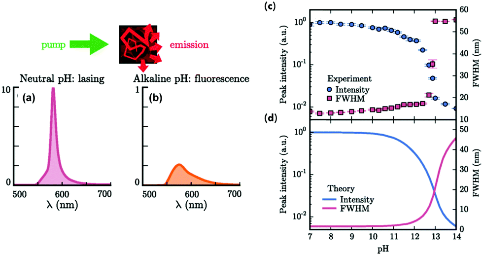 | ||
| Fig. 13 Random-lasing sensing scheme. Light multiple scattering in the gain medium embedded in a photonic glass leads to amplification and lasing. This result is experimentally visible in the emission spectrum which shows a narrowband emission [the red line in (a)]. For alkaline pH, the lasing emission is switched off, resulting in the broadband fluorescence emission and the lower intensity [the orange line in (b)]. Sensing of pH: a comparison of experiments and theory. (c) The random-lasing system is pumped above the lasing threshold (P = 840 μJ mm−2) and the emission characteristics as a function of the pH of the solution are recorded. The lasing is suppressed at large pH values (pH > 13), corresponding to a strong decrease of the peak intensity (the blue circles) and a sharp increase of the FWHM of the emission (the red square). (d) Theoretical prediction of the lasing response upon pH variation, which shows a similar behaviour. (Reproduced from ref. 169, with permission from [American Physical Society]). | ||
Here the RL system is fabricated using inverse silk photonic glass embedded R6G. The figure showed an exact difference in the spectra under neutral and alkaline environments. These theoretical predictions by utilizing a dispersive diffusive lasing model could explain the sensing dynamics, and It is in good agreement with the experimental data. This work by M. Gaio et al. exhibited the RL-based pH sensor, far better than conventional fluorescence sensors. RLs can also be exploited as biochemical sensors. Here biological or chemical components in the vicinity of the stimulated emission line may change the refractive index or introduce absorption loss, leading to a slight frequency shift. Since the peaks of RLs are narrow, this frequency shift can be detected easily.
Speckle-free bioimaging is a potential application of paramount importance. Two vital features of RL are brightness and low coherence.14,170 Due to these properties, speckle-less imaging is possible. In the case of conventional lasers, interference patterns constructed between several wavefronts occurred due to their high coherence. It gave us images that contain speckles, whereas other light sources (low coherence) like LED, they have a very low number of photons per coherence volume. To obtain high-resolution single-shot images with uniform background and low speckle noise, a low spatial coherence pulsed source is developed based on a random lasing effect. The bright low-coherence narrowband illumination source can acquire high-quality speckle-free images, providing at the same time information on the amplitude and the phase of the object. This illumination method significantly increases the image's dynamical range and signal-to-noise ratio, allowing us to take full advantage of the optical resolution of the microscope with time resolution. The electronic synchronization between the ultrafast laser system and the ns laser system ensures the time-synchronization between the exciting ultrashort laser pulse in liquids and the random lasing illumination (probe) source. The excitation region in the liquid sample is imaged in a perpendicular geometry. The probe enters the illumination path of the microscope via the microscope condenser and the optical transmission. Thus, phase-contrast microscope images are recorded in the image plane with the back-illuminated electron multiplier EMCCD. An overview of the bubble cavitation dynamics in different conditions related to the input laser pulse energy, laser pulse duration, and liquid viscosity is given in Fig. 14. The images show cavitation dynamics in the vicinity and well above the cavitation threshold, emphasising particular features from the pulse duration and the liquid viscosity. In this context, the speckle-free pulsed imaging technique offers an outstanding visualisation quality of both amplitude and phase details of the evolving object.
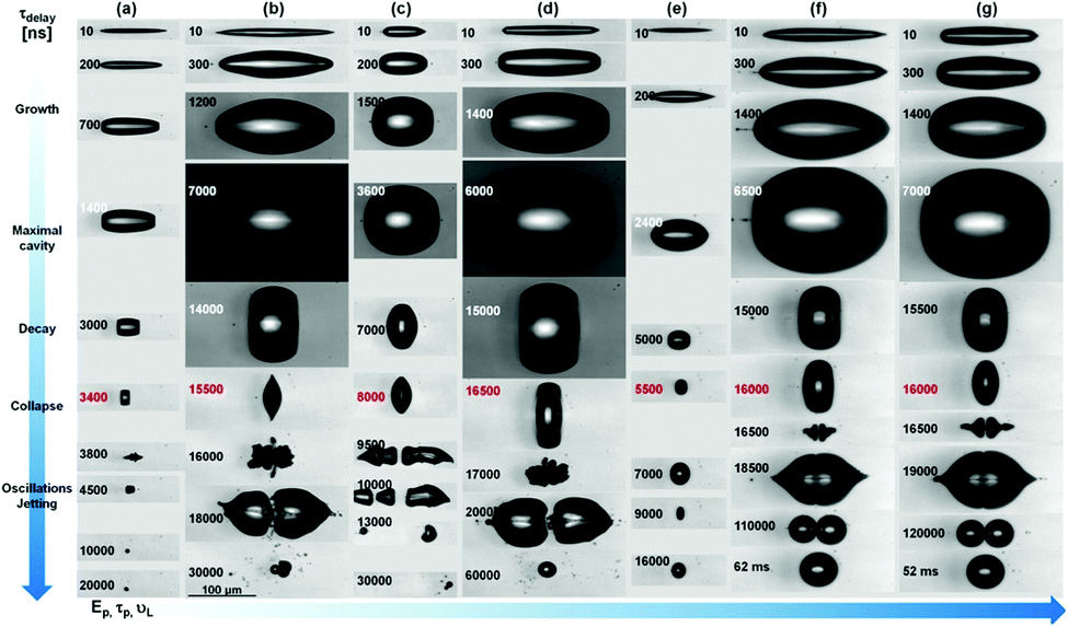 | ||
| Fig. 14 Two-color pump–probe time-resolved microscopy technique using a random laser as probe laser. A kaleidoscope of cavitation collapse phenomena resulting in directional jetting, bubble stabilization, or fragmentation can be obtained. (Reproduced from ref. 15, with permission from [Springer Nature]). | ||
6.2. Medical applications and display technology applications
RLs are utilized in many fields. This technology has a variety of potential applications in medicine. Dermatology, medical imaging, and photodynamic therapy are areas that explore RLs in the medical field. High energy density emission and reasonably narrow linewidth made the RL application possible in medicine.56,171Dopamine is a “feel-good” neurotransmitter, and RLs can be used as dopamine sensors.172 In photodynamic therapy, drugs are initially attached to the target cells and are activated via an RL light source. Removal of unnecessary tattoos on the skin is a significant application in dermatology. Polson et al. reported RL emission from dye infiltrated human tissues. They also observed that cancerous or malignant tissues showed more spectral lines than healthy tissues depicted in Fig. 15.32 In turn, it paved the way for diagnostic imaging and enabled an additional method for tumour diagnostics. Qinghai Song et al. in 2010 detected structural changes in the bone tissue at nanoscales using RLs.173 In 2010, R C Polson and Z V Vardeny reported cancerous tissue mapping via random lasing emission spectra.11
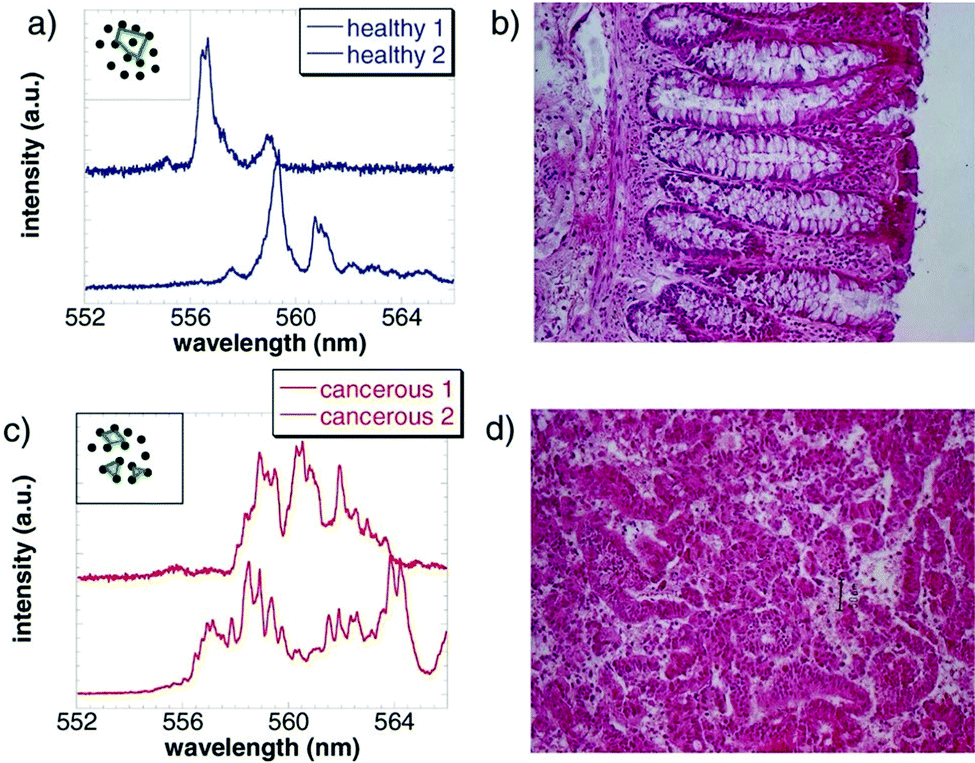 | ||
| Fig. 15 Random laser emission spectra of human colon tissues infiltrated with a concentrated laser dye, namely R6G. (a) Two typical random laser emission spectra from a healthy, grossly uninvolved tissue (blue), of which microscopic image is shown in (b). The narrow spectral lines are in fact coherent laser emission modes. The inset shows schematically closed random laser resonators formed due to scatterers in the gain medium. (c) and (d), same as in (a) and (b), respectively, but for a malignant colon tissue. There are more lines in the emission spectra in (c)(red) that are due to the more significant number of resonators in the tumor; these are generated by the excess disorder that is apparent in (d). (Reproduced from ref. 32, with permission from [AIP Publishing]). | ||
By integrating a random laser system with the scarab beetle's elytron as a biocompatible (substrate), Seungsu Lee et al. examined circularly polarised light's angular distribution by evaluating the luminescence dissymmetry factor (glum).174 Polarization-dependent studies were analyzed using scarab beetle with right/left-handed circular polarizer (RCPR and LCPR) and with no polarizer in front of the camera. Fig. 16A and B show images of the scarab beetle using different polarizers and the experimental set-up. Beetle seems dark and green using RCPR and LCPR (or no polarizer in this case), respectively. By exploiting this property, they use it as a chiral substrate. Further, the circularly polarized output emission from an RL is realized since the surface of the elytron exhibits chiral structure and, thereby, circular dichroism.
 | ||
| Fig. 16 Panel (A): Images of the scarab beetle C. gloriosa taken with (a) an LCPR, (b) no polarizer, and (c) an RCPR placed in front of the camera. Optical microscope images and scanning electron microscope (SEM) images of (d–f) green and (g–i) gold-colored areas of the beetle C. gloriosa. A corresponding scale bar is shown in each figure. Panel (B): arrangements for experiments and measurements: (a) Schematic of the experimental set-up. BD: Beam dump; ND: Neutral density filter; PBS: Polarizing beam splitter; M: Mirror; L: Focusing lens; NF: 532 nm notch filter; LCPR/RCPR: Left-/right-handed circular polarizer. The inset shows a schematic of the circularly polarized light-emitting random laser system. (b) The XYZ coordinate system showing the pump illumination angle θyz,p and the two emission measurement angles θyz,e and φxz,e(Reproduced from ref. 174, with permission from [Optica Publishing Group]). | ||
Display and lighting technology is an excellent application of interest. One of the features of an RL is that it is multidirectional. This advantage is used in display technologies. The display panel can be coated using a thin film of disordered media doped with emitters. Pattering RGB (red, blue, green) arrays using an RL is quite challenging. So Yue Hou et al. explored random lasers for making flexible displays.175 They introduced a fabrication strategy for random laser-based flexible display panels. So to achieve pixelated RL arrays, they utilized the technique of microtemplate- assisted inkjet printing. The PDMS microtemplates were made by casting PDMS into a silicon mould with convex cylinder arrays.
The combination of perovskite nanocrystals and SiO2 serves the purpose of an random lasing medium. Then it is dispersed in a mixture of toluene and 1-octadecene. Then it is injected into blank microtemplates using a hollow glass needle, and RL arrays are achieved after drying. The complete process is depicted in Fig. 17. Selectively exciting microlasers can realize emission spectra of several subpixel combinations in a single pixel. As the pump beam is focused on the microstructure doped with CsPbCl1.5Br1.5, CsPbBr3, and CsPbBrI2, the output spectra are dominated by blue (B), green (G) and red (R), respectively. Fig. 17b and c indicate different pixel patterns of the RGB microlaser array.
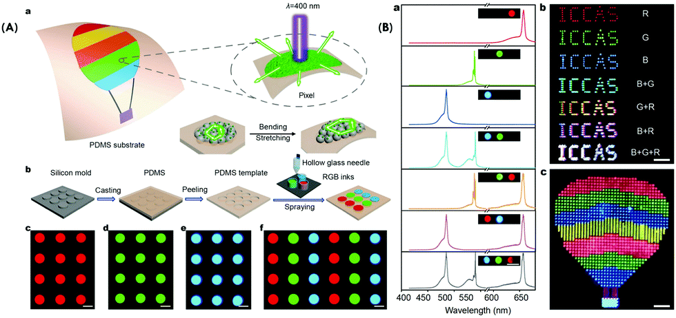 | ||
| Fig. 17 Panel (A): Design and fabrication of the flexible random laser arrays. (a) Design principle of the flexible laser display based on random lasers. (b) Schematic illustration for the fabrication of periodic RGB pixel arrays via microtemplate-assisted inkjet printing. (c–f) Fluorescence microscopy images of the periodic pixel arrays comprising red, green, blue and RGB emissive arrays under UV light radiation (330–380 nm). All scale bars are 50 μm. Panel (B): Full-color tunable lasing. (a) Lasing spectra and corresponding PL images while selectively exciting the different microlasers above their thresholds. From top to bottom: R, G, B, B + G, G + R, B + R, and B + G + R emissive microstructures. The scale bar is 100 μm. (b) Far-field photograph of the “ICCAS” patterns of pixel arrays comprising different microlasers, showing R, G, B, B + G, G + R, B + R, and B + G + R lasing emission, respectively. The scale bar is 800 μm. (c) Far-field photograph of a hot air balloon pattern with a 40 × 44 pixel array on a PDMS substrate. The scale bar is 700 μm(Reproduced from ref. 175, with permission from [Springer Nature]). | ||
Also, high-speed displays have gained much attention this year. Switching RLs to an on and off position is much faster than regular LEDs (Light-emitting diodes). Moreover, emitters of different frequencies are embedded in the random media a multi-colour display can be achieved. In addition, RL can also act as an active element in photonic devices and circuits.
6.3. Biological applications
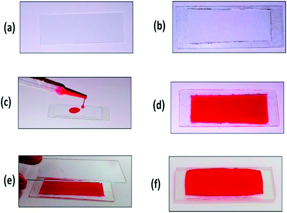
Fluorescent colloidal silica NPs are widely used for diagnostics, and therapeutic applications, particularly cancer detection and drug delivery.176,177 Van Duong Ta et al. showed effective random lasing from microslices comprising dye-doped colloidal silica NPs synthesized using the self-assembly method.74 In addition, they demonstrated the notion of an RL proficiently operating in the porcine skin tissue (Fig. 18).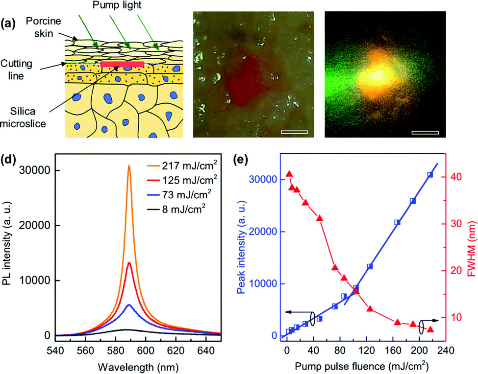 | ||
| Fig. 18 (a) Schematic of random lasers implanted into the skin. (b) Optical microscope image of a laser embedded below the porcine skin surface. (c) PL image of the sample upon optical excitation. (d) Emission spectra of the embedded laser sample at various pump fluences. (e) Peak intensity and FWHM of emission spectra versus pump fluence. (Reproduced from ref. 74, with permission from [Elsevier]). | ||
Implantable lasers are essential for biological applications. Among several of these kinds, RLs are the least explored ones. This microslice RLs class can be operated well in several media, including water, air, and, more importantly, skin tissue. These lasers have dimensions of about 100–200 μm and a thickness of 2 μm. The lasing features in all circumstances are alike, excluding the lasing threshold, which is smallest in air and highest in the porcine skin. The biocompatibility of silica, these lasers are reliable for incorporating into diverse biological components such as blood and tissue, which have potential applications for bioimaging and sensing and are also used as probes for biological samples.
6.4. RL Action in Memories
Scaling is a critical issue in nanoelectronics. Two types of memories can be addressed; volatile and nonvolatile memory. Nonvolatile memories178,179 employ a resistance element that can be switched electrically and maintain original data without expending energy even when the power is switched off. Therefore, resistive random-access memory (RRAM) technology is one of the most assuring and credible alternative solutions to surmount the scaling dilemma. A relevant RRAM device is conductive-bridging random access memory (CBRAM), which has a high potentiality to fulfil the necessities for next-generation nonvolatile memory (NVM) technology. Yu-Ting Cheng et al.72 reported silver NPs (scattering centers) agglomeration and form metal filaments via electrochemical metallization (ECM) process180 in the insulating layer. The insulating layer is composed of PMMA and CdSe/ZnS colloidal core−shell QDs during the ON/OFF switching process. The switching of RRAM from high resistance (“0” state) to low resistance (“1” state) was controlled by the agglomeration of silver nanoparticles under external bias. Spectra show off state, indicating that the system behaves as if there are no Ag nanoparticles. Also, the spectra exhibit aggregation or presence of Ag nanoparticles after switching (on state). The emission wavelength can be changed by controlling the size of the quantum dot. When pumping power is above the threshold, the vast difference in spectral shape can identify the OFF/ON-states. The speed of series data transmission is low when read electrically. One of the alternatives is to use the optical parallel transmission method to read signals which are encoded. Here utilizing the concept of random lasing, RRAM can concurrently read the encoded signal electrically and optically.7. Challenges and prospects
RLs are still a growing field, and there is more to explore. Apart from such a laser's complexities, this can be used in diverse areas as a potential candidate for various applications ranging from medical to security. Also, exciting the active media through electrical pumping and incorporating this with flexible structures can create portable RL for low power consumption for bioimaging. The concept of random lasing will indeed create wonders and open new avenues for photonic device fabrication. Both bottom-up and top-down methods can be used as a synthesis protocol, and applying random lasing in the medical field gave hope to economically sophisticated instruments soon. The polymer's exceptional structural, physical, and chemical characteristics are promising materials for making versatile and low-cost random lasing devices. In addition, the recent developments in 3D printing181 will permit to push RLs applications in optomicrofluidics, photonics circuits, implants, etcRLs applications in optomicrofluidics, photonics circuits, implants, etc. There is still room for many other alternatives for exploring this emerging research topic for the future development of cost-effective and biocompatible optoelectronic devices. Innovative synthesis for targets based on nanocomposites serving as both the gain and the scattering media must be developed. For instance, by integrating metamaterials with highly luminescent metal nanoclusters, strong random lasing may be explored.63 Indeed, luminescent silver nanoclusters can emit photons under linear and nonlinear optical rergimes,182 with wavelength tunability from the picosecond and sub-microsecond regimes.183 The other important, challenging task will include developing innovative technologies for directionally controlling random laser emissions. For this purpose, innovative directional confinement components may be introduced into the random lasing system. Confinement components based on hybrid polymer nanowires184 might be introduced into the random lasing system to allow for emission direction along the long axis of the nanowires. And the combination of highly luminescent silver nanoclusters electrostatically or covalently bound to 2D matrices (such as graphene oxide nanosheets,185 as in Fig. 19186,187 might lead to the next generation RLs designs.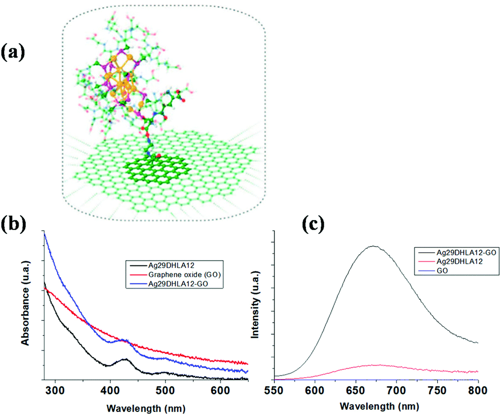 | ||
| Fig. 19 Schematic view of the graphene oxide-nanocluster interface. (a) The nanocluster is Au15SR13 (SR: thiolated molecules) covalently bound to graphene oxide. (b and c) absorption and emission spectra of silver nanoclusters electrostatically bound to graphene oxide nanosheets. adapted (Reproduced from ref. 187, with permission from [IOP Publishing, Ltd]). | ||
Abbreviations
| Ag NFs | Silver nanoflowers |
| Ag–TSA MNC | Silver metal nanoclusters |
| ASE | Amplified spontaneous emission |
| CBRAM | Conductive-bridging random access memory |
| DDNLC | Dye-doped nematic liquid crystal |
| DDPDLC | Dye-doped polymer-dispersed liquid crystal |
| DFNLCs | Dye-doped ferromagnetic NLCs |
| DNLCs | Dye-doped nematic liquid crystals |
| ECM | Electrochemical metallization |
| FNLCs | Ferromagnetic nematic liquid crystals |
| GQDs | Graphene quantum dots |
| HAC | Homeotropic alignment cells |
| HMM | Hyperbolic metamaterials |
| LA | Amplification length |
| LG | Gain length |
| LT | Transport mean free path |
| LCPR | Left-handed circular polarizer |
| LDDLC | Laser-dye-doped liquid crystal |
| LSP | Localized surface plasmons |
| LSPR | Localized surface plasmon resonance |
| MCRLs | Magnetically controllable RLs |
| MNCs | Metal Nanoclusters |
| MPFs | Monochromatic polymer films |
| NA | Nanorod arrays |
| NLCs | Nematic liquid crystals |
| NPRL | Nanoparticle random laser |
| NPs | Nanoparticles |
| PAC | Planar alignment cells |
| PDMS | Polydimethylsiloxane |
| PMMA | Polymethyl methacrylate |
| PVDF | Ployvinylidene fluoride |
| QDs | Quantum dots |
| R6G | Rhodamine 6G |
| RCPR | Right handed circular polarizer |
| RL | Random laser |
| RRAM | Resistive random-access memory |
Author contributions
P. K. Nideesh: Term, conceptualization, methodology, validation, formal analysis, investigation, data curation, writing - original draft. S. Thomas: formal analysis, writing – review & editing. R. Antoine: formal analysis, writing – revised draft – review & editing, conceptualization, methodology. N. Kalarikkal: term, conceptualization, methodology, resources, formal analysis, investigation, writing – review & editing, supervision.Conflicts of interest
There are no conflicts to declare.Acknowledgements
We acknowledge the financial support from BRNS-DAE, Govt. of India, DST for funding through INSPIRE scheme, PURSE PII, FIST and Nano Mission programs, UGC, Govt. of India for funding through SAP-DRS and Innovative program, SAIF-MGU. We also acknowledge Dr Sathianathan, Ms Fadeela, Ms Anjali for the proofreading. We acknowledge CNRS for funding through International Emerging Actions between Institut Lumière Matière, CNRS, France and Mahatma Gandhi University, India.Notes and references
- L. Xinju, X. Lan and C. Huamin, Laser technology, CRC press, 2010 Search PubMed.
- H. Finkelmann, S. T. Kim, A. Munoz, P. Palffy-Muhoray and B. Taheri, Adv. Mater., 2001, 13, 1069–1072 CrossRef CAS.
- M. Ozaki, M. Kasano, D. Ganzke, W. Haase and K. Yoshino, Adv. Mater., 2002, 14, 306–309 CrossRef CAS.
- N. M. Lawandy, R. M. Balachandran, A. S. L. Gomes and E. Sauvain, Nature, 1994, 368, 436–438 CrossRef.
- D. S. Wiersma and A. Lagendijk, Phys. Rev. E: Stat. Phys., Plasmas, Fluids, Relat. Interdiscip. Top., 1996, 54, 4256 CrossRef CAS PubMed.
- F. R. Lamastra, R. De Angelis, A. Antonucci, D. Salvatori, P. Prosposito, M. Casalboni, R. Congestri, S. Melino and F. Nanni, RSC Adv., 2014, 4, 61809–61816 RSC.
- H. Cao, J. Phys. A: Math. Gen., 2005, 38, 10497 CrossRef CAS.
- X. Meng, K. Fujita, S. Murai and K. Tanaka, Phys. Rev. A: At., Mol., Opt. Phys., 2009, 79, 53817 CrossRef.
- F. Luan, B. Gu, A. S. L. Gomes, K.-T. Yong, S. Wen and P. N. Prasad, Nano Today, 2015, 10, 168–192 CrossRef CAS.
- D. Zhang, Y. Wang, J. Tang and H. Mu, J. Appl. Phys., 2019, 125, 203102 CrossRef.
- R. C. Polson and Z. V. Vardeny, J. Opt., 2010, 12, 24010 CrossRef.
- C. Y. Su, C. F. Hou, Y. T. Hsu, H. Y. Lin, Y. M. Liao, T. Y. Lin and Y. F. Chen, ACS Appl. Mater. Interfaces, 2020, 12, 49122–49129 CrossRef CAS PubMed.
- B. Redding, S. F. Liew, R. Sarma and H. Cao, Opt. InfoBase Conf. Pap., 2014, 1–10 Search PubMed.
- B. Redding, M. A. Choma and H. Cao, Nat. Photonics, 2012, 6, 355–359 CrossRef CAS PubMed.
- M. K. Bhuyan, A. Soleilhac, M. Somayaji, T. E. Itina, R. Antoine and R. Stoian, Sci. Rep., 2018, 8, 1–12 CAS.
- E. Ignesti, F. Tommasi, L. Fini, F. Martelli, N. Azzali and S. Cavalieri, Sci. Rep., 2016, 6, 1–6 CrossRef PubMed.
- X. Shi, K. Ge, J.-H. Tong and T. Zhai, Opt. Express, 2020, 28, 12233–12242 CrossRef CAS PubMed.
- L. Xu, H. Zhao, C. Xu, S. Zhang and J. Zhang, J. Appl. Phys., 2014, 116, 63104 CrossRef.
- X. Fan and S.-H. Yun, Nat. Methods, 2014, 11, 141–147 CrossRef CAS PubMed.
- Y. Chen, L. Lei, K. Zhang, J. Shi, L. Wang, H. Li, X. M. Zhang, Y. Wang and H. L. W. Chan, Biomicrofluidics, 2010, 4, 43002 CrossRef CAS PubMed.
- X. Shi, Y. Bian, J. Tong, D. Liu, J. Zhou and Z. Wang, Opt. Express, 2020, 28, 13576–13585 CrossRef CAS PubMed.
- M. Siddique, G. A. Berger, M. Kempe, R. R. Alfano and A. Z. Genack, Opt. Lett., 1996, 21, 450–452 CrossRef CAS PubMed.
- J. Liu, P. D. Garcia, S. Ek, N. Gregersen, T. Suhr, M. Schubert, J. Mørk, S. Stobbe and P. Lodahl, Nat. Nanotechnol., 2014, 9, 285–289 CrossRef CAS PubMed.
- T. H. Dudok and A. Nastishin Yu, Ukr. J. Phys. Opt., 2014, 15, 47–67 CrossRef CAS.
- Y. Liu, Optik, 2015, 126, 5726–5732 Search PubMed.
- W. C. Liao, Y. M. Liao, C. T. Su, P. Perumal, S. Y. Lin, W. J. Lin, C. H. Chang, H. I. Lin, G. Haider, C. Y. Chang, S. W. Chang, C. Y. Tsai, T. C. Lu, T. Y. Lin and Y. F. Chen, ACS Appl. Nano Mater., 2018, 1, 152–159 CrossRef CAS.
- V. V. Ursaki, M. Tiginyanu, L. Sirbu and M. Enachi, Phys. Status Solidi C, 2009, 6, 1097–1104 CrossRef CAS.
- Z. Xu, H. Zhang, C. Chen, G. Aziz, J. Zhang, X. Zhang, J. Deng, T. Zhai and X. Zhang, RSC Adv., 2019, 9, 28642–28647 RSC.
- Y. Chen, J. Herrnsdorf, B. Guilhabert, Y. Zhang, I. M. Watson, E. Gu, N. Laurand and M. D. Dawson, Opt. Express, 2011, 19, 2996–3003 CrossRef CAS PubMed.
- A. Tulek, R. C. Polson and Z. V. Vardeny, Nat. Phys., 2010, 6, 303–310 Search PubMed.
- L. Sznitko, J. Mysliwiec and A. Miniewicz, J. Polym. Sci., Part B: Polym. Phys., 2015, 53, 951–974 CrossRef CAS.
- R. C. Polson and Z. V. Vardeny, Appl. Phys. Lett., 2004, 85, 1289–1291 CrossRef CAS.
- B. C. Lima, A. S. L. Gomes, P. I. R. Pincheira, A. L. Moura, M. Gagné, E. P. Raposo, C. B. de Araújo and R. Kashyap, J. Opt. Soc. Am. B, 2017, 34, 293–299 CrossRef CAS.
- W. Guerin, N. Mercadier, F. Michaud, D. Brivio, L. S. Froufe-Pérez, R. Carminati, V. Eremeev, A. Goetschy, S. E. Skipetrov and R. Kaiser, J. Opt., 2010, 12, 24002 CrossRef.
- H. Cao, J. Phys. A: Math. Gen., 2005, 38, 10497–10535 CrossRef CAS.
- D. S. Wiersma, Nat. Phys., 2008, 4, 359–367 Search PubMed.
- H. Cao, Y. G. Zhao, H. C. Ong, S. T. Ho, J. Y. Dai, J. Y. Wu and R. P. H. Chang, Appl. Phys. Lett., 1998, 73, 3656–3658 CrossRef CAS.
- Y. Nastishin and T. H. Dudok, Ukr. J. Phys. Opt., 2013, 14, 146–170 CrossRef CAS.
- V. M. Markushev, M. V. Ryzhkov, C. M. Briskina, H. Cao, L. A. Zadorozhnaya, E. I. Givargisov, H. Zhong, S.-W. Wang and W. Lu, Laser Phys., 2007, 17, 1109–1118 CrossRef CAS.
- K. Firdaus, T. Nakamura and S. Adachi, Appl. Phys. Lett., 2012, 100, 171101 CrossRef.
- J. Tian, G. Weng, Y. Wang, X. Hu, S. Chen and J. Chu, ACS Appl. Nano Mater., 2019, 2, 1909–1919 CrossRef CAS.
- C. Kim, D. V. Martyshkin, V. V. Fedorov and S. B. Mirov, Opt. Commun., 2009, 282, 2049–2052 CrossRef CAS.
- H. Y. Yang, S. F. Yu, J. Yan and L. D. Zhang, Nanoscale Res. Lett., 2010, 5, 809–812 CrossRef CAS PubMed.
- D. V. Martyshkin, V. V. Fedorov, C. Kim, I. S. Moskalev and S. B. Mirov, J. Opt., 2010, 12, 24005 CrossRef.
- M. Rashidi, T. Haggren, Z. Su, C. Jagadish, S. Mokkapati and H. H. Tan, Nano Lett., 2021, 21, 3901–3907 CrossRef CAS PubMed.
- G. Zhu, C. E. Small and M. A. Noginov, Opt. Lett., 2008, 33, 920–922 CrossRef CAS PubMed.
- C. Kim, D. V. Martyshkin, V. V. Fedorov and S. B. Mirov, Opt. Commun., 2009, 282, 2049–2052 CrossRef CAS.
- Y. Wang, Z. Duan, Z. Qiu, P. Zhang, J. Wu, D. Zhang and T. Xiang, Sci. Rep., 2017, 7, 1–7 CrossRef.
- T. Naruta, T. Akita, Y. Uchida, D. Lisjak, A. Mertelj and N. Nishiyama, Opt. Express, 2019, 27, 24426–24433 CrossRef CAS PubMed.
- Y. Wan and L. Deng, Appl. Sci., 2019, 10, 199 CrossRef.
- G. Dai, L. Wang and L. Deng, Opt. Mater. Express, 2020, 10, 68–75 CrossRef CAS.
- H. Bian, F. Yao, H. Liu, F. Huang, Y. Pei, C. Hou and X. Sun, Liq. Cryst., 2014, 41, 1436–1441 CrossRef CAS.
- L. Wang, Y. Wan, L. Shi, H. Zhong and L. Deng, Opt. Express, 2016, 24, 17593–17602 CrossRef CAS PubMed.
- A. Piccardi, S. Perumbilavil, M. Kauranen, G. Strangi and G. Assanto, in PHOTOPTICS, 2019, pp. 289–293 Search PubMed.
- Z. Meng, Y. Yang and Y. Wan, Indian J. Phys., 2021, 1–8 Search PubMed.
- R. C. Polson and Z. V. Vardeny, Appl. Phys. Lett., 2004, 85, 1289–1291 CrossRef CAS.
- H. Lu, L. Yang, L. Xia, J. Kong, M. Xu, J. Zhu, L. Qiu and Z. Hu, Liq. Cryst., 2021, 48, 255–262 CrossRef CAS.
- Y. Sakurayama, T. Onodera, Y. Araki, T. Wada and H. Oikawa, RSC Adv., 2021, 11, 32030–32037 RSC.
- X. Meng, J. Ma, K. Xie, L. Hong, J. Zhang and Z. Hu, Opt. Mater., 2021, 115, 111027 CrossRef CAS.
- M. Nikkhah, F. Hosseini Alast, A. H. Baradaran Ghasemi and H. Latifi, AIP Adv., 2021, 11, 35033 CrossRef CAS.
- A. T. Ali, W. Maryam, Y. W. Huang, H. C. Hsu, N. M. Ahmed, N. Zainal and M. S. Jameel, Opt. Laser Technol., 2022, 147, 107633 CrossRef CAS.
- R. Antoine and V. Bonačić-Koutecký, Liganded silver and gold quantum clusters, Towards a new class of nonlinear optical nanomaterials, Springer, 2017 Search PubMed.
- C. C. Wang, M. Kataria, H. I. Lin, A. Nain, H. Y. Lin, C. R. Paul Inbaraj, Y. M. Liao, A. Thakran, H. T. Chang, F. G. Tseng, Y. P. Hsieh and Y. F. Chen, ACS Photonics, 2021, 8, 3051–3060 CrossRef CAS.
- E. Mendicuti, O. Käferlein and C. García-Segundo, Opt. Lett., 2021, 46, 274–277 CrossRef CAS PubMed.
- M. A. Oliveira, C. B. De Araújo and Y. Messaddeq, Opt. InfoBase Conf. Pap., 2009, 19, 5620–5626 Search PubMed.
- A. Tulek, R. C. Polson and Z. V. Vardeny, Nat. Phys., 2010, 6, 303–310 Search PubMed.
- N. Caselli, A. Consoli, Á. M. M. Sánchez and C. López, Optica, 2021, 8, 193–201 Search PubMed.
- A. Ghasempour Ardakani and M. Shahvandpour, Phys. B, 2021, 616, 413133 CrossRef CAS.
- N. Padiyakkuth, R. Antoine and N. Kalarikkal, Opt. Mater., 2022, 129, 112408 CrossRef.
- P. Srisamran, P. Pewkhom, S. Boonsit, P. Kalasuwan, P. van Dommelen and C. Daengngam, J. Phys.: Conf. Ser., 2021, 1719, 012083 CrossRef CAS.
- M. Hu, Y. Bian, H. Shen and Z. Wang, Org. Electron., 2020, 86, 105923 CrossRef CAS.
- Y.-T. Cheng, C.-Y. Su, H.-Y. Lin, Y.-M. Liao, T.-L. Shen, H.-W. Hu and Y.-F. Chen, ACS Appl. Electron. Mater., 2020, 2, 954–961 CrossRef CAS.
- L. F. Sciuti, L. A. Mercante, D. S. Correa and L. De Boni, J. Lumin., 2020, 224, 117281 CrossRef CAS.
- V. D. Ta, T. T. Nguyen, T. H. L. Nghiem, H. N. Tran, A. T. Le, N. T. Dao, P. D. Duong and H. H. Mai, Opt. Commun., 2020, 475, 126207 CrossRef CAS.
- B. Xu, Z. Gao, Y. Wei, Y. Liu, X. Sun, W. Zhang, X. Wang, Z. Wang and X. Meng, Nanoscale, 2020, 12, 4833–4838 RSC.
- X. Li, H. Liu, X. Xu, B. Yang, H. Yuan, J. Guo, F. Sang and Y. Jin, ACS Appl. Mater. Interfaces, 2020, 12, 10050–10057 CrossRef CAS PubMed.
- M. C. A. de Oliveira, F. W. S. de Sousa Jr, F. A. Santos, L. M. G. Abegao, M. A. R. C. Alencar, J. J. Rodrigues Jr and H. P. de Oliveira, Opt. Mater., 2020, 101, 109722 CrossRef CAS.
- J. Yang, Z. Liu, M. Pi, H. Lin, F. Zeng, Y. Bian, T. Shi, J. Du, Y. Leng and X. Tang, Adv. Opt. Mater., 2020, 8, 1–8 Search PubMed.
- M. Gaio, D. Saxena, J. Bertolotti, D. Pisignano, A. Camposeo and R. Sapienza, Nat. Commun., 2019, 10, 1–7 CrossRef CAS PubMed.
- J. Tian, G. Weng, Y. Wang, X. Hu, S. Chen and J. Chu, ACS Appl. Nano Mater., 2019, 2, 1909–1919 CrossRef CAS.
- J. Tong, S. Li, C. Chen, Y. Fu, F. Cao, L. Niu, T. Zhai and X. Zhang, Polymers, 2019, 11, 619 CrossRef PubMed.
- Z. Xu, H. Zhang, C. Chen, G. Aziz, J. Zhang, X. Zhang, J. Deng, T. Zhai and X. Zhang, RSC Adv., 2019, 9, 28642–28647 RSC.
- P. Rafieipour, A. G. Ardakani and F. Daneshmand, Laser Phys., 2020, 30, 115003 CrossRef CAS.
- M. Hohmann, D. Dörner, F. Mehari, C. Chen, M. Späth, S. Müller, H. Albrecht, F. Klämpfl and M. Schmidt, Biomed. Opt. Express, 2019, 10, 807–816 CrossRef CAS PubMed.
- T.-H. Yang, C.-W. Chen, H.-C. Jau, T.-M. Feng, C.-W. Wu, C.-T. Wang and T.-H. Lin, Appl. Phys. Lett., 2019, 114, 191105 CrossRef.
- Q. He, D. Chen, Q. Wan, M. Pi, J. Wu, P. Zhang and D. Zhang, Opt. Laser Technol., 2019, 116, 26–30 CrossRef CAS.
- M. C. Albuquerque De Oliveira, L. De Souza Menezes, P. I. R. Pincheira, C. Rojas-Ulloa, N. R. Gomez, H. P. De Oliveira and A. S. Leônidas Gomes, Nanoscale Adv., 2019, 1, 728–734 RSC.
- N. Wetter and E. Jimenez-Villar, J. Mater. Sci.: Mater. Electron., 2019, 30, 16761–16773 CrossRef CAS.
- P. K. Roy, G. Haider, H. I. Lin, Y. M. Liao, C. H. Lu, K. H. Chen, L. C. Chen, W. H. Shih, C. Te Liang and Y. F. Chen, Adv. Opt. Mater., 2018, 6, 1–9 Search PubMed.
- D. Cao, D. Huang, X. Zhang, S. Zeng, J. Parbey, S. Liu, C. Wang, T. Yi and T. Li, Laser Phys., 2018, 28, 25801 CrossRef.
- V. S. Gummaluri, S. R. Krishnan and C. Vijayan, Opt. Lett., 2018, 43, 5865–5868 CrossRef CAS PubMed.
- Y. Jiang, Y.-Y. Liu, X. Liu, H. Lin, K. Gao, W.-Y. Lai and W. Huang, Chem. Soc. Rev., 2020, 49, 5885–5944 RSC.
- Y. Jiang, K. F. Li, K. Gao, H. Lin, H. L. Tam, Y.-Y. Liu, Y. Shu, K.-L. Wong, W.-Y. Lai and K. W. Cheah, et al. , Angew. Chem., Int. Ed., 2021, 60, 10007–10015 CrossRef CAS PubMed.
- S. Chénais and S. Forget, Polym. Int., 2012, 61, 390–406 CrossRef.
- Y. Jiang, P. Lv, J.-Q. Pan, Y. Li, H. Lin, X.-W. Zhang, J. Wang, Y.-Y. Liu, Q. Wei and G.-C. Xing, et al. , Adv. Funct. Mater., 2019, 29, 1806719 CrossRef.
- E. Jimenez-Villar, V. Mestre, P. C. De Oliveira and G. F. De Sá, Nanoscale, 2013, 5, 12512–12517 RSC.
- E. Jiménez-Villar, I. F. Da Silva, V. Mestre, N. U. Wetter, C. Lopez, P. C. De Oliveira, W. M. Faustino and G. F. De Sá, ACS Omega, 2017, 2, 2415–2421 CrossRef PubMed.
- G. Dai, L. Wang and L. Deng, Opt. Mater. Express, 2020, 10, 68–75 CrossRef CAS.
- D. Anglos, A. Stassinopoulos, R. N. Das, G. Zacharakis, M. Psyllaki, R. Jakubiak, R. A. Vaia, E. P. Giannelis and S. H. Anastasiadis, J. Opt. Soc. Am. B, 2004, 21, 208–213 CrossRef CAS.
- S. Ning, Z. Wu, H. Dong, L. Ma, B. Jiao, L. L. Ding, L. L. Ding and F. Zhang, Org. Electron., 2016, 30, 165–170 CrossRef CAS.
- B. H. Hokr, J. N. Bixler, M. T. Cone, J. D. Mason, H. T. Beier, G. D. Noojin, G. I. Petrov, L. A. Golovan, R. J. Thomas and B. A. Rockwell, et al. , Nat. Commun., 2014, 5, 1–5 Search PubMed.
- B. H. Hokr, J. V. Thompson, J. N. Bixler, D. T. Nodurft, G. D. Noojin, B. Redding, R. J. Thomas, H. Cao, B. A. Rockwell, M. O. Scully and V. V. Yakovlev, Sci. Rep., 2017, 7, 1–7 CrossRef PubMed.
- A. S. L. Gomes, M. T. Carvalho, C. T. Dominguez, C. B. de Araújo and P. N. Prasad, Opt. Express, 2014, 22, 14305–14310 CrossRef PubMed.
- M. A. Oliveira, B. C. De Araújo and Y. Messaddeq, CLEO/Europe – EQEC 2009 – Eur. Conf. Lasers Electro-Optics Eur. Quantum Electron. Conf., 2009, vol. 19, pp. 5620–5626.
- E. V. Chelnokov, N. Bityurin, I. Ozerov and W. Marine, Appl. Phys. Lett., 2006, 89, 19–22 CrossRef.
- A. L. Burin, H. Cao and M. A. Ratner, IEEE J. Sel. Top. Quantum Electron., 2003, 9, 124–127 CrossRef CAS.
- J. Tian, G. Weng, Y. Wang, X. Hu, S. Chen and J. Chu, ACS Appl. Nano Mater., 2019, 2, 1909–1919 CrossRef CAS.
- S. Chen, X. Zhao, Y. Wang, J. Shi, D. Liu, S. Chen, X. Zhao, Y. Wang, J. Shi and D. Liu, Appl. Phys. Lett., 2014, 101, 123508 CrossRef.
- S. W. Chang, W. C. Liao, Y. M. Liao, H. I. Lin, H. Y. Lin, W. J. Lin, S. Y. Lin, P. Perumal, G. Haider, C. T. Tai, K. C. Shen, C. H. Chang, Y. F. Huang, T. Y. Lin and Y. F. Chen, Sci. Rep., 2018, 8, 2–11 CrossRef PubMed.
- S. F. Haddawi, H. R. Humud and S. M. Hamidi, Optik, 2020, 207, 164482 CrossRef CAS.
- D. S. Wiersma, Nature, 2016, 539, 360–361 CrossRef CAS PubMed.
- S. Schönhuber, M. Brandstetter, T. Hisch, C. Deutsch, M. Krall, H. Detz, A. M. Andrews, G. Strasser, S. Rotter and K. Unterrainer, Optica, 2016, 3, 1035–1038 CrossRef.
- C. J. S. De Matos, L. D. S. Menezes, A. M. Brito-Silva, M. A. Martinez Gámez, A. S. L. Gomes and C. B. De Araújo, Phys. Rev. Lett., 2007, 99, 1–4 CrossRef PubMed.
- K. C. Jorge, M. A. Alvarado, E. G. Melo, M. N. P. Carreño, M. I. Alayo and N. U. Wetter, Appl. Opt., 2016, 55, 5393 CrossRef CAS PubMed.
- T. Hisch, M. Liertzer, D. Pogany, F. Mintert and S. Rotter, Phys. Rev. Lett., 2013, 111, 1–5 CrossRef PubMed.
- M. Leonetti, C. Conti and C. López, Phys. Rev. A: At., Mol., Opt. Phys., 2012, 85, 1–9 CrossRef.
- Q. Song, L. Liu and L. Xu, Opt. Lett., 2009, 34, 344–346 CrossRef PubMed.
- Q. Song, L. Liu, L. Xu, Y. Wu and Z. Wang, Opt. Lett., 2009, 34, 298–300 CrossRef CAS PubMed.
- Q. Song, L. Liu, S. Xiao, X. Zhou, W. Wang and L. Xu, Phys. Rev. Lett., 2006, 96, 33902 CrossRef PubMed.
- P. Bouteyre, E. Deleporte, J.-S. Lauret, G. Trippé-Allard, G. Delport, F. Lédée, H. S. Nguyen, A. Belarouci, C. Seassal, D. Garrot, F. Bretenaker and H. Diab, Opt. Express, 2020, 28, 39739–39749 CrossRef CAS PubMed.
- H. W. Shin, S. Y. Cho, K. H. Choi, S. L. Oh and Y. R. Kim, Appl. Phys. Lett., 2006, 88, 86–89 Search PubMed.
- E. S. P. Leong, S. F. Yu and S. P. Lau, Appl. Phys. Lett., 2006, 89, 2004–2007 CrossRef.
- Z. N. Wang, Y. J. Rao, H. Wu, P. Y. Li, Y. Jiang, X. H. Jia and W. L. Zhang, Opt. Express, 2012, 20, 17695–17700 CrossRef CAS PubMed.
- S. K. Turitsyn, S. A. Babin, A. E. El-Taher, P. Harper, D. V. Churkin, S. I. Kablukov, J. D. Ania-Castañón, V. Karalekas and E. V. Podivilov, Nat. Photonics, 2010, 4, 231–235 CrossRef CAS.
- W. L. Zhang, Y. J. Rao, J. M. Zhu, Z. X. Y. Z. N. Wang and X. H. Jia, Opt. Express, 2012, 20, 14400–14405 CrossRef PubMed.
- I. D. Vatnik, D. V. Churkin, S. A. Babin and S. K. Turitsyn, Opt. Express, 2011, 19, 18486–18494 CrossRef CAS PubMed.
- M. Gagné and R. Kashyap, Opt. Express, 2009, 17, 19067–19074 CrossRef PubMed.
- S. Li, L. Wang, T. Zhai, L. Chen, M. Wang, Y. Wang, F. Tong, Y. Wang and X. Zhang, Opt. Express, 2016, 24, 12748–12754 CrossRef CAS PubMed.
- B. Abaie, E. Mobini, S. Karbasi, T. Hawkins, J. Ballato and A. Mafi, Light: Sci. Appl., 2017, 6, 1–8 Search PubMed.
- A. Piccardi, A. Alberucci, U. Bortolozzo, S. Residori and G. Assanto, IEEE Photonics Technol. Lett., 2010, 22, 694–696 Search PubMed.
- A. Piccardi, M. Peccianti, G. Assanto, A. Dyadyusha and M. Kaczmarek, Appl. Phys. Lett., 2009, 94, 91106 CrossRef.
- M. Peccianti, C. Conti, G. Assanto, A. De Luca and C. Umeton, Nature, 2004, 432, 733–737 CrossRef CAS PubMed.
- M. Peccianti, A. Dyadyusha, M. Kaczmarek and G. Assanto, Nat. Phys., 2006, 2, 737–742 Search PubMed.
- G. Assanto, C. Umeton, M. Peccianti and A. Alberucci, J. Nonlinear Opt. Phys. Mater., 2006, 15, 33–42 CrossRef CAS.
- J. Beeckman, K. Neyts and M. Haelterman, J. Opt. A: Pure Appl. Opt., 2006, 8, 214 CrossRef.
- Y. Izdebskaya, V. Shvedov, G. Assanto and W. Krolikowski, Nat. Commun., 2017, 8, 1–6 CrossRef PubMed.
- A. Piccardi, A. Alberucci, U. Bortolozzo, S. Residori and G. Assanto, IEEE Photonics Technol. Lett., 2010, 22, 694–696 Search PubMed.
- A. Piccardi, G. Assanto, L. Lucchetti and F. Simoni, Appl. Phys. Lett., 2008, 93, 171104 CrossRef.
- A. Pasquazi, A. Alberucci, M. Peccianti and G. Assanto, Appl. Phys. Lett., 2005, 87, 261104 CrossRef.
- S. Perumbilavil, A. Piccardi, R. Barboza, O. Buchnev, M. Kauranen, G. Strangi and G. Assanto, Nat. Commun., 2018, 9, 1–7 CrossRef CAS PubMed.
- C. Y. Tsai, Y. M. Liao, W. C. Liao, W. J. Lin, P. Perumal, H. H. Hu, S. Y. Lin, C. H. Chang, S. Y. Cai, T. M. Sun, H. I. Lin, G. Haider and Y. F. Chen, Adv. Mater. Technol., 2017, 2, 1700170 CrossRef.
- H. T. Dai, M. N. Gao, Y. X. Xue, A. X. Xiao, A. Ahmad, Z. Mohamed, C. L. Liu, Q. Lu and S. Z. Feng, AIP Adv., 2019, 9, 115015 CrossRef.
- L. Ye, J. Lu, C. Lv, Y. Feng, C. Zhao, Z. Wang and Y. Cui, Opt. Commun., 2015, 340, 151–154 CrossRef CAS.
- R. Yan, D. Gargas and P. Yang, Nat. Photonics, 2009, 3, 569–576 CrossRef CAS.
- C. R. Simovski, P. A. Belov, A. V. Atrashchenko and Y. S. Kivshar, Adv. Mater., 2012, 24, 4229–4248 CrossRef CAS PubMed.
- X. Xiong, C.-L. Zou, X.-F. Ren, A.-P. Liu, Y.-X. Ye, F.-W. Sun and G.-C. Guo, Laser Photonics Rev., 2013, 7, 901–919 CrossRef CAS.
- A. Menzel, K. Subannajui, F. Güder, D. Moser, O. Paul and M. Zacharias, Adv. Funct. Mater., 2011, 21, 4342–4348 CrossRef CAS.
- S. J. Boehm, L. Kang, D. H. Werner and C. D. Keating, Adv. Funct. Mater., 2017, 27, 1604703 CrossRef.
- P. P. Donahue, C. Zhang, N. Nye, J. Miller, C. Y. Wang, R. Tang, D. Christodoulides, C. D. Keating and Z. Liu, ACS Nano, 2018, 12, 7343–7351 CrossRef CAS PubMed.
- X. Guo, Y. Ying and L. Tong, Acc. Chem. Res., 2014, 47, 656–666 CrossRef CAS PubMed.
- L. Tong, R. R. Gattass, J. B. Ashcom, S. He, J. Lou, M. Shen, I. Maxwell and E. Mazur, Nature, 2003, 426, 816–819 CrossRef CAS PubMed.
- C. Wang and L. Deng, Laser Phys. Lett., 2014, 11, 115814 CrossRef.
- S. Ning, Z. Wu, H. Dong, L. Ma, B. Jiao, L. Ding, L. Ding and F. Zhang, Org. Electron., 2016, 30, 165–170 CrossRef CAS.
- G. D. Dice, S. Mujumdar and A. Y. Elezzabi, Appl. Phys. Lett., 2005, 86, 131105 CrossRef.
- L. Li and L. Deng, Phys. B, 2012, 407, 4826–4830 CrossRef CAS.
- J. Ziegler, M. Djiango, C. Vidal, C. Hrelescu and T. A. Klar, Opt. Express, 2015, 23, 15152–15159 CrossRef CAS PubMed.
- X. Meng, K. Fujita, S. Murai, T. Matoba and K. Tanaka, Nano Lett., 2011, 11, 1374–1378 CrossRef CAS PubMed.
- C.-R. Lee, S.-H. Lin, C.-H. Guo, S.-H. Chang, T.-S. Mo and S.-C. Chu, Opt. Express, 2010, 18, 2406–2412 CrossRef CAS PubMed.
- C.-H. Chang, C.-T. Kuo, H.-Y. Sun, S.-H. Lin, C.-W. Chang and S.-Y. Huang, Opt. Express, 2016, 24, 28739–28747 CrossRef CAS PubMed.
- H.-K. Lee, A. Kanazawa, T. Shiono, T. Ikeda, T. Fujisawa, M. Aizawa and B. Lee, Chem. Mater., 1998, 10, 1402–1407 CrossRef CAS.
- H.-S. Kwok, V. G. Chigrinov, H. Takada and H. Takatsu, J. Disp. Technol., 2005, 1, 41 CrossRef CAS.
- V. Chigrinov, H. S. Kwok, H. Takada and H. Takatsu, Liq. Cryst. Today, 2005, 14, 1–15 CrossRef CAS.
- J.-D. Lin, Y.-M. Lin, T.-S. Mo and C.-R. Lee, Opt. Express, 2014, 22, 9171–9181 CrossRef CAS PubMed.
- S. Gottardo, S. Cavalieri, O. Yaroshchuk and D. S. Wiersma, Phys. Rev. Lett., 2004, 93, 1–4 CrossRef PubMed.
- S. Knitter, M. Kues and C. Fallnich, Opt. Lett., 2012, 37, 3621–3623 CrossRef CAS PubMed.
- L. Ye, C. Zhao, Y. Feng, B. Gu, Y. Cui and Y. Lu, Nanoscale Res. Lett., 2017, 12, 1–8 CrossRef CAS PubMed.
- F. Yao, R. Hong, B. Zhang, Y. Pei, C. Hou and X. Sun, Opt. Lett., 2020, 45, 6118–6121 CrossRef CAS PubMed.
- D. S. Wiersma and S. Cavalieri, Nature, 2001, 414, 708–709 CrossRef CAS PubMed.
- M. Gaio, S. Caixeiro, B. Marelli, F. G. Omenetto and R. Sapienza, Phys. Rev. Appl., 2017, 7, 1–6 Search PubMed.
- B. Redding, M. A. Choma and H. Cao, Opt. Lett., 2011, 36, 3404–3406 CrossRef CAS PubMed.
- Q. Song, S. Xiao, Z. Xu, J. Liu, X. Sun, V. Drachev, V. M. Shalaev, O. Akkus and Y. L. Kim, Opt. Lett., 2010, 35, 1425–1427 CrossRef PubMed.
- W. Zakiah, W. Ismail, G. Liu, K. Zhang, E. M. Goldys and J. M. Dawes, Opt. Express, 2016, 24, A85–A91 CrossRef PubMed.
- Q. Song, Z. Xu, S. H. Choi, X. Sun, S. Xiao, O. Akkus and Y. L. Kim, Biomed. Opt. Express, 2010, 1, 1401–1407 CrossRef PubMed.
- S. Lee, H. Kim and Y. Jeong, Opt. Express, 2021, 29, 37712–37721 CrossRef CAS PubMed.
- Y. Hou, Z. Zhou, C. Zhang, J. Tang, Y. Fan, F. F. Xu and Y. S. Zhao, Sci. China Mater., 2021, 64, 2805–2812 CrossRef CAS.
- S. W. Bae, W. Tan and J. I. Hong, Chem. Commun., 2012, 48, 2270–2282 RSC.
- B. García-Ramiro, M. A. Illarramendi, S. García-Revilla, R. Balda, D. Levy, M. Zayat and J. Fernández, Appl. Phys. B: Lasers Opt., 2014, 117, 1135–1140 CrossRef.
- J. H. Shim, J. H. Jung, M. H. Lee, T. W. Kim, D. I. Son, A. N. Han and S. W. Kim, Org. Electron., 2011, 12, 1566–1570 CrossRef CAS.
- Y. C. Yang, F. Pan, Q. Liu, M. Liu and F. Zeng, Nano Lett., 2009, 9, 1636–1643 CrossRef CAS PubMed.
- I. Valov, R. Waser, J. R. Jameson and M. N. Kozicki, Nanotechnology, 2011, 22, 254003 CrossRef PubMed.
- Y. Hsu, Y. Lin, Y. Chen, H. Lin, Y. Liao, C. Hou, M. Wu, W. Deng and Y. Chen, Adv. Mater. Technol., 2020, 5, 1900742 CrossRef CAS.
- V. Bonacic-Koutecky and R. Antoine, Nanoscale, 2019, 11, 12436–12448 RSC.
- I. Russier-Antoine, F. Bertorelle, R. Hamouda, D. Rayane, P. Dugourd, Ž. Sanader, V. Bonačić-Koutecký, P. F. Brevet and R. Antoine, Nanoscale, 2016, 8, 2892–2898 RSC.
- A. Portone, R. Borrego-Varillas, L. Ganzer, R. Di Corato, A. Qualtieri, L. Persano, A. Camposeo, G. Cerullo and D. Pisignano, ACS Nano, 2020, 14, 8093–8102 CrossRef CAS PubMed.
- I. Russier-Antoine, H. Fakhouri, S. Basu, F. Bertorelle, P. Dugourd, P. F. Brevet, P. Velayudhan, S. Thomas, N. Kalarikkal and R. Antoine, Chem. Commun., 2020, 56, 3859–3862 RSC.
- P. Nancy, J. Jose, N. Joy, S. Valluvadasan, R. Philip, R. Antoine, S. Thomas and N. Kalarikkal, Nanomaterials, 2021, 11, 880 CrossRef PubMed.
- F. Bertorelle, S. Basu, H. Fakhouri, M. P. Bakulić, P. Mignon, I. Russier-Antoine, P.-F. Brevet, S. Thomas, N. Kalarikkal and R. Antoine, Nano Express, 2020, 1, 30005 CrossRef.
| This journal is © The Royal Society of Chemistry 2022 |